EP3763933A1 - Method for volumetric flow based pump-synchronous, in particular cylinder-selective rail pressure control for a fuel supply system of a combustion engine with current detection and current regulation of the actuators of the rail pressure control - Google Patents
Method for volumetric flow based pump-synchronous, in particular cylinder-selective rail pressure control for a fuel supply system of a combustion engine with current detection and current regulation of the actuators of the rail pressure control Download PDFInfo
- Publication number
- EP3763933A1 EP3763933A1 EP20184711.8A EP20184711A EP3763933A1 EP 3763933 A1 EP3763933 A1 EP 3763933A1 EP 20184711 A EP20184711 A EP 20184711A EP 3763933 A1 EP3763933 A1 EP 3763933A1
- Authority
- EP
- European Patent Office
- Prior art keywords
- pressure
- rail
- control
- cylinder
- pump
- Prior art date
- Legal status (The legal status is an assumption and is not a legal conclusion. Google has not performed a legal analysis and makes no representation as to the accuracy of the status listed.)
- Granted
Links
- 239000000446 fuel Substances 0.000 title claims abstract description 119
- 238000000034 method Methods 0.000 title claims abstract description 45
- 238000002485 combustion reaction Methods 0.000 title claims abstract description 25
- 238000001514 detection method Methods 0.000 title claims description 25
- 230000033228 biological regulation Effects 0.000 title description 15
- 230000001105 regulatory effect Effects 0.000 claims abstract description 24
- 238000006243 chemical reaction Methods 0.000 claims description 26
- 238000004364 calculation method Methods 0.000 claims description 23
- 238000002347 injection Methods 0.000 claims description 23
- 239000007924 injection Substances 0.000 claims description 23
- 238000012545 processing Methods 0.000 claims description 11
- 238000012508 change request Methods 0.000 claims description 8
- 230000007423 decrease Effects 0.000 claims description 8
- 230000010355 oscillation Effects 0.000 claims description 7
- 230000001419 dependent effect Effects 0.000 claims description 5
- 230000007547 defect Effects 0.000 claims description 4
- 230000009466 transformation Effects 0.000 claims description 3
- 238000005259 measurement Methods 0.000 description 8
- 238000013459 approach Methods 0.000 description 6
- 238000012937 correction Methods 0.000 description 6
- 238000003745 diagnosis Methods 0.000 description 6
- 230000006870 function Effects 0.000 description 5
- TZCXTZWJZNENPQ-UHFFFAOYSA-L barium sulfate Chemical compound [Ba+2].[O-]S([O-])(=O)=O TZCXTZWJZNENPQ-UHFFFAOYSA-L 0.000 description 4
- 230000008901 benefit Effects 0.000 description 4
- 230000008859 change Effects 0.000 description 4
- 230000000694 effects Effects 0.000 description 4
- 238000001914 filtration Methods 0.000 description 4
- 238000005070 sampling Methods 0.000 description 4
- 238000004590 computer program Methods 0.000 description 3
- 239000002828 fuel tank Substances 0.000 description 3
- 230000010363 phase shift Effects 0.000 description 3
- 230000009467 reduction Effects 0.000 description 3
- 230000001360 synchronised effect Effects 0.000 description 3
- 238000012935 Averaging Methods 0.000 description 2
- 239000000654 additive Substances 0.000 description 2
- 230000000996 additive effect Effects 0.000 description 2
- 230000001276 controlling effect Effects 0.000 description 2
- 230000003111 delayed effect Effects 0.000 description 2
- 238000013461 design Methods 0.000 description 2
- 238000010586 diagram Methods 0.000 description 2
- 239000003502 gasoline Substances 0.000 description 2
- 230000004044 response Effects 0.000 description 2
- 239000000243 solution Substances 0.000 description 2
- 230000006978 adaptation Effects 0.000 description 1
- 230000015572 biosynthetic process Effects 0.000 description 1
- 238000010276 construction Methods 0.000 description 1
- 230000036461 convulsion Effects 0.000 description 1
- 238000013016 damping Methods 0.000 description 1
- 230000003247 decreasing effect Effects 0.000 description 1
- 230000002950 deficient Effects 0.000 description 1
- 238000007599 discharging Methods 0.000 description 1
- 230000009977 dual effect Effects 0.000 description 1
- 238000011156 evaluation Methods 0.000 description 1
- 230000006872 improvement Effects 0.000 description 1
- 230000009021 linear effect Effects 0.000 description 1
- 239000007788 liquid Substances 0.000 description 1
- 230000007257 malfunction Effects 0.000 description 1
- 239000000203 mixture Substances 0.000 description 1
- 230000009022 nonlinear effect Effects 0.000 description 1
- 230000008569 process Effects 0.000 description 1
- 230000011218 segmentation Effects 0.000 description 1
- 230000002123 temporal effect Effects 0.000 description 1
- 238000011144 upstream manufacturing Methods 0.000 description 1
- 238000010200 validation analysis Methods 0.000 description 1
Images

Classifications
-
- F—MECHANICAL ENGINEERING; LIGHTING; HEATING; WEAPONS; BLASTING
- F02—COMBUSTION ENGINES; HOT-GAS OR COMBUSTION-PRODUCT ENGINE PLANTS
- F02D—CONTROLLING COMBUSTION ENGINES
- F02D41/00—Electrical control of supply of combustible mixture or its constituents
- F02D41/30—Controlling fuel injection
- F02D41/38—Controlling fuel injection of the high pressure type
- F02D41/3809—Common rail control systems
- F02D41/3836—Controlling the fuel pressure
- F02D41/3845—Controlling the fuel pressure by controlling the flow into the common rail, e.g. the amount of fuel pumped
-
- F—MECHANICAL ENGINEERING; LIGHTING; HEATING; WEAPONS; BLASTING
- F02—COMBUSTION ENGINES; HOT-GAS OR COMBUSTION-PRODUCT ENGINE PLANTS
- F02D—CONTROLLING COMBUSTION ENGINES
- F02D41/00—Electrical control of supply of combustible mixture or its constituents
- F02D41/02—Circuit arrangements for generating control signals
- F02D41/14—Introducing closed-loop corrections
- F02D41/1401—Introducing closed-loop corrections characterised by the control or regulation method
- F02D2041/1413—Controller structures or design
- F02D2041/1415—Controller structures or design using a state feedback or a state space representation
- F02D2041/1416—Observer
-
- F—MECHANICAL ENGINEERING; LIGHTING; HEATING; WEAPONS; BLASTING
- F02—COMBUSTION ENGINES; HOT-GAS OR COMBUSTION-PRODUCT ENGINE PLANTS
- F02D—CONTROLLING COMBUSTION ENGINES
- F02D2200/00—Input parameters for engine control
- F02D2200/02—Input parameters for engine control the parameters being related to the engine
- F02D2200/06—Fuel or fuel supply system parameters
- F02D2200/0602—Fuel pressure
-
- F—MECHANICAL ENGINEERING; LIGHTING; HEATING; WEAPONS; BLASTING
- F02—COMBUSTION ENGINES; HOT-GAS OR COMBUSTION-PRODUCT ENGINE PLANTS
- F02D—CONTROLLING COMBUSTION ENGINES
- F02D2250/00—Engine control related to specific problems or objectives
- F02D2250/31—Control of the fuel pressure
-
- F—MECHANICAL ENGINEERING; LIGHTING; HEATING; WEAPONS; BLASTING
- F02—COMBUSTION ENGINES; HOT-GAS OR COMBUSTION-PRODUCT ENGINE PLANTS
- F02D—CONTROLLING COMBUSTION ENGINES
- F02D41/00—Electrical control of supply of combustible mixture or its constituents
- F02D41/30—Controlling fuel injection
- F02D41/38—Controlling fuel injection of the high pressure type
- F02D41/3809—Common rail control systems
- F02D41/3836—Controlling the fuel pressure
- F02D41/3863—Controlling the fuel pressure by controlling the flow out of the common rail, e.g. using pressure relief valves
- F02D41/3872—Controlling the fuel pressure by controlling the flow out of the common rail, e.g. using pressure relief valves characterised by leakage flow in injectors
Definitions
- the invention relates to a method for regulating a rail pressure caused by a high pressure pump in a fuel accumulator for a fuel supply system of an internal combustion engine, wherein a crank angle-related or cam angle-related fixed angular difference of the internal combustion engine between an upper dead center position of a cylinder piston of a cylinder of the internal combustion engine and an upper dead center Position of the pump piston of the high-pressure pump of the fuel supply system is taken into account when metering the delivery volume of the high-pressure pump.
- a method for regulating a rail pressure caused by a high pressure pump in a fuel rail for an internal combustion engine in which the rail pressure is regulated in synchronism with an engine speed of the internal combustion engine of the high pressure pump.
- the regulation of the rail pressure does not take place in the known fixed, time-synchronous calculation grid, but takes place in a time-variable, engine-speed-synchronous calculation grid, the respective grid interval of which is preferably from one top dead center to the next, based on a single cylinder or all cylinders of the internal combustion engine extends.
- the high-pressure pump provides an amount of fuel with each pump delivery stroke.
- the sequence of the pump delivery strokes of the high-pressure pump does not follow the fixed scanning pattern of the rail pressure regulator in terms of time, but is determined by the current operating state of the internal combustion engine.
- the known fuel supply system comprises a rail pressure regulator for using the proposed method.
- a high-pressure pump is supplied with fuel from a tank by a pre-feed pump via a low-pressure line.
- the high-pressure pump pumps fuel into a fuel rail via a high-pressure line.
- the delivery volume of the high pressure pump is set according to a delivery volume control value that a rail pressure regulator has calculated to regulate the rail pressure in the fuel rail.
- the rail pressure controller is composed of a PID controller and a pilot control unit.
- a rail pressure control deviation is sent to the PID controller which has been calculated as the difference between the rail pressure setpoint value calculated synchronously with the engine speed and the actual rail pressure value recorded synchronously with the engine speed with a rail pressure sensor, and calculates an additive correction volume flow synchronously with the engine speed.
- a calculation carried out synchronously with the engine speed means that this calculation is carried out once for each top dead center of the internal combustion engine that has passed through.
- An injection quantity calculated synchronously with the engine speed and a desired pressure change value are fed to the pilot control unit, so that the pilot control unit calculates a pilot control value synchronously with the engine speed.
- the sum of the additive correction volume flow and the precontrol value is fed to the high-pressure pump as a delivery volume control value in order to specify the delivery volume of the current delivery stroke and to set the rail pressure setpoint ps in the fuel rail.
- the invention is based on the object of improving the rail pressure regulation.
- the starting point of the invention is that with a classic time-synchronous rail pressure control that works in a 10 ms sampling grid, depending on the engine speed, the engine-synchronous pump event is under- or oversampling. This disadvantageously results in pressure fluctuations in the form of beats and aliasing, which cannot be fully regulated even at stationary operating points.
- the conventional rail pressure control is also to be adapted, according to the task, to the newly available high pressure pumps, which can provide a volume flow for each work cycle.
- a method for regulating a rail pressure caused by a high-pressure pump in a fuel accumulator for a fuel supply system of an internal combustion engine is known, with a crank angle-related or cam angle-related fixed angle difference of the internal combustion engine between a top dead center position of a cylinder piston of a cylinder of the internal combustion engine and a Top dead center position of the pump piston of the high pressure pump of the fuel supply system is taken into account when metering the delivery volume of the high pressure pump.
- the discrete control deviation is calculated as the difference between the discretized actual rail pressure and the discretized target rail pressure, in particular cylinder-selectively, by combining a discretized pressure information of a rail pressure sensor of the actively detected pump-synchronous segment with the discretized target rail pressure of the previous pump-synchronous segment by one work cycle is compared in order to determine the discrete, in particular cylinder-selective control difference.
- the volume-related discrete volume control difference is fed as an input variable to a control module for the high-pressure pump and a control module for a pressure control valve assigned to the fuel accumulator, the discrete volume control difference being linked to a pilot control module, whereby the manipulated variables for each segment are pump-synchronized and in particular cylinder-selective the high pressure pump and the pressure regulating valve are calculated in an output module and fed to the actuators of the high pressure pump and the pressure regulating valve for volume-based and, in particular, cylinder-selective setting of the rail pressure.
- the manipulated variables of the actuators of the components for regulating the rail pressure in the fuel accumulator are fed to an output module and are calculated in the output module for the volume-based setting of the rail pressure, with current detection and Current control of the actuators is carried out on the basis of an observer model.
- the volume-related discrete volume control difference is fed as an input variable to a control module for the high-pressure pump and a control module for a pressure control valve assigned to the fuel accumulator, the discrete volume control difference being linked to a pilot control module, whereby pump-synchronously per segment the manipulated variables for the high-pressure pump and the pressure control valve are calculated in an output module and fed to the actuators of the high-pressure pump and the pressure control valve for volume-based adjustment of the rail pressure.
- the discrete control deviation is calculated as the difference between the discretized actual rail pressure and the discretized target rail pressure by adding discretized pressure information from a rail pressure sensor of the actively detected pump-synchronous segment with the discretized target rail pressure of the is compared to a work cycle preceding the pump-synchronous segment in order to determine the discrete control difference.
- the volume-related discrete volume control difference is calculated cylinder-selectively by feeding the volume-related discrete volume control difference as cylinder-selective input variables to a control module for the high-pressure pump and a control module for a pressure control valve assigned to the fuel reservoir, the discrete volume -Control difference is linked to a pilot control module, whereby the manipulated variables for the high pressure pump and the pressure control valve are calculated in an output module for each segment in a pump-synchronized and cylinder-selective manner and fed to the actuators of the high-pressure pump and the pressure control valve for volume-based, cylinder-selective adjustment of the rail pressure.
- the discrete control deviation is the difference between the discretized actual rail pressure and the discretized Target rail pressure is calculated cylinder-selectively by comparing discretized pressure information from a rail pressure sensor of the actively detected pump-synchronous segment with the discretized target rail pressure of the pump-synchronous segment preceding one work cycle in order to determine the discrete cylinder-selective control difference, as detailed in the description is explained.
- the target rail pressure is discretized at a point in time that is established with a trigger start signal that is output repeatedly at the beginning of a pump-synchronous segment. Provision is made for the actual rail pressure within the segment started by the trigger start signal to be repeatedly recorded and discretized.
- the recorded minimum discrete pressure or the recorded maximum discrete pressure or the discrete mean value for comparison with the discrete target rail pressure is used as the actual value, with a pressure build-up depending on the system requirements the maximum discrete pressure and, in the event of a pressure reduction, the minimum discrete pressure is used in order to reduce control oscillations, in particular cylinder-selective control oscillations or to avoid overshoots or undershoots, in particular cylinder-selective overshoots or undershoots.
- a special aspect of the invention also provides that the discrete control deviation is converted into the volume flow-based discrete volume control difference or volume flow-based discrete cylinder-selective volume control difference, with a permanent fuel leakage of the high-pressure system of the fuel supply system being taken into account by addition.
- the injectors receive the same quantity target values from cylinder to cylinder in stationary operation, which are compared cylinder-selectively with the quantity decreases from the rail, with injection quantity errors being determined for each cylinder, which are assigned to the injectors, one type of quantity deviations being determined Is assigned to error groups.
- the injection quantity errors are grouped in an advantageous manner depending on the cause, in particular depending on the level of the injection quantity error resulting from the target / actual comparison, the injectors during operation of an error group with an injector defect, an error group with an age-related injector drift or an Error group can be assigned with a changing switching leakage quantity, the injection quantity errors being determined within the cylinder-selective control in the controller and advantageously corrected in the injection system and / or leading to an exchange of the respective injector (s).
- a correction in the injection system can be made in various ways.
- the correction takes place by changing the injector control duration.
- non-cylinder-selective fuel supply system (basic concept) and the cylinder-selective fuel supply system (extension of the basic concept) differ in terms of the components, as will become clear below.
- the fuel supply system comprises an observer module which observes a signal processing chain for current detection and current regulation of the actuators of the fuel supply system, as is also detailed in the description.
- the internal combustion engine is advantageously operated with any liquid fuel or fuel mixture, as a result of which the linearization of the conversion of pressure difference into volume flow difference can be adapted to the respective fuel by a physically different modulus of elasticity.
- the explained method and the design of the fuel supply system are not only suitable for diesel engines, which are designed in particular as common rail diesel engines, but also applicable and usable for gasoline engines that use a gasoline engine - externally ignited - combustion process.
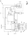
- FIG. 4 shows a fuel supply system 100 which is equipped with a volume flow-based, pump-synchronous, in particular cylinder-selective, rail pressure control according to FIGS Figure 2A and 2 B is operated.
- a high-pressure pump 1 is supplied with fuel from a fuel tank 3 by a pre-feed pump 2 via a low-pressure line 2.1.
- a filter unit 5 is located in the low-pressure line 2.1 and a dual sensor 6, which measures pressure p6 and temperature T6 upstream of the high-pressure pump 1 in the low-pressure line 2.1, is arranged.
- the high-pressure pump 1 pumps fuel via a high-pressure line 1.4 into a fuel reservoir, in particular into a fuel rail 4.
- the fuel rail 4 includes a rail pressure sensor 7, which detects the rail pressure p7 in the fuel rail 4.
- the fuel rail 4 also includes a pressure regulating valve 8 which, within the method, diverts a predeterminable volume flow V8 into the low-pressure line 2.1 from the fuel rail 4 via a return line 8.2.1.
- the injectors 9n have leakage lines which open into a common return line 9.3.
- the return line 9.3 opens into a high pressure pump return line 1.3 of the high pressure pump 1, which leads back to the fuel tank 3.
- a control unit S1 in particular an engine control unit, is directly connected to the duo sensor 6, the high pressure pump 1, the pressure control valve 8, the rail pressure sensor 7 and the injectors 91, 92, 93, 94 and in the exemplary embodiment indirectly via control lines (without reference symbols) a control unit S2 is connected to the prefeed pump 2 designed as a low-pressure pump.
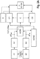
- the Figure 2A shows the volume flow-based pump-synchronous control structure for rail pressure control in the basic concept, which is stored in an electronic control device, in particular control device S1, which is set up to carry out one of the methods presented above.
- the control device S1 and the control device S2 are operated via a computer program for executing the method, a machine-readable storage medium with the computer program recorded thereon being provided on the computer.
- volume flow-based pump-synchronous control structure for rail pressure control is based on the Figure 2A explained in detail below.
- the rail pressure sensor 7 gives the control loop consisting of a pilot control model, a controller and an actuator of the high pressure pump 1 the corresponding pressure information.
- the input variable of the method for operating the fuel supply system 100 according to the invention is a specific volume flow which is supplied to the high pressure pump 1 or discharged through the pressure regulating valve 8.
- the object of the invention is thus that the complete high-pressure regulation, i.e. the rail pressure high-pressure regulation within the rail 4 of the fuel supply system 100, from a time-based cyclical calculation of a rail pressure regulator for regulating the rail pressure in the rail 4 to a volume flow-based and pump-synchronous based on the engine segment of the internal combustion engine discrete calculation for rail pressure control (in a two-digit concept pressure control valve control and high pressure pump control) is converted.
- the pressure information p7 actual from the rail pressure sensor 7 of an engine-synchronous / pump-synchronous segment is compared with the target rail pressure p7 target of the preceding engine-synchronous / pump-synchronous segment (one speaks of the delayed target rail pressure) in order to determine the discrete control deviation ⁇ p7.
- This pressure difference ⁇ p7 is converted into a volume difference via the modulus of elasticity E of the fuel and via the fuel temperature T6 determined by means of the duo sensor 6 and processed as an input variable ⁇ V Rail in a control system.
- This volume difference ⁇ V Rail is calculated with the aid of the digital metering unit (not shown), which is preferably arranged in the pump chamber of the high-pressure pump 1, or by controlling the Pressure regulating valve 8 is supplied as an input variable to the controlled system and the actuators of high pressure pump 1 or pressure regulating valve 8 are activated, whereby the discretization, i.e. the calculation of the volume difference ⁇ V Rail for each motor segment can be varied pump-synchronously.
- the volume balance of the volume flow-based segment-synchronous calculation is based on a volume-constant room volume V H of the high-pressure system in which there is a certain volume of fuel, depending on the pressure, which is basically supplied via the high-pressure pump 1 and discharged via the pressure control valve 1.
- the volumes a) and b) are taken on an event-related basis, while c) the permanent fuel leakage V DLeck of the high-pressure system is discretized via a Z transformation.
- there is an event-related discretization of the permanent leakage V DLeck of the high pressure system so that the volumes a), b), c) can be added accordingly as taken from the high pressure system as the total volume V Ges-Ab taken .
- the so-called load and / or speed-dependent change request for the rail pressure the so-called pressure change request (also referred to as the dynamic volume flow component) within the rail 4, which is generated by the supply of fuel volume (pressure increase) via the high-pressure pump 1 as a V ⁇ p rail specification or by discharging fuel volume (pressure reduction) via the pressure control valve 8 within the volume balance as a V ⁇ p-rail specification .
- the high-pressure pump 1 has, in a known manner and advantageously, a fixed assignment of the pump TDC segment synchronous / cylinder synchronous every 180 ° crank angle of the internal combustion engine to the cylinder piston TDCs of the cylinder pistons (not shown) of the internal combustion engine, the engine speed corresponding to the high pressure pump speed.
- a certain fixed offset can exist between the pump TDC and the cylinder piston TDC, but this is known and can be taken into account accordingly in the fixed assignment.
- the calculation according to the invention takes place via a trigger start signal nsync (cf. Figures 2A and 2 B and Figure 3 ), the calculation being segment-synchronous / cylinder-synchronous every 180 ° crank angle, with the calculation of the sizes of the controlled system for each of the cylinders or the associated injectors 9n which inject into this cylinder being carried out separately.
- nsync cf. Figures 2A and 2 B and Figure 3
- the volume flow-based pump-synchronous control structure for regulating the rail pressure of the high-pressure pump 1 comprises a signal acquisition module B1 for signal acquisition of the rail pressure p7 by means of the rail pressure sensor 7.
- the detection of the rail pressure p7 takes place synchronously within the module B1 for the signal detection of the rail pressure p7 in a measurement grid in ms steps, with an actual value being discrete segment-synchronously within the segment within the module B2, which is called the actual value discretization module p7 Isl as the minimum pressure p 7 is-min and a maximum pressure p 7 is-max detected and stored, wherein from these pressures p 7 is-min, p 7lst-max also as an actual value p7 lsl an average p7 actual 50% of the Press P 7Ist-min , p 7lst-max is calculated within the segment and also saved.
- the volume flow-based pump-synchronous control structure for the rail pressure control of the high-pressure pump 1 includes a setpoint specification module A1 for the setpoint specification of the rail pressure p7 Soll, which is stored in the form of map data in the computer program of the engine control unit, which stems from the respective combustion process applied and is specified.
- this target rail pressure p7 target is also discretized by any current default time grid, that is, a conversion takes place from the time “slice” to the segment "slice” at time nsync (trigger start signal), ie at the start of the calculation .
- target rail pressure p7 target is "frozen" at the beginning of a time slice of the segment at time nsync
- This procedure is necessary because the system always has a time delay.
- the control value of a pilot control generates an increase in volume flow into the rail after the pump has delivered. Therefore it becomes the Difference formation used setpoint p7 Soll delayed by exactly one work cycle and compared with the actual value p7 lsl of the following work cycle .
- the minimum pressure p 7min or the maximum jerk p 7max or the mean value p7 50% are available as the discrete actual value p7 lsl .
- the corresponding pressure-related calculation is carried out in the control error calculation module A2 / B2 (cf. Figure 2A ) in which the discretized setpoint rail pressure values p7 setpoint and the discretized actual rail pressure values p7 lsl enter and are compared segment-synchronously and output and stored calculated as a control error.
- a conversion into a volume flow-based control difference ⁇ V Rail i.e. a volume flow difference with the resolution of a differential equation, is carried out, where E is is pressure- and temperature-dependent specific modulus of elasticity of the respective fuel and V H , as explained above, the volume of space of the high-pressure fuel system of the fuel supply system 100.
- ⁇ V Rail V H E. p T ⁇ ⁇ p Rail
- This conversion into the segment-synchronous volume error ⁇ V Rail has the advantage that the non-linear fuel properties of the fuel are taken into account in the control.
- the non-linear properties of the fuel with regard to pressure and temperature and compressibility are not mapped in pressure-based systems
- the advantage of the present method is that these non-linearities are taken into account by converting them into the segment-synchronous volume error ⁇ V Rail .
- a discrete volume control difference ⁇ V Rail is available due to the features of the basic concept described, which is used directly for the volume flow-based actuators E1, E8 (high pressure pump 1 and pressure control valve 8).
- the controller module C, C1, C8 comprises, as a sub-module, a controller state machine C which, depending on the requirements, determines the pressure based on the volume flow / volume flow, i.e. depending on the discrete volume control difference ⁇ V determined in the conversion module A2 '/ B2' Rail increases or decreases, and it decides whether a control intervention via a PID controller module C1 of high-pressure pump 1 (cf. Figure 2A ) "pressure increasing" or via a PID controller module C8 of the pressure control valve 8 "pressure decreasing".
- the structure also includes according to Figure 2A a pre-control volume flow value module D as a fault controller for the segment-synchronous volume flow-based pre-control (reference variable with disturbance variable compensation) of the fuel supply system, the reference variable of which is merged with the PID controller module C1 of the high-pressure pump 1 and the PID controller module C8 of the pressure control valve 8, so that the PID controller modules C1, C8 only have to compensate for the control fluctuations of the fuel supply system.
- a pre-control volume flow value module D as a fault controller for the segment-synchronous volume flow-based pre-control (reference variable with disturbance variable compensation) of the fuel supply system, the reference variable of which is merged with the PID controller module C1 of the high-pressure pump 1 and the PID controller module C8 of the pressure control valve 8, so that the PID controller modules C1, C8 only have to compensate for the control fluctuations of the fuel supply system.
- the pre-control volume flow value module D is added as pilot control variables to the segment-synchronous volume flows mentioned under a) to d), so that the control system is already managed in the pre-control volume flow value module D.
- the values of the fault controller of the precontrol volume flow value module D which are regulated by the PID controller modules C1, C8 (see Fig Figure 2 ) to an output module E, which electrically controls the actuators E1 and E8 of the high pressure pump 1 and the pressure control valve 8 and adjusts the actuators E1 and E8 as required via the controlled system based on the pump segment and based on volume.
- n number of cylinders or the associated injectors 9n (cf. Figure 1 )
- a separate cylinder-selective control deviation ⁇ V Rail in particular a proportional component and / or an integrator component and / or a differential component, is calculated and, according to the cylinder-selective control deviation ⁇ V Rail , the control values E1, E8 cylinder for cylinder or injector for injector 9n or Injection valve for injection valve selected segment-synchronously and, as explained above, output based on volume flow for high-pressure pump 1 or pressure control valve 8.
- the injectors 9n receive the same quantity setpoints from cylinder to cylinder in stationary operation, but different quantity decreases V 9n result from the rail 4 due to injector scatter, according to the invention, for example, the individual integrator components of the cylinder-selective controllers C1 n , C8 n show the quantity deviations between the injectors 9 n , which can have various causes. Depending on the type of quantity discrepancy, the causes can be assigned to specific error groups with a high degree of probability.
- a discrete volume control difference ⁇ V Rail is available as an input variable for a controller module C, C1, C8 in the basic concept according to the invention, which is used directly for the volume flow-based actuators E1, E8 (high pressure pump 1 and pressure control valve 8), with segment-synchronous for every cylinder or injector 9n "only one" control structure is used repeatedly.
- the so-called “cylinder-selective control” in which several control structures are cylinder-selective (cf. Figure 2B ) are used, is explained in more detail below.
- a segment-synchronous discrete volume control difference ⁇ V Rail is available as an input variable for several (n) controller modules C1n, C8n, which according to the extension "cylinder-selective" directly for the volume flow-based actuators E1, E8 (high pressure pump 1 and pressure control valve 8 ) is used.
- the structure also includes according to Figure 2B a pre-control volume flow value module D as a fault controller for the segment-synchronous volume flow-based pre-control (reference variable with disturbance variable compensation) of the fuel supply system 100, the reference variable of which is combined with the PID controller module C1n of the high-pressure pump 1 and the PID controller module C8n of the pressure control valve 8, so that the PID controller modules C1n, C8n only have to compensate for the control fluctuations of the fuel supply system.
- a pre-control volume flow value module D as a fault controller for the segment-synchronous volume flow-based pre-control (reference variable with disturbance variable compensation) of the fuel supply system 100, the reference variable of which is combined with the PID controller module C1n of the high-pressure pump 1 and the PID controller module C8n of the pressure control valve 8, so that the PID controller modules C1n, C8n only have to compensate for the control fluctuations of the fuel supply system.
- the high-pressure control can now - as an extension of the basic concept - be performed on a cylinder-specific basis by means of the cylinder-selective control, i.e. for each cylinder or each injection process an adapted, cylinder-specific corrected manipulated variable is output as actuator output E1 of high-pressure pump 1 or actuator output E8 of pressure regulating valve 8.
- the respective PID controller modules C1n, C8n can each be evaluated separately and calibrated.
- the evaluation of the four individual PID controller modules C1n or C8n in the exemplary embodiment i.e. the comparison of the integrator components and proportional components that are different in steady-state operation, for example, allows a cylinder-related or injector-related error analysis and cause grouping, on the one hand Simple diagnostic function (on-board diagnosis without expansion) or a diagnostic function (on-board diagnosis without expansion) with a correction function is provided.
- a specific cylinder-related or injector-related error can be permitted up to a predefinable threshold value via the diagnostic function, and a cylinder-related or injector-related error correction only takes place after the threshold value has been exceeded.
- the injection quantity errors advantageously calling for replacement of the defective injector 9n within the on-board diagnosis or within the cylinder-selective Regulation can be taken into account and corrected.
- the cylinder-selective control information that is to say the individual injection quantity errors of the individual injectors 9n, can generally be adapted and used to improve the pilot control D of the injectors 9n.
- the respective cylinder-selective controlled variable C1n, C8n can also advantageously be converted into another reference variable, with particular consideration being given to the internal engine torque of the respective cylinder, so that a cylinder-selective torque-dependent control is made possible through the support of the cylinder-selective rail pressure control, in which the cylinder-selective control information in particular can be used for torque-cylinder equalization by, for example, transferring a corresponding pilot control value from the cylinder-selective rail pressure regulation to a cylinder-selective torque controller.
- the high-pressure control in the described non-cylinder-selective control or in the described cylinder-selective control outputs an adapted corrected manipulated variable in an actuator output E1 of the high-pressure pump 1 or in an actuator output E8 of the pressure control valve 8.
- PWM pulse width modulation
- AD converter analog-to-digital converter
- PWM-synchronous current recording systems in which a hardware filter with a high cut-off frequency is used to eliminate high-frequency interference, have the following disadvantages: A mean value-free acquisition cannot be performed. Sampling takes place in the frequency range of the HW filter with a high CPU load because the sampling frequency is coupled to the PWM base frequency. With small PWM duty cycles, aliasing errors can lead to undersampling, which leads to a shift in the mean value. The procedure is therefore rarely used.
- Time-synchronous current acquisition systems in which a HW filter with a low cut-off frequency is used to smooth the PWM oscillation on the current signal have the following Disadvantages: Due to the low cutoff frequency and high filter time constant, these HW filters have a high phase shift. The controller must be adapted to a relatively slow HW filter. The time-synchronous current detection systems also show poor control behavior in the event of malfunctions, because the actual value reaches the controller with a delay due to the slow HW filtering.
- the voltage drop across the measuring resistor is used with the help of a measuring resistor to determine the current in the actuator.
- This value is recorded cyclically by means of an AD converter and made available to the current control as an actual value.
- This current measured value is regulated in a closed control loop.
- this measured value must be filtered in front of the analog / digital converter using an analog hardware (HW) low-pass filter with a corresponding limit frequency (usually between 10 Hz and 50 Hz with time-synchronous current measurement).
- HW analog hardware
- This filter is usually an RC element.
- the actuators for the actuator output E1, E8 of the high pressure pump 1 and of the pressure control valve 8 of the high pressure control are the inner control loops, whereby the actual hydraulic pressure control already explained (compare the components of the hydraulic pressure control in the Figures 2A and 2 B and the associated description) represent the outer control loops.
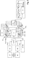
- the solution according to the invention consists in a modified signal processing or signal processing chain, which according to the invention includes an in Figure 3 includes observer model shown.
- an observer module W is arranged integrated in the signal processing chain and is advantageously used in the signal processing chain to control components 1 and 8.
- This observer W integrated in the signal processing chain improves the current detection of the high pressure pump 1 and the pressure control valve 8 and their current control in the described non-cylinder-selective rail pressure control and in the cylinder-selective rail pressure control.
- the current detection is improved by means of the observer model in such a way that the delay times and phase shifts of the current detection, which are caused by the analog filtering (HW filter) of the signal, are circumvented, with the model ensuring that the observer W is constantly tracked by converging a so-called observation error to zero, the observation error being defined as the difference between the measured value and the observed value.
- HW filter analog filtering
- the current detection system according to the invention is shown in Figure 3 arranged in the output module component E and in Figure 3 in a schematically illustrated system diagram extracted from the output module component E.
- the system according to the invention for current detection is based on time-synchronous current detection and a so-called state reconstruction or state vector construction.
- the system diagram extracted from output module component E illustrates a voltage value u (which corresponds to a pulsating coil current or a pulsating coil voltage of a conventional PWM-synchronous current measurement), which represents the input variable of the system for current measurement.
- the voltage u represents the input variable that of the coil 1 Ls + R. the control unit of the components 1, 8 to be controlled is supplied.
- the output of the coil 1 Ls + R. is a current value i 1, known as the effective value of the coil 1 Ls + R. is sought as a control current for controlling the components 1, 8, which cannot be measured by measurement without appropriate processing of the signal.
- the current value i 1 or the effective value of the coil 1 Ls + R. represents the input variable for a hardware filter HW for filtering the current value i 1 , which in turn outputs the current value i 2 , which finally represents the input variable for a software filter SW for damping the signal of the current value i 2 in the control unit, so that after this Signal processing chain a signal of a current value i 3 is available.
- the voltage value u thus represents the input value into the observer module W, the current value i 3 representing the output value of the signal processing chain, which is also made available to the observer module W, the observer module W via the underlying observer Model calculates a new voltage value u in parallel to the signal processing chain explained above.
- the observer W is continuously tracked in that the so-called observation error converges to zero, the observation error being defined as the difference between the measured value i1 and the observed value i3.
- This solution according to the invention enables a high performance and stability of the current detection corresponding to the requirements, whereby the inner current control loops with high performance are to be understood in detail as the following advantageous properties of the current detection according to the invention by means of observer W:
- This type of current detection has only a slight phase shift there on the
- the model value of the observer is regulated, which corresponds to the real current value which, however, due to the disadvantages of the phase response of the filtering, would only be recorded after the filter run time.
- the acquisition with observer is faster, so that ultimately the control based on it is also faster.
- the current detection according to the invention does not require averaging, that is to say it is more accurate in particular in contrast to the PWM-synchronous current detection (with averaging) that is used on all sides.
- no aliasing effects occur, that is to say incorrect signal determination with undersampling, as is the case with other current detection methods, does not occur.
Abstract
Die Erfindung betrifft ein Verfahren zum Regeln eines durch eine Hochdruckpumpe (1) in einem Kraftstoffspeicher (4) bewirkten Raildrucks (p7<sub>Soll</sub>) für ein Kraftstoffversorgungssystem (100) einer Brennkraftmaschine, wobei eine kurbelwinkelbezogene oder nockenwinkelbezogene feste Winkeldifferenz der Brennkraftmaschine zwischen einer Oberen-Totpunkt-Position eines Zylinderkolbens eines Zylinders der Brennkraftmaschine und einer Oberen-Totpunkt-Position des Pumpenkolbens der Hochdruckpumpe (1) des Kraftstoffversorgungssystems (100) bei der Zumessung des Fördervolumens der Hochdruckpumpe (1) berücksichtigt wird.Es ist vorgesehen, dass wiederkehrend pumpensynchron je Segment, das einer Umdrehung einer Kurbelwelle und somit der Bewegung des Pumpenkolbens der Hochdruckpumpe (1) von der Oberen-Totpunkt-Position des Pumpenkolbens zur nächsten Oberen-Totpunkt-Position entspricht, eine Diskretisierung einer Regelabweichung (Δp<sub>7</sub>) des Raildrucks (p7) im Kraftstoffspeicher (4) vorgenommen und von der diskreten Regelabweichung (Δp<sub>7</sub>) ausgehend eine volumenbezogene diskrete Volumen-Regeldifferenz (ΔV<sub>Rail</sub>), insbesondere eine volumenbezogene diskrete zylinderselektive Volumen-Regeldifferenz (ΔV<sub>Rail</sub>) berechnet wird.The invention relates to a method for regulating a rail pressure (p7 <sub> Soll </sub>) caused by a high-pressure pump (1) in a fuel accumulator (4) for a fuel supply system (100) of an internal combustion engine, with a crank angle-related or cam angle-related fixed angle difference of Internal combustion engine between a top dead center position of a cylinder piston of a cylinder of the internal combustion engine and a top dead center position of the pump piston of the high pressure pump (1) of the fuel supply system (100) is taken into account when metering the delivery volume of the high pressure pump (1). that recurring pump-synchronously per segment, which corresponds to one revolution of a crankshaft and thus to the movement of the pump piston of the high-pressure pump (1) from the top dead center position of the pump piston to the next top dead center position, a discretization of a control deviation (Δp <sub> 7 </sub>) of the rail pressure (p7) in the fuel accumulator (4) vo r taken and based on the discrete control deviation (Δp <sub> 7 </sub>) a volume-related discrete volume control difference (ΔV <sub> Rail </sub>), in particular a volume-related discrete cylinder-selective volume control difference (ΔV <sub> Rail </sub>) is calculated.
Description
Die Erfindung betrifft ein Verfahren zum Regeln eines durch eine Hochdruckpumpe in einem Kraftstoffspeicher bewirkten Raildrucks für ein Kraftstoffversorgungssystem einer Brennkraftmaschine, wobei eine kurbelwinkelbezogene oder nockenwinkelbezogene feste Winkeldifferenz der Brennkraftmaschine zwischen einer Oberen-Totpunkt-Position eines Zylinderkolbens eines Zylinders der Brennkraftmaschine und einer Oberen-Totpunkt-Position des Pumpenkolbens der Hochdruckpumpe des Kraftstoffversorgungssystems bei der Zumessung des Fördervolumens der Hochdruckpumpe berücksichtigt wird.The invention relates to a method for regulating a rail pressure caused by a high pressure pump in a fuel accumulator for a fuel supply system of an internal combustion engine, wherein a crank angle-related or cam angle-related fixed angular difference of the internal combustion engine between an upper dead center position of a cylinder piston of a cylinder of the internal combustion engine and an upper dead center Position of the pump piston of the high-pressure pump of the fuel supply system is taken into account when metering the delivery volume of the high-pressure pump.
Aus der Druckschrift
Das bekannte Kraftstoffversorgungssystem umfasst einen Raildruckregler zur Anwendung des vorgeschlagenen Verfahrens. Eine Hochdruckpumpe wird von einer Vorförderpumpe über eine Niederdruckleitung mit Kraftstoff aus einem Tank versorgt. Über eine Hochdruckleitung pumpt die Hochdruckpumpe Kraftstoff in ein Kraftstoffrail. Das Fördervolumen der Hochdruckpumpe ist gemäß einem Fördervolumen-Steuerwert eingestellt, den ein Raildruckregler zur Regelung des Raildrucks im Kraftstoffrail berechnet hat. Der Raildruckregler ist aus einem PID-Regler und einer Vorsteuerungseinheit zusammengesetzt. Dem PID-Regler wird eine Raildruck-Regelabweichung zugeführt, die als Differenz des synchron zur Motordrehzahl berechneten Raildruck-Sollwertes und des synchron zur Motordrehzahl mit einem Raildrucksensor erfassten Raildruck-Istwertes berechnet worden ist, und berechnet synchron zur Motordrehzahl einen additiven Korrekturvolumenstrom. Eine synchron zur Motordrehzahl vorgenommene Berechnung bedeutet, dass diese Berechnung einmal pro durchlaufenen oberen Totpunkt des Brennkraftmotors erfolgt.The known fuel supply system comprises a rail pressure regulator for using the proposed method. A high-pressure pump is supplied with fuel from a tank by a pre-feed pump via a low-pressure line. The high-pressure pump pumps fuel into a fuel rail via a high-pressure line. The delivery volume of the high pressure pump is set according to a delivery volume control value that a rail pressure regulator has calculated to regulate the rail pressure in the fuel rail. The rail pressure controller is composed of a PID controller and a pilot control unit. A rail pressure control deviation is sent to the PID controller which has been calculated as the difference between the rail pressure setpoint value calculated synchronously with the engine speed and the actual rail pressure value recorded synchronously with the engine speed with a rail pressure sensor, and calculates an additive correction volume flow synchronously with the engine speed. A calculation carried out synchronously with the engine speed means that this calculation is carried out once for each top dead center of the internal combustion engine that has passed through.
Der Vorsteuerungseinheit wird eine synchron zur Motordrehzahl berechnete Einspritzmenge und eine erwünschter Druckänderungswert zugeführt, sodass die Vorsteuerungseinheit synchron zur Motordrehzahl einen Vorsteuerungswert berechnet. Die Summe des additiven Korrekturvolumenstroms und des Vorsteuerungswertes wird als Fördervolumen-Steuerwert an die Hochdruckpumpe gespeist, um das Fördervolumen des aktuellen Förderhubs vorzugeben und um den Raildruck-Sollwert ps im Kraftstoffrail einzustellen.An injection quantity calculated synchronously with the engine speed and a desired pressure change value are fed to the pilot control unit, so that the pilot control unit calculates a pilot control value synchronously with the engine speed. The sum of the additive correction volume flow and the precontrol value is fed to the high-pressure pump as a delivery volume control value in order to specify the delivery volume of the current delivery stroke and to set the rail pressure setpoint ps in the fuel rail.
Der Erfindung liegt die Aufgabe zugrunde die Raildruckregelung zu verbessern.The invention is based on the object of improving the rail pressure regulation.
Ausgangspunkt der Erfindung ist es, dass es bei einer klassischen zeitsynchronen Raildruckregelung, die im 10ms Abtastraster arbeitet, je nach Motordrehzahl zu Unter- oder Überabtastungen des motorsynchronen Pumpenevents kommt. Dadurch kommt es in nachteiliger Weise zu Druckschwingungen in Form von Schwebungen sowie Aliasing, die selbst in stationären Betriebspunkten nicht vollständig ausgeregelt werden können.The starting point of the invention is that with a classic time-synchronous rail pressure control that works in a 10 ms sampling grid, depending on the engine speed, the engine-synchronous pump event is under- or oversampling. This disadvantageously results in pressure fluctuations in the form of beats and aliasing, which cannot be fully regulated even at stationary operating points.
Die herkömmliche Raildruckregelung soll ferner aufgabengemäß an die neu verfügbaren Hochdruckpumpen, die für jedes Arbeitsspiel einen Volumenstrom stellen können, angepasst werden.The conventional rail pressure control is also to be adapted, according to the task, to the newly available high pressure pumps, which can provide a volume flow for each work cycle.
Dabei soll eine bestmögliche Regelperformance mit Abweichungen zwischen Soll- und Istwert von weniger als 2% des aktuellen Sollwerts erreicht werden. Weiterhin soll Rechenzeit und Codespeicher im Steuergerät eingespart werden, und der Kalibrierungs- und Absicherungsaufwand soll reduziert sowie eine einfache Anpassung an verschiedene Pumpenausführungen, Druckregelventilvarianten und Hochdruckkomponenten ermöglicht werden.The best possible control performance with deviations between setpoint and actual value of less than 2% of the current setpoint should be achieved. Furthermore, computing time and code memory in the control unit should be saved, the calibration and validation effort should be reduced and simple adaptation to different pump designs, pressure control valve variants and high-pressure components should be made possible.
Insbesondere negativ wirken sich diese Effekte bei modernen Hochdruckpumpen aus, bei denen das Fördervolumen von einem Förderhub zum nächsten im kompletten Stellbereich beeinflusst wird. Abhilfe schafft bisher nur eine extrem geringe Kreisverstärkung, womit der klassische zeitsynchrone Raildruckregler, insbesondere in dynamischen Druckänderungssituationen dem nachfolgend erläuterten Verfahren gemäß der Erfindung weit unterlegen ist.These effects have a particularly negative effect on modern high-pressure pumps, in which the delivery volume is influenced from one delivery stroke to the next in the entire setting range. So far, the only remedy has been an extremely low loop gain, which is the classic Time-synchronous rail pressure regulator, especially in dynamic pressure change situations, is far inferior to the method according to the invention explained below.
Gemäß den vorhergehenden Ausführungen ist bereits ein Verfahren zum Regeln eines durch eine Hochdruckpumpe in einem Kraftstoffspeicher bewirkten Raildrucks für ein Kraftstoffversorgungssystem einer Brennkraftmaschine bekannt, wobei eine kurbelwinkelbezogene oder nockenwinkelbezogene feste Winkeldifferenz der Brennkraftmaschine zwischen einer Oberen-Totpunkt-Position eines Zylinderkolbens eines Zylinders der Brennkraftmaschine und einer Oberen-Totpunkt-Position des Pumpenkolbens der Hochdruckpumpe des Kraftstoffversorgungssystems bei der Zumessung des Fördervolumens der Hochdruckpumpe berücksichtigt wird.According to the preceding statements, a method for regulating a rail pressure caused by a high-pressure pump in a fuel accumulator for a fuel supply system of an internal combustion engine is known, with a crank angle-related or cam angle-related fixed angle difference of the internal combustion engine between a top dead center position of a cylinder piston of a cylinder of the internal combustion engine and a Top dead center position of the pump piston of the high pressure pump of the fuel supply system is taken into account when metering the delivery volume of the high pressure pump.
Erfindungsgemäß ist jetzt vorgesehen, dass wiederkehrend pumpensynchron je Segment, das einer Umdrehung einer Kurbelwelle und somit der Bewegung des Pumpenkolbens der Hochdruckpumpe von der Oberen-Totpunkt-Position des Pumpenkolbens zur nächsten Oberen-Totpunkt-Position entspricht, eine Diskretisierung einer Regelabweichung des Raildrucks im Kraftstoffspeicher vorgenommen und von der diskreten Regelabweichung ausgehend eine volumenbezogene diskrete Volumen-Regeldifferenz, insbesondere zylinderselektiv berechnet wird.According to the invention it is now provided that recurring pump-synchronously per segment, which corresponds to one revolution of a crankshaft and thus the movement of the pump piston of the high-pressure pump from the top dead center position of the pump piston to the next top dead center position, a discretization of a control deviation of the rail pressure in the fuel accumulator and based on the discrete control deviation, a volume-related discrete volume control difference, in particular cylinder-selective, is calculated.
Erfindungsgemäß wird die diskrete Regelabweichung als Differenz aus dem diskretisierten Ist-Raildruck und dem diskretisierten Soll-Raildruck, insbesondere zylinderselektiv berechnet, indem eine diskretisierte Druckinformation eines Raildruck-Sensor des aktiv erfassten pumpensynchronen Segmentes mit dem diskretisierten Soll-Raildruck des um ein Arbeitsspiel vorhergehenden pumpensynchronen Segmentes verglichen wird, um die diskrete, insbesondere zylinderselektive Regeldifferenz zu bestimmen.According to the invention, the discrete control deviation is calculated as the difference between the discretized actual rail pressure and the discretized target rail pressure, in particular cylinder-selectively, by combining a discretized pressure information of a rail pressure sensor of the actively detected pump-synchronous segment with the discretized target rail pressure of the previous pump-synchronous segment by one work cycle is compared in order to determine the discrete, in particular cylinder-selective control difference.
Bevorzugt wird die volumenbezogene diskrete Volumen-Regeldifferenz als Eingangsgröße einem Regelbaustein für die Hochdruckpumpe und einem Regelbaustein für ein dem Kraftstoffspeicher zugeordnetes Druckregelventil zugeführt, wobei die diskrete Volumen-Regeldifferenz mit einem Vorsteuer-Baustein verknüpft wird, wodurch pumpensynchron und insbesondere zylinderselektiv je Segment die Stellgrößen für die Hochdruckpumpe und das Druckregelventil in einem Ausgabe-Baustein berechnet und den Stellgliedern der Hochdruckpumpe und des Druckregelventils zur volumenbasierten und insbesondere zylinderselektiven Einstellung des Raildrucks zugeführt werden.Preferably, the volume-related discrete volume control difference is fed as an input variable to a control module for the high-pressure pump and a control module for a pressure control valve assigned to the fuel accumulator, the discrete volume control difference being linked to a pilot control module, whereby the manipulated variables for each segment are pump-synchronized and in particular cylinder-selective the high pressure pump and the pressure regulating valve are calculated in an output module and fed to the actuators of the high pressure pump and the pressure regulating valve for volume-based and, in particular, cylinder-selective setting of the rail pressure.
Bevorzugt ist bei der nicht zylinderselektiven Vorgehensweise und der zylinderselektiven Vorgehensweise vorgesehen, dass die Stellgrößen der Stellglieder der Komponenten zum Regeln des Raildrucks in dem Kraftstoffspeicher einem Ausgabe-Baustein zugeführt und in dem Ausgabe-Baustein zur volumenbasierten Einstellung des Raildrucks berechnet werden, wobei eine Stromerfassung und Stromregelung der Stellglieder auf der Basis eines Beobachter-Modells durchgeführt wird.In the case of the non-cylinder-selective approach and the cylinder-selective approach, it is preferably provided that the manipulated variables of the actuators of the components for regulating the rail pressure in the fuel accumulator are fed to an output module and are calculated in the output module for the volume-based setting of the rail pressure, with current detection and Current control of the actuators is carried out on the basis of an observer model.
Bevorzugt ist bei der nicht zylinderselektiven Vorgehensweise vorgesehen, dass die volumenbezogene diskrete Volumen-Regeldifferenz als Eingangsgröße einem Regelbaustein für die Hochdruckpumpe und einem Regelbaustein für ein dem Kraftstoffspeicher zugeordnetes Druckregelventil zugeführt wird, wobei die diskrete Volumen-Regeldifferenz mit einem Vorsteuer-Baustein verknüpft wird, wodurch pumpensynchron je Segment die Stellgrößen für die Hochdruckpumpe und das Druckregelventil in einem Ausgabe-Baustein berechnet und den Stellgliedern der Hochdruckpumpe und des Druckregelventils zur volumenbasierten Einstellung des Raildrucks zugeführt werden.In the case of the non-cylinder-selective procedure, it is preferably provided that the volume-related discrete volume control difference is fed as an input variable to a control module for the high-pressure pump and a control module for a pressure control valve assigned to the fuel accumulator, the discrete volume control difference being linked to a pilot control module, whereby pump-synchronously per segment the manipulated variables for the high-pressure pump and the pressure control valve are calculated in an output module and fed to the actuators of the high-pressure pump and the pressure control valve for volume-based adjustment of the rail pressure.
Vorgesehen ist bei der nicht zylinderselektiven Vorgehensweise ferner, dass die diskrete Regelabweichung als Differenz aus dem diskretisierten Ist-Raildrucks und dem diskretisierten Soll-Raildruck berechnet wird, indem eine diskretisierte Druckinformation eines Raildruck-Sensor des aktiv erfassten pumpensynchronen Segmentes mit dem diskretisierten Soll-Raildruck des um ein Arbeitsspiel vorhergehenden pumpensynchronen Segmentes verglichen wird, um die diskrete Regeldifferenz zu bestimmen.In the case of the non-cylinder-selective approach, it is also provided that the discrete control deviation is calculated as the difference between the discretized actual rail pressure and the discretized target rail pressure by adding discretized pressure information from a rail pressure sensor of the actively detected pump-synchronous segment with the discretized target rail pressure of the is compared to a work cycle preceding the pump-synchronous segment in order to determine the discrete control difference.
Bei der anderen die Grundkonzeption erweiternden zylinderselektiven Vorgehensweise, wird die volumenbezogene diskrete Volumen-Regeldifferenz zylinderselektiv berechnet, indem die volumenbezogene diskrete Volumen-Regeldifferenz als zylinderselektive Eingangsgrößen einem Regelbaustein für die Hochdruckpumpe und einem Regelbaustein für ein dem Kraftstoffspeicher zugeordnetes Druckregelventil zugeführt wird, wobei die diskrete Volumen-Regeldifferenz mit einem Vorsteuer-Baustein verknüpft wird, wodurch pumpensynchron und zylinderselektiv je Segment die Stellgrößen für die Hochdruckpumpe und das Druckregelventil in einem Ausgabe-Baustein berechnet und den Stellgliedern der Hochdruckpumpe und des Druckregelventils zur volumenbasierten zylinderselektiven Einstellung des Raildrucks zugeführt werden.In the other, cylinder-selective approach, which extends the basic concept, the volume-related discrete volume control difference is calculated cylinder-selectively by feeding the volume-related discrete volume control difference as cylinder-selective input variables to a control module for the high-pressure pump and a control module for a pressure control valve assigned to the fuel reservoir, the discrete volume -Control difference is linked to a pilot control module, whereby the manipulated variables for the high pressure pump and the pressure control valve are calculated in an output module for each segment in a pump-synchronized and cylinder-selective manner and fed to the actuators of the high-pressure pump and the pressure control valve for volume-based, cylinder-selective adjustment of the rail pressure.
Bevorzugt ist bei der zylinderselektiven Vorgehensweise vorgesehen, dass die diskrete Regelabweichung als Differenz aus dem diskretisierten Ist-Raildrucks und dem diskretisierten Soll-Raildruck zylinderselektiv berechnet wird, indem eine diskretisierte Druckinformation eines Raildruck-Sensor des aktiv erfassten pumpensynchronen Segmentes mit dem diskretisierten Soll-Raildruck, des um ein Arbeitsspiel vorhergehenden pumpensynchronen Segmentes verglichen wird, um die diskrete zylinderselektive Regeldifferenz zu bestimmen, wie in der Beschreibung detailliert erläutert ist.In the case of the cylinder-selective procedure, it is preferably provided that the discrete control deviation is the difference between the discretized actual rail pressure and the discretized Target rail pressure is calculated cylinder-selectively by comparing discretized pressure information from a rail pressure sensor of the actively detected pump-synchronous segment with the discretized target rail pressure of the pump-synchronous segment preceding one work cycle in order to determine the discrete cylinder-selective control difference, as detailed in the description is explained.
Erfindungsgemäß wird der Soll-Raildruck zu einem Zeitpunkt diskretisiert wird, der mit einem Triggerstartsignal festgelegt wird, das wiederkehrend zu Beginn eines pumpensynchronen Segmentes ausgegeben wird. Vorgesehen ist, dass der Ist-Raildruck innerhalb des durch das Triggerstartsignal gestarteten Segmentes wiederkehrend erfasst und diskretisiert wird.According to the invention, the target rail pressure is discretized at a point in time that is established with a trigger start signal that is output repeatedly at the beginning of a pump-synchronous segment. Provision is made for the actual rail pressure within the segment started by the trigger start signal to be repeatedly recorded and discretized.
Dabei ist bevorzugt vorgesehen, dass der Ist-Raildruck, der innerhalb des pumpensynchronen Segmentes wiederkehrend erfasst wird, als
- in dem Segment maximaler Ist-Raildruck und
- in dem Segment minimaler Ist-Raildruck und
- in dem Segment berechneter Mittelwert
- in the segment maximum actual rail pressure and
- in the segment minimum actual rail pressure and
- mean calculated in the segment
Vorgesehen ist ferner bevorzugt, dass für die Regelung, insbesondere zylinderselektive Regelung als Ist-Wert der erfasste minimale diskrete Druck oder der erfasste maximale diskrete Druck oder der diskrete Mittelwert zum Vergleich mit dem diskreten Soll-Raildruck verwendet wird, wobei je nach Systemanforderung bei einem Druckaufbau der maximale diskrete Druck und bei einem Druckabbau der minimale diskrete Druck verwendet wird, um Regelschwingungen, insbesondere zylinderselektiv Regelschwingungen zu reduzieren beziehungsweise Über- oder Unterschwinger, insbesondere zylinderselektive Über- oder Unterschwinger zu vermeiden.It is also preferred that for the regulation, in particular cylinder-selective regulation, the recorded minimum discrete pressure or the recorded maximum discrete pressure or the discrete mean value for comparison with the discrete target rail pressure is used as the actual value, with a pressure build-up depending on the system requirements the maximum discrete pressure and, in the event of a pressure reduction, the minimum discrete pressure is used in order to reduce control oscillations, in particular cylinder-selective control oscillations or to avoid overshoots or undershoots, in particular cylinder-selective overshoots or undershoots.
Ein besonderer Aspekt der Erfindung sieht ferner vor, dass die diskrete Regelabweichung in die volumenstrombasierte diskrete Volumen-Regeldifferenz beziehungsweise volumenstrombasierte diskrete zylinderselektive Volumen-Regeldifferenz umgerechnet wird, wobei zusätzlich eine Kraftstoff-Dauerleckage des Hochdrucksystems des Kraftstoffversorgungssystems durch Addition berücksichtigt wird.A special aspect of the invention also provides that the discrete control deviation is converted into the volume flow-based discrete volume control difference or volume flow-based discrete cylinder-selective volume control difference, with a permanent fuel leakage of the high-pressure system of the fuel supply system being taken into account by addition.
Die druckbasierte diskretisierte Regelabweichung ΔPRail beziehungsweise druckbasierte diskretisierte zylinderselektive Regelabweichung ΔPRail wird in vorteilhafter Weise in eine volumenstrombasierte Volumen-Regeldifferenz ΔVRail beziehungsweise volumenstrombasierte zylinderselektive Volumen-Regeldifferenz ΔVRail umgerechnet, wobei bei der Umrechnung das druck - und temperaturabhängige spezifische Elastizitätsmodul E des jeweiligen Kraftstoffs und das Raumvolumen VH des Kraftstoff-Hochdrucksystems des Kraftstoffversorgungssystems gemäß der Umrechnungsformel ![]()
![]()
Bei der pumpensynchronen segmentweise wiederkehrenden Umrechnung der druckbasierten diskreten Regelabweichung, insbesondere zylinderselektiven Regelabweichung in die volumenbezogene diskrete Volumen-Regeldifferenz, insbesondere zylinderselektive Volumen-Regeldifferenz werden,
- a) die Kraftstoff-Einspritzmengen der Injektoren, insbesondere zylinderselektiv und
- b) die Kraftstoff-Schaltleckagen der Injektoren, insbesondere zylinderselektiv und
- c) ein Druckänderungswunsch bezüglich des Soll-Raildrucks des Kraftstoffspeichers, insbesondere zylinderselektiv berücksichtigt,
wobei ferner - d) die Kraftstoff-Dauerleckage des Hochdrucksystems des Kraftstoffversorgungssystems durch eine pumpensynchrone segmentweise wiederkehrende separate Umrechnung mit einer Z-Transformation ermittelt und der volumenbezogenen diskreten Volumen-Regeldifferenz hinzugefügt wird, beziehungsweise bei zylinderselektiver Vorgehensweise, wird die Kraftstoff-Dauerleckage den volumenbezogenen diskreten zylinderselektiven Volumen-Regeldifferenzen anteilig hinzugefügt.
- a) the fuel injection quantities of the injectors, in particular cylinder-selective and
- b) the fuel switching leaks of the injectors, in particular cylinder-selective and
- c) a pressure change request with regard to the target rail pressure of the fuel accumulator, in particular taken into account for each cylinder,
furthermore - d) the permanent fuel leakage of the high pressure system of the fuel supply system is determined by a pump-synchronous, segment-wise recurring separate conversion with a Z-transformation and added to the volume-related discrete volume control difference, or in the case of a cylinder-selective approach, the fuel-permanent leakage becomes the volume-related discrete cylinder-selective volume control differences added proportionally.
Erfindungsgemäß ist es vorgesehen, dass die Injektoren im stationären Betrieb von Zylinder zu Zylinder dieselben Mengen-Sollwerte erhalten, die zylinderselektiv mit den Mengenabnahmen aus dem Rail verglichen werden, wobei zylinderselektiv Einspritzmengenfehler festgestellt werden, die den Injektoren zugeordnet werden, wobei eine Art der Mengenabweichungen bestimmten Fehlergruppen zugeordnet wird. Die Einspritzmengenfehler werden in vorteilhafter Weise ursachenabhängig, insbesondere in Abhängigkeit der Höhe, des sich im Soll/Ist-Vergleich ergebenden Einspritzmengenfehler gruppiert, wobei die Injektoren im Betrieb einer Fehlergruppe mit einem Injektordefekt, einer Fehlergruppe mit einer alterungsbedingten Injektordrift oder einer Fehlergruppe mit einer sich ändernden Schaltleckagemenge zugeordnet werden, wobei die Einspritzmengenfehler innerhalb der zylinderselektiven Regelung im Regler ermittelt und in vorteilhafter Weise im Einspritzsystem korrigiert werden und/oder zu einem Austausch des/der jeweiligen Injektors/Injektoren führen.According to the invention, it is provided that the injectors receive the same quantity target values from cylinder to cylinder in stationary operation, which are compared cylinder-selectively with the quantity decreases from the rail, with injection quantity errors being determined for each cylinder, which are assigned to the injectors, one type of quantity deviations being determined Is assigned to error groups. The injection quantity errors are grouped in an advantageous manner depending on the cause, in particular depending on the level of the injection quantity error resulting from the target / actual comparison, the injectors during operation of an error group with an injector defect, an error group with an age-related injector drift or an Error group can be assigned with a changing switching leakage quantity, the injection quantity errors being determined within the cylinder-selective control in the controller and advantageously corrected in the injection system and / or leading to an exchange of the respective injector (s).
Eine Korrektur im Einspritzsystem kann auf verschiedene Art und Weise erfolgen. In einer bevorzugten Ausgestaltung findet die Korrektur durch Änderung der Injektor-Ansteuerdauer statt.A correction in the injection system can be made in various ways. In a preferred embodiment, the correction takes place by changing the injector control duration.
Das nicht zylinderselektive Kraftstoffversorgungssystem (Grundkonzeption) und das zylinderselektive Kraftstoffversorgungssystem(Erweiterung der Grundkonzeption) unterscheiden sich hinsichtlich der Bausteine, wie nachfolgend deutlich wird.The non-cylinder-selective fuel supply system (basic concept) and the cylinder-selective fuel supply system (extension of the basic concept) differ in terms of the components, as will become clear below.
Das dem Verfahren zugehörige Kraftstoffversorgungssystem ist zur Durchführung des Verfahrens eingerichtet, wobei das Kraftstoffversorgungssystem in der Grundkonzeption (ohne zylinderselektive Raildruckregelung) zur Ermittlung einer diskreten Eingangsgröße für einen Regler-Baustein für die Hochdruckpumpe und zur Ermittlung einer diskreten Eingangsgröße für einen Regler-Baustein für ein dem Kraftstoffspeicher zugeordnetes Druckregelventil folgende weitere Bausteine umfasst,
- einen Sollwertvorgabe-Baustein des Raildrucks und eine zugehörigen Sollwert-Diskretisierungs-Baustein und
- einen Istwert-Signalerfassungs-Baustein des Raildrucks und einen Istwert-Diskretisierungs-Baustein,
- sowie einen Regelfehler-Berechnungs-Baustein und
- einen Umrechnungs-Baustein umfasst, der aus einer druckbasierten diskretisieren Regeldifferenz eine Umrechnung in eine volumenstrombasierte Regeldifferenz vornimmt,
- wobei der Umrechnungs-Baustein mit einer Regler-Zustandsmaschine verknüpft ist, welche die diskrete Eingangsgröße für den Regler-Baustein der Hochdruckpumpe und die diskreten Eingangsgröße für den Regler-Baustein des Druckregelventils ausgibt,
- wobei die Regler-Bausteine mit einem Vorsteuer-Baustein verknüpft sind, wodurch mittels des Vorsteuer-Bausteins und der aufgeschalteten Regler-Bausteine pumpensynchron je Segment die Stellgrößen für die Hochdruckpumpe und das Druckregelventil einem Ausgabe-Baustein zugeführt und berechnet werden, und den Stellgliedern der Hochdruckpumpe und des Druckregelventils zur volumenbasierten Einstellung des Raildrucks zugeführt werden.
- a setpoint specification module for the rail pressure and an associated setpoint discretization module and
- an actual value signal acquisition module for the rail pressure and an actual value discretization module,
- as well as a control error calculation module and
- includes a conversion module that converts a pressure-based discretized control difference into a volume flow-based control difference,
- the conversion module being linked to a controller state machine which outputs the discrete input variable for the controller module of the high-pressure pump and the discrete input variable for the controller module of the pressure control valve,
- The controller modules are linked to a pilot control module, whereby by means of the pilot control module and the connected controller modules, the manipulated variables for the high-pressure pump and the pressure control valve are fed to an output module and calculated for each segment, and the actuators of the high-pressure pump and the pressure control valve for volume-based adjustment of the rail pressure.
Das dem Verfahren zugehörige Kraftstoffversorgungssystem ist in der Erweiterung der Grundkonzeption, nämlich mit zylinderselektiver Raildruckregelung zur Durchführung des Verfahrens erweitert eingerichtet, wobei das Kraftstoffversorgungssystem zu der Ermittlung der jeweiligen diskreten Eingangsgröße des jeweiligen Zylinders zylinderselektiv mehrere Regler-Bausteine für die Hochdruckpumpe und zur Ermittlung einer diskreten Eingangsgröße des jeweiligen Zylinders zylinderselektiv mehrere Regler-Bausteine für ein dem Kraftstoffspeicher zugeordnetes Druckregelventil folgende weitere Bausteine umfasst,
- einen Sollwertvorgabe-Baustein des Raildrucks und eine zugehörigen Sollwert-Diskretisierungs-Baustein und
- einen Istwert-Signalerfassungs-Baustein des Raildruck und einen Istwert-Diskretisierungs-Baustein,
- sowie einen Regelfehler-Berechnungs-Baustein und
- einen Umrechnungs-Baustein umfasst, der aus einer druckbasierten diskretisieren zylinderselektiven Regeldifferenz eine Umrechnung in eine volumenstrombasierte zylinderselektive Regeldifferenz vornimmt,
- wobei der Umrechnungs-Baustein mit einer Regler-Zustandsmaschine verknüpft ist, welche zylinderselektiv die diskrete Eingangsgröße dem jeweiligen Regler-Baustein der Hochdruckpumpe und zylinderselektiv die diskreten Eingangsgröße dem jeweiligen Regler-Baustein des Druckregelventils ausgibt,
- wobei die Regler-Bausteine jeweils zylinderselektiv mit einem Vorsteuer-Baustein verknüpft sind, wodurch mittels des Vorsteuer-Bausteins und der aufgeschalteten zylinderselektiven Regler-Bausteine pumpensynchron je Segment die Stellgrößen für die Hochdruckpumpe und das Druckregelventil einem Ausgabe-Baustein zugeführt und berechnet werden, und den Stellgliedern der Hochdruckpumpe und des Druckregelventils zur volumenbasierten zylinderselektiven Einstellung des Raildrucks zugeführt werden.
- a setpoint specification module for the rail pressure and an associated setpoint discretization module and
- an actual value signal acquisition module for the rail pressure and an actual value discretization module,
- as well as a control error calculation module and
- a conversion module that converts a pressure-based, discretized, cylinder-selective control difference into a volume flow-based, cylinder-selective control difference,
- The conversion module is linked to a controller state machine, which outputs the discrete input variable to the respective controller module of the high-pressure pump on a cylinder-specific basis and the discrete input variable to the respective controller module of the pressure control valve on a cylinder-specific basis,
- wherein the controller modules are each cylinder-selectively linked with a pilot control module, whereby by means of the pilot control module and the connected cylinder-selective controller modules pump-synchronously per segment, the manipulated variables for the high pressure pump and the pressure control valve are fed to an output module and calculated, and the Actuators of the high-pressure pump and the pressure control valve for volume-based cylinder-selective adjustment of the rail pressure are supplied.
Ein noch weiterer Aspekt der Erfindung besteht darin, dass das Kraftstoffversorgungssystem einen Beobachter-Baustein umfasst, der eine Signalverarbeitungskette zur Stromerfassung und Stromregelung der Stellglieder des Kraftstoffversorgungssystem beobachtet, wie in der Beschreibung ebenfalls detailliert ist.Yet another aspect of the invention is that the fuel supply system comprises an observer module which observes a signal processing chain for current detection and current regulation of the actuators of the fuel supply system, as is also detailed in the description.
In vorteilhafter Weise wird die Brennkraftmaschine mit einem beliebigen flüssigen Kraftstoff oder Kraftstoffgemisch betrieben, wodurch sich in vorteilhafter Weise die Linearisierung der Umrechnung von Druckdifferenz in Volumenstromdifferenz durch ein physikalisch anderes Elastizitätsmodul an den jeweiligen Kraftstoff anpassen lässt. Dadurch ist das erläuterte Verfahren und die Ausgestaltung des Kraftstoffversorgungssystems nicht nur für Dieselmotoren, die insbesondere als Common-Rail Dieselmotoren ausgeführt sind, sondern auch für Ottomotoren, die ein ottomotorisches - fremdgezündetes - Brennverfahren verwenden, anwendbar und einsetzbar.The internal combustion engine is advantageously operated with any liquid fuel or fuel mixture, as a result of which the linearization of the conversion of pressure difference into volume flow difference can be adapted to the respective fuel by a physically different modulus of elasticity. As a result, the explained method and the design of the fuel supply system are not only suitable for diesel engines, which are designed in particular as common rail diesel engines, but also applicable and usable for gasoline engines that use a gasoline engine - externally ignited - combustion process.
Die Erfindung wird nachfolgend anhand der zugehörigen Zeichnungen erläutert. Es zeigen:
Figur 1- eine schematische Darstellung eines Kraftstoffversorgungssystems, das mit einer volumenstrombasierten pumpensynchronen Regelstruktur, insbesondere volumenstrombasierten pumpensynchronen und zylinderselektiven Regelstruktur zur Raildruckregelung gemäß dem erfindungsgemäßen Verfahren betrieben wird;
- Figur 2A
- die volumenstrombasierte pumpensynchrone Regelstruktur zur Raildruckregelung, die in einem elektronischen Steuergerät mit einem Mikroprozessor abgelegt und zur Ausführung des erfindungsgemäßen Verfahrens eingerichtet ist;
- Figur 2B
- die volumenstrombasierte pumpensynchrone und zylinderselektive Regelstruktur zur Raildruckregelung, die in einem elektronischen Steuergerät mit einem Mikroprozessor abgelegt und zur Ausführung des erfindungsgemäßen Verfahrens eingerichtet ist;
- Figur 3
- die erfindungsgemäße volumenstrombasierte pumpensynchrone Regelstruktur zur Raildruckregelung gemäß
Figur 2A oder die erfindungsgemäße volumenstrombasierte pumpensynchrone und zylinderselektive Regelstruktur zur Raildruckregelung gemäßFigur 2B mit Stromerfassung und Stromregelung der Stellglieder der Raildruckregelung weiter erfindungsgemäß auf der Basis eines Beobachter-Modells.
- Figure 1
- a schematic representation of a fuel supply system which is operated with a volume flow-based pump-synchronous control structure, in particular volume-flow-based pump-synchronous and cylinder-selective control structure for rail pressure control according to the method according to the invention;
- Figure 2A
- the volume flow-based pump-synchronous control structure for rail pressure control, which is stored in an electronic control unit with a microprocessor and is set up to carry out the method according to the invention;
- Figure 2B
- the volume flow-based pump-synchronous and cylinder-selective control structure for rail pressure control, which is stored in an electronic control unit with a microprocessor and is set up to carry out the method according to the invention;
- Figure 3
- the inventive volume flow-based pump-synchronous control structure for rail pressure control according to FIG
Figure 2A or the volume flow-based pump-synchronous and cylinder-selective control structure according to the invention for rail pressure control according to FIGFigure 2B with current detection and current regulation of the actuators of the rail pressure regulation further according to the invention on the basis of an observer model.
Die
Eine Hochdruckpumpe 1 wird von einer Vorförderpumpe 2 über eine Niederdruckleitung 2.1 mit Kraftstoff aus einem Kraftstofftank 3 versorgt. In der Niederdruckleitung 2.1 ist eine Filtereinheit 5 und ein Duo-Sensor 6, der Druck p6 und Temperatur T6 vor der Hochdruckpumpe 1 in der Niederdruckleitung 2.1 misst, angeordnet.A high-
Über eine Hochdruckleitung 1.4 pumpt die Hochdruckpumpe 1 Kraftstoff in einen Kraftstoffspeicher, insbesondere in ein Kraftstoff-Rail 4. Das Kraftstoff-Rail 4 umfasst einen Raildruck-Sensor 7, der den Raildruck p7 im Kraftstoff-Rail 4 erfasst.The high-
Das Kraftstoff-Rail 4 umfasst ferner ein Druckregelventil 8, welches innerhalb des Verfahrens einen vorgebbaren Volumenstrom V8 über eine Rücklaufleitung 8.2.1 in die Niederdruckleitung 2.1 aus dem Kraftstoff-Rail 4 absteuert.The
Zwischen dem Kraftstoff-Rail 4 und den Injektoren 9n; (n = 1, 2, 3...) 91, 92, 93, 94 sind die Injektorleitungen 4.9 dargestellt, über welche die Injektoren 9n mit Kraftstoff versorgt werden.Between the
Die Injektoren 9n weisen Leckageleitungen auf, die in eine gemeinsame Rücklaufleitung 9.3 münden. Die Rücklaufleitung 9.3 mündet in eine Hochdruckpumpen-Rücklaufleitung 1.3 der Hochdruckpumpe 1, die zum Kraftstofftank 3 zurückführt.The
Ein Steuergerät S1, insbesondere ein Motorsteuergerät ist über Steuerleitungen (ohne Bezugszeichen) direkt mit dem Duo-Sensor 6, der Hochdruckpumpe 1, dem Druckregelventil 8, dem Raildruck-Sensor 7 und den Injektoren 91, 92, 93, 94 und im Ausführungsbeispiel indirekt über ein Steuergerät S2 mit der als Niederdruckpumpe ausgelegten Vorförderpumpe 2 verbunden.A control unit S1, in particular an engine control unit, is directly connected to the
Die
Die volumenstrombasierte pumpensynchrone Regelstruktur zur Raildruckregelung wird anhand der
Die Grundidee des nachfolgend erläuterten Verfahrens für die zukünftigen Dieselmotoren, die als Common-Rail Dieselmotoren ausgeführt sind, besteht darin, dass ein benötigter Raildruck bis zu 2700 bar mit der Hochdruckpumpe 1 durch einen vorgebbaren Volumenstrom im Rail 4 erzeugt wird.The basic idea of the method explained below for the future diesel engines, which are designed as common rail diesel engines, is that a required rail pressure of up to 2700 bar is generated with the
Bei positiver Mengenbilanz, das heißt ansteigendem Volumenstrom im Rail 4 steigt der Druck im Rail 4 an. Der Raildruck-Sensor 7 gibt dem Regelkreis bestehend aus einem Vorsteuerungs-Modell, einem Regler und einem Stellglied der Hochdruckpumpe 1 die entsprechende Druckinformation.In the case of a positive quantity balance, that is to say an increasing volume flow in
Die Eingangsgröße des Verfahrens zum Betrieb des erfindungsgemäßen Kraftstoffversorgungssystems 100 ist erfindungsgemäß ein bestimmter Volumenstrom, welcher der Hochdruckpumpe 1 zugeführt oder durch das Druckregelventil 8 abgeführt wird.According to the invention, the input variable of the method for operating the
Der Gegenstand der Erfindung besteht somit darin, dass die komplette Hochdruckregelung mithin die Raildruck-Hochdruckregelung innerhalb des Rails 4 des Kraftstoffversorgungssystems 100, von einer zeitbasierten zyklischen Berechnung eines Raildruckreglers zur Regelung des Raildrucks im Rail 4 auf eine an das Motorsegment der Brennkraftmaschine angelehnte volumenstrombasierte und pumpensynchrone diskrete Berechnung zur Raildruckregelung (in einem Zweisteller-Konzept Druckregelventil-Ansteuerung und Hochdruckpumpen-Ansteuerung) umgestellt wird.The object of the invention is thus that the complete high-pressure regulation, i.e. the rail pressure high-pressure regulation within the
Dazu ist es erfindungsgemäß notwendig, die zu beachtenden Volumenströme und das zugehörige Modell der erfindungsgemäßen Regelstruktur diskret zu beschreiben.To this end, it is necessary according to the invention to discretely describe the volume flows to be observed and the associated model of the control structure according to the invention.
Dazu wird die Druckinformation p7Ist vom Raildruck-Sensor 7 eines motorsynchronen/pumpensynchronen Segmentes mit dem Soll-Raildruck p7Soll des vorhergehenden motorsynchronen/pumpensynchronen Segmentes (man spricht von dem verzögerten Soll-Raildruck) verglichen, um die diskrete Regelabweichung Δp7 zu bestimmen.For this purpose, the pressure information p7 actual from the
Diese Druckdifferenz Δp7 wird über das Elastizitätsmodul E des Kraftstoffs und über die mittels des Duo-Sensors 6 ermittelte Kraftstofftemperatur T6 in eine Volumendifferenz umgerechnet und als Eingangsgröße ΔVRail in einer Regelstrecke verarbeitet.This pressure difference Δp7 is converted into a volume difference via the modulus of elasticity E of the fuel and via the fuel temperature T6 determined by means of the
Diese Volumendifferenz ΔVRail wird mithilfe der digitalen Zumesseinheit (nicht dargestellt), die bevorzugt im Pumpenraum der Hochdruckpumpe 1 angeordnet ist oder durch Ansteuerung des Druckregelventils 8 als Eingangsgröße der Regelstrecke zugeführt und die Steller der Hochdruckpumpe 1 oder des Druckregelventils 8 werden angesteuert, wobei die Diskretisierung, das heißt die Berechnung Volumendifferenz ΔVRail für jedes Motorsegment pumpensynchron variiert werden kann.This volume difference ΔV Rail is calculated with the aid of the digital metering unit (not shown), which is preferably arranged in the pump chamber of the high-
Dazu wird eine Volumenbilanz erstellt, die physikalisch den sich einstellenden Druck p7Ist im Rail 4 beschreibt.For this purpose, a volume balance is created that physically describes the pressure p7 actual that is set in
Bei der Volumenbilanz der volumenstrombasierten segmentsynchronen Berechnung, wird von einem volumenkonstanten Raumvolumen VH des Hochdrucksystems ausgegangen, in dem sich druckabhängig eine bestimmtes Volumen an Kraftstoff befindet, der grundsätzlich über die Hochdruckpumpe 1 zugeführt und über das Druckregelventil 1 abgeführt wird.The volume balance of the volume flow-based segment-synchronous calculation is based on a volume-constant room volume V H of the high-pressure system in which there is a certain volume of fuel, depending on the pressure, which is basically supplied via the high-
Das Raumvolumen VH des Hochdrucksystem des Kraftstoffversorgungssystems 100 umfasst das Raumvolumen des Rails 4, das Raumvolumen der Injektorleitungen 4.9 zu den Injektoren 9n, das Raumvolumen in den Injektoren 9n bis zur Drosselstelle innerhalb der Injektoren 9n, die Zuleitung 1.4 der Hochdruckpumpe 1 zum Rail 4 ab dem Rückschlagventil in der Zuleitung 4.9 und das Totvolumen der Hochdruckpumpe 1 (Totvolumen = Raumvolumen zwischen OT des Kolbens der Hochdruckpumpe 1 und dem Rückschlagventil in der Zuleitung zum Rail 4).The space volume V H of the high pressure system of the
Ausgehend von dem Raumvolumen VH des Hochdrucksystems des Kraftstoffversorgungssystems 100 wird aus dem Hochdrucksystem segmentsynchron ein Gesamt-Volumen VGes-Ab abgenommen, welches sich insgesamt
- a) aus den Kraftstoff-Einspritzmengen V9n über die
Injektoren - b) den Kraftstoff-Schaltleckagen VSLeck der Injektoren 91, 92, 93, 94 sowie der
- c) der Kraftstoff-Dauerleckage VDLeck des Hochdrucksystems des
Kraftstoffversorgungssystems 100
- a) from the fuel injection quantities V 9n via the
injectors - b) the fuel switching leaks V SLeck of the
injectors - c) the permanent fuel leakage V DLeck of the high pressure system of the
fuel supply system 100
Die Volumina a) und b) werden eventbezogen abgenommen, während c) die Kraftstoff-Dauerleckage VDLeck des Hochdrucksystems über eine Z-Transformation diskretisiert wird. Das heißt, es findet eine Umrechnung der zeitlich nicht eventbezogenen Dauerleckage VDLeck des Hochdrucksystems in ein eventbezogenes segmentsynchrones diskretes Volumen statt. Mit anderen Worten, es findet eine eventbezogene Diskretisierung der Dauerleckage VDLeck des Hochdrucksystems statt, sodass die Volumina a), b), c) entsprechend als aus dem Hochdrucksystems als abgenommenes Gesamt-Volumen VGes-Ab addiert werden können.The volumes a) and b) are taken on an event-related basis, while c) the permanent fuel leakage V DLeck of the high-pressure system is discretized via a Z transformation. This means that the non-event-related permanent leakage V DLeck of the high-pressure system is converted into an event-related, segment-synchronous discrete volume. In other words, there is an event-related discretization of the permanent leakage V DLeck of the high pressure system, so that the volumes a), b), c) can be added accordingly as taken from the high pressure system as the total volume V Ges-Ab taken .
Hinzu kommt d) der sogenannte Last- und/oder drehzahlabhängige Änderungswunsch des Raildrucks, der sogenannte Druckänderungswunsch (auch als dynamischer Volumenstromanteil bezeichnet) innerhalb des Rails 4, der durch Zuführung von Kraftstoffvolumen (Druckerhöhung) über die Hochdruckpumpe 1 als VΔp-Rail-Vorgabe oder durch Abführung von Kraftstoffvolumen (Druckabsenkung) über das Druckregelventil 8 innerhalb der Volumenbilanz als VΔp-Rail-Vorgabe berücksichtigt wird.Added to this is d) the so-called load and / or speed-dependent change request for the rail pressure, the so-called pressure change request (also referred to as the dynamic volume flow component) within the
Je nachdem, ob der Druckänderungswunsch eine Druckerhöhung oder Druckabsenkung betrifft, wird
- bei einer Druckerhöhung ein segmentsynchrones Volumen VZu zu dem Gesamt-Volumen VGes-Ab addiert oder
- bei einer Druckabsenkung wird ein segmentsynchrones Volumen VGes-Ab von dem Gesamt-Volumen VGes-Ab subtrahiert
- in the event of a pressure increase, a segment-synchronous volume V zu is added to the total volume V Ges-Ab or
- at a pressure drop a synchronous segment V Total volume-Ab from the total volume V Total Ab is subtracted
Die Hochdruckpumpe 1 weist in bekannter Weise und vorteilhafter Weise eine feste Zuordnung des Pumpen-OT segmentsynchron/zylindersynchron alle 180° Kurbelwinkel der Brennkraftmaschine zu den Zylinderkolben-OT's der Zylinderkolben (nicht dargestellt) der Brennkraftmaschine auf, wobei die Motordrehzahl mit der Hochdruckpumpendrehzahl übereinstimmt. Zwischen dem Pumpen-OT und den Zylinderkolben-OT's kann ein gewisser fester Offset vorhanden sein, der jedoch bekannt ist und bei der festen Zuordnung entsprechend berücksichtigt werden kann.The high-
Diese feste Zuordnung ermöglicht es die volumenstrombasierte und pumpensynchrone diskrete Berechnung zur Raildruckregelung auf diese Synchronität zu stützen und zu diskretisieren. Das heißt, man gewinnt nur eine diskrete Teilmenge aus einer kontinuierlichen Daten- oder Informationsmenge, wodurch eine Vereinfachung bei der Berechnung der Größen innerhalb der Regelstrecke erreicht wird.This fixed assignment enables the volume flow-based and pump-synchronous discrete calculation for rail pressure control to be based and discretized on this synchronicity. This means that only a discrete subset is obtained from a continuous amount of data or information, which simplifies the calculation of the variables within the controlled system.
Die erfindungsgemäße Berechnung erfolgt über ein Triggerstartsignal nsync (vergleiche
Gemäß der
Erfindungsgemäß erfolgt die Erfassung des Raildrucks p7 zeitsynchron innerhalb des Bausteins B1 zur Signalerfassung des Raildrucks p7 in einem Messraster in ms-Schritten, wobei innerhalb des Segmentes innerhalb des Bausteins B2, der als Istwert-Diskretisierungs-Baustein bezeichnet wird, segmentsynchron diskret ein Ist-Wert p7Isl als minimaler Druck p7Ist-min und als maximaler Druck p7Ist-max erfasst und abgespeichert werden, wobei aus diesen Drücken p7Ist-min, p7lst-max ferner als Ist-Wert p7lsl ein Mittelwert p7Ist-50% der Drücke P7Ist-min, p7lst-max innerhalb des Segmentes berechnet und ebenfalls abgespeichert wird.According to the invention, the detection of the rail pressure p7 takes place synchronously within the module B1 for the signal detection of the rail pressure p7 in a measurement grid in ms steps, with an actual value being discrete segment-synchronously within the segment within the module B2, which is called the actual value discretization module p7 Isl as the minimum pressure p 7 is-min and a maximum pressure p 7 is-max detected and stored, wherein from these pressures p 7 is-min, p 7lst-max also as an actual value p7 lsl an average p7 actual 50% of the Press P 7Ist-min , p 7lst-max is calculated within the segment and also saved.
Gemäß der
Dieser Soll-Raildruck p7Soll wird von einem derzeitigen beliebigen Vorgabe Zeitraster erfindungsgemäß ebenfalls diskretisiert, das heißt es erfolgt eine Umrechnung aus den Zeit"scheiben" in die Segment"scheibe", zum Zeitpunkt nsync dem (Triggerstartsignal), das heißt mit Beginn der Berechnung.According to the invention, this target rail pressure p7 target is also discretized by any current default time grid, that is, a conversion takes place from the time "slice" to the segment "slice" at time nsync (trigger start signal), ie at the start of the calculation .
Das heißt explizit, dass der erste in der Segmentscheibe vorliegende Wert innerhalb des Zeitrasters als Soll-Raildruck p7Soll "eingefroren" und somit diskretisiert wird. Diese Diskretisierung findet im Sollwert-Diskretisierungs-Baustein A2 statt.This explicitly means that the first value present in the segment disk is "frozen" and thus discretized within the time pattern as the target rail pressure p7 target . This discretization takes place in the setpoint discretization module A2.
Dadurch, dass Soll-Raildruck p7Soll zum Zeitpunkt nsync mit dem Beginn einer Zeitscheibe des Segmentes "eingefroren" wird, liegt, der aus dem vorhergehenden Segment gewünschte Soll-Raildruck p7Soll (Ende des vorhergehendes Segmentes = Start nächstes Segment zum Zeitpunkt nsync) diskretisiert vor, und wird mit der Druckinformation p7Ist vom Raildruck-Sensor 7 aus dem aktuellen, das heißt dem nachfolgenden Segment innerhalb eines Arbeitsspieles diskretisiert und verglichen, wodurch eine diskrete Regelabweichung Δp7 je Segment (segmentsynchron) bestimmt werden kann. Diese Vorgehensweise ist notwendig, weil das System stets einen zeitlichen Verzug aufweist. Der Stellwert einer Vorsteuerung erzeugt eine Volumenstromerhöhung in das Rail nachdem die Pumpe gefördert hat. Deshalb wird der zur Differenzbildung herangezogene Sollwert p7Soll um genau ein Arbeitsspiel verzögert und mit dem Ist-Wert p7lsl des darauffolgenden Arbeitsspieles verglichen.Because target rail pressure p7 target is "frozen" at the beginning of a time slice of the segment at time nsync, the target rail pressure p7 target (end of previous segment = start of next segment at time nsync) is discretized before, and is discretized and compared with the pressure information p7 actual from the
Wie oben erläutert steht als diskreter Ist-Wert p7lsl der minimale Druck p7min oder der maximale ruck p7max oder der Mittelwert p750% zur Verfügung.As explained above, the minimum pressure p 7min or the maximum jerk p 7max or the mean value p7 50% are available as the discrete actual value p7 lsl .
In vorteilhafter Weise besteht innerhalb der Regelung die Möglichkeit (Auswahl mehrerer diskreter Signale aus dem Sollwert-Diskretisierungs-Baustein A2) für die Regelung als Ist-Wert p7Ist den minimalen diskreten Druck p7Ist-min oder den maximalen diskreten Druck p7lst-max oder den diskreten Mittelwert p7lst-50% zu verwenden, um den gewählten Wert mit dem diskreten Soll-Raildruck p7Soll zu vergleichen, wodurch je nach Systemanforderung bei einem Druckaufbau der Wert p7lst-max und bei einem Druckabbau der Wert p7Ist-min verwendet wird, um Regelschwingungen zu reduzieren beziehungsweise Über- oder Unterschwinger zu vermeiden.In an advantageous manner, there is the possibility within the control (selection of several discrete signals from the setpoint discretization module A2) for the control as the actual value p7 Ist the minimum discrete pressure p 7act-min or the maximum discrete pressure p 7lst-max or to use the discrete mean value p7 actual-50% in order to compare the selected value with the discrete target rail pressure p7 target , whereby, depending on the system requirements, the value p 7lst-max is used for a pressure build-up and the value p7 actual-min for a pressure decrease to reduce control oscillations or to avoid overshoots or undershoots.
Die entsprechende druckbezogene Berechnung erfolgt im Regelfehler-Berechnungs-Baustein A2/B2 (vergleiche
An dieser Stelle der Regelfehler-Berechnung erfolgt weiter erfindungsgemäß in einem Umrechnungs-Baustein A2', B2' aus der druckbasierten diskretisieren Regelabweichung Δp7 = ΔpRail eine Umrechnung in eine volumenstrombasierte Regeldifferenz ΔVRail, das heißt eine Volumenstromdifferenz unter Auflösung einer Differentialgleichung, wobei E das druck- und temperaturabhängige spezifische Elastizitätsmodul des jeweiligen Kraftstoffs ist und VH, wie zuvor erläutert, das Raumvolumen des Kraftstoff-Hochdrucksystems des Kraftstoffversorgungssystems 100 sind. ![]()
![]()
Diese Umrechnung in den segmentsynchronen Volumenfehler ΔVRail hat den Vorteil, dass die nichtlinearen Kraftstoffeigenschaften des Kraftstoffs bei der Regelung berücksichtigt werden.This conversion into the segment-synchronous volume error ΔV Rail has the advantage that the non-linear fuel properties of the fuel are taken into account in the control.
Die nichtlinearen Eigenschaften des Kraftstoffs hinsichtlich Druck und Temperatur und Kompressibilität werden in druckbasierten Systemen nicht abgebildet, worin ein wesentlicher Vorteil des vorliegenden Verfahrens zu sehen ist, da diese Nichtlinearitäten durch die Umrechnung in den segmentsynchronen Volumenfehler ΔVRail berücksichtigt werden.The non-linear properties of the fuel with regard to pressure and temperature and compressibility are not mapped in pressure-based systems The advantage of the present method is that these non-linearities are taken into account by converting them into the segment-synchronous volume error ΔV Rail .
Dadurch ist eine exakte Versteuerung und Regelung mit geringsten Regelfehlern auch in hochdynamischen Fahrsituationen möglich, wodurch sich entscheidende Vorteile hinsichtlich Brennstabilität und Emissionen ergeben.This enables precise control and regulation with the smallest control errors even in highly dynamic driving situations, which results in decisive advantages in terms of combustion stability and emissions.
Als Zwischenzusammenfassung liegt somit gegenüber dem Stand der Technik eine Änderung in der Erfassung der Größen durch die Segmentierung in den Bausteinen A1, B1 und die Diskretisierung in den Bausteinen A2, B2 und eine Umrechnung von druckbasierten Größen auf volumenstrombasierte Größen in den Bausteinen A2/B2 sowie A2'/B2' vor.As an interim summary, compared to the state of the art, there is a change in the detection of the variables through the segmentation in modules A1, B1 and the discretization in modules A2, B2 and a conversion of pressure-based variables to volume flow-based variables in modules A2 / B2 and A2 '/ B2' before.
Als Eingangsgröße für einen Regler-Baustein C, C1, C8 steht somit durch die Merkmale der beschriebenen Grundkonzeption eine diskrete Volumen Regeldifferenz ΔVRail zur Verfügung, die direkt für die volumenstrombasierenden Stellglieder E1, E8 (Hochdruckpumpe 1 und Druckregelventil 8) verwendet wird.As an input variable for a controller module C, C1, C8, a discrete volume control difference ΔV Rail is available due to the features of the basic concept described, which is used directly for the volume flow-based actuators E1, E8 (
Auf die Erweiterung der Grundkonzeption, die "Zylinderselektive Regelung" wird nachfolgend noch unter der gleichlautenden Teilüberschrift noch detailliert eingegangen.The expansion of the basic concept, the "cylinder-selective control", will be discussed in detail below under the same subheading.
Der Regler-Baustein C, C1, C8 umfasst als Teil-Baustein eine Regler-Zustandsmaschine C, die je nach Anforderung den Druck volumenstrombasierend/volumenstrombasiert, das heißt in Abhängigkeit der diskreten im Umrechnungs-Baustein A2'/B2' ermittelten Volumen-Regeldifferenz ΔVRail erhöht oder verringert, und die darüber entscheidet, ob eine Regeleingriff über einen PID-Regler-Baustein C1 der Hochruckpumpe 1 (vergleiche
Die Struktur umfasst zudem gemäß
Dem Vorsteuer-Volumenstromwert-Baustein D gehen als Vorsteuergrößen die unter a) bis d) genannten segmentsynchronen Volumenströmen in Addition zu, sodass in dem Vorsteuer-Volumenstromwert-Baustein D bereits die Führung der Regelstrecke gewährleistet ist.The pre-control volume flow value module D is added as pilot control variables to the segment-synchronous volume flows mentioned under a) to d), so that the control system is already managed in the pre-control volume flow value module D.
Die durch die PID-Regler-Bausteine C1, C8 ausgeregelten Werte des Störungsreglers des Vorsteuer-Volumenstromwert-Bausteins D werden (vergleiche
Erfindungsgemäß wird die zuvor hinsichtlich der Grundkonzeption erläuterte Raildruckregelung auf eine sogenannte "Zylinderselektive Regelung" erweitert, wie nachfolgend anhand der
Dazu wird für jeden Zylinder, n = Anzahl der Zylinder beziehungsweise der zugehörigen Injektoren 9n (vergleiche
Da die Injektoren 9n im stationären Betrieb von Zylinder zu Zylinder dieselben Mengen-Sollwerte erhalten, sich aber durch Injektorstreuungen unterschiedliche Mengenabnahmen V9n aus dem Rail 4 ergeben, zeigen erfindungsgemäß beispielsweise die einzelnen Integrator-Anteile der zylinderselektiven Regler C1n, C8n die Mengenabweichungen zwischen den Injektoren 9n, denen verschiedene Ursachen zugrunde liegen können. In Abhängigkeit der Art der Mengenabweichungen können die Ursachen mit großer Wahrscheinlichkeit bestimmten Fehlergruppen zugeordnet werden.Since the
Gemäß
Analog zu der Grundkonzeption steht als Eingangsgröße für mehrere (n) Regler-Bausteine C1n, C8n eine segmentsynchrone diskrete Volumen-Regeldifferenz ΔVRail zur Verfügung, die gemäß der Erweiterung "zylinderselektiv" direkt für die volumenstrombasierenden Stellglieder E1, E8 (Hochdruckpumpe 1 und Druckregelventil 8) verwendet wird.Analogous to the basic concept, a segment-synchronous discrete volume control difference ΔV Rail is available as an input variable for several (n) controller modules C1n, C8n, which according to the extension "cylinder-selective" directly for the volume flow-based actuators E1, E8 (
Je Zylinder beziehungsweise Injektor 9n stehen als Teil-Bausteine, die einer Regler-Zustandsmaschine C zugeordnet sind, mehrere Regler-Bausteine C1n (im Ausführungsbeispiel n = 4; C11, C12, C13, C14), C8n (im Ausführungsbeispiel n = 4; C81, C82, C83, C84) zur Verfügung, die je nach segmentweise Anforderung den Druck volumenstrombasierend/volumenstrombasiert, das heißt in Abhängigkeit der im Umrechnungs-Baustein A2'/B2' ermittelten diskreten Volumen-Regeldifferenz ΔVRail erhöhen oder verringern, wobei die Regler-Zustandsmaschine C darüber entscheidet, ob die Regeleingriffe segmentsynchron über mehrere PID-Regler-Bausteine C1n der Hochruckpumpe 1 (vergleiche
Die Struktur umfasst zudem gemäß
Die Hochdruckregelung kann durch die zylinderselektive Regelung jetzt - in Erweiterung der Grundkonzeption - zylinderselektiv geführt werden, das heißt jedem Zylinder beziehungsweise jedem Einspritzvorgang wird zylinderselektiv eine angepasste zylinderselektiv korrigierte Stellgröße als Stellgliedausgabe E1 der Hochdruckpumpe 1 oder Stellgliedausgabe E8 des Druckregelventils 8 ausgegeben.The high-pressure control can now - as an extension of the basic concept - be performed on a cylinder-specific basis by means of the cylinder-selective control, i.e. for each cylinder or each injection process an adapted, cylinder-specific corrected manipulated variable is output as actuator output E1 of high-
Mit anderen Worten, die jeweiligen PID-Regler-Bausteine C1n, C8n können jeder für sich ausgewertet separat kalibriert werden. Die Auswertung der im Ausführungsbeispiel vier einzelnen PID-Regler-Bausteine C1n oder C8n, das heißt der Vergleich, der im stationären Betrieb beispielsweise unterschiedlichen Integrator-Anteile und Proportional-Anteile lässt in vorteilhafter Weise eine zylinderbezogene beziehungsweise injektorbezogene Fehleranalyse und Ursacheneingruppierung zu, wobei einerseits eine einfache Diagnosefunktion (OnBoard-Diagnose ohne Ausbau) oder eine Diagnosefunktion (OnBoard-Diagnose ohne Ausbau) mit einer Korrekturfunktion vorgesehen ist.In other words, the respective PID controller modules C1n, C8n can each be evaluated separately and calibrated. The evaluation of the four individual PID controller modules C1n or C8n in the exemplary embodiment, i.e. the comparison of the integrator components and proportional components that are different in steady-state operation, for example, allows a cylinder-related or injector-related error analysis and cause grouping, on the one hand Simple diagnostic function (on-board diagnosis without expansion) or a diagnostic function (on-board diagnosis without expansion) with a correction function is provided.
Beispielsweise kann über die Diagnosefunktion eine bestimmter zylinderbezogener beziehungsweise injektorbezogener Fehler bis zu einem vorgebbaren Schwellwert zugelassen werden und erst nach Überschreitendes Schwellwert erfolgt eine zylinderbezogene beziehungsweise injektorbezogene Fehlerkorrektur.For example, a specific cylinder-related or injector-related error can be permitted up to a predefinable threshold value via the diagnostic function, and a cylinder-related or injector-related error correction only takes place after the threshold value has been exceeded.
Es besteht erfindungsgemäß insbesondere die Möglichkeit die Einspritzmengenfehler ursachenabhängig zu gruppieren, wobei die Injektoren 9n beispielsweise im Betrieb einer Fehlergruppe mit einem Injektordefekt (OnBoard-Diagnose eines Injektordefektes ohne Ausbau), oder einer andere Fehlergruppe mit einer alterungsbedingten Injektordrift (OnBoard-Diagnose der Injektordrift ohne Ausbau) oder einer anderen Fehlergruppe mit einer sich ändernden Schaltleckagemenge VSLeck (OnBoard-Diagnose einer zu hohen Schaltleckage ohne Ausbau) zugeordnet werden können, wobei die Einspritzmengenfehler in vorteilhafter Weise innerhalb der OnBoard-Diagnose zu einem Austausch des defekten Injektors 9n aufrufen oder innerhalb der zylinderselektiven Regelung berücksichtigt und korrigiert werden können.According to the invention, there is in particular the possibility of grouping the injection quantity errors depending on the cause, with the
Zudem können generell die zylinderselektiven Regelungsinformationen, das heißt die individualen Einspritzmengenfehler der einzelnen Injektoren 9n adaptiert werden und zur Verbesserung der Vorsteuerung D der Injektoren 9n genutzt werden.In addition, the cylinder-selective control information, that is to say the individual injection quantity errors of the
Die jeweilige zylinderselektive Regelgröße C1n, C8n kann ferner in vorteilhafter Weise in eine andere Führungsgröße umgerechnet werden, wobei insbesondere an das innere Motormoment der jeweiligen Zylinder gedacht wird, sodass durch Unterstützung der zylinderselektiven Raildruckregelung eine zylinderselektive momentenabhängige Regelung ermöglicht wird, bei der die zylinderselektiven Regelungsinformationen insbesondere für die Momenten-Zylindergleichstellung genutzt werden können, indem beispielsweise einem zylinderselektiven Momenten-Regler ein entsprechender Vorsteuerwert aus der zylinderselektiven Raildruckregelung übergeben wird.The respective cylinder-selective controlled variable C1n, C8n can also advantageously be converted into another reference variable, with particular consideration being given to the internal engine torque of the respective cylinder, so that a cylinder-selective torque-dependent control is made possible through the support of the cylinder-selective rail pressure control, in which the cylinder-selective control information in particular can be used for torque-cylinder equalization by, for example, transferring a corresponding pilot control value from the cylinder-selective rail pressure regulation to a cylinder-selective torque controller.
Ein weiterer Aspekt der Erfindung besteht darin, dass die Hochdruckregelung bei der beschriebenen nichtzylinderselektiven Regelung oder bei der beschriebenen zylinderselektiven Regelung eine angepasste korrigierte Stellgröße in einer Stellgliedausgabe E1 der Hochdruckpumpe 1 oder in einer Stellgliedausgabe E8 des Druckregelventils 8 ausgibt.Another aspect of the invention is that the high-pressure control in the described non-cylinder-selective control or in the described cylinder-selective control outputs an adapted corrected manipulated variable in an actuator output E1 of the high-
Um die erfindungsgemäßen Vorteile der nichtzylinderselektiven Regelung oder der beschriebenen zylinderselektiven Regelung ohne Systemschwäche im Bereich der Stromerfassung und Stromregelung des Druckregelventils 8 und der Hochdruckpumpe 1 in vollem Umfang nutzen zu können, wird nachfolgend ein Verfahren zur verbesserten Stromregelung mittels eines Beobachter-Modells für eine Raildruckregelung mit einem Druckregelventil 8 und/oder einer Hochdruckpumpe 1 erläutert.In order to be able to fully utilize the advantages according to the invention of the non-cylinder-selective control or the described cylinder-selective control without system weakness in the area of current detection and current control of the
Bisher werden Stromregelungen von Komponenten, insbesondere Hochdruck-Komponenten in der Automobilindustrie durch Pulsweitenmodulation (PWM) eines schnellen Schalters im Motorsteuergerät realisiert. Durch die PWM-Modulation stellt sich ein mittlerer Strom im Stellglied ein, der für eine Stromregelung mit einem analog zu digital Umsetzer (AD-Umsetzer) gemessen wird um diesen dann einem Regler als Ist-Größe bereitzustellen. Der gemessene Strom enthält durch die PWM-Modulation Frequenzen/Oszillationen die einem Vielfachen der PWM-Grundfrequenz entsprechen. Um den Strom fehlerfrei erfassen zu können gibt es zwei etablierte Verfahren.So far, current controls of components, especially high-pressure components in the automotive industry, have been implemented by pulse width modulation (PWM) of a fast switch in the engine control unit. The PWM modulation results in an average current in the actuator, which is measured for current regulation with an analog-to-digital converter (AD converter) in order to provide this to a controller as an actual variable. Due to the PWM modulation, the measured current contains frequencies / oscillations which correspond to a multiple of the PWM basic frequency. There are two established methods of measuring the current without errors.
Man unterscheidet in "PWM-synchrone Stromerfassungssysteme" und "Zeitsynchrone Stromerfassungssysteme".A distinction is made between "PWM-synchronous current measurement systems" and "Time-synchronous current measurement systems".
PWM-synchrone Stromerfassungssysteme, bei denen ein Hardware-Filter mit hoher Grenzfrequenz zur Eliminierung hochfrequenter Störungen zum Einsatz kommt, haben folgende Nachteile: Es kann keine mittelwertfreie Erfassung durchgeführt werden. Es erfolgt eine Abtastung die im Frequenzbereich des HW-Filters liegt mit hoher CPU-Last da die Abtastfrequenz an die PWM Grundfrequenz gekoppelt ist. Bei kleinen PWM-Tastverhältnissen kann es durch Aliasfehler zu Unterabtastungen kommen was zu einer Mittwertverschiebung führt. Das Verfahren wird daher selten angewendet.PWM-synchronous current recording systems, in which a hardware filter with a high cut-off frequency is used to eliminate high-frequency interference, have the following disadvantages: A mean value-free acquisition cannot be performed. Sampling takes place in the frequency range of the HW filter with a high CPU load because the sampling frequency is coupled to the PWM base frequency. With small PWM duty cycles, aliasing errors can lead to undersampling, which leads to a shift in the mean value. The procedure is therefore rarely used.
Zeitsynchrone Stromerfassungssysteme, bei denen ein HW-Filter mit geringer Grenzfrequenz zur Glättung der PWM-Oszillation auf dem Stromsignal zum Einsatz kommt, haben folgende Nachteile: Durch die geringe Grenzfrequenz und hohe Filterzeitkonstante weisen diese HW-Filter eine hohe Phasenverschiebung auf. Die Regleranpassung muss an einen relativ langsamen HW-Filter erfolgen. Die zeitsynchronen Stromerfassungssysteme weisen ferner bei Störungen ein schlechtes Regelverhalten auf, weil der Ist-Wert durch die langsame HW-Filterung verzögert den Regler erreicht.Time-synchronous current acquisition systems in which a HW filter with a low cut-off frequency is used to smooth the PWM oscillation on the current signal have the following Disadvantages: Due to the low cutoff frequency and high filter time constant, these HW filters have a high phase shift. The controller must be adapted to a relatively slow HW filter. The time-synchronous current detection systems also show poor control behavior in the event of malfunctions, because the actual value reaches the controller with a delay due to the slow HW filtering.
Generell wird bei den Stromerfassungssystemen mithilfe eines Messwiderstands der Spannungsabfall über dem Messwiderstand benutzt um den Strom in dem Stellglied zu bestimmen. Dieser Wert wird mittels eines AD-Umsetzers zyklisch erfasst und der Stromregelung als Ist-Wert bereitgestellt. In einer geschlossenen Regelschleife wird auf diesen Strommesswert geregelt. Für die Abtastung muss dieser Messwert vor dem Analog/Digital Umsetzer mittels analogem Hardware (HW)-Tiefpass-Filter mit einer entsprechend festzulegenden Grenzfrequenz (üblicherweise zwischen 10Hz und 50Hz bei zeitsynchroner Stromerfassung) gefiltert werden. Üblicherweise ist dieser Filter, zumeist ein RC-Glied. Dadurch werden, eine Signalverzögerung und ein Phasengang erzeugt, der für die Regelschleife von großem Nachteil ist, weshalb die (inneren) Stromregelungen verhältnismäßig langsam ausgelegt werden.In current recording systems, the voltage drop across the measuring resistor is used with the help of a measuring resistor to determine the current in the actuator. This value is recorded cyclically by means of an AD converter and made available to the current control as an actual value. This current measured value is regulated in a closed control loop. For sampling, this measured value must be filtered in front of the analog / digital converter using an analog hardware (HW) low-pass filter with a corresponding limit frequency (usually between 10 Hz and 50 Hz with time-synchronous current measurement). This filter is usually an RC element. As a result, a signal delay and a phase response are generated, which is a major disadvantage for the control loop, which is why the (internal) current controls are designed to be relatively slow.
Dabei wird wie bisher bereits beachtet, dass in der hier vorliegenden spezifischen Anwendung "Raildruckregelung" in einer Reglerkaskade der Raildruckregelung die inneren Regelkreise (Regelkreise der Steller Stromregler) grundsätzlich schneller auszulegen sind, als die äußeren Regelkreise (Regelkreise basierend auf Raildruck) um eine zeitliche Entkopplung zu erreichen.As before, attention is paid to the fact that in this specific application "rail pressure control" in a regulator cascade of the rail pressure control, the inner control loops (control loops of the current regulator actuator) are generally designed to be faster than the outer control loops (control loops based on rail pressure) for a temporal decoupling to reach.
Die Stellglieder für die Stellgliedausgabe E1, E8 der Hochdruckpumpe 1 und des Druckregelventils 8 der Hochdruckregelung sind dabei die inneren Regelkreise, wobei die eigentliche bereits erläuterte hydraulische Druckregelung (vergleiche die Bausteine der hydraulischen Druckregelung in den
Nach alledem wird deutlich, dass bei der Stromerfassung und der darauf basierenden Stromregelung des Druckregelventils 8 und der Hochdruckpumpe 1 Verbesserungspotential vorliegt, wobei nachfolgend eine verbesserte Vorgehensweise erläutert wird.After all this, it becomes clear that there is potential for improvement in the current detection and the current regulation of the
Die erfindungsgemäße Lösung besteht in einer geänderten Signalverarbeitung beziehungsweise Signalverarbeitungskette, die erfindungsgemäß ein in
Mit anderen Worten, in die Signalverarbeitungskette ist ein Beobachter-Baustein W, kurz Beobachter genannt, integriert angeordnet, der in vorteilhafter Weise in der Signalverarbeitungskette zur Ansteuerung der Komponenten 1 und 8 zum Einsatz kommt.In other words, an observer module W, called observer for short, is arranged integrated in the signal processing chain and is advantageously used in the signal processing chain to control
Dieser in die Signalverarbeitungskette integrierte Beobachter W verbessert die Stromerfassung des Hochdruckpumpe 1 und des Druckregelventils 8 und deren Stromregelung in der beschriebenen nichtzylinderselektiven Raildruckregelung und in der zylinderselektive Raildruckregelung gleichermaßen.This observer W integrated in the signal processing chain improves the current detection of the
Die Stromerfassung wird mittels des Beobachter-Modells dahingehend verbessert, dass die Verzögerungszeiten und Phasenverschiebungen der Stromerfassung, die durch die analoge Filterung (HW-Filter) des Signals entstehen, umgangen werden, wobei in dem Modell sichergestellt ist, das der Beobachter W ständig nachgeführt wird, indem ein sogenannter Beobachtungsfehler gegen Null konvergiert, wobei der Beobachtungsfehler als Differenz zwischen dem gemessenen Wert und dem beobachten Wert definiert ist.The current detection is improved by means of the observer model in such a way that the delay times and phase shifts of the current detection, which are caused by the analog filtering (HW filter) of the signal, are circumvented, with the model ensuring that the observer W is constantly tracked by converging a so-called observation error to zero, the observation error being defined as the difference between the measured value and the observed value.
Das erfindungsgemäße System zur Stromerfassung ist in
Das erfindungsgemäße System zur Stromerfassung basiert auf einer zeitsynchronen Stromerfassung und einer sogenannten Zustandsrekonstruktion beziehungsweise Zustandsvektorkonstruktion.The system according to the invention for current detection is based on time-synchronous current detection and a so-called state reconstruction or state vector construction.
Das aus Ausgabemodul-Baustein E herausgezogenen Systemschaubild verdeutlicht einen Spannungswert u (die einem pulsierenden Spulenstrom beziehungsweise einer pulsierenden Spulenspannung einer herkömmlichen PWM-synchronen Stromerfassung entspricht), welche die Eingangsgröße des System zur Stromerfassung darstellt.The system diagram extracted from output module component E illustrates a voltage value u (which corresponds to a pulsating coil current or a pulsating coil voltage of a conventional PWM-synchronous current measurement), which represents the input variable of the system for current measurement.
Die Spannung u stellt die Eingangsgröße dar, die der Spule ![]()
![]()
Das Ausgangssignal der Spule ![]()
![]()
![]()
![]()
Der Stromwert i1 beziehungsweise Effektivwert der Spule ![]()
![]()
Der Spannungswert u stellt somit den Eingangswert in den Beobachter-Baustein W dar, wobei der Stromwert i3 den Ausgangswert der Signalverarbeitungskette darstellt, der ebenfalls dem Beobachter-Baustein W zur Verfügung gestellt wird, wobei der Beobachter-Baustein W über das zugrunde liegende Beobachter-Modell parallel zu der zuvor erläuterten Signalverarbeitungskette ein neuen Spannungswert u berechnet.The voltage value u thus represents the input value into the observer module W, the current value i 3 representing the output value of the signal processing chain, which is also made available to the observer module W, the observer module W via the underlying observer Model calculates a new voltage value u in parallel to the signal processing chain explained above.
Das heißt, der Beobachter W wird ständig nachgeführt, indem der sogenannte Beobachtungsfehler gegen Null konvergiert, wobei der Beobachtungsfehler als Differenz zwischen dem gemessenen Wert i1 und dem beobachten Wert i3 definiert ist.That is, the observer W is continuously tracked in that the so-called observation error converges to zero, the observation error being defined as the difference between the measured value i1 and the observed value i3.
Durch diese erfindungsgemäße Lösung ist eine den Anforderungen entsprechend hohe Performance und Stabilität der Stromerfassung möglich wodurch die inneren Stromregelkreise mit hoher Performance im Detail folgende vorteilhafte Eigenschaften der erfindungsgemäßen Stromerfassung mittels Beobachter W zu verstehen sind: Diese Art der Stromerfassung weist nur eine geringe Phasenverschiebung da auf den Modellwert des Beobachters geregelt wird welche dem realen Stromwert entspricht der jedoch durch die Nachteile des Phasengangs der Filterung erst nach der Filterlaufzeit erfasst werden würde. Die Erfassung mit Beobachter ist schneller, sodass schließlich auch die darauf basierende Regelung schneller ist. Die erfindungsgemäße Stromerfassung benötigt keine Mittelwertbildung, das heißt sie ist insbesondere im Gegensatz zu der allseits verwendeten PWM-synchronen Stromerfassung (mit Mittelwertbildung) genauer. Bei der erfindungsgemäßen Stromerfassung treten keine Aliasing-Effekte auf, das heißt eine falsche Signalermittlung mit Unterabtastung, wie es bei anderen Stromerfassungsverfahren der Fall ist, tritt nicht auf.This solution according to the invention enables a high performance and stability of the current detection corresponding to the requirements, whereby the inner current control loops with high performance are to be understood in detail as the following advantageous properties of the current detection according to the invention by means of observer W: This type of current detection has only a slight phase shift there on the The model value of the observer is regulated, which corresponds to the real current value which, however, due to the disadvantages of the phase response of the filtering, would only be recorded after the filter run time. The acquisition with observer is faster, so that ultimately the control based on it is also faster. The current detection according to the invention does not require averaging, that is to say it is more accurate in particular in contrast to the PWM-synchronous current detection (with averaging) that is used on all sides. In the current detection according to the invention, no aliasing effects occur, that is to say incorrect signal determination with undersampling, as is the case with other current detection methods, does not occur.
- 100
- Kraftstoffversorgungssystem
- 1
- Hochdruckpumpe
- 2
- Vorförderpumpe
- 3
- Kraftstofftank
- 4
- Kraftstoffspeicher, Rail
- ΔVRail
- Volumen-Regeldifferenz, diskrete Regelabweichung
- 5
- Filtereinheit
- 6
- Duo-Sensor (p, T)
- T6
- Kraftstofftemperatur
- 7
- Raildruck-Sensor
- p7
- Raildruck
- p7lsl
- Ist-Raildruck
- p7lst-max
- Ist-Raildruck (diskretisiert Max)
- p7Ist-min
- Ist-Raildruck (diskretisiert Min)
- p7lst-50%
- Ist-Raildruck (diskretisiert Mittelwert)
- p7Soll
- Soll-Raildruck (diskretisiert)
- Δp7 = ΔPRail
- diskrete Regelabweichung (druckbezogen)
- E
- Elastizitätsmodul
- 8
- Druckregelventil
- V8
- abgesteuerter Volumenstrom über Rücklaufleitung 8.2.1
- 9n
- Injektoren (n-ter Injektor)
- 91
- erster Injektor
- 92
- zweiter Injektor
- 93
- dritter Injektor
- 94
- vierter Injektor
- 1.4
Hochdruckleitung zwischen 1 und 4- 2.1
Niederdruckleitung zwischen 2 und 1- 4.9
Injektorleitungen zwischen 4 und 9n- 8.2.1
Rücklaufleitung zwischen 8 und 2.1- 9.3
- Leckagerücklaufleitung zwischen 9n und 3
- 1.3
- HDP-
Rücklaufleitung zwischen 1 und 3 - S1
- erstes Steuergerät
- S2
- zweites Steuergerät
V9n Einspritzvolumen des jeweiligen n-ten
VDLeck Dauerleckagevolumenstrom des Hochdruck-Kraftstoffversorgungssystems
VSLeck Schaltleckagevolumenstrom der Injektoren 9n
VΔp-Rail-Vorgabe Druckänderungswunsch systembedingt
VZU zugeführtes Volumen in Abhängigkeit des Druckänderungswunsches Druckerhöhung
VGes-Ab abgeführtes Volumen in Abhängigkeit des Druckänderungswunsches Druckabsenkung
VH konstantes Raumvolumen des Hochdruck-Kraftstoffversorgungssystems
nsync Startzeitpunkt der Berechnung
A1 Sollwertvorgabe-Baustein des Raildrucks p7Soll
A2 Sollwert-Diskretisierungs-Baustein
B1 Istwert-Signalerfassungs-Baustein Raildruck p7lsl
B2 Istwert-Diskretisierungs-Baustein
A2/B2 Regelfehler-Berechnungs-Baustein
A2'/B2' Umrechnungs-Baustein
C Regler-Zustandsmaschine
C1 Regel-Baustein der Hochdruckpumpe
C8 Regel-Baustein des Druckregelventils
C1n Regel-Baustein der Hochdruckpumpe (n-ter Regel-Baustein)
C8n Regel-Baustein des Druckregelventils (n-ter Regel-Baustein
D Vorsteuer-Baustein
E Ausgabe-Baustein
E1 Stellgliedausgabe Hochdruckpumpe
E8 Stellgliedausgabe Druckregelventil
u Spulenspannung
i1 Spulenstrom hinter der Spule
HW Hardware-Filter
i2 Spulenstrom nach Hardware-Filter
SW Software-Filter
i3 Spulenstrom nach Software-Filter
W Beobachter-Baustein
- 100
- Fuel supply system
- 1
- high pressure pump
- 2
- Feed pump
- 3
- Fuel tank
- 4th
- Fuel storage, rail
- ΔV rail
- Volume control difference, discrete control deviation
- 5
- Filter unit
- 6th
- Duo sensor (p, T)
- T6
- Fuel temperature
- 7th
- Rail pressure sensor
- p7
- Rail pressure
- p7 lsl
- Actual rail pressure
- p 7lst-max
- Actual rail pressure (discretized max)
- p7 actual min
- Actual rail pressure (discretized Min)
- p7 actual-50%
- Actual rail pressure (discretized mean value)
- p7 target
- Target rail pressure (discretized)
- Δp7 = Δ PRail
- discrete control deviation (pressure-related)
- E.
- modulus of elasticity
- 8th
- Pressure control valve
- V8
- controlled volume flow via return line 8.2.1
- 9n
- Injectors (n-th injector)
- 91
- first injector
- 92
- second injector
- 93
- third injector
- 94
- fourth injector
- 1.4
- High pressure line between 1 and 4
- 2.1
- Low pressure line between 2 and 1
- 4.9
- Injector lines between 4 and 9n
- 8.2.1
- Return line between 8 and 2.1
- 9.3
- Leak return line between 9n and 3
- 1.3
- HDP return line between 1 and 3
- S1
- first control unit
- S2
- second control unit
V 9n injection volume of the respective n-
V DLeck Continuous leakage volume flow of the high pressure fuel supply system
V SLeck switching leakage volume flow of
V Δp-rail specification Pressure change request due to the system
V ZU Volume supplied as a function of the pressure change request, pressure increase
V Ges-Ab volume discharged depending on the pressure change desired pressure reduction
V H constant volume of the high pressure fuel supply system
nsync Start time of the calculation
A1 Setpoint specification block for rail pressure p7 setpoint
A2 Setpoint discretization module
B1 actual value signal acquisition module rail pressure p7 lsl
B2 Actual value discretization module
A2 / B2 control error calculation module
A2 '/ B2' conversion module
C controller state machine
C1 control module of the high pressure pump
C8 control module of the pressure control valve
C1n control module of the high pressure pump (n-th control module)
C8n control module of the pressure control valve (n-th control module
D input control module
E output module
E1 actuator output high pressure pump
E8 Actuator output pressure control valve
u coil voltage
i1 coil current behind the coil
HW hardware filter
i2 coil current after hardware filter
SW software filter
i3 coil current after software filter
W observer block
Claims (17)
Applications Claiming Priority (6)
| Application Number | Priority Date | Filing Date | Title |
|---|---|---|---|
| DE102019118932 | 2019-07-12 | ||
| DE102019118923 | 2019-07-12 | ||
| DE102019118914 | 2019-07-12 | ||
| DE102019129306.5A DE102019129306A1 (en) | 2019-07-12 | 2019-10-30 | Method for current detection and current control of the actuators of a volume flow-based, pump-synchronous, non-cylinder-selective or cylinder-selective rail pressure control for a fuel supply system of an internal combustion engine |
| DE102019129320.0A DE102019129320A1 (en) | 2019-07-12 | 2019-10-30 | Method for volume flow-based, pump-synchronous rail pressure control for a fuel supply system of an internal combustion engine |
| DE102019129323.5A DE102019129323A1 (en) | 2019-07-12 | 2019-10-30 | Method for volume flow-based, pump-synchronous and cylinder-selective rail pressure control for a fuel supply system of an internal combustion engine |
Publications (2)
| Publication Number | Publication Date |
|---|---|
| EP3763933A1 true EP3763933A1 (en) | 2021-01-13 |
| EP3763933B1 EP3763933B1 (en) | 2023-11-15 |
Family
ID=71527664
Family Applications (1)
| Application Number | Title | Priority Date | Filing Date |
|---|---|---|---|
| EP20184711.8A Active EP3763933B1 (en) | 2019-07-12 | 2020-07-08 | Method for volumetric flow based pump-synchronous, in particular cylinder-selective rail pressure control for a fuel supply system of a combustion engine with current detection and current regulation of the actuators of the rail pressure control |
Country Status (1)
| Country | Link |
|---|---|
| EP (1) | EP3763933B1 (en) |
Cited By (1)
| Publication number | Priority date | Publication date | Assignee | Title |
|---|---|---|---|---|
| CN113153556A (en) * | 2021-05-13 | 2021-07-23 | 潍柴动力股份有限公司 | Rail pressure control method and device |
Citations (5)
| Publication number | Priority date | Publication date | Assignee | Title |
|---|---|---|---|---|
| EP1710638A1 (en) * | 2005-04-07 | 2006-10-11 | HONDA MOTOR CO., Ltd. | Controller |
| DE102008041577A1 (en) * | 2007-08-31 | 2009-04-09 | Denso Corp., Kariya-shi | Fuel pressure control device for an internal combustion engine |
| DE102011004031A1 (en) * | 2011-02-14 | 2012-08-16 | Continental Automotive Gmbh | Injection system, particular common rail injection system for injecting fuel in internal combustion engine, has high-pressure pump and injector, which is hydraulically connected to high pressure pump |
| DE102016204386A1 (en) | 2016-03-16 | 2017-09-21 | Robert Bosch Gmbh | A method of controlling a fuel rail pressure caused by a high pressure pump |
| DE102016211128A1 (en) * | 2016-06-22 | 2017-12-28 | Robert Bosch Gmbh | A method of volume flow based control of fuel rail pressure caused by a high pressure pump |
-
2020
- 2020-07-08 EP EP20184711.8A patent/EP3763933B1/en active Active
Patent Citations (5)
| Publication number | Priority date | Publication date | Assignee | Title |
|---|---|---|---|---|
| EP1710638A1 (en) * | 2005-04-07 | 2006-10-11 | HONDA MOTOR CO., Ltd. | Controller |
| DE102008041577A1 (en) * | 2007-08-31 | 2009-04-09 | Denso Corp., Kariya-shi | Fuel pressure control device for an internal combustion engine |
| DE102011004031A1 (en) * | 2011-02-14 | 2012-08-16 | Continental Automotive Gmbh | Injection system, particular common rail injection system for injecting fuel in internal combustion engine, has high-pressure pump and injector, which is hydraulically connected to high pressure pump |
| DE102016204386A1 (en) | 2016-03-16 | 2017-09-21 | Robert Bosch Gmbh | A method of controlling a fuel rail pressure caused by a high pressure pump |
| DE102016211128A1 (en) * | 2016-06-22 | 2017-12-28 | Robert Bosch Gmbh | A method of volume flow based control of fuel rail pressure caused by a high pressure pump |
Cited By (1)
| Publication number | Priority date | Publication date | Assignee | Title |
|---|---|---|---|---|
| CN113153556A (en) * | 2021-05-13 | 2021-07-23 | 潍柴动力股份有限公司 | Rail pressure control method and device |
Also Published As
| Publication number | Publication date |
|---|---|
| EP3763933B1 (en) | 2023-11-15 |
Similar Documents
| Publication | Publication Date | Title |
|---|---|---|
| DE102012102336B4 (en) | Apparatus for estimating a fuel injection condition | |
| EP3698032B1 (en) | Method for the model-based control and regulation of an internal combustion engine | |
| EP1716331A1 (en) | Method for synchronizing cylinders in terms of quantities of fuel injection in a heat engine | |
| DE102018110898A1 (en) | Method for controlling fuel injection in diesel engines | |
| DE112015002823T5 (en) | System and method for injector control for multi-pulse fuel injection | |
| DE102014217582A1 (en) | Method of controlling fuel injection and common rail injection and control systems | |
| WO2015051865A1 (en) | Method for operating an internal combustion engine and device for the open-loop and closed-loop control of an internal combustion engine, injection system, and internal combustion engine | |
| DE102008000772A1 (en) | Common rail fuel injection device and method for compensating a pumping characteristic of a high pressure pump | |
| DE102011056156A1 (en) | Fuel injection control device | |
| DE10303765B4 (en) | collectors injection | |
| DE102010008762A1 (en) | A method and apparatus for controlling fuel rail pressure using a fuel pressure sensor fault | |
| EP2142785A1 (en) | Method and device for controlling injection in an internal combustion engine | |
| DE102017217113A1 (en) | Method for operating an internal combustion engine and electronic control unit for an internal combustion engine | |
| DE112013002475B4 (en) | A fuel injection control apparatus and an internal combustion engine fuel injection control method | |
| EP3763933B1 (en) | Method for volumetric flow based pump-synchronous, in particular cylinder-selective rail pressure control for a fuel supply system of a combustion engine with current detection and current regulation of the actuators of the rail pressure control | |
| WO2008092779A1 (en) | Method and device for correcting fuel injection | |
| DE102014209298B4 (en) | Fuel injection characteristic detection system | |
| DE102019129306A1 (en) | Method for current detection and current control of the actuators of a volume flow-based, pump-synchronous, non-cylinder-selective or cylinder-selective rail pressure control for a fuel supply system of an internal combustion engine | |
| WO2014202202A1 (en) | Method and control system for correcting the injection duration of injectors of an internal combustion engine | |
| DE102014211314A1 (en) | A method for correcting a pump-caused deviation of an actual injection quantity from a desired injection quantity | |
| DE102009041060A1 (en) | Internal combustion engine operating method, involves determining fuel pressure in accumulator by simulation model based on condition of beginning and ending of guiding of fuel into combustion chamber of cylinder and into accumulator | |
| EP3011159A1 (en) | Method and control device for correcting the start of injection of injectors of an internal combustion engine | |
| EP3371442A1 (en) | Internal combustion engine having fuel injector diagnosis | |
| DE102013105355B4 (en) | Fuel injection control device optimized for multiple injection | |
| DE102011100108B4 (en) | Determination of an injection valve characteristic and reduction of an injection quantity difference in an internal combustion engine |
Legal Events
| Date | Code | Title | Description |
|---|---|---|---|
| PUAI | Public reference made under article 153(3) epc to a published international application that has entered the european phase |
Free format text: ORIGINAL CODE: 0009012 |
|
| STAA | Information on the status of an ep patent application or granted ep patent |
Free format text: STATUS: THE APPLICATION HAS BEEN PUBLISHED |
|
| AK | Designated contracting states |
Kind code of ref document: A1 Designated state(s): AL AT BE BG CH CY CZ DE DK EE ES FI FR GB GR HR HU IE IS IT LI LT LU LV MC MK MT NL NO PL PT RO RS SE SI SK SM TR |
|
| AX | Request for extension of the european patent |
Extension state: BA ME |
|
| STAA | Information on the status of an ep patent application or granted ep patent |
Free format text: STATUS: REQUEST FOR EXAMINATION WAS MADE |
|
| 17P | Request for examination filed |
Effective date: 20210713 |
|
| RBV | Designated contracting states (corrected) |
Designated state(s): AL AT BE BG CH CY CZ DE DK EE ES FI FR GB GR HR HU IE IS IT LI LT LU LV MC MK MT NL NO PL PT RO RS SE SI SK SM TR |
|
| GRAP | Despatch of communication of intention to grant a patent |
Free format text: ORIGINAL CODE: EPIDOSNIGR1 |
|
| STAA | Information on the status of an ep patent application or granted ep patent |
Free format text: STATUS: GRANT OF PATENT IS INTENDED |
|
| RIC1 | Information provided on ipc code assigned before grant |
Ipc: F02M 63/02 20060101ALN20230525BHEP Ipc: F02M 59/36 20060101ALN20230525BHEP Ipc: F02D 41/14 20060101ALN20230525BHEP Ipc: F02D 41/00 20060101ALI20230525BHEP Ipc: F02D 41/38 20060101AFI20230525BHEP |
|
| INTG | Intention to grant announced |
Effective date: 20230619 |
|
| P01 | Opt-out of the competence of the unified patent court (upc) registered |
Effective date: 20230710 |
|
| GRAS | Grant fee paid |
Free format text: ORIGINAL CODE: EPIDOSNIGR3 |
|
| GRAA | (expected) grant |
Free format text: ORIGINAL CODE: 0009210 |
|
| STAA | Information on the status of an ep patent application or granted ep patent |
Free format text: STATUS: THE PATENT HAS BEEN GRANTED |
|
| AK | Designated contracting states |
Kind code of ref document: B1 Designated state(s): AL AT BE BG CH CY CZ DE DK EE ES FI FR GB GR HR HU IE IS IT LI LT LU LV MC MK MT NL NO PL PT RO RS SE SI SK SM TR |
|
| REG | Reference to a national code |
Ref country code: CH Ref legal event code: EP Ref country code: GB Ref legal event code: FG4D Free format text: NOT ENGLISH |
|
| REG | Reference to a national code |
Ref country code: DE Ref legal event code: R096 Ref document number: 502020006008 Country of ref document: DE |
|
| REG | Reference to a national code |
Ref country code: IE Ref legal event code: FG4D Free format text: LANGUAGE OF EP DOCUMENT: GERMAN |
|
| REG | Reference to a national code |
Ref country code: LT Ref legal event code: MG9D |
|
| REG | Reference to a national code |
Ref country code: NL Ref legal event code: MP Effective date: 20231115 |
|
| PG25 | Lapsed in a contracting state [announced via postgrant information from national office to epo] |
Ref country code: GR Free format text: LAPSE BECAUSE OF FAILURE TO SUBMIT A TRANSLATION OF THE DESCRIPTION OR TO PAY THE FEE WITHIN THE PRESCRIBED TIME-LIMIT Effective date: 20240216 |
|
| PG25 | Lapsed in a contracting state [announced via postgrant information from national office to epo] |
Ref country code: IS Free format text: LAPSE BECAUSE OF FAILURE TO SUBMIT A TRANSLATION OF THE DESCRIPTION OR TO PAY THE FEE WITHIN THE PRESCRIBED TIME-LIMIT Effective date: 20240315 |
|
| PG25 | Lapsed in a contracting state [announced via postgrant information from national office to epo] |
Ref country code: LT Free format text: LAPSE BECAUSE OF FAILURE TO SUBMIT A TRANSLATION OF THE DESCRIPTION OR TO PAY THE FEE WITHIN THE PRESCRIBED TIME-LIMIT Effective date: 20231115 |
|
| PG25 | Lapsed in a contracting state [announced via postgrant information from national office to epo] |
Ref country code: NL Free format text: LAPSE BECAUSE OF FAILURE TO SUBMIT A TRANSLATION OF THE DESCRIPTION OR TO PAY THE FEE WITHIN THE PRESCRIBED TIME-LIMIT Effective date: 20231115 |