EP3763605A1 - Traktor mit radhaus - Google Patents
Traktor mit radhaus Download PDFInfo
- Publication number
- EP3763605A1 EP3763605A1 EP20183252.4A EP20183252A EP3763605A1 EP 3763605 A1 EP3763605 A1 EP 3763605A1 EP 20183252 A EP20183252 A EP 20183252A EP 3763605 A1 EP3763605 A1 EP 3763605A1
- Authority
- EP
- European Patent Office
- Prior art keywords
- tractor
- cover
- cover part
- transverse direction
- supporting structure
- Prior art date
- Legal status (The legal status is an assumption and is not a legal conclusion. Google has not performed a legal analysis and makes no representation as to the accuracy of the status listed.)
- Granted
Links
Images


Classifications
-
- B—PERFORMING OPERATIONS; TRANSPORTING
- B62—LAND VEHICLES FOR TRAVELLING OTHERWISE THAN ON RAILS
- B62D—MOTOR VEHICLES; TRAILERS
- B62D25/00—Superstructure or monocoque structure sub-units; Parts or details thereof not otherwise provided for
- B62D25/08—Front or rear portions
- B62D25/16—Mud-guards or wings; Wheel cover panels
- B62D25/168—Mud guards for utility vehicles
-
- B—PERFORMING OPERATIONS; TRANSPORTING
- B62—LAND VEHICLES FOR TRAVELLING OTHERWISE THAN ON RAILS
- B62D—MOTOR VEHICLES; TRAILERS
- B62D25/00—Superstructure or monocoque structure sub-units; Parts or details thereof not otherwise provided for
- B62D25/08—Front or rear portions
- B62D25/16—Mud-guards or wings; Wheel cover panels
-
- A—HUMAN NECESSITIES
- A01—AGRICULTURE; FORESTRY; ANIMAL HUSBANDRY; HUNTING; TRAPPING; FISHING
- A01B—SOIL WORKING IN AGRICULTURE OR FORESTRY; PARTS, DETAILS, OR ACCESSORIES OF AGRICULTURAL MACHINES OR IMPLEMENTS, IN GENERAL
- A01B51/00—Undercarriages specially adapted for mounting on various kinds of agricultural tools or apparatus
- A01B51/02—Undercarriages specially adapted for mounting on various kinds of agricultural tools or apparatus propelled by a motor
- A01B51/026—Undercarriages specially adapted for mounting on various kinds of agricultural tools or apparatus propelled by a motor of the automotive vehicle type, e.g. including driver accommodation
-
- B—PERFORMING OPERATIONS; TRANSPORTING
- B62—LAND VEHICLES FOR TRAVELLING OTHERWISE THAN ON RAILS
- B62D—MOTOR VEHICLES; TRAILERS
- B62D25/00—Superstructure or monocoque structure sub-units; Parts or details thereof not otherwise provided for
- B62D25/08—Front or rear portions
- B62D25/16—Mud-guards or wings; Wheel cover panels
- B62D25/18—Parts or details thereof, e.g. mudguard flaps
-
- B—PERFORMING OPERATIONS; TRANSPORTING
- B62—LAND VEHICLES FOR TRAVELLING OTHERWISE THAN ON RAILS
- B62D—MOTOR VEHICLES; TRAILERS
- B62D49/00—Tractors
- B62D49/06—Tractors adapted for multi-purpose use
Definitions
- the invention relates to a tractor with a wheel house in the area of a rear axle of the tractor running along a transverse direction.
- the present invention is based on the object of reducing the aforementioned cleaning work with simple technical means.
- the tractor has a cab for the driver and a support structure.
- a rear axle running along a transverse direction of the tractor is mounted on the support structure.
- a section of the tractor on the cabin side and a section of the tractor on the supporting structure side delimit a so-called wheel house in the area of the rear axle, which at a distance accommodates a rear wheel of the rear axle.
- the boundary surfaces of the wheel house offer a spray protection against the cab and other components of the tractor as well as against the environment.
- the wheel house has at least one gap on individual boundary surfaces, which on the tractor is a passage, cavity, free space, receiving space or the like forms. This gap is effectively covered at least in the transverse direction by means of a cover.
- the cover can also be effective in other spatial directions of the tractor, in particular in a longitudinal direction running parallel to the direction of travel of the tractor. In other words, the cover can also effectively cover a gap in the wheel house in the longitudinal direction.
- the cover prevents undesired accumulations of dirt, mud, earth and the like in the area of the gap.
- Functional parts of the tractor e.g. electrical / electronic components, valves, lines
- the cover offers improved protection of the functional parts from any mechanical damage.
- the cover also contributes to a reduced noise level in the cabin.
- cab-side section means, in particular, a section of the cab itself or a section of the tractor that is firmly and possibly also detachably connected to the cab of the tractor.
- support structure-side section means, in particular, a section of the support structure (e.g. chassis, frame) itself or a section of the tractor that is firmly and possibly also detachably connected to the support structure of the tractor.
- the cover is preferably releasable, that is, fastened again to the tractor so that it can be removed, so that the cover can be used if necessary Can be easily replaced and functional parts in the area of the gap are also easily accessible for maintenance or repair, for example.
- snap-in, clamp or screw connections are used for detachable fastening.
- the cover can advantageously be fastened on the cabin side and / or on the supporting structure side. In this way, assembly-friendly installation conditions for the cover can be taken into account. In addition, undesirable mechanical stresses on the cover during relative movements between the cabin and the support structure can be avoided.
- the cover advantageously has several cover parts which are individually fastened on the cabin side and / or on the supporting structure side. This supports a flexible geometric adaptation of the cover even with complicated installation conditions in the area of the wheel house. In the event of any maintenance or repair of the cover, only the affected part needs to be dismantled and handled in a time-saving and resource-saving manner.
- the cover can also be adapted more easily to desired specific features for operational use by producing individual cover parts, for example, from different materials.
- At least one cover part is elastic. In this way, maintenance and repair work on the cover and in the area of the wheel house can be carried out in a time-saving manner by placing individual cover parts in the fasten state, so can remain in the assembled state and are only temporarily bent or bent away.
- a cover part fastened on the cabin side and a cover part fastened on the supporting structure side correspond to one another in such a way that they are arranged in mutual overlap along a vertical direction of the tractor. In this way, undesired accumulations of dirt and the like in the area of the wheelhouse gap can be avoided even when the cabin is moving in a vertical direction relative to the supporting structure.
- the overlap is dimensioned in particular such that the covering effect of the cover is guaranteed even with a maximum possible lifting movement of the car in the vertical direction with respect to the support structure.
- the cover or individual cover parts are arranged at least partially in a form-fitting manner on a component of the tractor on the cabin side and / or on the structural component.
- This form-fitting arrangement enables a space-saving construction of the cover and avoids possible incorrect positioning of the cover in an assembly-friendly manner.
- a cover part carries a coupling element which corresponds to a mating coupling element in the manner of a mechanical coupling effective in the longitudinal direction of the tractor.
- the mating coupling element is already attached to the tractor in a fixed position, in particular on the supporting structure side or to another cover part.
- the mating coupling element thus acts as an assembly aid for error-free assembly and mechanically stable fastening that cover part which carries the coupling element. Additional fastening means (for example screw connection on the cabin side or on the supporting structure side) for the cover part carrying a coupling element can be reduced to a minimum because of the coupling.
- the aforementioned mechanical coupling is designed in particular in the manner of a form-fit connection.
- the mating coupling element is approximately rectangular in cross section and tapered conically along the longitudinal direction of the tractor facing the coupling element.
- the corresponding coupling element is then geometrically designed as a negative relief in the manner of a frame part that widens conically in the longitudinal direction.
- a mobility of the cover or individual cover parts along the transverse direction of the tractor is preferably limited. This limitation of movement helps to avoid any accumulation of dirt and the like between the cover and the area of the gap on the wheel arch.
- the tractor has in particular a limitation element attached to the supporting structure with a limitation stop oriented approximately perpendicular to the transverse direction of the tractor.
- the limit stop fixed to the supporting structure flanks a limit plate which is aligned approximately perpendicular to the transverse direction of the tractor and which is firmly and possibly releasably connected to at least one cover part.
- the immovable limit stop then acts as a stable resistance to such movements of the limit plate and thus also of the respective cover part in the transverse direction, which would exceed a defined distance.
- the delimitation plate has a plate recess which runs approximately in the vertical direction of the tractor and which surrounds the delimitation element for relative mobility between the delimitation plate and the delimitation element in a movable manner approximately in the vertical direction.
- any accumulations of dirt and the like in the area of the aforementioned plate recess are preferably prevented inexpensively in that the delimitation plate and in particular its plate recess are effectively covered in the transverse direction by a cover plate.
- the delimitation plate and the cover plate are detachably connected to one another and clamp at least one cover part between them in the manner of two clamping jaws. This also supports a mechanically stable connection between the respective cover part and the associated delimitation plate.
- Fig. 1 shows a section of a tractor 10 in the area of its rear axle 12 according to the prior art.
- a cab-side section 14 of the tractor 10 and a supporting structure-side section 16 of the tractor 10 delimit, in the area of the rear axle 12, a wheel housing 18 for receiving a rear wheel, not shown here.
- the latter is mounted in the usual manner on a wheel flange 20 of the rear axle 12 via its rim.
- the illustrated wheel house 18 offers in particular a spray protection against a cab 22 of the tractor 10 and the surroundings, for example also people.
- the cabin 22 has, inter alia, a side wall 24 to which a fender 25 or protective plate is connected.
- the cab 22 is movably or immovably mounted on a support structure 26 of the tractor 10 in a manner not shown in detail here. Due to the structural design of the cabin 22 and the support structure 26 in the area of the rear axle 12, the wheel house 18 according to FIG Fig. 1 a gap 30 accessible in a transverse direction 28 of the tractor 10. In the area of this open gap 30 and adjacent areas (for example a rear linkage 32), an accumulation 34 of dirt, mud, earth and the like can therefore form when the tractor 10 is working. This requires corresponding cleaning work, for example on the rear power lift 32 and on components of the tractor 10 in the area of the gap 30, such as electrical and / or hydraulic lines 36 running there.
- the gap 30 is shown in FIG Fig. 2 effectively covered with a cover 38 in the transverse direction 28.
- the cover 38 closes the gap 30 at least partially. Accordingly, the gap 30 in the transverse direction 28 is not opened at all or is only partially open. In other words, significantly less or no accumulation 34 of dirt and the like can get into the gap 30 along the transverse direction 28.
- the cover 38 is on the one hand partially detachably attached to the cabin side and partially on the supporting structure side.
- the cover 38 has several cover parts, for example the cover parts 40-1, 40-2, 40-3, 40-4 according to FIG Fig. 2 .
- the cover parts 40 - 1 and 40 - 2 are each detachably fastened on the supporting structure side by means of one or more fixing screws 42.
- the cover part is preferably fastened by means of only one fixing screw 42, while the cover part 40-2 is fastened by means of the two visible fixing screws 42 and further fixing screws 42, which in the view according to FIG Fig. 2 are covered by an oil tank 44 surrounding the rear axle 12.
- This oil tank 44 contains hydraulic oil for a rear axle transfer case.
- the cover parts 40-3 and 40-4 are detachably or non-detachably attached to one or more fixing strips 46, for example by means of fixing screws 42.
- the wheel housing 18 assigned to the oil tank 44 is located on the right along the transverse direction 28 when the viewing direction corresponds to a forward travel direction 50 aligned parallel to the longitudinal direction 48 of the tractor 10.
- the wheel housing 18 opposite the oil tank 44 in the transverse direction 28 is covered with a cover 38 which, in contrast to the embodiment according to FIG Fig. 2 has no cover part 40-2. This is due to the fact that on the wheel housing 18 arranged on the left according to FIG Fig. 3 an outer wall 52 of a fuel tank 54 of the tractor 10 is arranged.
- the cover 38 according to Fig. 2 the cover part 40-2 to a certain extent replaces the outer wall 52 according to FIG Fig. 3 .
- the cover 38 is at least partially arranged in a form-fitting manner on a section 14 on the cabin side and / or on a section 16 on the supporting structure.
- the Positive locking supports fault-free positioning of the cover 38 on the wheel arch 18 or at its gap 30.
- the cover part 40-1 rests in a positive-locking manner on an outer surface of the oil tank 44 ( Fig. 2 ).
- the cover part 40 - 1 rests in a form-fitting manner on an outer surface of the fuel tank 54.
- the cover parts 40-3, 40-4 are preferably made of an elastic material (e.g. rubber-like molded parts or piece goods).
- the cover parts 40-1, 40-2 are preferably made of a plastic material (e.g. plastic).
- An elastic design of the cover part 40-3 enables simple dismantling of the cover part 40-1, if necessary, in that the elastic cover part 40-3 is bent away approximately along the transverse direction 28, so that the cover part 40-1 is freed for dismantling along the longitudinal direction 48 .
- the cover part 40-3 fastened on the cabin side and the cover part 40-1 fastened on the support structure side are arranged in a mutually movable overlap along a vertical direction 56 of the tractor 10.
- the gap 30 also remains closed if the driving conditions result in extreme relative movements between the cabin 22 and the support structure 26 along the vertical direction 56.
- the vertical direction 56 is arranged approximately perpendicular to the transverse direction 28 and to the longitudinal direction 48.
- the cover part 40-1 carries a coupling element 58.
- the coupling element 58 is designed in the manner of an approximately rectangular frame, which conically faces the cover part 40-2 in the longitudinal direction 48 expands.
- the coupling element 58 corresponds to a mating coupling element 60 in the manner of a mechanical coupling effective in the longitudinal direction 48.
- the mating coupling element 60 engages in an approximately form-fitting manner into the cavity of the frame-like coupling element 58.
- the pin-like mating coupling element 60 is designed to be conically tapered facing the coupling element 58.
- the coupling serves as an assembly aid for an error-free positioning of the cover part 40-1.
- the cover part 40-2 is first fastened on the supporting structure side, so that the mating coupling element 60 is fixed immovably on the tractor.
- the mating coupling element 60 is attached to the support structure 26 itself, in particular to the outer wall 52, because of the non-existent cover part 40 - 2, and is thus also fixed to the tractor 10.
- the cover part 40-1 with a coupling element 58 to be placed on an outer surface of the fuel tank 54 then interacts with this mating coupling element 60 during assembly, as is shown in FIG Fig. 4 described.
- Fig. 5 shows in the area of detail VI a fixing device 62 in the dismantled state. It has, inter alia, two plate-like components to be described below. It serves on the one hand to guide the movement of the cover parts 40-3, 40-4 fastened on the cabin side along the vertical direction 56 and, on the other hand, to limit the movement of these cover parts 40-3, 40-4 in the transverse direction 28.
- the movement control along the vertical direction 56 avoids any impairment of the cover 38 Relative movements between the cabin 22 and the support structure 26 in the vertical direction 56.
- the movement limitation in The transverse direction 28 limits the distance between the cover parts 40-1 and 40-3 in the transverse direction 28 so that no significant accumulation 34 of dirt and the like can get into the gap 30 beyond this distance.
- the fixing device 62 has a delimiting element 64, which is fastened immovably to the support structure 26 in the transverse direction 28. It has a cylindrical section 66 which extends in the transverse direction 28 and which carries a limit stop 68 at its free end. The disk-shaped limit stop 68 is aligned approximately perpendicular to the transverse direction 28.
- a delimitation plate 70 is connected to the cover parts 40-3, 40-4 and aligned approximately perpendicular to the transverse direction 28.
- the limiting plate 70 is flanked by the limiting stop 68. The latter consequently limits movements of the delimitation plate 70 and thus also of the cover parts 40-3, 40-4 in the transverse direction 28.
- the delimitation plate 70 has a plate recess 72 which runs approximately in the vertical direction 56 and which movably surrounds the section 66 of the delimitation element 64.
- the delimitation plate 70 is releasably connected to a plane-parallel cover plate 74.
- cover plate 74 For this connection four screws 76 and corresponding screw nuts 78 are used.
- the two plates 70, 74 then act like two clamping jaws which releasably clamp the cover part 40-3 and the cover part 40-4 between them. This clamping fixation connects the cover parts 40-3, 40-4 to the delimitation plate 70 in the assembled state.
- the cover plate 74 When the tractor 10 is working, the cover plate 74 effectively covers the plate recess 72 in the transverse direction 28, so that no accumulation 34 of dirt and the like can get into the gap 30 in the area of the plate recess 72.
- the two cover parts 40-3 and 40-4 are penetrated by recesses 80, 82 ( Fig. 5 ) to support the functionality of the fixing device 62 as described above.
- the slot-like recesses 82 allow an assembly adjustment of the cover parts 40-3 and 40-4 along the longitudinal direction 48.
Landscapes
- Engineering & Computer Science (AREA)
- Mechanical Engineering (AREA)
- Chemical & Material Sciences (AREA)
- Combustion & Propulsion (AREA)
- Transportation (AREA)
- Life Sciences & Earth Sciences (AREA)
- Soil Sciences (AREA)
- Environmental Sciences (AREA)
- Body Structure For Vehicles (AREA)
- Sowing (AREA)
Abstract
Description
- Die Erfindung betrifft einen Traktor mit einem Radhaus im Bereich einer entlang einer Querrichtung verlaufenden Hinterachse des Traktors.
- Bei Traktoren besteht insbesondere im Bereich der Hinterachse und deren Radhäusern das Problem, dass sich dort durch unterschiedliche Arbeitseinsätze und Witterungsbedingungen Schmutz, Erde und dergleichen in nicht unerheblichem Maße ansammeln. Dies erfordert entsprechende Reinigungsarbeiten am Traktor.
- Der vorliegenden Erfindung liegt die Aufgabe zugrunde, vorgenannte Reinigungsarbeiten mit einfachen technischen Mitteln zu reduzieren.
- Diese Aufgabe wird durch einen Traktor mit den Merkmalen des Patentanspruchs 1 gelöst.
- Weitere vorteilhafte Ausgestaltungen des erfindungsgemäßen Traktors gehen aus den Unteransprüchen hervor.
- Gemäß Patentanspruch 1 weist der Traktor eine Kabine für den Fahrer und eine Tragstruktur auf. An der Tragstruktur ist eine entlang einer Querrichtung des Traktors verlaufende Hinterachse gelagert. Ein kabinenseitiger Abschnitt des Traktors und ein tragstrukturseitiger Abschnitt des Traktors begrenzen im Bereich der Hinterachse ein sogenanntes Radhaus, welches mit Abstand ein Hinterrad der Hinterachse aufnimmt. Die Begrenzungsflächen des Radhauses bieten einen Spritzschutz gegenüber der Kabine und weiteren Bestandteilen des Traktors sowie gegenüber der Umgebung. Das Radhaus weist an einzelnen Begrenzungsflächen mindestens einen Spalt auf, der am Traktor einen Durchgang, Hohlraum, Freiraum, Aufnahmeraum oder dergleichen bildet. Dieser Spalt ist mittels einer Abdeckung zumindest in Querrichtung wirksam abgedeckt.
- Die Abdeckung kann auch in weitere Raumrichtungen des Traktors, insbesondere in einer parallel zur Fahrtrichtung des Traktors verlaufenden Längsrichtung, wirksam sein. Mit anderen Worten kann die Abdeckung insbesondere auch einen Spalt des Radhauses in Längsrichtung wirksam abdecken.
- Somit verhindert die Abdeckung unerwünschte Ansammlungen von Schmutz, Schlamm, Erde und dergleichen im Bereich des Spaltes. Im Bereich des Spaltes in Querrichtung zugängliche Funktionsteile (z.B. elektrische/elektronische Komponenten, Ventile, Leitungen) des Traktors bleiben deshalb auf kostengünstige Weise vor Schmutzansammlungen geschützt. Dies reduziert notwendige Wartungs- und Reinigungsarbeiten am Traktor. Außerdem bietet die Abdeckung einen verbesserten Schutz der Funktionsteile vor etwaigen mechanischen Beschädigungen. Überdies trägt die Abdeckung auch zu einem reduzierten Geräuschpegel in der Kabine bei.
- Mit "kabinenseitiger" Abschnitt ist insbesondere ein Abschnitt der Kabine selbst oder ein Abschnitt des Traktors gemeint, der mit der Kabine des Traktors fest und ggf. auch wieder lösbar verbunden ist. Mit "tragstrukturseitiger" Abschnitt ist insbesondere ein Abschnitt der Tragstruktur (z.B. Chassis, Rahmen) selbst oder ein Abschnitt des Traktors gemeint, der mit der Tragstruktur des Traktors fest und ggf. auch wieder lösbar verbunden ist.
- Die Abdeckung ist vorzugsweise lösbar, d.h. wieder abnehmbar an dem Traktor befestigt, so dass die Abdeckung bei Bedarf montagefreundlich austauschbar ist und Funktionsteile im Bereich des Spaltes beispielsweise im Wartungs- oder Reparaturfall ebenfalls montagefreundlich zugänglich sind. Für die lösbare Befestigung werden beispielsweise Rast-, Klemm- oder Schraubverbindungen verwendet.
- Die Abdeckung kann je nach Ausführungsform der Abdeckung selbst und abhängig von den konstruktionsmäßigen Verhältnissen im Bereich des Radhauses vorteilhaft kabinenseitig und/oder tragstrukturseitig befestigt sein. Hierdurch können montagefreundliche Einbauverhältnisse für die Abdeckung berücksichtigt werden. Außerdem können unerwünschte mechanische Beanspruchungen der Abdeckung bei Relativbewegungen zwischen der Kabine und der Tragstruktur vermieden werden.
- Vorteilhaft weist die Abdeckung mehrere Abdeckungsteile auf, welche einzeln kabinenseitig und/oder tragstrukturseitig befestigt werden. Dies unterstützt eine flexible geometrische Anpassung der Abdeckung auch bei komplizierten Einbauverhältnissen im Bereich des Radhauses. Bei einer etwaigen Wartung oder Reparatur der Abdeckung muss zeit- und ressourcensparend nur der betroffene Teil selbst demontiert und gehandhabt werden. Darüber hinaus kann die Abdeckung auch einfacher an gewünschte spezifische Merkmale für den Betriebseinsatz angepasst werden, indem einzelne Abdeckungsteile beispielsweise aus unterschiedlichen Werkstoffen hergestellt werden.
- Bezüglich der Werkstoffeigenschaften der Abdeckungsteile ist es vorteilhaft, wenn mindestens ein Abdeckungsteil elastisch ausgebildet ist. Hierdurch können Wartungs- und Reparaturarbeiten an der Abdeckung und im Bereich des Radhauses zeitsparend durchgeführt werden, indem einzelne Abdeckungsteile im befestigen Zustand, also im Montagezustand verbleiben können und lediglich temporär umgebogen oder weggebogen werden.
- In einer bevorzugten Ausführungsform korrespondieren ein kabinenseitig befestigtes Abdeckungsteil und ein tragstrukturseitig befestigtes Abdeckungsteil derart miteinander, dass sie entlang einer Hochrichtung des Traktors in gegenseitiger Überlappung angeordnet sind. Hierdurch können unerwünschte Ansammlungen von Schmutz und dergleichen im Bereich des Radhaus-Spaltes auch bei Relativbewegungen der Kabine in Hochrichtung relativ zur Tragstruktur vermieden werden. Die Überlappung ist insbesondere derart dimensioniert, dass selbst bei einer maximal möglichen Hubbewegung der Kabine in Hochrichtung bezüglich der Tragstruktur die Abdeckungswirkung der Abdeckung gewährleitstet ist.
- In einer weiteren bevorzugten Ausführungsform sind im Montagezustand die Abdeckung oder einzelne Abdeckungsteile zumindest teilweise formschlüssig an einem kabinenseitigen und/oder tragstrukturseitigen Bestandteil des Traktors angeordnet. Diese formschlüssige Anordnung ermöglicht einen raumsparenden Aufbau der Abdeckung und vermeidet montagefreundlich etwaige fehlerhafte Positionierungen der Abdeckung.
- Weiter vorzugsweise trägt ein Abdeckungsteil ein Kupplungselement, welches mit einem Gegenkupplungselement nach Art einer in Längsrichtung des Traktors wirksamen mechanischen Kupplung korrespondiert. Dabei ist das Gegenkupplungselement am Traktor bereits in einer fixierten Position, insbesondere tragstrukturseitig oder an einem anderen Abdeckungsteil befestigt. Das Gegenkupplungselement wirkt somit als eine Montagehilfe für eine fehlerfreie Montage und mechanisch stabile Befestigung desjenigen Abdeckungsteiles, welches das Kupplungselement trägt. Zusätzliche Befestigungsmittel (z.B. kabinenseitige oder tragstrukturseitige Schraubverbindung) für das ein Kupplungselement tragende Abdeckungsteil können wegen der Kupplung auf ein Mindestmaß reduziert werden.
- Die vorgenannte mechanische Kupplung ist insbesondere nach Art einer Formschlussverbindung ausgebildet. Beispielsweise ist das Gegenkupplungselement im Querschnitt etwa rechteckig und entlang der Längsrichtung des Traktors dem Kupplungselement zugewandt konisch verjüngt ausgebildet. Das korrespondierende Kupplungselement ist dann geometrisch als Negativrelief nach Art eines sich in Längsrichtung konisch aufweitenden Rahmenteiles ausgebildet.
- Vorzugsweise ist eine Beweglichkeit der Abdeckung oder einzelner Abdeckungsteile entlang der Querrichtung des Traktors begrenzt. Diese Bewegungsbegrenzung trägt dazu bei, etwaige Ansammlungen von Schmutz und dergleichen zwischen der Abdeckung und dem Bereich des Spaltes am Radhaus zu vermeiden. Zur Realisierung einer mechanisch stabilen Bewegungsbegrenzung weist der Traktor insbesondere ein tragstrukturseitig befestigtes Begrenzungselement mit einem etwa lotrecht zur Querrichtung des Traktors ausgerichteten Begrenzungsanschlag auf.
- Für eine wirksame Bewegungsbegrenzung ist vorzugsweise vorgesehen, dass der tragstrukturfeste Begrenzungsanschlag eine etwa lotrecht zur Querrichtung des Traktors ausgerichtete Begrenzungsplatte flankiert, welche mit mindestens einem Abdeckungsteil fest und ggf. wieder lösbar verbunden ist. Der unbewegliche Begrenzungsanschlag wirkt dann als stabiler Widerstand gegen solche Bewegungen der Begrenzungsplatte und somit auch des jeweiligen Abdeckungsteiles in Querrichtung, welche eine definierte Strecke überschreiten würden.
- In einer bevorzugten Ausführungsform weist die Begrenzungsplatte eine etwa in Hochrichtung des Traktors verlaufende Plattenaussparung auf, welche das Begrenzungselement für eine Relativbeweglichkeit zwischen der Begrenzungsplatte und dem Begrenzungselement etwa entlang der Hochrichtung beweglich umgibt. Hierdurch kann ein kabinenseitig befestigter Teil der Abdeckung Schwenkbewegungen der Kabine relativ zur Tragstruktur behinderungs- und beschädigungsfrei mitmachen.
- Etwaige Ansammlungen von Schmutz und dergleichen im Bereich der vorgenannten Plattenaussparung werden vorzugsweise kostengünstig dadurch verhindert, dass die Begrenzungsplatte und insbesondere deren Plattenaussparung in Querrichtung wirksam von einer Deckplatte abgedeckt sind. Dabei sind die Begrenzungsplatte und die Deckplatte miteinander lösbar verbunden und klemmfixieren nach Art zweier Klemmbacken zwischen sich mindestens ein Abdeckungsteil. Hierdurch wird auch eine mechanisch stabile Verbindung zwischen dem jeweiligen Abdeckungsteil und der zugeordneten Begrenzungsplatte unterstützt.
- Der erfindungsgemäße Traktor wird im Folgenden anhand der beigefügten Zeichnungen näher erläutert. Dabei sind hinsichtlich ihrer Funktion übereinstimmende bzw. vergleichbare Bauteile mit denselben Bezugszeichen gekennzeichnet. Es zeigen:
- Fig. 1
- eine Seitenansicht eines Radhauses an der Hinterachse eines Traktors gemäß dem Stand der Technik mit Schmutzansammlungen im Bereich des Radhauses,
- Fig. 2
- eine perspektivische Ansicht des Radhauses gemäß
Fig. 1 mit einer erfindungsgemäßen Abdeckung, - Fig. 3
- eine perspektivische Ansicht eines dem Radhaus gemäß
Fig. 2 in Querrichtung gegenüberliegenden Radhauses mit der erfindungsgemäßen Abdeckung in einer weiteren Ausführungsform, - Fig. 4
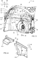
- eine perspektivische Explosionsdarstellung zweier einzelner Abdeckungsteile der Abdeckung gemäß
Fig. 2 , - Fig. 5
- eine perspektivische Darstellung mehrerer Abdeckungsteile der Abdeckung gemäß
Fig. 3 und zugehörigen Montageteilen im Bereich des Details VI, und - Fig. 6
- eine vergrößerte perspektivische Darstellung der Montageteile des Details VI gemäß
Fig. 5 . -
Fig. 1 zeigt einen Ausschnitt eines Traktors 10 im Bereich seiner Hinterachse 12 gemäß dem Stand der Technik. Ein kabinenseitiger Abschnitt 14 des Traktors 10 und ein tragstrukturseitiger Abschnitt 16 des Traktors 10 begrenzen im Bereich der Hinterachse 12 ein Radhaus 18 zur Aufnahme eines hier nicht dargestellten Hinterrades. Letzteres wird über seine Felge in üblicher Weise an einen Radflansch 20 der Hinterachse 12 montiert. Das dargestellte Radhaus 18 bietet insbesondere einen Spritzschutz gegenüber einer Kabine 22 des Traktors 10 und der Umgebung, z.B. auch Personen. - Die Kabine 22 weist unter anderem eine Seitenwand 24 auf, mit der ein Kotflügel 25 oder Schutzblech verbunden ist. Die Kabine 22 ist auf hier nicht im Einzelnen dargestellte Weise an einer Tragstruktur 26 des Traktors 10 beweglich oder unbeweglich gelagert. Aufgrund der konstruktionsmäßigen Ausgestaltung der Kabine 22 und der Tragstruktur 26 im Bereich der Hinterachse 12 weist das Radhaus 18 gemäß
Fig. 1 einen in einer Querrichtung 28 des Traktors 10 zugänglichen Spalt 30 auf. Im Bereich dieses offenen Spaltes 30 und angrenzenden Bereichen (z.B. eines Heckkrafthebers 32) kann sich deshalb im Arbeitseinsatz des Traktors 10 eine Ansammlung 34 von Schmutz, Schlamm, Erde und dergleichen bilden. Dies erfordert entsprechende Reinigungsarbeiten, z.B. an dem Heckkraftheber 32 und an Bauteilen des Traktors 10 im Bereich des Spaltes 30, wie etwa dort verlaufenden elektrischen und/oder hydraulischen Leitungen 36. - Um derartige Reinigungsarbeiten zu vermeiden oder zumindest zu reduzieren, ist der Spalt 30 gemäß
Fig. 2 mit einer Abdeckung 38 in Querrichtung 28 wirksam abgedeckt. Die Abdeckung 38 schließt den Spalt 30 zumindest teilweise. Entsprechend ist der Spalt 30 in Querrichtung 28 gar nicht oder nur noch teilweise geöffnet. Mit anderen Worten kann entlang der Querrichtung 28 signifikant weniger oder gar keine Ansammlung 34 von Schmutz und dergleichen in den Spalt 30 gelangen. - Die Abdeckung 38 ist einerseits teilweise kabinenseitig und andererseits teilweise tragstrukturseitig lösbar befestigt. Dabei weist die Abdeckung 38 mehrere Abdeckungsteile auf, beispielsweise die Abdeckungsteile 40-1, 40-2, 40-3, 40-4 gemäß
Fig. 2 . - Die Abdeckungsteile 40-1 und 40-2 sind jeweils tragstrukturseitig mittels einer oder mehrerer Fixierschrauben 42 lösbar befestigt. Vorzugsweise ist das Abdeckungsteil mittels lediglich einer Fixierschraube 42 befestigt, während das Abdeckungsteil 40-2 mittels der zwei sichtbaren Fixierschrauben 42 und weiterer Fixierschrauben 42 befestigt ist, welche in der Ansicht gemäß
Fig. 2 von einem die Hinterachse 12 umgebenden Öltank 44 verdeckt sind. Dieser Öltank 44 enthält Hydrauliköl für ein Hinterachs-Verteilergetriebe. - Die Abdeckungsteile 40-3 und 40-4 sind an einer oder mehreren Fixierleisten 46 lösbar oder unlösbar befestigt, beispielsweise mittels Fixierschrauben 42. Die Fixierleiste(n) 46 selbst wiederum ist/sind kabinenseitig lösbar oder unlösbar befestigt, beispielsweise ebenfalls mittels Fixierschrauben 42.
- Das dem Öltank 44 zugeordnete Radhaus 18 befindet sich entlang der Querrichtung 28 rechts, wenn die Blickrichtung einer parallel zur Längsrichtung 48 des Traktors 10 ausgerichteten Vorwärtsfahrtrichtung 50 entspricht. Das dem Öltank 44 in Querrichtung 28 gegenüberliegende Radhaus 18 ist mit einer Abdeckung 38 abgedeckt, welche im Gegensatz zur Ausführung gemäß
Fig. 2 kein Abdeckungsteil 40-2 aufweist. Dies liegt daran, dass an dem links angeordneten Radhaus 18 gemäßFig. 3 eine Außenwand 52 eines Brennstofftanks 54 des Traktors 10 angeordnet ist. Bei der Abdeckung 38 gemäßFig. 2 ersetzt das Abdeckungsteil 40-2 gewissermaßen die Außenwand 52 gemäßFig. 3 . - Die Abdeckung 38 ist im Montagezustand zumindest teilweise formschlüssig an einem kabinenseitigen Abschnitt 14 und/oder an einem tragstrukturseitigen Abschnitt 16 angeordnet. Die Formschlüssigkeit unterstützt eine fehlerfreie Positionierung der Abdeckung 38 am Radhaus 18 bzw. an dessen Spalt 30. Hierbei liegt das Abdeckungsteil 40-1 formschlüssig an einer Außenfläche des Öltanks 44 an (
Fig. 2 ). Bei der Ausführung gemäßFig. 3 liegt das Abdeckungsteil 40-1 formschlüssig an einer Außenfläche des Brennstofftanks 54 an. - Die Abdeckungsteile 40-3, 40-4 sind vorzugsweise aus einem elastischen Material (z.B. gummiartige Formteile oder Meterware) hergestellt. Die Abdeckungsteile 40-1, 40-2 sind vorzugsweise aus einem plastischen Material (z.B. Kunststoff) hergestellt. Eine elastische Ausgestaltung des Abdeckungsteiles 40-3 ermöglicht bedarfsweise eine einfache Demontage des Abdeckungsteiles 40-1, indem das elastische Abdeckungsteil 40-3 etwa entlang der Querrichtung 28 weggebogen wird, so dass das Abdeckungsteil 40-1 für eine Demontage entlang der Längsrichtung 48 befreit ist.
- Das kabinenseitig befestigte Abdeckungsteil 40-3 und das tragstrukturseitig befestigtes Abdeckungsteil 40-1 sind entlang einer Hochrichtung 56 des Traktors 10 in gegenseitiger beweglicher Überlappung angeordnet. Hierdurch bleibt der Spalt 30 auch geschlossen, wenn sich aufgrund der Fahrbedingungen extreme Relativbewegungen zwischen der Kabine 22 und der Tragstruktur 26 entlang der Hochrichtung 56 ergeben. Die Hochrichtung 56 ist etwa lotrecht zur Querrichtung 28 und zur Längsrichtung 48 angeordnet.
- In
Fig. 4 ist erkennbar, dass das Abdeckungsteil 40-1 ein Kupplungselement 58 trägt. Das Kupplungselement 58 ist nach Art eines etwa rechteckigen Rahmens ausgebildet, welcher sich in Längsrichtung 48 dem Abdeckungsteil 40-2 zugewandt konisch aufweitet. Das Kupplungselement 58 korrespondiert mit einem Gegenkupplungselement 60 nach Art einer in Längsrichtung 48 wirksamen mechanischen Kupplung. Das Gegenkupplungselement 60 greift im Montagezustand der Abdeckung 38 etwa formschlüssig in den Hohlraum des rahmenartigen Kupplungselementes 58 ein. Hierzu ist das zapfenartige Gegenkupplungselement 60 dem Kupplungselement58 zugewandt konisch verjüngt ausgebildet. Die Kupplung dient als eine Montagehilfe für eine fehlerfreie Positionierung des Abdeckungsteiles 40-1. Hierzu wird zunächst das Abdeckungsteil 40-2 tragstrukturseitig befestigt, so dass das Gegenkupplungselement 60 am Traktor unbeweglich fixiert ist. - Bei der Abdeckung 38 gemäß
Fig. 3 ist das Gegenkupplungselement 60 wegen des nicht vorhandenen Abdeckungsteiles 40-2 an der Tragstruktur 26 selbst, insbesondere an der Außenwand 52 befestigt und somit ebenfalls am Traktor 10 fixiert. Das an einer Außenfläche des Brennstofftanks 54 anzulegende Abdeckungsteil 40-1 mit einem Kupplungselement 58 wirkt dann während der Montage sinngemäß mit diesem Gegenkupplungselement 60 zusammen, wie anhand vonFig. 4 beschrieben. -
Fig. 5 zeigt im Bereich des Details VI eine Fixiervorrichtung 62 im demontierten Zustand. Sie weist unter anderem zwei noch zu beschreibende plattenartige Bauteile auf. Sie dient einerseits einer Bewegungsführung der kabinenseitig befestigten Abdeckungsteile 40-3, 40-4 entlang der Hochrichtung 56 und andererseits einer Bewegungsbegrenzung dieser Abdeckungsteile 40-3, 40-4 in Querrichtung 28. Die Bewegungsführung entlang der Hochrichtung 56 vermeidet etwaige Beeinträchtigungen der Abdeckung 38 bei Relativbewegungen zwischen der Kabine 22 und der Tragstruktur 26 in Hochrichtung 56. Die Bewegungsbegrenzung in Querrichtung 28 begrenzt den Abstand zwischen den Abdeckungsteilen 40-1 und 40-3 in Querrichtung 28, so dass über diesen Abstand keine nennenswerte Ansammlung 34 von Schmutz und dergleichen in den Spalt 30 gelangen kann. - Die Fixiervorrichtung 62 weist ein Begrenzungselement 64 auf, welches an der Tragstruktur 26 in Querrichtung 28 unbeweglich befestigt ist. Es hat einen sich in Querrichtung 28 erstreckenden zylindrischen Abschnitt 66, der an seinem Freiende einen Begrenzungsanschlag 68 trägt. Der scheibenförmige Begrenzungsanschlag 68 ist etwa lotrecht zur Querrichtung 28 ausgerichtet.
- Im Montagezustand der Fixiervorrichtung 62 ist eine Begrenzungsplatte 70 mit den Abdeckungsteilen 40-3, 40-4 verbunden und etwa lotrecht zur Querrichtung 28 ausgerichtet. Bei Bewegungen dieser Abdeckungsteile 40-3, 40-4 in Querrichtung 28 ist die Begrenzungsplatte 70 von dem Begrenzungsanschlag 68 flankiert. Letzterer begrenzt folglich Bewegungen der Begrenzungsplatte 70 und somit auch der Abdeckungsteile 40-3, 40-4 in Querrichtung 28.
- Die Begrenzungsplatte 70 weist eine etwa in Hochrichtung 56 verlaufende Plattenaussparung 72 auf, welche den Abschnitt 66 des Begrenzungselements 64 beweglich umgibt. Hierdurch ist im Montagezustand der Abdeckung 38 deren geführte Beweglichkeit gewährleistet, wenn Relativbewegungen zwischen der Kabine 22 und der Tragstruktur 26 auftreten.
- Im Montagezustand ist die Begrenzungsplatte 70 mit einer planparallelen Deckplatte 74 lösbar verbunden. Für diese Verbindung dienen vier Schrauben 76 und korrespondierende Schraubenmuttern 78. Die beiden Platten 70, 74 wirken dann nach Art zweier Klemmbacken, die zwischen sich das Abdeckungsteil 40-3 und das Abdeckungsteil 40-4 lösbar klemmfixieren. Diese Klemmfixierung verbindet die Abdeckungsteile 40-3, 40-4 im Montagezustand mit der Begrenzungsplatte 70.
- Die Deckplatte 74 deckt im Arbeitseinsatz des Traktors 10 die Plattenaussparung 72 in Querrichtung 28 wirksam ab, so dass im Bereich der Plattenaussparung 72 keine Ansammlung 34 von Schmutz und dergleichen in den Spalt 30 gelangen kann. In einem aneinander angrenzenden Bereich sind die beiden Abdeckungsteile 40-3 und 40-4 von Aussparungen 80, 82 durchsetzt (
Fig. 5 ), um die vorbeschriebene Funktionalität der Fixiervorrichtung 62 zu unterstützen. Die langlochartigen Aussparungen 82 ermöglichen eine Montagejustierung der Abdeckungsteile 40-3 und 40-4 entlang der Längsrichtung 48.
Claims (12)
- Traktor (10) mit einer Kabine (22) und mit einer Tragstruktur (26), an der eine entlang einer Querrichtung (28) verlaufende Hinterachse (12) des Traktors (10) gelagert ist,
wobei- mindestens ein kabinenseitiger Abschnitt (14) des Traktors (10) und mindestens ein tragstrukturseitiger Abschnitt (16) des Traktors (10) im Bereich der Hinterachse (12) ein Radhaus (18) für ein Hinterrad begrenzen, und- das Radhaus (18) einen Spalt (30) aufweist, welcher mittels einer Abdeckung (38) zumindest in Querrichtung (28) wirksam abgedeckt ist. - Traktor nach Anspruch 1, dadurch gekennzeichnet, dass die Abdeckung (38) lösbar befestigt ist.
- Traktor nach Anspruch 1 oder 2, dadurch gekennzeichnet, dass die Abdeckung (38) kabinenseitig (22) und/oder tragstrukturseitig (26) befestigt ist.
- Traktor nach einem der vorhergehenden Ansprüche, dadurch gekennzeichnet, dass die Abdeckung (38) mehrere Abdeckungsteile (40-1, 40-2, 40-3, 40-4) aufweist, welche einzeln kabinenseitig (22) und/oder tragstrukturseitig (26) befestigbar sind.
- Traktor nach Anspruch 4, dadurch gekennzeichnet, dass mindestens ein Abdeckungsteil (40-3, 40-4) elastisch ausgebildet ist.
- Traktor nach Anspruch 4 oder 5, dadurch gekennzeichnet, dass ein kabinenseitig (22) befestigtes Abdeckungsteil (40-3) und ein tragstrukturseitig (26) befestigtes Abdeckungsteil (40-1) entlang einer Hochrichtung (56) des Traktors (10) in gegenseitiger beweglicher Überlappung angeordnet sind.
- Traktor nach einem der vorhergehenden Ansprüche, dadurch gekennzeichnet, dass die Abdeckung (38) im Montagezustand zumindest teilweise formschlüssig an einem kabinenseitigen (22) und/oder tragstrukturseitigen (26) Bestandteil des Traktors (10) angeordnet ist.
- Traktor nach einem der Ansprüche 4 bis 7, dadurch gekennzeichnet, dass ein Abdeckungsteil (40-1) ein Kupplungselement (58) trägt, welches mit einem am Traktor (10) fixierten Gegenkupplungselement (60) nach Art einer in Längsrichtung (48) des Traktors (10) wirksamen mechanischen Kupplung korrespondiert.
- Traktor nach einem der Ansprüche 4 bis 8, dadurch gekennzeichnet, dass ein tragstrukturseitig (26) befestigtes Begrenzungselement (64) einen etwa lotrecht zur Querrichtung (28) des Traktors (10) ausgerichteten Begrenzungsanschlag (68) aufweist zur Begrenzung von Bewegungen mindestens eines Abdeckungsteiles (40-3, 40-4) in Querrichtung (28) .
- Traktor nach Anspruch 9, dadurch gekennzeichnet, dass der Begrenzungsanschlag (68) eine etwa lotrecht zur Querrichtung (28) des Traktors (10) ausgerichtete Begrenzungsplatte (70) flankiert, welche mit mindestens einem Abdeckungsteil (40-3, 40-4) verbunden ist.
- Traktor nach Anspruch 10, dadurch gekennzeichnet, dass die Begrenzungsplatte (70) eine etwa in Hochrichtung (56) des Traktors (10) verlaufende Plattenaussparung (72) aufweist, welche das Begrenzungselement (64) für eine Relativbeweglichkeit etwa entlang der Hochrichtung (56) beweglich umgibt.
- Traktor nach Anspruch 10 oder 11, dadurch gekennzeichnet, dass die Begrenzungsplatte (70) und eine Deckplatte (74) miteinander lösbar verbunden sind und nach Art zweier Klemmbacken zwischen sich mindestens ein Abdeckungsteil (40-3, 40-4) klemmfixieren.
Applications Claiming Priority (1)
| Application Number | Priority Date | Filing Date | Title |
|---|---|---|---|
| DE102019210327.8A DE102019210327A1 (de) | 2019-07-12 | 2019-07-12 | Traktor mit Radhaus |
Publications (2)
| Publication Number | Publication Date |
|---|---|
| EP3763605A1 true EP3763605A1 (de) | 2021-01-13 |
| EP3763605B1 EP3763605B1 (de) | 2022-09-28 |
Family
ID=71574923
Family Applications (1)
| Application Number | Title | Priority Date | Filing Date |
|---|---|---|---|
| EP20183252.4A Active EP3763605B1 (de) | 2019-07-12 | 2020-06-30 | Traktor mit radhaus |
Country Status (4)
| Country | Link |
|---|---|
| US (1) | US11787479B2 (de) |
| EP (1) | EP3763605B1 (de) |
| DE (1) | DE102019210327A1 (de) |
| FI (1) | FI3763605T3 (de) |
Citations (3)
| Publication number | Priority date | Publication date | Assignee | Title |
|---|---|---|---|---|
| EP0672577A2 (de) * | 1994-03-18 | 1995-09-20 | Nicholas Maxwell Strong | Spritzwasserabweiser |
| EP1288114A2 (de) * | 2001-08-29 | 2003-03-05 | Deere & Company | Nutzfahrzeug |
| JP2010264927A (ja) * | 2009-05-15 | 2010-11-25 | Yanmar Co Ltd | 作業車両のフェンダカバー取付構造 |
Family Cites Families (6)
| Publication number | Priority date | Publication date | Assignee | Title |
|---|---|---|---|---|
| US5184832A (en) * | 1984-12-07 | 1993-02-09 | Tsutomu Miwa | Aerodynamic motorcar |
| US8979102B1 (en) * | 2013-11-27 | 2015-03-17 | Michael Prentice | Retractable wheel fairings for motor vehicles |
| JP6496180B2 (ja) * | 2014-10-24 | 2019-04-03 | ヤンマー株式会社 | トラクタ |
| WO2016075573A1 (en) * | 2014-11-12 | 2016-05-19 | Same Deutz-Fahr Group S.P.A. | Tractor with movable mudguard device |
| DE102015222174B4 (de) * | 2015-11-11 | 2024-11-28 | Bayerische Motoren Werke Aktiengesellschaft | Radhausabdeckung für eine Kraftfahrzeugkarosserie und hiermit ausgestattetes Kraftfahrzeug |
| US10407110B2 (en) * | 2017-10-27 | 2019-09-10 | Naade, Inc. | Motor vehicle fender |
-
2019
- 2019-07-12 DE DE102019210327.8A patent/DE102019210327A1/de not_active Withdrawn
-
2020
- 2020-06-30 EP EP20183252.4A patent/EP3763605B1/de active Active
- 2020-06-30 FI FIEP20183252.4T patent/FI3763605T3/de active
- 2020-06-30 US US16/946,656 patent/US11787479B2/en active Active
Patent Citations (3)
| Publication number | Priority date | Publication date | Assignee | Title |
|---|---|---|---|---|
| EP0672577A2 (de) * | 1994-03-18 | 1995-09-20 | Nicholas Maxwell Strong | Spritzwasserabweiser |
| EP1288114A2 (de) * | 2001-08-29 | 2003-03-05 | Deere & Company | Nutzfahrzeug |
| JP2010264927A (ja) * | 2009-05-15 | 2010-11-25 | Yanmar Co Ltd | 作業車両のフェンダカバー取付構造 |
Also Published As
| Publication number | Publication date |
|---|---|
| DE102019210327A1 (de) | 2021-01-14 |
| FI3763605T3 (en) | 2022-12-15 |
| US11787479B2 (en) | 2023-10-17 |
| EP3763605B1 (de) | 2022-09-28 |
| US20210009207A1 (en) | 2021-01-14 |
Similar Documents
| Publication | Publication Date | Title |
|---|---|---|
| DE3205979C2 (de) | Lenkachse mit Hilfskraftunterstützung | |
| WO2018192913A1 (de) | Befestigungsanordnung für eine fahrzeugbatterie an einer karosserie eines kraftfahrzeugs sowie verfahren zur montage einer fahrzeugbatterie in einem kraftfahrzeug | |
| EP0601286A1 (de) | Tür für ein Kraftfahrzeug | |
| EP1880926B1 (de) | Kraftfahrzeug mit einem Cockpitmodul | |
| DE20303315U1 (de) | Torantriebsgehäuse | |
| EP3158842A1 (de) | Landwirtschaftliches fahrzeug | |
| EP1870324A2 (de) | Kettenfahrwerk | |
| DE102018104768A1 (de) | Aktuator mit rückensteifer Kette | |
| DE202017102398U1 (de) | Montageeinrichtung für Hubstützen | |
| EP3079969B1 (de) | Anbindung eines frontends eines kraftfahrzeugs an einen hilfsrahmen des kraftfahrzeugs | |
| DE102016118889A1 (de) | Vorrichtung zur Befestigung eines Luftleitmittels an einem Kraftfahrzeug | |
| EP3763605B1 (de) | Traktor mit radhaus | |
| DE102018008632A1 (de) | "Spoilerantrieb" | |
| EP2986475B1 (de) | Vorrichtung mit einer kameraeinheit und einem doppelwandigen gehäuse | |
| DE69408124T2 (de) | Fahrgestell für einen autobus | |
| DE102013202076B4 (de) | Stützvorrichtung mit Montageeinheit | |
| DE102007019935A1 (de) | Befestigungsanordnung mit einem Stoßfänger und einem Kotflügel für ein Kraftfahrzeug | |
| DE102011117326A1 (de) | Anordnung eines Außenanbauelements an einem Montageträgerelement eines Kraftwagens | |
| DE102019120166B4 (de) | Geländegängiges Fahrzeug, insbesondere Pick-Up | |
| DE102009024783A1 (de) | Befestigungsanordnung einer Leuchteinheit an einem Verkleidungsteil | |
| DE102014005731A1 (de) | Aggregateraumabdeckung für einen Kraftwagen | |
| DE102014103541A1 (de) | Baugruppe für ein Kraftfahrzeug und Verfahren zum Verbinden eines Karosserieteils mit einem Spoiler | |
| DE102017006694A1 (de) | Stützvorrichtung für eine Rückwandtür eines Fahrzeugs | |
| DE60026812T2 (de) | Feststellbremsgehäuse für ein Kraftfahrzeug und Montageverfahren dieses Gehäuses | |
| DE102006039012B4 (de) | Verbindungsanordnung eines Querträgers an einem tragenden Bauteil eines Lastkraftwagens |
Legal Events
| Date | Code | Title | Description |
|---|---|---|---|
| PUAI | Public reference made under article 153(3) epc to a published international application that has entered the european phase |
Free format text: ORIGINAL CODE: 0009012 |
|
| STAA | Information on the status of an ep patent application or granted ep patent |
Free format text: STATUS: THE APPLICATION HAS BEEN PUBLISHED |
|
| AK | Designated contracting states |
Kind code of ref document: A1 Designated state(s): AL AT BE BG CH CY CZ DE DK EE ES FI FR GB GR HR HU IE IS IT LI LT LU LV MC MK MT NL NO PL PT RO RS SE SI SK SM TR |
|
| AX | Request for extension of the european patent |
Extension state: BA ME |
|
| STAA | Information on the status of an ep patent application or granted ep patent |
Free format text: STATUS: REQUEST FOR EXAMINATION WAS MADE |
|
| 17P | Request for examination filed |
Effective date: 20210713 |
|
| RBV | Designated contracting states (corrected) |
Designated state(s): AL AT BE BG CH CY CZ DE DK EE ES FI FR GB GR HR HU IE IS IT LI LT LU LV MC MK MT NL NO PL PT RO RS SE SI SK SM TR |
|
| GRAP | Despatch of communication of intention to grant a patent |
Free format text: ORIGINAL CODE: EPIDOSNIGR1 |
|
| RIC1 | Information provided on ipc code assigned before grant |
Ipc: B62D 25/16 20060101ALI20220412BHEP Ipc: B62D 25/18 20060101AFI20220412BHEP |
|
| STAA | Information on the status of an ep patent application or granted ep patent |
Free format text: STATUS: GRANT OF PATENT IS INTENDED |
|
| INTG | Intention to grant announced |
Effective date: 20220519 |
|
| GRAS | Grant fee paid |
Free format text: ORIGINAL CODE: EPIDOSNIGR3 |
|
| GRAA | (expected) grant |
Free format text: ORIGINAL CODE: 0009210 |
|
| STAA | Information on the status of an ep patent application or granted ep patent |
Free format text: STATUS: THE PATENT HAS BEEN GRANTED |
|
| AK | Designated contracting states |
Kind code of ref document: B1 Designated state(s): AL AT BE BG CH CY CZ DE DK EE ES FI FR GB GR HR HU IE IS IT LI LT LU LV MC MK MT NL NO PL PT RO RS SE SI SK SM TR |
|
| REG | Reference to a national code |
Ref country code: GB Ref legal event code: FG4D Free format text: NOT ENGLISH |
|
| REG | Reference to a national code |
Ref country code: CH Ref legal event code: EP |
|
| REG | Reference to a national code |
Ref country code: AT Ref legal event code: REF Ref document number: 1521082 Country of ref document: AT Kind code of ref document: T Effective date: 20221015 |
|
| REG | Reference to a national code |
Ref country code: DE Ref legal event code: R096 Ref document number: 502020001767 Country of ref document: DE |
|
| REG | Reference to a national code |
Ref country code: IE Ref legal event code: FG4D Free format text: LANGUAGE OF EP DOCUMENT: GERMAN |
|
| REG | Reference to a national code |
Ref country code: LT Ref legal event code: MG9D |
|
| PG25 | Lapsed in a contracting state [announced via postgrant information from national office to epo] |
Ref country code: SE Free format text: LAPSE BECAUSE OF FAILURE TO SUBMIT A TRANSLATION OF THE DESCRIPTION OR TO PAY THE FEE WITHIN THE PRESCRIBED TIME-LIMIT Effective date: 20220928 Ref country code: RS Free format text: LAPSE BECAUSE OF FAILURE TO SUBMIT A TRANSLATION OF THE DESCRIPTION OR TO PAY THE FEE WITHIN THE PRESCRIBED TIME-LIMIT Effective date: 20220928 Ref country code: NO Free format text: LAPSE BECAUSE OF FAILURE TO SUBMIT A TRANSLATION OF THE DESCRIPTION OR TO PAY THE FEE WITHIN THE PRESCRIBED TIME-LIMIT Effective date: 20221228 Ref country code: LV Free format text: LAPSE BECAUSE OF FAILURE TO SUBMIT A TRANSLATION OF THE DESCRIPTION OR TO PAY THE FEE WITHIN THE PRESCRIBED TIME-LIMIT Effective date: 20220928 Ref country code: LT Free format text: LAPSE BECAUSE OF FAILURE TO SUBMIT A TRANSLATION OF THE DESCRIPTION OR TO PAY THE FEE WITHIN THE PRESCRIBED TIME-LIMIT Effective date: 20220928 |
|
| REG | Reference to a national code |
Ref country code: NL Ref legal event code: MP Effective date: 20220928 |
|
| PG25 | Lapsed in a contracting state [announced via postgrant information from national office to epo] |
Ref country code: HR Free format text: LAPSE BECAUSE OF FAILURE TO SUBMIT A TRANSLATION OF THE DESCRIPTION OR TO PAY THE FEE WITHIN THE PRESCRIBED TIME-LIMIT Effective date: 20220928 Ref country code: GR Free format text: LAPSE BECAUSE OF FAILURE TO SUBMIT A TRANSLATION OF THE DESCRIPTION OR TO PAY THE FEE WITHIN THE PRESCRIBED TIME-LIMIT Effective date: 20221229 |
|
| PG25 | Lapsed in a contracting state [announced via postgrant information from national office to epo] |
Ref country code: SM Free format text: LAPSE BECAUSE OF FAILURE TO SUBMIT A TRANSLATION OF THE DESCRIPTION OR TO PAY THE FEE WITHIN THE PRESCRIBED TIME-LIMIT Effective date: 20220928 Ref country code: RO Free format text: LAPSE BECAUSE OF FAILURE TO SUBMIT A TRANSLATION OF THE DESCRIPTION OR TO PAY THE FEE WITHIN THE PRESCRIBED TIME-LIMIT Effective date: 20220928 Ref country code: PT Free format text: LAPSE BECAUSE OF FAILURE TO SUBMIT A TRANSLATION OF THE DESCRIPTION OR TO PAY THE FEE WITHIN THE PRESCRIBED TIME-LIMIT Effective date: 20230130 Ref country code: ES Free format text: LAPSE BECAUSE OF FAILURE TO SUBMIT A TRANSLATION OF THE DESCRIPTION OR TO PAY THE FEE WITHIN THE PRESCRIBED TIME-LIMIT Effective date: 20220928 Ref country code: CZ Free format text: LAPSE BECAUSE OF FAILURE TO SUBMIT A TRANSLATION OF THE DESCRIPTION OR TO PAY THE FEE WITHIN THE PRESCRIBED TIME-LIMIT Effective date: 20220928 |
|
| PG25 | Lapsed in a contracting state [announced via postgrant information from national office to epo] |
Ref country code: SK Free format text: LAPSE BECAUSE OF FAILURE TO SUBMIT A TRANSLATION OF THE DESCRIPTION OR TO PAY THE FEE WITHIN THE PRESCRIBED TIME-LIMIT Effective date: 20220928 Ref country code: PL Free format text: LAPSE BECAUSE OF FAILURE TO SUBMIT A TRANSLATION OF THE DESCRIPTION OR TO PAY THE FEE WITHIN THE PRESCRIBED TIME-LIMIT Effective date: 20220928 Ref country code: IS Free format text: LAPSE BECAUSE OF FAILURE TO SUBMIT A TRANSLATION OF THE DESCRIPTION OR TO PAY THE FEE WITHIN THE PRESCRIBED TIME-LIMIT Effective date: 20230128 Ref country code: EE Free format text: LAPSE BECAUSE OF FAILURE TO SUBMIT A TRANSLATION OF THE DESCRIPTION OR TO PAY THE FEE WITHIN THE PRESCRIBED TIME-LIMIT Effective date: 20220928 |
|
| REG | Reference to a national code |
Ref country code: DE Ref legal event code: R097 Ref document number: 502020001767 Country of ref document: DE |
|
| PG25 | Lapsed in a contracting state [announced via postgrant information from national office to epo] |
Ref country code: NL Free format text: LAPSE BECAUSE OF FAILURE TO SUBMIT A TRANSLATION OF THE DESCRIPTION OR TO PAY THE FEE WITHIN THE PRESCRIBED TIME-LIMIT Effective date: 20220928 Ref country code: AL Free format text: LAPSE BECAUSE OF FAILURE TO SUBMIT A TRANSLATION OF THE DESCRIPTION OR TO PAY THE FEE WITHIN THE PRESCRIBED TIME-LIMIT Effective date: 20220928 |
|
| PG25 | Lapsed in a contracting state [announced via postgrant information from national office to epo] |
Ref country code: DK Free format text: LAPSE BECAUSE OF FAILURE TO SUBMIT A TRANSLATION OF THE DESCRIPTION OR TO PAY THE FEE WITHIN THE PRESCRIBED TIME-LIMIT Effective date: 20220928 |
|
| PLBE | No opposition filed within time limit |
Free format text: ORIGINAL CODE: 0009261 |
|
| STAA | Information on the status of an ep patent application or granted ep patent |
Free format text: STATUS: NO OPPOSITION FILED WITHIN TIME LIMIT |
|
| 26N | No opposition filed |
Effective date: 20230629 |
|
| PG25 | Lapsed in a contracting state [announced via postgrant information from national office to epo] |
Ref country code: SI Free format text: LAPSE BECAUSE OF FAILURE TO SUBMIT A TRANSLATION OF THE DESCRIPTION OR TO PAY THE FEE WITHIN THE PRESCRIBED TIME-LIMIT Effective date: 20220928 |
|
| PG25 | Lapsed in a contracting state [announced via postgrant information from national office to epo] |
Ref country code: MC Free format text: LAPSE BECAUSE OF FAILURE TO SUBMIT A TRANSLATION OF THE DESCRIPTION OR TO PAY THE FEE WITHIN THE PRESCRIBED TIME-LIMIT Effective date: 20220928 |
|
| PG25 | Lapsed in a contracting state [announced via postgrant information from national office to epo] |
Ref country code: MC Free format text: LAPSE BECAUSE OF FAILURE TO SUBMIT A TRANSLATION OF THE DESCRIPTION OR TO PAY THE FEE WITHIN THE PRESCRIBED TIME-LIMIT Effective date: 20220928 |
|
| REG | Reference to a national code |
Ref country code: CH Ref legal event code: PL |
|
| REG | Reference to a national code |
Ref country code: BE Ref legal event code: MM Effective date: 20230630 |
|
| PG25 | Lapsed in a contracting state [announced via postgrant information from national office to epo] |
Ref country code: LU Free format text: LAPSE BECAUSE OF NON-PAYMENT OF DUE FEES Effective date: 20230630 |
|
| REG | Reference to a national code |
Ref country code: IE Ref legal event code: MM4A |
|
| PG25 | Lapsed in a contracting state [announced via postgrant information from national office to epo] |
Ref country code: LU Free format text: LAPSE BECAUSE OF NON-PAYMENT OF DUE FEES Effective date: 20230630 |
|
| PG25 | Lapsed in a contracting state [announced via postgrant information from national office to epo] |
Ref country code: IE Free format text: LAPSE BECAUSE OF NON-PAYMENT OF DUE FEES Effective date: 20230630 |
|
| PG25 | Lapsed in a contracting state [announced via postgrant information from national office to epo] |
Ref country code: IE Free format text: LAPSE BECAUSE OF NON-PAYMENT OF DUE FEES Effective date: 20230630 Ref country code: CH Free format text: LAPSE BECAUSE OF NON-PAYMENT OF DUE FEES Effective date: 20230630 |
|
| PG25 | Lapsed in a contracting state [announced via postgrant information from national office to epo] |
Ref country code: BE Free format text: LAPSE BECAUSE OF NON-PAYMENT OF DUE FEES Effective date: 20230630 |
|
| PG25 | Lapsed in a contracting state [announced via postgrant information from national office to epo] |
Ref country code: BG Free format text: LAPSE BECAUSE OF FAILURE TO SUBMIT A TRANSLATION OF THE DESCRIPTION OR TO PAY THE FEE WITHIN THE PRESCRIBED TIME-LIMIT Effective date: 20220928 |
|
| PG25 | Lapsed in a contracting state [announced via postgrant information from national office to epo] |
Ref country code: BG Free format text: LAPSE BECAUSE OF FAILURE TO SUBMIT A TRANSLATION OF THE DESCRIPTION OR TO PAY THE FEE WITHIN THE PRESCRIBED TIME-LIMIT Effective date: 20220928 |
|
| GBPC | Gb: european patent ceased through non-payment of renewal fee |
Effective date: 20240630 |
|
| PG25 | Lapsed in a contracting state [announced via postgrant information from national office to epo] |
Ref country code: GB Free format text: LAPSE BECAUSE OF NON-PAYMENT OF DUE FEES Effective date: 20240630 |
|
| PGFP | Annual fee paid to national office [announced via postgrant information from national office to epo] |
Ref country code: FI Payment date: 20250625 Year of fee payment: 6 |
|
| PGFP | Annual fee paid to national office [announced via postgrant information from national office to epo] |
Ref country code: DE Payment date: 20250521 Year of fee payment: 6 |
|
| PGFP | Annual fee paid to national office [announced via postgrant information from national office to epo] |
Ref country code: FR Payment date: 20250625 Year of fee payment: 6 |
|
| PGFP | Annual fee paid to national office [announced via postgrant information from national office to epo] |
Ref country code: AT Payment date: 20250721 Year of fee payment: 5 |
|
| PG25 | Lapsed in a contracting state [announced via postgrant information from national office to epo] |
Ref country code: CY Free format text: LAPSE BECAUSE OF FAILURE TO SUBMIT A TRANSLATION OF THE DESCRIPTION OR TO PAY THE FEE WITHIN THE PRESCRIBED TIME-LIMIT; INVALID AB INITIO Effective date: 20200630 |
|
| PG25 | Lapsed in a contracting state [announced via postgrant information from national office to epo] |
Ref country code: HU Free format text: LAPSE BECAUSE OF FAILURE TO SUBMIT A TRANSLATION OF THE DESCRIPTION OR TO PAY THE FEE WITHIN THE PRESCRIBED TIME-LIMIT; INVALID AB INITIO Effective date: 20200630 |
|
| PGFP | Annual fee paid to national office [announced via postgrant information from national office to epo] |
Ref country code: IT Payment date: 20250619 Year of fee payment: 6 |
|
| PG25 | Lapsed in a contracting state [announced via postgrant information from national office to epo] |
Ref country code: TR Free format text: LAPSE BECAUSE OF FAILURE TO SUBMIT A TRANSLATION OF THE DESCRIPTION OR TO PAY THE FEE WITHIN THE PRESCRIBED TIME-LIMIT Effective date: 20220928 |