EP3763589A1 - Verfahren, vorrichtungen und medien für autonom fahrende fahrzeuge - Google Patents
Verfahren, vorrichtungen und medien für autonom fahrende fahrzeuge Download PDFInfo
- Publication number
- EP3763589A1 EP3763589A1 EP20165984.4A EP20165984A EP3763589A1 EP 3763589 A1 EP3763589 A1 EP 3763589A1 EP 20165984 A EP20165984 A EP 20165984A EP 3763589 A1 EP3763589 A1 EP 3763589A1
- Authority
- EP
- European Patent Office
- Prior art keywords
- curvature
- spiral line
- real
- cur
- current vehicle
- Prior art date
- Legal status (The legal status is an assumption and is not a legal conclusion. Google has not performed a legal analysis and makes no representation as to the accuracy of the status listed.)
- Pending
Links
- 238000000034 method Methods 0.000 title claims abstract description 39
- 230000033001 locomotion Effects 0.000 claims abstract description 61
- 238000012937 correction Methods 0.000 claims description 14
- 230000004044 response Effects 0.000 claims description 11
- 238000003860 storage Methods 0.000 claims description 9
- 238000004590 computer program Methods 0.000 claims description 6
- 238000010586 diagram Methods 0.000 description 8
- 230000015654 memory Effects 0.000 description 7
- 238000004422 calculation algorithm Methods 0.000 description 6
- 238000004364 calculation method Methods 0.000 description 4
- 230000006870 function Effects 0.000 description 4
- 238000005516 engineering process Methods 0.000 description 3
- 238000004519 manufacturing process Methods 0.000 description 3
- 230000000116 mitigating effect Effects 0.000 description 3
- 238000004904 shortening Methods 0.000 description 3
- 238000004891 communication Methods 0.000 description 2
- 239000000463 material Substances 0.000 description 2
- 230000008569 process Effects 0.000 description 2
- 230000001133 acceleration Effects 0.000 description 1
- 230000003044 adaptive effect Effects 0.000 description 1
- 238000013473 artificial intelligence Methods 0.000 description 1
- 230000007547 defect Effects 0.000 description 1
- 238000005259 measurement Methods 0.000 description 1
- 238000012986 modification Methods 0.000 description 1
- 230000004048 modification Effects 0.000 description 1
- 239000013307 optical fiber Substances 0.000 description 1
- 238000005457 optimization Methods 0.000 description 1
- 238000003909 pattern recognition Methods 0.000 description 1
- 238000007639 printing Methods 0.000 description 1
- 238000012545 processing Methods 0.000 description 1
- 230000001902 propagating effect Effects 0.000 description 1
- 230000000007 visual effect Effects 0.000 description 1
Images


Classifications
-
- B—PERFORMING OPERATIONS; TRANSPORTING
- B60—VEHICLES IN GENERAL
- B60W—CONJOINT CONTROL OF VEHICLE SUB-UNITS OF DIFFERENT TYPE OR DIFFERENT FUNCTION; CONTROL SYSTEMS SPECIALLY ADAPTED FOR HYBRID VEHICLES; ROAD VEHICLE DRIVE CONTROL SYSTEMS FOR PURPOSES NOT RELATED TO THE CONTROL OF A PARTICULAR SUB-UNIT
- B60W30/00—Purposes of road vehicle drive control systems not related to the control of a particular sub-unit, e.g. of systems using conjoint control of vehicle sub-units, or advanced driver assistance systems for ensuring comfort, stability and safety or drive control systems for propelling or retarding the vehicle
- B60W30/18—Propelling the vehicle
- B60W30/18009—Propelling the vehicle related to particular drive situations
- B60W30/18163—Lane change; Overtaking manoeuvres
-
- B—PERFORMING OPERATIONS; TRANSPORTING
- B62—LAND VEHICLES FOR TRAVELLING OTHERWISE THAN ON RAILS
- B62D—MOTOR VEHICLES; TRAILERS
- B62D15/00—Steering not otherwise provided for
- B62D15/02—Steering position indicators ; Steering position determination; Steering aids
- B62D15/021—Determination of steering angle
-
- G—PHYSICS
- G05—CONTROLLING; REGULATING
- G05D—SYSTEMS FOR CONTROLLING OR REGULATING NON-ELECTRIC VARIABLES
- G05D1/00—Control of position, course or altitude of land, water, air, or space vehicles, e.g. automatic pilot
- G05D1/02—Control of position or course in two dimensions
- G05D1/021—Control of position or course in two dimensions specially adapted to land vehicles
- G05D1/0212—Control of position or course in two dimensions specially adapted to land vehicles with means for defining a desired trajectory
- G05D1/0221—Control of position or course in two dimensions specially adapted to land vehicles with means for defining a desired trajectory involving a learning process
-
- B—PERFORMING OPERATIONS; TRANSPORTING
- B60—VEHICLES IN GENERAL
- B60W—CONJOINT CONTROL OF VEHICLE SUB-UNITS OF DIFFERENT TYPE OR DIFFERENT FUNCTION; CONTROL SYSTEMS SPECIALLY ADAPTED FOR HYBRID VEHICLES; ROAD VEHICLE DRIVE CONTROL SYSTEMS FOR PURPOSES NOT RELATED TO THE CONTROL OF A PARTICULAR SUB-UNIT
- B60W30/00—Purposes of road vehicle drive control systems not related to the control of a particular sub-unit, e.g. of systems using conjoint control of vehicle sub-units, or advanced driver assistance systems for ensuring comfort, stability and safety or drive control systems for propelling or retarding the vehicle
- B60W30/10—Path keeping
- B60W30/12—Lane keeping
-
- B—PERFORMING OPERATIONS; TRANSPORTING
- B60—VEHICLES IN GENERAL
- B60W—CONJOINT CONTROL OF VEHICLE SUB-UNITS OF DIFFERENT TYPE OR DIFFERENT FUNCTION; CONTROL SYSTEMS SPECIALLY ADAPTED FOR HYBRID VEHICLES; ROAD VEHICLE DRIVE CONTROL SYSTEMS FOR PURPOSES NOT RELATED TO THE CONTROL OF A PARTICULAR SUB-UNIT
- B60W40/00—Estimation or calculation of non-directly measurable driving parameters for road vehicle drive control systems not related to the control of a particular sub unit, e.g. by using mathematical models
- B60W40/02—Estimation or calculation of non-directly measurable driving parameters for road vehicle drive control systems not related to the control of a particular sub unit, e.g. by using mathematical models related to ambient conditions
- B60W40/06—Road conditions
- B60W40/072—Curvature of the road
-
- B—PERFORMING OPERATIONS; TRANSPORTING
- B60—VEHICLES IN GENERAL
- B60W—CONJOINT CONTROL OF VEHICLE SUB-UNITS OF DIFFERENT TYPE OR DIFFERENT FUNCTION; CONTROL SYSTEMS SPECIALLY ADAPTED FOR HYBRID VEHICLES; ROAD VEHICLE DRIVE CONTROL SYSTEMS FOR PURPOSES NOT RELATED TO THE CONTROL OF A PARTICULAR SUB-UNIT
- B60W60/00—Drive control systems specially adapted for autonomous road vehicles
- B60W60/001—Planning or execution of driving tasks
-
- B—PERFORMING OPERATIONS; TRANSPORTING
- B62—LAND VEHICLES FOR TRAVELLING OTHERWISE THAN ON RAILS
- B62D—MOTOR VEHICLES; TRAILERS
- B62D15/00—Steering not otherwise provided for
- B62D15/02—Steering position indicators ; Steering position determination; Steering aids
- B62D15/025—Active steering aids, e.g. helping the driver by actively influencing the steering system after environment evaluation
-
- G—PHYSICS
- G05—CONTROLLING; REGULATING
- G05D—SYSTEMS FOR CONTROLLING OR REGULATING NON-ELECTRIC VARIABLES
- G05D1/00—Control of position, course or altitude of land, water, air, or space vehicles, e.g. automatic pilot
- G05D1/02—Control of position or course in two dimensions
- G05D1/021—Control of position or course in two dimensions specially adapted to land vehicles
- G05D1/0212—Control of position or course in two dimensions specially adapted to land vehicles with means for defining a desired trajectory
- G05D1/0223—Control of position or course in two dimensions specially adapted to land vehicles with means for defining a desired trajectory involving speed control of the vehicle
-
- G—PHYSICS
- G05—CONTROLLING; REGULATING
- G05D—SYSTEMS FOR CONTROLLING OR REGULATING NON-ELECTRIC VARIABLES
- G05D1/00—Control of position, course or altitude of land, water, air, or space vehicles, e.g. automatic pilot
- G05D1/02—Control of position or course in two dimensions
- G05D1/021—Control of position or course in two dimensions specially adapted to land vehicles
- G05D1/0231—Control of position or course in two dimensions specially adapted to land vehicles using optical position detecting means
- G05D1/0242—Control of position or course in two dimensions specially adapted to land vehicles using optical position detecting means using non-visible light signals, e.g. IR or UV signals
-
- G—PHYSICS
- G05—CONTROLLING; REGULATING
- G05D—SYSTEMS FOR CONTROLLING OR REGULATING NON-ELECTRIC VARIABLES
- G05D1/00—Control of position, course or altitude of land, water, air, or space vehicles, e.g. automatic pilot
- G05D1/02—Control of position or course in two dimensions
- G05D1/021—Control of position or course in two dimensions specially adapted to land vehicles
- G05D1/0231—Control of position or course in two dimensions specially adapted to land vehicles using optical position detecting means
- G05D1/0246—Control of position or course in two dimensions specially adapted to land vehicles using optical position detecting means using a video camera in combination with image processing means
- G05D1/0253—Control of position or course in two dimensions specially adapted to land vehicles using optical position detecting means using a video camera in combination with image processing means extracting relative motion information from a plurality of images taken successively, e.g. visual odometry, optical flow
-
- G—PHYSICS
- G05—CONTROLLING; REGULATING
- G05D—SYSTEMS FOR CONTROLLING OR REGULATING NON-ELECTRIC VARIABLES
- G05D1/00—Control of position, course or altitude of land, water, air, or space vehicles, e.g. automatic pilot
- G05D1/02—Control of position or course in two dimensions
- G05D1/021—Control of position or course in two dimensions specially adapted to land vehicles
- G05D1/0276—Control of position or course in two dimensions specially adapted to land vehicles using signals provided by a source external to the vehicle
-
- G—PHYSICS
- G06—COMPUTING; CALCULATING OR COUNTING
- G06V—IMAGE OR VIDEO RECOGNITION OR UNDERSTANDING
- G06V20/00—Scenes; Scene-specific elements
- G06V20/50—Context or environment of the image
- G06V20/56—Context or environment of the image exterior to a vehicle by using sensors mounted on the vehicle
- G06V20/588—Recognition of the road, e.g. of lane markings; Recognition of the vehicle driving pattern in relation to the road
-
- B—PERFORMING OPERATIONS; TRANSPORTING
- B60—VEHICLES IN GENERAL
- B60W—CONJOINT CONTROL OF VEHICLE SUB-UNITS OF DIFFERENT TYPE OR DIFFERENT FUNCTION; CONTROL SYSTEMS SPECIALLY ADAPTED FOR HYBRID VEHICLES; ROAD VEHICLE DRIVE CONTROL SYSTEMS FOR PURPOSES NOT RELATED TO THE CONTROL OF A PARTICULAR SUB-UNIT
- B60W2520/00—Input parameters relating to overall vehicle dynamics
- B60W2520/10—Longitudinal speed
-
- B—PERFORMING OPERATIONS; TRANSPORTING
- B60—VEHICLES IN GENERAL
- B60W—CONJOINT CONTROL OF VEHICLE SUB-UNITS OF DIFFERENT TYPE OR DIFFERENT FUNCTION; CONTROL SYSTEMS SPECIALLY ADAPTED FOR HYBRID VEHICLES; ROAD VEHICLE DRIVE CONTROL SYSTEMS FOR PURPOSES NOT RELATED TO THE CONTROL OF A PARTICULAR SUB-UNIT
- B60W2520/00—Input parameters relating to overall vehicle dynamics
- B60W2520/14—Yaw
-
- B—PERFORMING OPERATIONS; TRANSPORTING
- B60—VEHICLES IN GENERAL
- B60W—CONJOINT CONTROL OF VEHICLE SUB-UNITS OF DIFFERENT TYPE OR DIFFERENT FUNCTION; CONTROL SYSTEMS SPECIALLY ADAPTED FOR HYBRID VEHICLES; ROAD VEHICLE DRIVE CONTROL SYSTEMS FOR PURPOSES NOT RELATED TO THE CONTROL OF A PARTICULAR SUB-UNIT
- B60W2552/00—Input parameters relating to infrastructure
- B60W2552/30—Road curve radius
-
- B—PERFORMING OPERATIONS; TRANSPORTING
- B60—VEHICLES IN GENERAL
- B60W—CONJOINT CONTROL OF VEHICLE SUB-UNITS OF DIFFERENT TYPE OR DIFFERENT FUNCTION; CONTROL SYSTEMS SPECIALLY ADAPTED FOR HYBRID VEHICLES; ROAD VEHICLE DRIVE CONTROL SYSTEMS FOR PURPOSES NOT RELATED TO THE CONTROL OF A PARTICULAR SUB-UNIT
- B60W2552/00—Input parameters relating to infrastructure
- B60W2552/53—Road markings, e.g. lane marker or crosswalk
-
- B—PERFORMING OPERATIONS; TRANSPORTING
- B60—VEHICLES IN GENERAL
- B60W—CONJOINT CONTROL OF VEHICLE SUB-UNITS OF DIFFERENT TYPE OR DIFFERENT FUNCTION; CONTROL SYSTEMS SPECIALLY ADAPTED FOR HYBRID VEHICLES; ROAD VEHICLE DRIVE CONTROL SYSTEMS FOR PURPOSES NOT RELATED TO THE CONTROL OF A PARTICULAR SUB-UNIT
- B60W2710/00—Output or target parameters relating to a particular sub-units
- B60W2710/20—Steering systems
- B60W2710/207—Steering angle of wheels
Definitions
- the present disclosure relates to the field of vehicle technologies, and more particularly, to a method, an apparatus, and computer-readable storage medium for autonomously driving a vehicle.
- the vehicle control system is a necessary link for autonomous driving as it controls the vehicle to follow a desired path.
- the vehicle control system may include the longitudinal motion control and the lateral motion control, in which the longitudinal motion control may control acceleration and deceleration of the vehicle, and the lateral motion control may control steering, lane changing, and lane keeping of the vehicle.
- the lateral motion control is significant to the entire autonomous driving system as straight-line driving, steering and lane changing of the vehicle are inseparable from the lateral motion control.
- the lateral motion control is realized based on an optimization method.
- a control method needs a large amount of calculation and thus requires high computing performance of an autonomous driving platform.
- Most existing platforms will show defects such as insufficient computing performance and low control output frequency, resulting in unstable control.
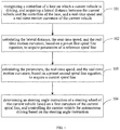
- Embodiments of a first aspect of the present disclosure provide a method for autonomously driving a vehicle, including: recognizing a centerline of a lane on which a current vehicle is driving; acquiring a lateral distance between the current vehicle and the centerline of the lane, and a real-time speed and a real-time motion curvature of the current vehicle; calculating the lateral distance, the real-time speed, and the real-time motion curvature, based on a preset first spiral line equation, to acquire parameters of a reference spiral line; calculating the parameters, the real-time speed, and the real-time motion curvature, based on a preset second spiral line equation, to acquire a current spiral line; and determining a steering angle instruction of a steering wheel based on a first curvature of the current spiral line; and driving the current vehicle based on the steering angle instruction.
- the method for autonomously driving the vehicle according to the embodiments of the present disclosure further has the following additional technical features.
- the method before determining the steering angle instruction of the steering wheel based on the first curvature of the current spiral line, the method includes: acquiring an included angle between the current vehicle and the centerline of the lane; acquiring a second curvature based on the included angle and the current spiral line; determining whether a difference between the first curvature and the second curvature is within a preset range; and in response to the difference being not within the preset range, correcting the first curvature based on a preset correction strategy.
- the method before controlling the angle of the steering wheel of the current vehicle based on the steering angle instruction to realize autonomous driving of the current vehicle, the method further includes: determining whether a yaw rate of the current vehicle is zero; and in response to the yaw rate being not zero, correcting the steering angle instruction based on the real-time motion curvature.
- Embodiments of a second aspect of the present disclosure provide an apparatus for autonomously driving a vehicle, including: a first acquisition module, configured to recognize a centerline of a lane on which a current vehicle is driving, and acquire a lateral distance between the current vehicle and the centerline of the lane, and a real-time speed and a real-time motion curvature of the current vehicle; a second acquisition module, configured to calculate the lateral distance, the real-time speed, and the real-time motion curvature, based on a preset first spiral line equation, to acquire parameters of a reference spiral line; a third acquisition module, configured to calculate the parameters, the real-time speed, and the real-time motion curvature, based on a preset second spiral line equation, to acquire a current spiral line; and a control module, configured to determine a steering angle instruction of a steering wheel of the current vehicle based on a first curvature of the current spiral line, and drive the current vehicle based on the steering angle instruction.
- a first acquisition module configured
- the apparatus for autonomously driving the vehicle according to the embodiments of the present disclosure further has the following additional technical features.
- the apparatus further includes: a fourth acquisition module, configured to acquire an included angle between the current vehicle and the centerline of the lane; a fifth acquisition module, configured to acquire a second curvature based on the included angle and the current spiral line; a first determination module, configured to determine whether a difference between the first curvature and the second curvature is within a preset range; and a first correction module, configured to, in response to the difference being not within the preset range, correct the first curvature based on a preset correction strategy.
- a fourth acquisition module configured to acquire an included angle between the current vehicle and the centerline of the lane
- a fifth acquisition module configured to acquire a second curvature based on the included angle and the current spiral line
- a first determination module configured to determine whether a difference between the first curvature and the second curvature is within a preset range
- a first correction module configured to, in response to the difference being not within the preset range, correct the first curvature based on a preset correction strategy.
- the apparatus further includes: a second determination module, configured to determine whether a yaw rate of the current vehicle is zero; and a second correction module, configured to, in response to the yaw rate being not zero, correct the steering angle instruction based on the real-time motion curvature.
- a second determination module configured to determine whether a yaw rate of the current vehicle is zero
- a second correction module configured to, in response to the yaw rate being not zero, correct the steering angle instruction based on the real-time motion curvature.
- Embodiments of a third aspect of the present disclosure provide a computer-readable storage medium having a computer program stored thereon.
- the computer program is executed by a processor, the method for autonomously driving the vehicle according to the embodiments of the first aspect is implemented.
- the present disclosure provides a new lateral motion control method for the autonomous driving system.
- a vehicle may smoothly realize lateral motions such as centerline following laterally, making a turn, and lane changing.
- the present disclosure which flexibly utilizes the principle of the spiral line, presents a clear physical relationship, and outputs continuous and satisfying curvature instructions, so that motion sensing of lateral autonomous driving may be greatly improved.
- instructions given by the present disclosure based on a spiral line relationship may greatly reduce the amount of computation, mitigate the dependence of an algorithm on a vehicle model, and achieve low cost and high universality.
- the present disclosure directly obtains spiral lines at other speeds and curvature variations with an eigen spiral line, thereby effectively simplifying calculation logic of the spiral lines, shortening system computation period, improving the efficiency of the control algorithm, reducing the occupation of system resources, mitigating reliance on a high-performance platform, and lowering the costs of mass production.
- FIG. 1 is a flowchart of a method for autonomously driving a vehicle according to an embodiment of the present disclosure. As shown in FIG. 1 , the method includes the following.
- a centerline of a lane on which a current vehicle is driving is recognized, and a lateral distance between the current vehicle and the centerline of the lane, and a real-time speed and a real-time motion curvature of the current vehicle, are acquired.
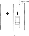
- the centerline of the lane is a centerline of a lane on which the vehicle is currently driving.
- the current vehicle is driving on lane A
- the centerline of lane A is the centerline of the lane.
- a picture of a lane where the current vehicle is driving may be obtained based on a vehicle-mounted camera or communication with the satellite.
- the center position of the lane in the picture of the lane is recognized as the position of the centerline of the lane based on an image recognition algorithm, for example, edge positions of the lane are recognized based on the image recognition algorithm, and then the centerline of the lane is determined based on edge positions on both sides of the lane.
- a spiral line between the current vehicle and the centerline of the lane is determined by using the centerline of the lane as a reference, so as to improve accuracy and motion sensing of vehicle control.
- the lateral distance between the current vehicle and the centerline of the lane may be obtained.
- the lateral distance may be a lateral distance between the center of the vehicle and the centerline of the lane.
- the real-time speed and real-time motion curvature of the current vehicle may be obtained based on the communication with CAN (Controller Area Network) and IMU (Inertial measurement unit) of the vehicle.
- CAN Controller Area Network
- IMU Inertial measurement unit
- a physical relationship between the spiral line and the previously-discovered lateral distance, the real-time speed and the real-time motion curvature of the current vehicle is acquired to obtain the current spiral of the current vehicle.
- the lateral distance, the real-time speed, and the real-time motion curvature are calculated based on a preset first spiral line equation to acquire parameters of a reference spiral line.
- the parameters, the real-time speed, and the real-time motion curvature are calculated based on a preset second spiral line equation to acquire a current spiral line.
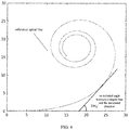
- reference spiral line equations are established in advance.
- parameters of the reference spiral line equation corresponding to the real-time parameters are determined, so as to determine the current spiral line corresponding to the current vehicle based on a physical corresponding relationship found between the real-time parameters such as real-time speed and the reference spiral line.
- the lateral distance, the real-time speed, and the real-time motion curvature are calculated based on the preset first spiral line equation to acquire the parameters of the reference spiral line.
- Cur R ( t ) is a reference curvature and A_Cur R is a curvature variation.
- a corresponding relationship between the distance and the included angle may be obtained, where the corresponding relationship may be represented by equations (5) and (6):
- X R t ⁇ 0 t V R ⁇ cos Yaw R t d t
- Y R t ⁇ 0 t V R ⁇ sin Yaw R t d t
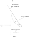
- a coordinate system is set on the reference lane line.
- the X axis is along the tangent direction of the reference lane line, and the forward direction is taken as positive.
- the Y axis is perpendicular to the tangent line, and the left direction is taken as positive.
- X R ( t ) is a distance of the reference spiral line in the horizontal direction
- Y R ( t ) is a distance of the reference spiral line in the vertical direction.
- the parameters, the real-time speed, and the real-time motion curvature are calculated based on the preset second spiral line equation to obtain the current spiral line, that is, the spiral line that matches real-time running parameters of the current vehicle may be determined based on a pre-established physical corresponding relationship.
- Curvatrue represents the current spiral line
- Cur R represents a curvature of the reference spiral line
- a _ Cur R represents a curvature variation that is obtained by deriving the curvature of the reference spiral line
- V R represents a reference speed
- V represents the real-time speed
- A_Cur represents the curvature variation that is obtained by deriving the real-time motion curvature.
- the current spiral line may be obtained based on the second spiral line equation.
- a steering angle instruction of a steering wheel is determined based on a first curvature of the current spiral line, and the current vehicle is controlled for autonomous driving based on the steering angle instruction.
- the steering angle instruction of the steering wheel is determined based on the first curvature of the current spiral line, and the current vehicle is controlled for autonomous driving based on the steering angle instruction. Consequently, the current vehicle moves along the real-time spiral line with the centerline of the lane, and may be smoothly controlled to realize lateral motions such as centerline following laterally, making a turn and lane changing.
- the included angle between the current vehicle and the centerline of the lane may be obtained.
- the included angle between the current vehicle and the centerline of the lane may be obtained based on image recognition, sensing of an infrared sensor, etc., and then the second curvature may be obtained based on the included angle and the current spiral line.
- the second curvature is a curvature of the vehicle while it is in motion. That is, the second curvature of the current spiral line is obtained with another parameter. It is determined whether a difference between the first curvature and the second curvature is within a preset range, such as whether the first curvature and the second curvature are equal. For example, as shown in FIG.
- the first curvature is CMD_Cur_base
- the second curvature is CMD_Cur_Corr
- CMD_Cur_Err is used to determine whether the current vehicle is moving according to the spiral line under the control of the instruction CMD_Cur_base. When CMD_Cur_Err is 0, it is determined that the current vehicle moves along the current spiral line.
- the first curvature is corrected based on a preset correction strategy. That is, it is considered that the curvature determined based on the real-time speed does not really follow the lane line, so that the first curvature is corrected, for example, a deviation is corrected based on an adjustable parameter K.
- the curvature obtained in the above embodiment is actually obtained based on an assumption that the current vehicle is parallel to the centerline of the lane and has no yaw rate. That is, before controlling a steering wheel angle of the current vehicle based on the steering angle instruction to realize autonomous driving of the current vehicle, it is determined whether the yaw rate of the current vehicle is zero, and in response to the yaw rate being not zero, the steering angle instruction is corrected based on the real-time motion curvature.
- the steering angle instruction of the steering wheel is obtained to control the vehicle, so as to control the vehicle to track the centerline of the lane.
- the present disclosure uses the spiral line equation obtained from a deviation of a yaw angle to correct the curvature instruction on the spiral line obtained from a lateral deviation, thereby effectively improving the lateral motion control accuracy of the vehicle and controlling the vehicle to strictly execute lateral motions based on a trajectory of the spiral line.
- autonomous driving control based on the spiral line may ensure motion sensing of autonomous driving.
- the spiral line corresponding to the driving of the current vehicle may be directly determined based on predetermined equations, that is, spiral lines at other speeds and curvature variations may be obtained directly with the reference spiral line, thereby effectively simplifying calculation logic of the spiral lines, shortening system computation period, improving the efficiency of the control algorithm, reducing the occupation of system resources, mitigating reliance on a high-performance platform, and lowering the costs of mass production, such that the control accuracy is guaranteed while the amount of computation is reduced.
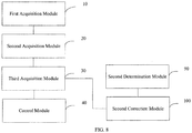
- FIG. 6 is a block diagram of an apparatus for autonomously driving a vehicle according to an embodiment of the present disclosure.
- the apparatus for autonomously driving a vehicle includes: a first acquisition module 10, a second acquisition module 20, a third acquisition module 30 and a control module 40.
- the first acquisition module 10 is configured to recognize a centerline of a lane on which a current vehicle is driving, and acquire a lateral distance between the current vehicle and the centerline of the lane, and a real-time speed and a real-time motion curvature of the current vehicle.
- the second acquisition module 20 is configured to calculate the lateral distance, the real-time speed, and the real-time motion curvature, based on a preset first spiral line equation, to acquire parameters of a reference spiral line.
- the third acquisition module 30 is configured to calculate the parameters, the real-time speed, and the real-time motion curvature, based on a preset second spiral line equation, to acquire a current spiral line.
- the control module 40 is configured to determine a steering angle instruction of a steering wheel of the current vehicle based on a first curvature of the current spiral line, and control the current vehicle for autonomous driving based on the steering angle instruction.
- the apparatus further includes: a fourth acquisition module 50, a fifth acquisition module 60, a first determination module 70, and a first correction module 80.
- the fourth acquisition module 50 is configured to acquire an included angle between the current vehicle and the centerline of the lane.
- the fifth acquisition module 60 is configured to acquire a second curvature based on the included angle and the current spiral line.
- the first determination module 70 is configured to determine whether a difference between the first curvature and the second curvature is within a preset range.
- the first correction module 80 is configured to, in response to the difference being not within the preset range, correct the first curvature based on a preset correction strategy.
- the apparatus further includes: a second determination module 90 and a second correction module 100.
- the second determination module 90 is configured to determine whether a yaw rate of the current vehicle is zero.
- the second correction module 100 is configured to, in response to the yaw rate being not zero, correct the steering angle instruction based on the real-time motion curvature.
- autonomous driving control based on the spiral line may ensure motion sensing of autonomous driving.
- the spiral line corresponding to the driving of the current vehicle may be directly determined based on predetermined equations, that is, spiral lines at other speeds and curvature variations may be obtained directly with the reference spiral line, thereby effectively simplifying calculation logic of the spiral lines, shortening system computation period, improving the efficiency of the control algorithm, reducing the occupation of system resources, mitigating reliance on a high-performance platform, and lowering the costs of mass production, such that the control accuracy is guaranteed while the amount of computation is reduced.
- the present disclosure further provides a computer device, including a processor and a storage device.
- the processor is configured to run, by reading an executable program code stored in the storage device, a program corresponding to the executable program code, so as to implement the method for autonomously driving the vehicle according to any of the above embodiments.
- the present disclosure further provides a computer-readable storage medium having a computer program stored thereon.
- the computer program is executed by a processor, the method for autonomously driving the vehicle according to any of the above embodiments is implemented.
- first and second are used herein for purposes of description and are not intended to indicate or imply relative importance or significance.
- the feature defined with “first” and “second” may comprise one or more this feature.
- a plurality of' means at least two, for example, two or three, unless specified otherwise.
- the logic and/or step described in other manners herein or shown in the flow chart, for example, a particular sequence table of executable instructions for realizing the logical function may be specifically achieved in any computer readable medium to be used by the instruction execution system, device or equipment (such as the system based on computers, the system comprising processors or other systems capable of obtaining the instruction from the instruction execution system, device and equipment and executing the instruction), or to be used in combination with the instruction execution system, device and equipment.
- the computer readable medium may be any device adaptive for including, storing, communicating, propagating or transferring programs to be used by or in combination with the instruction execution system, device or equipment.
- the computer readable medium comprise but are not limited to: an electronic connection (an electronic device) with one or more wires, a portable computer enclosure (a magnetic device), a random access memory (RAM), a read only memory (ROM), an erasable programmable read-only memory (EPROM or a flash memory), an optical fiber device and a portable compact disk read-only memory (CDROM).
- the computer readable medium may even be a paper or other appropriate medium capable of printing programs thereon, this is because, for example, the paper or other appropriate medium may be optically scanned and then edited, decrypted or processed with other appropriate methods when necessary to obtain the programs in an electric manner, and then the programs may be stored in the computer memories.
- each part of the present disclosure may be realized by the hardware, software, firmware or their combination.
- a plurality of steps or methods may be realized by the software or firmware stored in the memory and executed by the appropriate instruction execution system.
- the steps or methods may be realized by one or a combination of the following techniques known in the art: a discrete logic circuit having a logic gate circuit for realizing a logic function of a data signal, an application-specific integrated circuit having an appropriate combination logic gate circuit, a programmable gate array (PGA), a field programmable gate array (FPGA), etc.
- individual functional units in the embodiments of the present disclosure may be integrated in one processing module or may be separately physically present, or two or more units may be integrated in one module.
- the integrated module as described above may be achieved in the form of hardware, or may be achieved in the form of a software functional module. If the integrated module is achieved in the form of a software functional module and sold or used as a separate product, the integrated module may also be stored in a computer readable storage medium.
- the storage medium mentioned above may be read-only memories, magnetic disks or CD, etc.
Applications Claiming Priority (1)
| Application Number | Priority Date | Filing Date | Title |
|---|---|---|---|
| CN201910620964.9A CN110262509B (zh) | 2019-07-10 | 2019-07-10 | 车辆自动驾驶方法和装置 |
Publications (1)
| Publication Number | Publication Date |
|---|---|
| EP3763589A1 true EP3763589A1 (de) | 2021-01-13 |
Family
ID=67925559
Family Applications (1)
| Application Number | Title | Priority Date | Filing Date |
|---|---|---|---|
| EP20165984.4A Pending EP3763589A1 (de) | 2019-07-10 | 2020-03-26 | Verfahren, vorrichtungen und medien für autonom fahrende fahrzeuge |
Country Status (3)
| Country | Link |
|---|---|
| US (1) | US11338853B2 (de) |
| EP (1) | EP3763589A1 (de) |
| CN (1) | CN110262509B (de) |
Families Citing this family (10)
| Publication number | Priority date | Publication date | Assignee | Title |
|---|---|---|---|---|
| CN111123950B (zh) * | 2019-12-31 | 2023-08-29 | 东软睿驰汽车技术(沈阳)有限公司 | 行车控制方法、装置及车辆 |
| CN110967035B (zh) * | 2020-02-28 | 2020-09-04 | 杭州云动智能汽车技术有限公司 | 一种提高车载v2x车道匹配度方法 |
| CN113548038B (zh) * | 2020-04-22 | 2024-03-01 | 广州汽车集团股份有限公司 | 一种泊车曲率控制方法及系统、控制设备、存储介质 |
| CN112100565B (zh) * | 2020-08-31 | 2022-09-06 | 中国第一汽车股份有限公司 | 一种道路曲率确定方法、装置、设备及存储介质 |
| CN112124314B (zh) * | 2020-10-28 | 2021-09-03 | 重庆长安汽车股份有限公司 | 车辆自动变道横向路径规划方法、系统、车辆及存储介质 |
| CN113788020B (zh) * | 2021-09-17 | 2023-08-29 | 东风汽车集团股份有限公司 | 一种车辆的自适应巡航控制方法及装置 |
| CN114312837B (zh) * | 2021-12-28 | 2024-03-08 | 广州小鹏自动驾驶科技有限公司 | 变道路径规划方法、装置、车辆及存储介质 |
| CN115402336A (zh) * | 2022-09-01 | 2022-11-29 | 广州文远知行科技有限公司 | 方向轮转角计算方法、装置、设备及可读存储介质 |
| CN116110216B (zh) * | 2022-10-21 | 2024-04-12 | 中国第一汽车股份有限公司 | 车辆跨线时间确定方法、装置、存储介质及电子装置 |
| CN115861592B (zh) * | 2023-02-16 | 2023-05-26 | 之江实验室 | 基于神经网络的动作捕捉系统的速度精度优化方法及系统 |
Citations (3)
| Publication number | Priority date | Publication date | Assignee | Title |
|---|---|---|---|---|
| US20130006473A1 (en) * | 2009-12-04 | 2013-01-03 | Lutz Buerkle | Method and control unit for determining a cutting trajectory of a curve section of a roadway |
| US20130173115A1 (en) * | 2012-01-02 | 2013-07-04 | Ford Global Technologies, Llc | Lane-keeping assistance method for a motor vehicle |
| US20170364083A1 (en) * | 2016-06-21 | 2017-12-21 | Baidu Online Network Technology (Beijing) Co., Ltd. | Local trajectory planning method and apparatus for smart vehicles |
Family Cites Families (25)
| Publication number | Priority date | Publication date | Assignee | Title |
|---|---|---|---|---|
| US20090144030A1 (en) * | 2007-12-04 | 2009-06-04 | Tele Atlas North America, Inc. | Computer readable storage medium storing instructions for applying clothoid curve values to roadways in a geographic data information system |
| JP5279429B2 (ja) * | 2008-09-29 | 2013-09-04 | 株式会社アドヴィックス | 車両の速度制御装置 |
| US9090285B2 (en) * | 2008-12-05 | 2015-07-28 | Volkswagen Group Of America, Inc. | Method for providing a lanekeeping assistance based on modifying mechanical sources of steering torques |
| JP2011183995A (ja) * | 2010-03-10 | 2011-09-22 | Toyota Motor Corp | 車両制御装置 |
| US20120283913A1 (en) * | 2011-05-05 | 2012-11-08 | GM Global Technology Operations LLC | System and method for adjusting smoothness for lane centering steering control |
| US9168953B2 (en) * | 2011-11-08 | 2015-10-27 | Toyota Jidosha Kabushiki Kaisha | Vehicle travel track control device |
| CN102495631B (zh) * | 2011-12-09 | 2013-08-21 | 中国科学院合肥物质科学研究院 | 一种无人驾驶车辆跟踪预定轨迹的智能控制方法 |
| JP5783204B2 (ja) * | 2013-05-01 | 2015-09-24 | トヨタ自動車株式会社 | 運転支援装置および運転支援方法 |
| US9499197B2 (en) * | 2014-10-15 | 2016-11-22 | Hua-Chuang Automobile Information Technical Center Co., Ltd. | System and method for vehicle steering control |
| CN104615889B (zh) * | 2015-02-09 | 2017-12-26 | 武汉大学 | 基于回旋曲线追随的智能车辆路径跟踪方法及系统 |
| US9898932B2 (en) * | 2015-05-04 | 2018-02-20 | International Business Machines Corporation | Unmanned vehicle movement path assignment and management |
| DE102015223341A1 (de) * | 2015-11-25 | 2017-06-01 | Continental Automotive Gmbh | Lenkrad für ein Fahrzeug |
| US9974225B2 (en) * | 2016-01-14 | 2018-05-22 | Cnh Industrial America Llc | System and method for generating and implementing an end-of-row turn path |
| JP6455456B2 (ja) * | 2016-02-16 | 2019-01-23 | トヨタ自動車株式会社 | 車両制御装置 |
| US9849878B2 (en) * | 2016-02-26 | 2017-12-26 | GM Global Technology Operations LLC | System and method for providing a corrected lane following path through a curve for trailering vehicles |
| AU2017249204B2 (en) * | 2016-04-12 | 2022-03-31 | Agjunction Llc | Line acquisition path generation using curvature profiles |
| JP6852299B2 (ja) * | 2016-08-09 | 2021-03-31 | 株式会社デンソー | 運転支援システム |
| CN108459588B (zh) * | 2017-02-22 | 2020-09-11 | 腾讯科技(深圳)有限公司 | 自动驾驶方法及装置、车辆 |
| US10579062B2 (en) * | 2017-05-31 | 2020-03-03 | Baidu Usa Llc | Scalable smooth reference path generator for autonomous driving vehicles |
| JP7047659B2 (ja) * | 2017-08-15 | 2022-04-05 | 株式会社豊田自動織機 | 無人搬送車の制御装置及び制御方法 |
| WO2019037870A1 (en) * | 2017-08-25 | 2019-02-28 | Volvo Truck Corporation | METHOD FOR DIRECTING AN ARTICULATED VEHICLE |
| CN107618503B (zh) * | 2017-08-29 | 2019-07-23 | 广州小鹏汽车科技有限公司 | 一种自动泊车控制方法及系统 |
| CN107817790B (zh) * | 2017-09-05 | 2020-12-22 | 百度在线网络技术(北京)有限公司 | 一种计算车辆轨迹的曲率的方法和装置 |
| CN109733395B (zh) * | 2018-12-19 | 2020-06-09 | 江苏大学 | 一种基于可拓优度评价的自动驾驶汽车横向协调控制方法 |
| CN109835338B (zh) * | 2019-02-27 | 2020-11-06 | 北京海纳川汽车部件股份有限公司 | 转弯控制方法、装置及自动驾驶车辆 |
-
2019
- 2019-07-10 CN CN201910620964.9A patent/CN110262509B/zh active Active
-
2020
- 2020-03-26 EP EP20165984.4A patent/EP3763589A1/de active Pending
- 2020-06-23 US US16/909,610 patent/US11338853B2/en active Active
Patent Citations (3)
| Publication number | Priority date | Publication date | Assignee | Title |
|---|---|---|---|---|
| US20130006473A1 (en) * | 2009-12-04 | 2013-01-03 | Lutz Buerkle | Method and control unit for determining a cutting trajectory of a curve section of a roadway |
| US20130173115A1 (en) * | 2012-01-02 | 2013-07-04 | Ford Global Technologies, Llc | Lane-keeping assistance method for a motor vehicle |
| US20170364083A1 (en) * | 2016-06-21 | 2017-12-21 | Baidu Online Network Technology (Beijing) Co., Ltd. | Local trajectory planning method and apparatus for smart vehicles |
Also Published As
| Publication number | Publication date |
|---|---|
| US20210009203A1 (en) | 2021-01-14 |
| CN110262509A (zh) | 2019-09-20 |
| US11338853B2 (en) | 2022-05-24 |
| CN110262509B (zh) | 2022-06-28 |
Similar Documents
| Publication | Publication Date | Title |
|---|---|---|
| EP3763589A1 (de) | Verfahren, vorrichtungen und medien für autonom fahrende fahrzeuge | |
| CN109885066B (zh) | 一种运动轨迹预测方法及装置 | |
| CN110316193B (zh) | 预瞄距离的设置方法、装置、设备及计算机可读存储介质 | |
| JP2669031B2 (ja) | 自律走行車両 | |
| CN111923905A (zh) | 对轨迹进行估计的系统和方法 | |
| WO2022105393A1 (en) | Method, system, and device for controlling driving direction of vehicle | |
| CN111267857B (zh) | 一种自动驾驶车辆的变道轨迹生成方法及装置 | |
| US20100228420A1 (en) | Model based predictive control for automated lane centering/changing control systems | |
| EP1994455A2 (de) | Bahnverfolgungssteuersystem und -verfahren für mobile einheit | |
| US11024178B2 (en) | System and method for autonomously steering a vehicle | |
| CN112703539B (zh) | 行驶路径生成装置及车辆控制装置 | |
| CN111739342B (zh) | 用于避让侧前方车辆的方法、装置、介质以及车辆 | |
| CN115366876A (zh) | 自动驾驶车辆的横向控制方法、装置、车辆及存储介质 | |
| CN110789530A (zh) | 一种四轮独立转向-独立驱动车辆轨迹跟踪方法和系统 | |
| CN115123219A (zh) | 一种基于模糊pid的车道保持控制方法及装置 | |
| CN113525366A (zh) | 一种针对钢轮压路机液压横向控制器的横向控制方法 | |
| CN114740863A (zh) | 一种基于领航跟随的多机编队控制方法及装置 | |
| CN115542899A (zh) | 车辆路径跟踪的方法、装置、车辆、电子设备及介质 | |
| KR102509622B1 (ko) | 자동주차 시스템 안정성을 보장하는 근사 클로소이드 기반 로컬 경로 생성 방법 및 장치 | |
| CN112158196A (zh) | 自动泊车方法及装置 | |
| CN115675454B (zh) | 车辆碰撞识别方法、车载终端、车辆及存储介质 | |
| US20230409036A1 (en) | Apparatus for controlling driving of moving object and method thereof | |
| JP7430214B2 (ja) | 制御演算装置 | |
| JP7302693B1 (ja) | 運転制御装置、運転制御方法及びプログラム | |
| US11474246B2 (en) | Vehicle tracking device |
Legal Events
| Date | Code | Title | Description |
|---|---|---|---|
| PUAI | Public reference made under article 153(3) epc to a published international application that has entered the european phase |
Free format text: ORIGINAL CODE: 0009012 |
|
| STAA | Information on the status of an ep patent application or granted ep patent |
Free format text: STATUS: THE APPLICATION HAS BEEN PUBLISHED |
|
| AK | Designated contracting states |
Kind code of ref document: A1 Designated state(s): AL AT BE BG CH CY CZ DE DK EE ES FI FR GB GR HR HU IE IS IT LI LT LU LV MC MK MT NL NO PL PT RO RS SE SI SK SM TR |
|
| AX | Request for extension of the european patent |
Extension state: BA ME |
|
| STAA | Information on the status of an ep patent application or granted ep patent |
Free format text: STATUS: REQUEST FOR EXAMINATION WAS MADE |
|
| 17P | Request for examination filed |
Effective date: 20210415 |
|
| RBV | Designated contracting states (corrected) |
Designated state(s): AL AT BE BG CH CY CZ DE DK EE ES FI FR GB GR HR HU IE IS IT LI LT LU LV MC MK MT NL NO PL PT RO RS SE SI SK SM TR |
|
| RAP1 | Party data changed (applicant data changed or rights of an application transferred) |
Owner name: APOLLO INTELLIGENT DRIVING TECHNOLOGY (BEIJING) CO., LTD. |
|
| STAA | Information on the status of an ep patent application or granted ep patent |
Free format text: STATUS: EXAMINATION IS IN PROGRESS |
|
| 17Q | First examination report despatched |
Effective date: 20230302 |