EP3762589B1 - Verfahren zur herstellung eines hohlventils für verbrennungsmotoren - Google Patents
Verfahren zur herstellung eines hohlventils für verbrennungsmotoren Download PDFInfo
- Publication number
- EP3762589B1 EP3762589B1 EP19702880.6A EP19702880A EP3762589B1 EP 3762589 B1 EP3762589 B1 EP 3762589B1 EP 19702880 A EP19702880 A EP 19702880A EP 3762589 B1 EP3762589 B1 EP 3762589B1
- Authority
- EP
- European Patent Office
- Prior art keywords
- tubular wall
- flow forming
- valve
- finished product
- forming
- Prior art date
- Legal status (The legal status is an assumption and is not a legal conclusion. Google has not performed a legal analysis and makes no representation as to the accuracy of the status listed.)
- Active
Links
Images
Classifications
-
- B—PERFORMING OPERATIONS; TRANSPORTING
- B21—MECHANICAL METAL-WORKING WITHOUT ESSENTIALLY REMOVING MATERIAL; PUNCHING METAL
- B21D—WORKING OR PROCESSING OF SHEET METAL OR METAL TUBES, RODS OR PROFILES WITHOUT ESSENTIALLY REMOVING MATERIAL; PUNCHING METAL
- B21D22/00—Shaping without cutting, by stamping, spinning, or deep-drawing
- B21D22/14—Spinning
- B21D22/16—Spinning over shaping mandrels or formers
-
- B—PERFORMING OPERATIONS; TRANSPORTING
- B21—MECHANICAL METAL-WORKING WITHOUT ESSENTIALLY REMOVING MATERIAL; PUNCHING METAL
- B21K—MAKING FORGED OR PRESSED METAL PRODUCTS, e.g. HORSE-SHOES, RIVETS, BOLTS OR WHEELS
- B21K1/00—Making machine elements
- B21K1/20—Making machine elements valve parts
- B21K1/22—Making machine elements valve parts poppet valves, e.g. for internal-combustion engines
-
- F—MECHANICAL ENGINEERING; LIGHTING; HEATING; WEAPONS; BLASTING
- F01—MACHINES OR ENGINES IN GENERAL; ENGINE PLANTS IN GENERAL; STEAM ENGINES
- F01L—CYCLICALLY OPERATING VALVES FOR MACHINES OR ENGINES
- F01L2303/00—Manufacturing of components used in valve arrangements
-
- F—MECHANICAL ENGINEERING; LIGHTING; HEATING; WEAPONS; BLASTING
- F01—MACHINES OR ENGINES IN GENERAL; ENGINE PLANTS IN GENERAL; STEAM ENGINES
- F01L—CYCLICALLY OPERATING VALVES FOR MACHINES OR ENGINES
- F01L3/00—Lift-valve, i.e. cut-off apparatus with closure members having at least a component of their opening and closing motion perpendicular to the closing faces; Parts or accessories thereof
- F01L3/12—Cooling of valves
- F01L3/14—Cooling of valves by means of a liquid or solid coolant, e.g. sodium, in a closed chamber in a valve
-
- F—MECHANICAL ENGINEERING; LIGHTING; HEATING; WEAPONS; BLASTING
- F01—MACHINES OR ENGINES IN GENERAL; ENGINE PLANTS IN GENERAL; STEAM ENGINES
- F01L—CYCLICALLY OPERATING VALVES FOR MACHINES OR ENGINES
- F01L3/00—Lift-valve, i.e. cut-off apparatus with closure members having at least a component of their opening and closing motion perpendicular to the closing faces; Parts or accessories thereof
- F01L3/20—Shapes or constructions of valve members, not provided for in preceding subgroups of this group
-
- F—MECHANICAL ENGINEERING; LIGHTING; HEATING; WEAPONS; BLASTING
- F16—ENGINEERING ELEMENTS AND UNITS; GENERAL MEASURES FOR PRODUCING AND MAINTAINING EFFECTIVE FUNCTIONING OF MACHINES OR INSTALLATIONS; THERMAL INSULATION IN GENERAL
- F16K—VALVES; TAPS; COCKS; ACTUATING-FLOATS; DEVICES FOR VENTING OR AERATING
- F16K1/00—Lift valves or globe valves, i.e. cut-off apparatus with closure members having at least a component of their opening and closing motion perpendicular to the closing faces
- F16K1/32—Details
- F16K1/34—Cutting-off parts, e.g. valve members, seats
- F16K1/36—Valve members
-
- F—MECHANICAL ENGINEERING; LIGHTING; HEATING; WEAPONS; BLASTING
- F16—ENGINEERING ELEMENTS AND UNITS; GENERAL MEASURES FOR PRODUCING AND MAINTAINING EFFECTIVE FUNCTIONING OF MACHINES OR INSTALLATIONS; THERMAL INSULATION IN GENERAL
- F16K—VALVES; TAPS; COCKS; ACTUATING-FLOATS; DEVICES FOR VENTING OR AERATING
- F16K49/00—Means in or on valves for heating or cooling
- F16K49/005—Circulation means for a separate heat transfer fluid
- F16K49/007—Circulation means for a separate heat transfer fluid located within the obturating element
Definitions
- the present invention relates to a method for producing hollow valves, or cavity valves, for internal combustion engines and hollow valves produced thereby.
- Intake and exhaust valves in combustion engines are components subject to high thermal and mechanical stress. Adequate cooling is therefore necessary to ensure long-term functionality of the valves.
- Hollow disc valves have advantages over solid-stem valves and hollow-stem valves (i.e., a hollow valve with a cavity only in the stem) because a cavity is present in both the stem and the valve head, allowing for improved internal cooling using a cooling medium, e.g., sodium.
- Other advantages include lower weight, the avoidance of hot spots, and a reduction in CO2 emissions.
- Hollow valves are usually manufactured using a combination of different processes, such as forging, turning, and welding. Turning or milling the cavity is particularly cost-intensive. Weld spots on the plate surface or other critical operational points should also be avoided.
- Another disadvantage of conventional processes is that a large number of process steps are often necessary.
- EP 0898055 A1 a hollow disc valve, which is manufactured by closing a hollow blank by welding.
- DE 102015220891 A1 It is known to produce an internally cooled valve by forming a cup-shaped preform using rolling. Further relevant prior art can be found in EP 2 690 262 A1 and EP 0 151 976 A .
- the object of the present invention is therefore to provide a manufacturing method for hollow valves or for a valve body for hollow valves, which does not have the disadvantages mentioned and at the same time has high productivity and good material utilization.
- the problem is solved by a method for producing a valve body of a hollow valve according to the features of the appended claim 1.
- the method for manufacturing a valve body of a hollow valve comprises the steps of providing a preform having a valve head and a tubular wall surrounding a cylindrical cavity, and flow forming the tubular wall over a flow forming mandrel inserted into the cavity to increase a length of the tubular wall.
- providing the preform may comprise: providing a cup-shaped semi-finished product, the semi-finished product having the tubular wall surrounding the cylindrical cavity of the semi-finished product and a bottom portion; and forming the valve head from the bottom portion.
- providing the cup-shaped semi-finished product may comprise: providing an at least partially cylindrical blank; and forming the cup-shaped semi-finished product from the blank.
- the forming of the cup-shaped semi-finished product can be carried out by extrusion or forging.
- valve head can be formed by extrusion or forging.
- spinning rollers are used in the spinning process, Preferably three pressing rollers are used.
- the plurality of spinning rollers are radially and axially offset from one another during the spinning process.
- the method may further comprise: further flow forming the tubular wall without a flow forming mandrel.
- the method may further comprise: reducing an outer diameter of the tubular wall after the flow forming.
- the reduction of the outer diameter of the tubular wall can be carried out by swaging or drawing in.
- the reduction of the outer diameter of the tubular wall can be carried out without a mandrel.
- the reduction of the outer diameter of the tubular wall can be carried out with a mandrel inserted into the cavity.
- the method may further comprise: filling a cooling medium, in particular sodium, into the cavity; and closing the cavity.
- a cooling medium in particular sodium
- a hollow valve comprising a valve body manufactured using the above method.
- a blank 2 made of a valve steel known to those skilled in the art has an at least partially cylindrical shape, preferably a circular cylindrical shape, corresponding to the circular shape of the valve body or valve to be produced.
- the blank 2 is placed in a Fig. 1B
- the cup-shaped semi-finished product (or workpiece) 4 shown is formed.
- the semi-finished product 4 in the form of a cup comprises a base section 10, from which a valve head (or valve disk) 12 is later formed, and a tubular wall (or annular wall) 14, which surrounds a cylindrical, preferably circular-cylindrical, cavity 8 of the cup-shaped semi-finished product 4 and from which a valve stem 20 is later formed.
- material may possibly flow between the base section 10 and the tubular wall 14. More generally, according to the invention, the cup-shaped semi-finished product 4 is provided directly; the method then starts with the provision of the Fig. 1B shown cup-shaped semi-finished product 4.
- valve head 12 is formed from the base section 10.
- a preform 6 of the valve body thus obtained is Fig. 1C shown.
- Both the forming of the blank 2 into a cup-shaped workpiece 4 and the forming of the valve head 12 from the base section 10 can be carried out, for example, by a hot or cold forming process.
- extrusion or forging is used.
- a punch is pressed into the blank 2 or the semi-finished product 4 to form the cavity 8 or the valve head 12, i.e., it essentially involves (cup) backward extrusion or transverse extrusion.
- the preform 6 can also be formed directly from the blank 2 in a single forming step, e.g., forging or extrusion.
- an axial length of the tubular wall 14 is increased.
- 'Axial' here refers to the direction defined by the tubular wall 14 (i.e., the future shaft), i.e., to the (center) axis of the tubular wall;
- 'radial' is a direction orthogonal to the axial direction. A length of the tubular wall 6 is therefore measured in the axial direction.
- flow-forming or cylindrical flow-forming is carried out over a flow-forming mandrel 22; cf. Fig. 2
- the preform rotates and at least one flow forming roller 24, 26, which rotates due to frictional engagement, is pressed against the outside of the tubular wall and moved in the axial direction, resulting in a plastic deformation.
- the resulting incremental forming leads to advantageous work hardening of the machined steel.
- the wall thickness of the tubular wall decreases while at the same time the axial length of the tubular wall increases.
- the at least one flow forming roller is moved several times in the axial direction if necessary until the desired increase in length or reduction in wall thickness is achieved.
- the radial distance of the at least one flow forming roller from the axis of the tubular wall is successively reduced in successive passes.
- flow-forming essentially results in an elongation of the tubular wall 14, with its outer diameter decreasing slightly (corresponding to the reduction in wall thickness). If a greater reduction in the outer diameter is desired, flow-forming can also be performed with multiple flow-forming rollers without a flow-forming mandrel.
- a valve body 16 for a hollow stem valve can be obtained in this way (cf. Fig. 1D , it being noted that the relative dimensions shown in the figures do not necessarily correspond to the actual relative dimensions, in particular Fig. 1D the diameter of the valve disc/head in relation to the stem diameter is shown smaller than in a typical actual valve, and the stem diameter in relation to the length of the stem 20 is also shown larger than usual).
- the outer diameter of the tubular wall 14 is reduced in order to obtain a finished valve body 18 for a hollow disc valve, the valve stem 20 of which has a predetermined outer diameter, ie a desired target diameter; cf. Fig. 1F
- This forming step is preferably carried out without a mandrel inserted so that the diameter can be effectively reduced.
- This step leads, in addition to a reduction in the outer diameter, to a further elongation of the tubular wall 14 and, if carried out without a mandrel, to an increase in the wall thickness of the tubular wall 14.
- the wall thickness would therefore have to be set somewhat smaller in the preceding flow-forming step if necessary in order to obtain a specific wall thickness, and thus a specific inner diameter for a given outer diameter D, taking into account the increase in thickness in the final step.
- the outer diameter of the tubular wall 14 can be reduced by swaging or necking, with swaging being preferred.
- swaging it is important that no further forming step of the valve body 18 for a hollow disc valve takes place after swaging to reduce the outer diameter of the tubular wall 14, as this would impair the positive material properties obtained by swaging. Therefore, swaging is the final forming step in this case.
- Rotary swaging is an incremental pressure forming process in which the workpiece to be machined is hammered radially from different sides in rapid succession. The resulting pressure causes the material to "flow," so to speak, and the material structure is not distorted by tensile stresses.
- Rotary swaging is preferably carried out as a cold forming process, i.e., below the recrystallization temperature of the material being machined.
- the key advantage of using rotary swaging as the final forming step is that compressive stresses are induced by the radial force application during rotary swaging, thereby preventing the occurrence of tensile stresses that increase the susceptibility to cracking; this is particularly true for the surface layers of the hollow shaft.
- Rotary swaging thus interacts advantageously with the preceding, also incremental forming process of flow-forming, so that optimal material properties, e.g., strength, are achieved.
- a cooling medium e.g. sodium
- a valve stem end piece which is attached, for example, by means of friction welding or another welding process (not shown in the figures).
- the reduction of the outer diameter can be carried out in several sub-steps (an intermediate step is, for example, in Fig. 1E shown), whereby the individual sub-steps can be carried out either with or without a mandrel (at the beginning of a sub-step, the diameter of a mandrel can be smaller than the diameter of the cavity); the diameter of the mandrels of successive sub-steps can also be reduced.
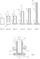
- Fig. 2 represents the process step of flow forming, which takes place between Fig. 1C and Fig. 1D takes place, in a sectional view.
- a flow-forming mandrel 22 is inserted into the cavity of the preform 6.
- the flow-forming mandrel rotates together with the preform 6 and a tailstock 28, which supports the preform on the valve base.
- Two opposing flow-forming rollers 24, 26, which also rotate by friction, are pressed against the tubular wall 14.
- the flow-forming rollers 24, 26 are moved relative to the preform in the axial direction, resulting in plastic deformation of the tubular wall 14, whereby the outer radius of the tubular wall 14 decreases and, at the same time, the length of the tubular wall 14 increases (in the axial direction).
- the material of the tubular wall 14 "flows" in the direction of movement of the flow-forming rollers 24, 26 (synchronized flow-forming rollers).
- the directions of rotation of the preform (together with the flow-forming mandrel and tailstock) and the flow rolls, the direction of movement of the flow rolls 24, 26 and the flow direction of the material of the tubular wall 14 are indicated by arrows in the figure.
- Two spinning rollers 24, 26 are shown (partially) as an example, as is the The use of more than two spinning rollers is possible, although the use of two or three spinning rollers is preferred.
- the plurality of spinning rollers are preferably distributed evenly around the circumference; i.e., with two spinning rollers, the angle (in the circumferential direction) between the spinning rollers is approximately 180°, with three spinning rollers, approximately 120°, etc. This ensures that the preform is supported in all directions.
- Radial offset means that the radial distance of the spinning rollers 24, 26 from the center axis is different.
- the axial offset is achieved by moving the spinning rollers 24, 26 at different times, whereby (obviously) the sequence is such that the spinning roller with the greatest radial distance from the center axis is moved first, followed by the one with the second greatest radial distance, and so on. In this way, the process can be accelerated, since several radius or wall thickness reduction steps can be carried out in a single pass.
- spinning rollers with different diameters can also be used.
Landscapes
- Engineering & Computer Science (AREA)
- Mechanical Engineering (AREA)
- Chemical & Material Sciences (AREA)
- Combustion & Propulsion (AREA)
- General Engineering & Computer Science (AREA)
- Forging (AREA)
- Shaping Metal By Deep-Drawing, Or The Like (AREA)
Description
- Die vorliegende Erfindung betrifft ein Verfahren zur Herstellung von Hohlventilen, bzw. Hohlraumventilen, für Verbrennungsmotoren und damit hergestellte Hohlventile.
- Ein- und Auslassventile sind bei Verbrennungsmotoren thermisch und mechanisch hoch beanspruchte Bauteile. Eine ausreichende Kühlung ist daher notwendig, um eine dauerhafte Funktionsfähigkeit der Ventile sicherzustellen. Hierbei sind Hohltellerventile gegenüber Vollschaftventilen und Hohlschaftventilen (d.h. ein Hohlventil bei dem lediglich im Schaft ein Hohlraum vorgesehen ist) vorteilhaft, da ein Hohlraum sowohl im Schaft als auch im Ventilkopf vorhanden ist, wodurch eine verbesserte interne Kühlung - mittels eines Kühlmediums, z.B. Natrium - erzielt werden kann. Weitere Vorteile sind ein geringeres Gewicht, die Vermeidung von Hot-Spots und eine CO2-Reduzierung.
- Hergestellt werden Hohlventile üblicherweise durch eine Kombination verschiedener Verfahren, wie z.B. Schmieden, Drehen und Schweißen. Hierbei ist insbesondere das Drehen oder Fräsen des Hohlraumes kostenintensiv. Auch sollten Schweißpunkte an der Tellerfläche oder an anderen betriebsbedingt kritischen Stellen vermieden werden. Ein weiterer Nachteil bekannter Verfahren ist, dass oftmals eine große Anzahl von Prozessschritten notwendig ist. Beispielsweise betrifft die
EP 0898055 A1 ein Hohltellerventil, das durch Schließen eines hohlen Rohlings mittels Schweißens hergestellt wird. Außerdem ist aus derDE 102015220891 A1 bekannt, ein innengekühltes Ventil durch Umformen einer becherförmigen Vorform mittels Walzen herzustellen. Weiterer relevanter Stand der Technik findet sich inEP 2 690 262 A1 undEP 0 151 976 A . - Aufgabe der vorliegenden Erfindung ist es also ein Herstellungsverfahren für Hohlventile bzw. für einen Ventilkörper für Hohlventile bereitzustellen, welches die genannten Nachteile nicht aufweist und gleichzeitig eine hohe Produktivität und gute Materialausnutzung aufweist.
- Erfindungsgemäß wird das Problem gelöst durch ein Verfahren zur Herstellung eines Ventilkörpers eines Hohlventils gemäß den Merkmalen des angehängten Anspruchs 1.
- Das Verfahren zur Herstellung eines Ventilkörpers eines Hohlventils umfasst die Schritte von Bereitstellen einer Vorform mit einem Ventilkopf und einer rohrförmigen Wand, die einen zylindrischen Hohlraum umgibt, und Drückwalzen der rohrförmigen Wand über einem Drückwalzdorn, der in den Hohlraum eingesetzt ist, um eine Länge der rohrförmigen Wand zu vergrößern.
- Gemäß einem Aspekt der vorliegenden Erfindung kann das Bereitstellen der Vorform umfassen: Bereitstellen eines napfförmigen Halbzeugs, wobei das Halbzeug die rohrförmige Wand, die den zylindrischen Hohlraum des Halbzeugs umgibt, und einen Bodenabschnitt aufweist; und Formen des Ventilkopfes aus dem Bodenabschnitt.
- Gemäß einem weiteren Aspekt kann das Bereitstellen des napfförmigen Halbzeugs umfassen: Bereitstellen eines zumindest teilweise zylindrischen Rohlings; und Formen des napfförmigen Halbzeugs aus dem Rohling.
- Gemäß einem weiteren Aspekt kann das Formen des napfförmigen Halbzeugs durch Fließpressen oder Schmieden erfolgen.
- Gemäß einem weiteren Aspekt kann das Formen des Ventilkopfes durch Fließpressen oder Schmieden erfolgen.
- Erfindungsgemäß werden beim Drückwalzen mehrere Drückwalzen verwendet, wobei bevorzugt drei Drückwalzen verwendet werden.
- Erfindungsgemäß sind die mehreren Drückwalzen während des Drückwalzens zueinander radial und axial versetzt.
- Gemäß einem weiteren Aspekt kann das Verfahren weiterhin umfassen: ein weiteres Drückwalzen der rohrförmigen Wand ohne Drückwalzdorn.
- Gemäß einem weiteren Aspekt kann das Verfahren weiterhin umfassen: Reduzieren eines Außendurchmessers der rohrförmigen Wand nach dem Drückwalzen.
- Gemäß einem weiteren Aspekt kann das Reduzieren des Außendurchmessers der rohrförmigen Wand durch Rundkneten oder Einziehen erfolgen.
- Gemäß einem weiteren Aspekt kann das Reduzieren des Außendurchmessers der rohrförmigen Wand ohne Dorn erfolgen.
- Gemäß einem weiteren Aspekt kann das Reduzieren des Außendurchmessers der rohrförmigen Wand mit einem in den Hohlraum eingesetzten Dorn erfolgen.
- Gemäß einem weiteren Aspekt kann das Verfahren weiterhin umfassen: Einfüllen eines Kühlmediums, insbesondere Natrium, in den Hohlraum; und Schließen des Hohlraums.
- Das Problem wird weiterhin gelöst durch Hohlventil, welches einen Ventilkörper umfasst, der unter Verwendung des vorstehenden Verfahrens hergestellt wurde.
- Im Folgenden werden beispielhafte Ausführungsformen der Erfindung unter Bezug auf die Figuren genauer beschrieben, wobei
-
Figuren 1A - 1F verschiedene Zwischenschritte der erfindungsgemäßen Herstellung eines Ventilkörpers eines Hohlventils (dargestellt inFig. 1D bzw.Fig. 1F ) aus einem Rohling (dargestellt inFig. 1A ) zeigen; und -
Fig. 2 eine Schnittansicht während des Drückwalzens zeigt. - Im Folgenden werden sowohl in der Beschreibung als auch in der Zeichnung gleiche Bezugszeichen für gleiche oder ähnliche Elemente oder Komponenten verwendet. Es ist zudem eine Bezugszeichenliste angegeben, die für alle Figuren gültig ist. Die in den Figuren dargestellten Ausführungen sind lediglich schematisch und stellen nicht notwendigerweise die tatsächlichen Größenverhältnisse dar.
- In den
Figuren 1A bis 1F sind, in Schnittansichten, verschiedene Zwischenstufen des erfindungsgemäßen Herstellungsverfahrens dargestellt, wobei auch optionale bzw. bevorzugte Herstellungsschritte/Zwischenstufen dargestellt sind. - Bevorzugt dient als Ausgangspunkt, siehe
Fig. 1A , ein Rohling 2 aus einem dem Fachmann bekannten Ventilstahl. Der Rohling weist eine zumindest teilweise zylindrische Form auf, bevorzugt eine kreiszylindrische Form, entsprechend der Kreisform des herzustellenden Ventilkörpers bzw. Ventils. - Der Rohling 2 wird in ein in
Fig. 1B dargestelltes napfförmiges Halbzeug (bzw. Werkstück ) 4 umgeformt. Das Halbzeug 4 in Form eines Napfes umfasst einen Bodenabschnitt 10, aus dem später ein Ventilkopf (bzw. Ventilteller) 12 gebildet wird, und eine rohrförmige Wand (bzw. ringförmige Wand) 14, die einen zylindrischen, bevorzugt kreiszylindrischen, Hohlraum 8 des napfförmigen Halbzeugs 4 umgibt und aus der später ein Ventilschaft 20 gebildet wird. Hierbei kann während der nachfolgenden Umformschritte eventuell Material zwischen Bodenabschnitt 10 und rohrförmiger Wand 14 fließen. Allgemeiner wird erfindungsgemäß das napfförmige Halbzeug 4 direkt bereitgestellt; das Verfahren startet dann also mit Bereitstellen des inFig. 1B dargestellten napfförmigen Halbzeugs 4. - In einem anschließenden Umformschritt wird aus dem Bodenabschnitt 10 der Ventilkopf 12 geformt. Eine dadurch erhaltene Vorform 6 des Ventilkörpers ist in
Fig. 1C dargestellt. - Sowohl das Umformen des Rohlings 2 in ein napfförmiges Werkstück 4 als auch das Formen des Ventilkopfs 12 aus dem Bodenabschnitt 10 kann z.B. durch ein Warm- oder Kaltumformverfahren durchgeführt werden. Bevorzugt wird Fließpressen oder Schmieden verwendet. Beim Fließpressen wird ein Stempel in den Rohling 2 bzw. das Halbzeug 4 gepresst, um den Hohlraum 8 bzw. den Ventilkopf 12 zu formen, d.h. es handelt sich im Wesentlichen um (Napf-)Rückwärtspressfließen bzw. Querfließpressen. Die Vorform 6 kann auch in einem einzigen Umformschritt, z.B. Schmieden oder Fließpressen, direkt aus dem Rohling 2 geformt werden.
- Im nächsten Bearbeitungsschritt, von
Fig. 1C nachFig. 1D , wird eine axiale Länge der rohrförmigen Wand 14 vergrößert. ,Axial' bezieht sich hier auf die durch die rohrförmige Wand 14 (d.h. den späteren Schaft) definierte Richtung, also auf die (Mittel-)Achse der rohrförmigen Wand; ,radial' ist entsprechend eine Richtung orthogonal zur axialen Richtung. Eine Länge der rohrförmigen Wand 6 wird also in axialer Richtung gemessen. - Hierzu wird erfindungsgemäß Drückwalzen bzw. Zylinderdrückwalzen über einem Drückwalzdorn 22 durchgeführt; vgl.
Fig. 2 . Beim Drückwalzen rotiert die Vorform und es wird mindestens eine, durch Reibschluss mitrotierende, Drückwalze 24, 26 gegen die Außenseite der rohrförmigen Wand gedrückt und in axialer Richtung bewegt, so dass es zu einer plastischen Formänderung kommt. Die damit einhergehende inkrementelle Umformung führt zu einer vorteilhaften Kaltverfestigung des bearbeiteten Stahls. Insgesamt verringert sich die Wanddicke der rohrförmigen Wand während sich gleichzeitig die axiale Länge der rohrförmigen Wand vergrößert. Die mindestens eine Drückwalze wird gegebenenfalls mehrmals in axialer Richtung verfahren bis die gewünschte Längenzunahme bzw. Wanddickenverringerung erreicht ist. Dabei wird der radiale Abstand der mindestens einen Drückwalze von der Achse der rohrförmigen Wand bei aufeinanderfolgenden Durchgängen sukzessive verringert. - Das Drückwalzen führt also, aufgrund des eingesetzten Drückwalzdorns, im Wesentlichen zu einer Längung der rohrförmigen Wand 14, wobei deren Außendurchmesser ein wenig abnimmt (entsprechend der Abnahme der Wanddicke). Falls eine größere Abnahme des Außendurchmessers erwünscht ist, kann auch ein Drückwalzen, mit mehreren Drückwalzen, ohne Drückwalzdorn erfolgen.
- Falls Abmessungen der Vorform 6 und Parameter des Drückwalzens so gewählt sind, dass die durch das Drückwalzen erreichte Länge der rohrförmigen Wand 14, der durch das Drückwalzen erreichte Außendurchmesser und ein Innendurchmesser der rohrförmigen Wand 14 der Vorform (der einem Durchmesser des Drückwalzdorns entspricht) den gewünschten Abmessungen des herzustellenden Hohlventils entsprechen, kann auf diese Weise ein Ventilkörper 16 für ein Hohlschaftventil erhalten werden (vgl.
Fig. 1D , wobei angemerkt sei, dass die in den Figuren gezeigten relativen Abmessungen nicht den tatsächlichen relativen Abmessungen entsprechen müssen, insbesondere ist inFig. 1D der Durchmesser des Ventiltellers/-kopfes im Verhältnis zum Schaftdurchmesser kleiner als bei einem üblichen tatsächlichen Ventil dargestellt, ebenso ist der Schaftdurchmesser im Verhältnis zur Länge des Schaftes 20 größer als üblich dargestellt). - Abschließend (von
Fig. 1D überFig. 1E nachFig. 1F ) wird, optional, der Außendurchmesser der rohrförmigen Wand 14 reduziert, um einen fertiggestellten Ventilkörper 18 für ein Hohltellerventil zu erhalten, dessen Ventilschaft 20 einen vorbestimmten Außendurchmesser aufweist, d.h. einen gewünschten Zieldurchmesser aufweist; vgl.Fig. 1F . Dieser Umformschritt erfolgt bevorzugt ohne eingesetzten Dorn, damit der Durchmesser effektiv verkleinert werden kann. Dieser Schritt führt, neben einer Verringerung des Außendurchmessers, auch zu einer weiteren Längung der rohrförmigen Wand 14 und, falls ohne Dorn durchgeführt, zu einer Zunahme der Wanddicke der rohrförmigen Wand 14. Die Wanddicke wäre also gegebenenfalls im vorhergehenden Drückwalzschritt etwas kleiner einzustellen, um unter Berücksichtigung der Dickenzunahme im abschließenden Schritt eine bestimmte Wanddicke, und damit bei gegebenen Außeridurchmesser D einen bestimmten Innendurchmesser, zu erhalten. - Das Reduzieren des Außendurchmessers der rohrförmigen Wand 14 kann durch Rundkneten oder Einziehen ("Necking", Durchmesserverminderung durch Einschnüren) erfolgen, wobei Rundkneten bevorzugt wird. Beim Rundkneten ist wichtig, dass nach dem Rundkneten zur Reduzierung des Außendurchmessers der rohrförmigen Wand 14 kein weiterer Umformschritt des Ventilkörpers 18 für ein Hohltellerventil stattfindet, da dies die durch das Rundkneten erhaltenen positiven Materialeigenschaften verschlechtern würde. Rundkneten ist also in diesem Fall der abschließende Umformschritt.
- Beim Rundkneten handelt es sich um ein inkrementelles Druckumformverfahren, bei dem in schneller Abfolge von verschiedenen Seiten in radialer Richtung auf das zu bearbeitende Werkstück eingehämmert wird. Durch den dadurch entstehenden Druck ,fließt' das Material sozusagen und die Materialstruktur wird nicht durch Zugspannungen verzerrt. Bevorzugt wird Rundkneten als Kaltumformverfahren, d.h. unterhalb der Rekristallisationstemperatur des bearbeiteten Materials, ausgeführt. Wesentlicher Vorteil der Verwendung von Rundkneten als abschließenden Umformschritt ist also, dass beim Rundkneten durch die radiale Krafteinleitung Druckspannungen induziert werden, wodurch das Auftreten von Zugspannungen, welche die Anfälligkeit für Risse erhöhen verhindert wird, insbesondere trifft dies für die Randschichten des Hohlschaftes zu. Das Rundkneten wirkt somit mit dem vorhergehenden, ebenfalls inkrementellen Umformverfahren des Drückwalzens auf vorteilhafte Weise zusammen, so dass optimale Materialeigenschaften, z.B. Festigkeit, erreicht werden.
- Weitere Vorteile des Rundknetens als abschließenden Umformschritt - gegenüber Ziehverfahren oder "Necking" (Einziehen) - sind durch eine bessere erreichbare Oberflächenqualität und durch eine relativ höhere Durchmesserreduzierung des Schaftes je Schritt gegeben. Aufgrund der hohen erreichbaren Oberflächenqualität und dadurch, dass die einhaltbaren Toleranzen beim Rundkneten sehr klein sind, ist eine Nachbearbeitung des Ventilschaftes meist nicht notwendig. Mit Freiformverfahren bzw. Stauchverfahren - wie z.B. Necking - lässt sich im Allgemeinen nur eine schlechtere Oberflächenqualität bzw. Toleranzeinhaltung erreichen. Dementsprechend sollte nach dem Rundkneten zur Reduzierung des Außendurchmessers der rohrförmigen Wand insbesondere kein weiterer Verfahrensschritt mittels eines Ziehverfahrens oder Neckings erfolgen.
- Um den Herstellungsprozess des Hohlventils abzuschließen kann weiterhin ein Kühlmedium, z.B. Natrium, über das nach außen offene Ende des Ventilschaftes in den Hohlraum des Ventilkörpers eingefüllt werden und anschließend dieses Ende des Ventilschaftes verschlossen werden, z.B. durch ein Ventilschaftendstück, welches, etwa mittels Reibschweißen oder einem anderen Schweißverfahren, angebracht wird (in den Figuren nicht dargestellt).
- Das Reduzieren des Außendurchmessers kann in mehreren Teilschritten erfolgen (ein Zwischenschritt ist beispielsweise in
Fig. 1E dargestellt), wobei die einzelnen Teilschritte jeweils wahlweise mit oder ohne Dorn erfolgen können (zu Beginn eines Teilschritts kann der Durchmesser eines Dorns kleiner als der Durchmesser des Hohlraums sein); auch kann ein Durchmesser der Dorne aufeinanderfolgender Teilschritte verringert werden. -
Fig. 2 stellt den Verfahrensschritt des Drückwalzens, das zwischenFig. 1C und Fig. 1D stattfindet, in einer Schnittdarstellung dar. Hierbei wird in den Hohlraum der Vorform 6 ein Drückwalzdorn 22 eingesetzt. Der Drückwalzdorn rotiert zusammen mit der Vorform 6 und einem Reitstock 28, der die Vorform am Ventilboden abstützt. Gegen die rohrförmige Wand 14 werden zwei einander gegenüberliegende Drückwalzen 24, 26 gedrückt, die mittels Reibschluss ebenfalls rotieren. Die Drückwalzen 24, 26 werden relativ zur Vorform in axialer Richtung bewegt, dadurch kommt es zu einer plastischen Verformung der rohrförmigen Wand 14, wobei der äußere Radius der rohrförmigen Wand 14 abnimmt und gleichzeitig die Länge der rohrförmigen Wand 14 zunimmt (in axialer Richtung). Hierbei "fließt" das Material der rohrförmigen Wand 14 in Bewegungsrichtung der Drückwalzen 24, 26 (Gleichlaufdrückwalzen). Die Rotationsrichtungen der Vorform (zusammen mit Drückwalzdorn und Reitstock) und der Drückwalzen, die Bewegungsrichtung der Drückwalzen 24, 26 und die Fließrichtung des Materials der rohrförmigen Wand 14 sind in der Figur durch Pfeile angedeutet. - In
Fig. 2 sind beispielhaft zwei Drückwalzen 24, 26 (teilweise) eingezeichnet, ebenso ist die Verwendung von mehr als zwei Drückwalzen möglich, wobei die Verwendung von zwei oder drei Drückwalzen bevorzugt ist. Die mehreren Drückwalzen sind bevorzugt regelmäßig über den Umfang verteilt; d.h. bei zwei Drückwalzen beträgt der Winkel (in Umfangrichtung) zwischen den Drückwalzen in etwa 180°, bei drei Drückwalzen in etwa 120°, usw. Dadurch wird die Vorform insbesondere auch in allen Richtungen abgestützt. - Zwischen den Drückwalzen besteht ein radialer und ein axialer Versatz, wie in
Fig. 2 dargestellt. Radialer Versatz soll heißen, dass der radiale Abstand der Drückwalzen 24, 26 von der Mittelachse unterschiedlich ist. Der axiale Versatz wird erreicht indem die Drückwalzen 24, 26 zeitversetzt verfahren werden, wobei (klarerweise) die Reihenfolge so ist, dass zunächst die Drückwalze mit dem größtem radialen Abstand von der Mittelachse verfahren wird, gefolgt derjenigen mit dem zweitgrößtem radialen Abstand, usw. Auf diese Weise kann das Verfahren beschleunigt werden, da mehrere Radius- bzw. Wanddickenreduzierungsschritte in einem Durchgang erfolgen können. Statt einem radialen Versatz von Drückwalzen gleichen Durchmessers können auch Drückwalzen mit unterschiedlichen Durchmessern Verwendung finden. -
- 2
- Rohling
- 4
- napfförmiges Halbzeug
- 6
- Vorform
- 8
- Hohlraum
- 10
- Bodenabschnitt
- 12
- Ventilkopf/Ventilteller
- 14
- rohrförmige Wand
- 16
- fertiggestellter Ventilkörper für Hohlschaftventil
- 18
- fertiggestellter Ventilkörper für Hohltellerventil
- 20
- Ventilschaft
- 22
- Drückwalzdorn
- 24
- Drückwalze
- 26
- Drückwalze
- 28
- Reitstock
Claims (12)
- Verfahren zur Herstellung eines Ventilkörpers (16, 18) eines Hohlventils, umfassend die folgenden Schritte:Bereitstellen einer Vorform mit einem Ventilkopf (12) und einer rohrförmigen Wand (14), die einen zylindrischen Hohlraum (8) umgibt;Drückwalzen der rohrförmigen Wand (14) über einem Drückwalzdorn (22), der in den Hohlraum (8) eingesetzt ist, um eine Länge der rohrförmigen Wand (14) zu vergrößern, wobei beim Drückwalzen mehrere Drückwalzen (24, 26) verwendet werden,wobei die mehreren Drückwalzen (24, 26) während des Drückwalzens zueinander radial und axial versetzt sind,dadurch gekennzeichnet, dassder Drückwalzdorn zusammen mit der Vorform (6) und einem Reitstock (28) rotiert, der die Vorform am Ventilboden abstützt.
- Verfahren gemäß Anspruch 1, wobei das Bereitstellen der Vorform umfasst:Bereitstellen eines napfförmigen Halbzeugs (4), wobei das Halbzeug die rohrförmige Wand (14), die den zylindrischen Hohlraum (8) des Halbzeugs umgibt, und einen Bodenabschnitt (10) aufweist; undFormen des Ventilkopfes (12) aus dem Bodenabschnitt (10).
- Verfahren gemäß Anspruch 2, wobei das Bereitstellen des napfförmigen Halbzeugs (4) umfasst:Bereitstellen eines zumindest teilweise zylindrischen Rohlings (2); undFormen des napfförmigen Halbzeugs (4) aus dem Rohling (2).
- Verfahren gemäß Anspruch 3, wobei das Formen des napfförmigen Halbzeugs (4) durch Fließpressen oder Schmieden erfolgt.
- Verfahren gemäß Anspruch 2, wobei das Formen des Ventilkopfes (12) durch Fließpressen oder Schmieden erfolgt.
- Verfahren gemäß einem der vorstehenden Ansprüche, wobei drei Drückwalzen verwendet werden.
- Verfahren gemäß einem der vorstehenden Ansprüche, weiterhin umfassend:
ein weiteres Drückwalzen der rohrförmigen Wand (14) ohne Drückwalzdorn. - Verfahren gemäß einem der vorstehenden Ansprüche, weiterhin umfassend:
Reduzieren eines Außendurchmessers der rohrförmigen Wand (14) nach dem Drückwalzen. - Verfahren gemäß Anspruch 8, wobei das Reduzieren des Außendurchmessers der rohrförmigen Wand (14) durch Rundkneten oder Einziehen erfolgt.
- Verfahren gemäß einem der Ansprüche 8 oder 9, wobei das Reduzieren des Außendurchmessers der rohrförmigen Wand (14) ohne Dorn erfolgt.
- Verfahren gemäß einem der Ansprüche 8 oder 9, wobei das Reduzieren des Außendurchmessers der rohrförmigen Wand (14) mit einem in den Hohlraum eingesetzten Dorn erfolgt.
- Verfahren gemäß einem der vorstehenden Ansprüche, weiterhin umfassend:Einfüllen eines Kühlmediums, insbesondere Natrium, in den Hohlraum; undSchließen des Hohlraums.
Applications Claiming Priority (2)
| Application Number | Priority Date | Filing Date | Title |
|---|---|---|---|
| DE102018112291.8A DE102018112291A1 (de) | 2018-05-23 | 2018-05-23 | Verfahren zur herstellung eines hohlventils für verbrennungsmotoren |
| PCT/EP2019/052372 WO2019223908A1 (de) | 2018-05-23 | 2019-01-31 | Verfahren zur herstellung eines hohlventils für verbrennungsmotoren |
Publications (2)
| Publication Number | Publication Date |
|---|---|
| EP3762589A1 EP3762589A1 (de) | 2021-01-13 |
| EP3762589B1 true EP3762589B1 (de) | 2025-06-04 |
Family
ID=65276175
Family Applications (1)
| Application Number | Title | Priority Date | Filing Date |
|---|---|---|---|
| EP19702880.6A Active EP3762589B1 (de) | 2018-05-23 | 2019-01-31 | Verfahren zur herstellung eines hohlventils für verbrennungsmotoren |
Country Status (4)
| Country | Link |
|---|---|
| US (1) | US11654471B2 (de) |
| EP (1) | EP3762589B1 (de) |
| DE (1) | DE102018112291A1 (de) |
| WO (1) | WO2019223908A1 (de) |
Families Citing this family (2)
| Publication number | Priority date | Publication date | Assignee | Title |
|---|---|---|---|---|
| DE102019106214A1 (de) * | 2019-03-12 | 2020-09-17 | Federal-Mogul Valvetrain Gmbh | Verfahren zur Herstellung eines Hohlventils für Verbrennungsmotoren |
| EP4108355A1 (de) * | 2021-06-23 | 2022-12-28 | Leifeld Metal Spinning GmbH | Verfahren zum herstellen eines hohlzylindrischen werkstücks |
Citations (1)
| Publication number | Priority date | Publication date | Assignee | Title |
|---|---|---|---|---|
| EP0965412B1 (de) * | 1998-06-08 | 2002-05-08 | PLANSEE Aktiengesellschaft | Verfahren zur Herstellung eines Tellerventils aus y-TiAl-Basislegierung |
Family Cites Families (12)
| Publication number | Priority date | Publication date | Assignee | Title |
|---|---|---|---|---|
| US2009996A (en) * | 1931-10-20 | 1935-08-06 | Jr Louis W Gering | Method of making valves |
| GB461940A (en) | 1936-01-27 | 1937-02-26 | William Scrimgeour | Improvements in or relating to the production of poppet valves |
| DE3402301A1 (de) * | 1984-01-24 | 1985-08-01 | Fritz Prof. Dr.-Ing. 5450 Neuwied Fischer | Vorrichtung und verfahren zum drueckwalzen |
| DE59707222D1 (de) | 1997-08-19 | 2002-06-13 | Trw Deutschland Gmbh | Hohlventil für Verbrennungsmotoren |
| WO2011104903A1 (ja) * | 2010-02-25 | 2011-09-01 | 三菱重工業株式会社 | 中空エンジンバルブの製造方法及び中空エンジンバルブ |
| JP4929408B1 (ja) * | 2011-03-22 | 2012-05-09 | 三菱重工業株式会社 | 中空エンジンバルブの製造方法 |
| JP5950440B2 (ja) * | 2012-01-30 | 2016-07-13 | 三菱重工工作機械株式会社 | 中空エンジンバルブの製造方法 |
| JP2014166644A (ja) * | 2013-02-28 | 2014-09-11 | Mitsubishi Heavy Ind Ltd | 中空エンジンバルブの製造方法 |
| JP6215156B2 (ja) * | 2014-08-27 | 2017-10-18 | フジホローバルブ株式会社 | 中空エンジンバルブ及びその製造方法 |
| DE102015220891A1 (de) * | 2015-10-26 | 2017-04-27 | Federal-Mogul Valvetrain Gmbh | Innengekühltes Ventil für Verbrennungsmotoren sowie Verfahren und Vorrichtung zu dessen Herstellung |
| DE102017103042A1 (de) | 2017-02-15 | 2018-08-16 | Federal-Mogul Valvetrain Gmbh | Verfahren zum Querkeilwalzen von Tellerventilen |
| DE102017114509A1 (de) * | 2017-06-29 | 2019-01-03 | Federal-Mogul Valvetrain Gmbh | Hohlraumventil mit optimierter Schaftinnengeometrie und Verfahren zu dessen Herstellung |
-
2018
- 2018-05-23 DE DE102018112291.8A patent/DE102018112291A1/de active Pending
-
2019
- 2019-01-31 US US17/056,482 patent/US11654471B2/en active Active
- 2019-01-31 WO PCT/EP2019/052372 patent/WO2019223908A1/de not_active Ceased
- 2019-01-31 EP EP19702880.6A patent/EP3762589B1/de active Active
Patent Citations (1)
| Publication number | Priority date | Publication date | Assignee | Title |
|---|---|---|---|---|
| EP0965412B1 (de) * | 1998-06-08 | 2002-05-08 | PLANSEE Aktiengesellschaft | Verfahren zur Herstellung eines Tellerventils aus y-TiAl-Basislegierung |
Also Published As
| Publication number | Publication date |
|---|---|
| US20210370376A1 (en) | 2021-12-02 |
| EP3762589A1 (de) | 2021-01-13 |
| WO2019223908A1 (de) | 2019-11-28 |
| US11654471B2 (en) | 2023-05-23 |
| DE102018112291A1 (de) | 2019-11-28 |
Similar Documents
| Publication | Publication Date | Title |
|---|---|---|
| DE102019106209B4 (de) | Verfahren zur Herstellung eines Ventilkörpers eines Hohlventils | |
| EP3583302B1 (de) | Verfahren zur herstellung von hohlraumventilen | |
| DE69403843T2 (de) | Ultraleichtes Ventil für Brennkraftmaschine | |
| EP3583301B1 (de) | Verfahren zur herstellung eines ventilkörpers eines hohlraumventils mit optimierten schaftinnengeometrie und hohlraumventil | |
| EP3368232B1 (de) | Verfahren und vorrichtung zur herstellung eines innengekühlten ventils für verbrennungsmotoren | |
| EP3898025B1 (de) | Verfahren zur herstellung einer vorform eines hohlventils für verbrennungsmotoren | |
| DE102021117777B3 (de) | Verfahren und Vorrichtung zur Herstellung eines Wälzlagerkäfigs aus einem hülsenförmigen Rohling sowie Wälzlagerkäfig | |
| EP0594810B1 (de) | Spulenkörper und verfahren zu dessen herstellung | |
| EP0745178B1 (de) | Mehrfachnocken | |
| DE3423146A1 (de) | Verfahren zum formen eines ringwulsts am boden eines einstueckigen metallischen umlaufenden gefaesses und derartiges gefaess | |
| WO2019223908A1 (de) | Verfahren zur herstellung eines hohlventils für verbrennungsmotoren | |
| DE102020132822B4 (de) | Verfahren zur Herstellung eines inneren Anschlags in einem Rohrbauteil | |
| WO2009043530A2 (de) | Verfahren zur herstellung von rohr-in-rohr-systemen | |
| EP3762163B1 (de) | Verfahren zur herstellung eines hohlventils mit optimierter schaftinnengeometrie für verbrennungsmotoren | |
| EP3877102B1 (de) | Verfahren zur herstellung eines hohlventils für verbrennungsmotoren | |
| DE2754443A1 (de) | Verfahren zum herstellen von zylindrischen hohlkoerpern und vorrichtung zur durchfuehrung dieses verfahrens | |
| EP3585986A1 (de) | Verfahren zur herstellung eines innengekühlten ventils mit einer kühlstruktur sowie ein mit dem verfahren hergestelltes ventil | |
| DE102017207431A1 (de) | Verfahren zur Herstellung eines Kolbenoberteils und/oder eines Kolbenunterteils für einen Kolben einer Brennkraftmaschine | |
| DE4038986A1 (de) | Verfahren zur herstellung rohrfoermiger kokillen fuer den stahl-strangguss | |
| DE1525291C3 (de) | Verfahren und Vorrichtung zum Kaltwalzen von profilierten Lagerringen | |
| DE102015206246A1 (de) | Verfahren zur Herstellung eines Metall-Balgs |
Legal Events
| Date | Code | Title | Description |
|---|---|---|---|
| STAA | Information on the status of an ep patent application or granted ep patent |
Free format text: STATUS: UNKNOWN |
|
| STAA | Information on the status of an ep patent application or granted ep patent |
Free format text: STATUS: THE INTERNATIONAL PUBLICATION HAS BEEN MADE |
|
| PUAI | Public reference made under article 153(3) epc to a published international application that has entered the european phase |
Free format text: ORIGINAL CODE: 0009012 |
|
| STAA | Information on the status of an ep patent application or granted ep patent |
Free format text: STATUS: REQUEST FOR EXAMINATION WAS MADE |
|
| 17P | Request for examination filed |
Effective date: 20201006 |
|
| AK | Designated contracting states |
Kind code of ref document: A1 Designated state(s): AL AT BE BG CH CY CZ DE DK EE ES FI FR GB GR HR HU IE IS IT LI LT LU LV MC MK MT NL NO PL PT RO RS SE SI SK SM TR |
|
| AX | Request for extension of the european patent |
Extension state: BA ME |
|
| DAV | Request for validation of the european patent (deleted) | ||
| DAX | Request for extension of the european patent (deleted) | ||
| P01 | Opt-out of the competence of the unified patent court (upc) registered |
Effective date: 20230528 |
|
| STAA | Information on the status of an ep patent application or granted ep patent |
Free format text: STATUS: EXAMINATION IS IN PROGRESS |
|
| 17Q | First examination report despatched |
Effective date: 20230811 |
|
| GRAP | Despatch of communication of intention to grant a patent |
Free format text: ORIGINAL CODE: EPIDOSNIGR1 |
|
| STAA | Information on the status of an ep patent application or granted ep patent |
Free format text: STATUS: GRANT OF PATENT IS INTENDED |
|
| INTG | Intention to grant announced |
Effective date: 20250115 |
|
| GRAS | Grant fee paid |
Free format text: ORIGINAL CODE: EPIDOSNIGR3 |
|
| GRAA | (expected) grant |
Free format text: ORIGINAL CODE: 0009210 |
|
| STAA | Information on the status of an ep patent application or granted ep patent |
Free format text: STATUS: THE PATENT HAS BEEN GRANTED |
|
| AK | Designated contracting states |
Kind code of ref document: B1 Designated state(s): AL AT BE BG CH CY CZ DE DK EE ES FI FR GB GR HR HU IE IS IT LI LT LU LV MC MK MT NL NO PL PT RO RS SE SI SK SM TR |
|
| REG | Reference to a national code |
Ref country code: GB Ref legal event code: FG4D Free format text: NOT ENGLISH |
|
| REG | Reference to a national code |
Ref country code: CH Ref legal event code: EP |
|
| REG | Reference to a national code |
Ref country code: DE Ref legal event code: R096 Ref document number: 502019013402 Country of ref document: DE |
|
| REG | Reference to a national code |
Ref country code: IE Ref legal event code: FG4D Free format text: LANGUAGE OF EP DOCUMENT: GERMAN |
|
| REG | Reference to a national code |
Ref country code: NL Ref legal event code: MP Effective date: 20250604 |
|
| PG25 | Lapsed in a contracting state [announced via postgrant information from national office to epo] |
Ref country code: FI Free format text: LAPSE BECAUSE OF FAILURE TO SUBMIT A TRANSLATION OF THE DESCRIPTION OR TO PAY THE FEE WITHIN THE PRESCRIBED TIME-LIMIT Effective date: 20250604 Ref country code: ES Free format text: LAPSE BECAUSE OF FAILURE TO SUBMIT A TRANSLATION OF THE DESCRIPTION OR TO PAY THE FEE WITHIN THE PRESCRIBED TIME-LIMIT Effective date: 20250604 |
|
| REG | Reference to a national code |
Ref country code: LT Ref legal event code: MG9D |
|
| PG25 | Lapsed in a contracting state [announced via postgrant information from national office to epo] |
Ref country code: GR Free format text: LAPSE BECAUSE OF FAILURE TO SUBMIT A TRANSLATION OF THE DESCRIPTION OR TO PAY THE FEE WITHIN THE PRESCRIBED TIME-LIMIT Effective date: 20250905 Ref country code: NO Free format text: LAPSE BECAUSE OF FAILURE TO SUBMIT A TRANSLATION OF THE DESCRIPTION OR TO PAY THE FEE WITHIN THE PRESCRIBED TIME-LIMIT Effective date: 20250904 |
|
| PG25 | Lapsed in a contracting state [announced via postgrant information from national office to epo] |
Ref country code: PL Free format text: LAPSE BECAUSE OF FAILURE TO SUBMIT A TRANSLATION OF THE DESCRIPTION OR TO PAY THE FEE WITHIN THE PRESCRIBED TIME-LIMIT Effective date: 20250604 |
|
| PG25 | Lapsed in a contracting state [announced via postgrant information from national office to epo] |
Ref country code: BG Free format text: LAPSE BECAUSE OF FAILURE TO SUBMIT A TRANSLATION OF THE DESCRIPTION OR TO PAY THE FEE WITHIN THE PRESCRIBED TIME-LIMIT Effective date: 20250604 |
|
| PG25 | Lapsed in a contracting state [announced via postgrant information from national office to epo] |
Ref country code: HR Free format text: LAPSE BECAUSE OF FAILURE TO SUBMIT A TRANSLATION OF THE DESCRIPTION OR TO PAY THE FEE WITHIN THE PRESCRIBED TIME-LIMIT Effective date: 20250604 |
|
| PG25 | Lapsed in a contracting state [announced via postgrant information from national office to epo] |
Ref country code: RS Free format text: LAPSE BECAUSE OF FAILURE TO SUBMIT A TRANSLATION OF THE DESCRIPTION OR TO PAY THE FEE WITHIN THE PRESCRIBED TIME-LIMIT Effective date: 20250904 |
|
| PG25 | Lapsed in a contracting state [announced via postgrant information from national office to epo] |
Ref country code: LV Free format text: LAPSE BECAUSE OF FAILURE TO SUBMIT A TRANSLATION OF THE DESCRIPTION OR TO PAY THE FEE WITHIN THE PRESCRIBED TIME-LIMIT Effective date: 20250604 |
|
| PG25 | Lapsed in a contracting state [announced via postgrant information from national office to epo] |
Ref country code: NL Free format text: LAPSE BECAUSE OF FAILURE TO SUBMIT A TRANSLATION OF THE DESCRIPTION OR TO PAY THE FEE WITHIN THE PRESCRIBED TIME-LIMIT Effective date: 20250604 |
|
| PG25 | Lapsed in a contracting state [announced via postgrant information from national office to epo] |
Ref country code: PT Free format text: LAPSE BECAUSE OF FAILURE TO SUBMIT A TRANSLATION OF THE DESCRIPTION OR TO PAY THE FEE WITHIN THE PRESCRIBED TIME-LIMIT Effective date: 20251006 |
|
| PG25 | Lapsed in a contracting state [announced via postgrant information from national office to epo] |
Ref country code: IS Free format text: LAPSE BECAUSE OF FAILURE TO SUBMIT A TRANSLATION OF THE DESCRIPTION OR TO PAY THE FEE WITHIN THE PRESCRIBED TIME-LIMIT Effective date: 20251004 |
|
| PG25 | Lapsed in a contracting state [announced via postgrant information from national office to epo] |
Ref country code: SM Free format text: LAPSE BECAUSE OF FAILURE TO SUBMIT A TRANSLATION OF THE DESCRIPTION OR TO PAY THE FEE WITHIN THE PRESCRIBED TIME-LIMIT Effective date: 20250604 |
|
| PG25 | Lapsed in a contracting state [announced via postgrant information from national office to epo] |
Ref country code: CZ Free format text: LAPSE BECAUSE OF FAILURE TO SUBMIT A TRANSLATION OF THE DESCRIPTION OR TO PAY THE FEE WITHIN THE PRESCRIBED TIME-LIMIT Effective date: 20250604 |
|
| PG25 | Lapsed in a contracting state [announced via postgrant information from national office to epo] |
Ref country code: EE Free format text: LAPSE BECAUSE OF FAILURE TO SUBMIT A TRANSLATION OF THE DESCRIPTION OR TO PAY THE FEE WITHIN THE PRESCRIBED TIME-LIMIT Effective date: 20250604 |
|
| PG25 | Lapsed in a contracting state [announced via postgrant information from national office to epo] |
Ref country code: SK Free format text: LAPSE BECAUSE OF FAILURE TO SUBMIT A TRANSLATION OF THE DESCRIPTION OR TO PAY THE FEE WITHIN THE PRESCRIBED TIME-LIMIT Effective date: 20250604 Ref country code: RO Free format text: LAPSE BECAUSE OF FAILURE TO SUBMIT A TRANSLATION OF THE DESCRIPTION OR TO PAY THE FEE WITHIN THE PRESCRIBED TIME-LIMIT Effective date: 20250604 |
|
| PG25 | Lapsed in a contracting state [announced via postgrant information from national office to epo] |
Ref country code: IT Free format text: LAPSE BECAUSE OF FAILURE TO SUBMIT A TRANSLATION OF THE DESCRIPTION OR TO PAY THE FEE WITHIN THE PRESCRIBED TIME-LIMIT Effective date: 20250604 |
|
| REG | Reference to a national code |
Ref country code: DE Ref legal event code: R097 Ref document number: 502019013402 Country of ref document: DE |
|
| PLBE | No opposition filed within time limit |
Free format text: ORIGINAL CODE: 0009261 |
|
| STAA | Information on the status of an ep patent application or granted ep patent |
Free format text: STATUS: NO OPPOSITION FILED WITHIN TIME LIMIT |
|
| PG25 | Lapsed in a contracting state [announced via postgrant information from national office to epo] |
Ref country code: DK Free format text: LAPSE BECAUSE OF FAILURE TO SUBMIT A TRANSLATION OF THE DESCRIPTION OR TO PAY THE FEE WITHIN THE PRESCRIBED TIME-LIMIT Effective date: 20250604 |
|
| REG | Reference to a national code |
Ref country code: CH Ref legal event code: L10 Free format text: ST27 STATUS EVENT CODE: U-0-0-L10-L00 (AS PROVIDED BY THE NATIONAL OFFICE) Effective date: 20260416 |
|
| 26N | No opposition filed |
Effective date: 20260305 |