EP3761663A1 - Réseau de microphones, procédé et dispositif d'enregistrement, et programme - Google Patents
Réseau de microphones, procédé et dispositif d'enregistrement, et programme Download PDFInfo
- Publication number
- EP3761663A1 EP3761663A1 EP19761590.9A EP19761590A EP3761663A1 EP 3761663 A1 EP3761663 A1 EP 3761663A1 EP 19761590 A EP19761590 A EP 19761590A EP 3761663 A1 EP3761663 A1 EP 3761663A1
- Authority
- EP
- European Patent Office
- Prior art keywords
- microphone array
- sub
- arrays
- array
- spherical harmonic
- Prior art date
- Legal status (The legal status is an assumption and is not a legal conclusion. Google has not performed a legal analysis and makes no representation as to the accuracy of the status listed.)
- Withdrawn
Links
Images


Classifications
-
- H—ELECTRICITY
- H04—ELECTRIC COMMUNICATION TECHNIQUE
- H04R—LOUDSPEAKERS, MICROPHONES, GRAMOPHONE PICK-UPS OR LIKE ACOUSTIC ELECTROMECHANICAL TRANSDUCERS; ELECTRIC HEARING AIDS; PUBLIC ADDRESS SYSTEMS
- H04R1/00—Details of transducers, loudspeakers or microphones
- H04R1/20—Arrangements for obtaining desired frequency or directional characteristics
- H04R1/32—Arrangements for obtaining desired frequency or directional characteristics for obtaining desired directional characteristic only
- H04R1/40—Arrangements for obtaining desired frequency or directional characteristics for obtaining desired directional characteristic only by combining a number of identical transducers
-
- H—ELECTRICITY
- H04—ELECTRIC COMMUNICATION TECHNIQUE
- H04R—LOUDSPEAKERS, MICROPHONES, GRAMOPHONE PICK-UPS OR LIKE ACOUSTIC ELECTROMECHANICAL TRANSDUCERS; ELECTRIC HEARING AIDS; PUBLIC ADDRESS SYSTEMS
- H04R1/00—Details of transducers, loudspeakers or microphones
- H04R1/20—Arrangements for obtaining desired frequency or directional characteristics
- H04R1/22—Arrangements for obtaining desired frequency or directional characteristics for obtaining desired frequency characteristic only
- H04R1/222—Arrangements for obtaining desired frequency or directional characteristics for obtaining desired frequency characteristic only for microphones
-
- H—ELECTRICITY
- H04—ELECTRIC COMMUNICATION TECHNIQUE
- H04R—LOUDSPEAKERS, MICROPHONES, GRAMOPHONE PICK-UPS OR LIKE ACOUSTIC ELECTROMECHANICAL TRANSDUCERS; ELECTRIC HEARING AIDS; PUBLIC ADDRESS SYSTEMS
- H04R3/00—Circuits for transducers
- H04R3/005—Circuits for transducers for combining the signals of two or more microphones
-
- H—ELECTRICITY
- H04—ELECTRIC COMMUNICATION TECHNIQUE
- H04R—LOUDSPEAKERS, MICROPHONES, GRAMOPHONE PICK-UPS OR LIKE ACOUSTIC ELECTROMECHANICAL TRANSDUCERS; ELECTRIC HEARING AIDS; PUBLIC ADDRESS SYSTEMS
- H04R1/00—Details of transducers, loudspeakers or microphones
- H04R1/20—Arrangements for obtaining desired frequency or directional characteristics
- H04R1/32—Arrangements for obtaining desired frequency or directional characteristics for obtaining desired directional characteristic only
- H04R1/40—Arrangements for obtaining desired frequency or directional characteristics for obtaining desired directional characteristic only by combining a number of identical transducers
- H04R1/406—Arrangements for obtaining desired frequency or directional characteristics for obtaining desired directional characteristic only by combining a number of identical transducers microphones
-
- H—ELECTRICITY
- H04—ELECTRIC COMMUNICATION TECHNIQUE
- H04R—LOUDSPEAKERS, MICROPHONES, GRAMOPHONE PICK-UPS OR LIKE ACOUSTIC ELECTROMECHANICAL TRANSDUCERS; ELECTRIC HEARING AIDS; PUBLIC ADDRESS SYSTEMS
- H04R2201/00—Details of transducers, loudspeakers or microphones covered by H04R1/00 but not provided for in any of its subgroups
- H04R2201/40—Details of arrangements for obtaining desired directional characteristic by combining a number of identical transducers covered by H04R1/40 but not provided for in any of its subgroups
- H04R2201/401—2D or 3D arrays of transducers
Definitions
- the present technology relates to a microphone array, a recording apparatus, a recording method, and a program, and, in particular, to a microphone array, a recording apparatus, a recording method, and a program that make it possible to perform broadband sound field recording at low cost.
- an open circular microphone array that includes an omnidirectional microphone is used for various applications.
- a cardioid directional microphone is used (for example, refer to Non-Patent Literature 1), or a rigid baffle is used.
- Non-Patent Literature 1 G. Huang, “Design of robust concentric circular differential microphone arrays”, The Journal of the Acoustical Society of America, 2017 .
- Non-Patent Literature 2 Z. Prime and C. Doolan, "A comparison of popular beamforming arrays", Proceedings of Acoustics 2013 Victor Harbor: Science Technology and Amenity, Annual Conference of the Australian Acoustical Society, 2013 .
- Non-Patent Literature 3 D. Mandal, S. P. Ghoshal and A. K. Bhattacharjee, "Concentric circular antenna array synthesis using Particle Swarm Optimization with Constriction Factor Approach", Indian Antenna Week: A Workshop on Advanced Antenna Technology, 2010 .
- Non-Patent Literature 2 and Patent Literatures 1 to 3 are technologies for reducing a side lobe for beamforming, and the technology disclosed in Non-Patent Literature 3 is not intended for sound. Thus, these array recording techniques are not suitable for recording for reproducing wavefront.
- the present technology has been made in view of the circumstances described above and it is an object thereof to perform broadband sound field recording at low cost.
- a microphone array of a first aspect of the present technology is a microphone array used for sound field recording that includes a plurality of sub-arrays each including a plurality of microphones, and each having a discretely rotationally symmetric shape having a specified radius, in which when values of the radiuses of the plurality of sub-arrays form a progression, the progression is a generalized arithmetic progression.
- the microphone array is a microphone array used for sound field recording that includes a plurality of sub-arrays; the sub-arrays includes a plurality of microphones, and has a discretely rotationally symmetric shape having a specified radius; and, when values of the radiuses of the plurality of sub-arrays form a progression, the progression is a generalized arithmetic progression.
- a recording apparatus of a second aspect of the present technology includes a spherical harmonic coefficient calculator that calculates a spherical harmonic coefficient on the basis of a multichannel signal obtained by sound collection being performed by a microphone array used for sound field recording, the microphone array including a plurality of sub-arrays each including a plurality of microphones, and each having a discretely rotationally symmetric shape having a specified radius, in which when values of the radiuses of the plurality of sub-arrays form a progression, the progression is a generalized arithmetic progression.
- a recording method or a program of the second aspect of the present technology is a recording method or a program that corresponds to the recording apparatus of the second aspect of the present technology.
- a spherical harmonic coefficient is calculated on the basis of a multichannel signal obtained by sound collection being performed by a microphone array used for sound field recording that includes a plurality of sub-arrays.
- the plurality of sub-arrays each include a plurality of microphones, and each have a discretely rotationally symmetric shape having a specified radius, in which when values of the radiuses of the plurality of sub-arrays form a progression, the progression is a generalized arithmetic progression.
- the first and second aspects of the present technology make it possible to perform broadband sound field recording at low cost.
- the present technology makes it possible to record and reproduce a planar sound field over a wide frequency range by use of a geometrical arrangement of a microphone array.
- the present technology makes it possible to parametrically determine the arrangement of each microphone, that is, the arrangement of each mike unit in a microphone array. Note that it is sufficient if an arrangement parameter that defines a mike-unit arrangement is appropriately determined depending on various use cases.
- the microphone array includes a plurality of sub-arrays each including a plurality of microphones and each having a discretely rotationally symmetric shape, and these sub-arrays have a similar shape to one another.
- the present technology described above makes it possible to improve robustness against an error in a placement of a microphone and an error due to, for example, a manufacturing variation in a microphone, and to record and reproduce a sound field, that is, wavefront of sound over a wider frequency range. Further, it is also possible to easily satisfy requirements for costs of a microphone and a mike-unit performance such as a signal-to-noise ratio (SNR).
- SNR signal-to-noise ratio
- a microphone array according to the present technology that is used sound field recording is typically a substantially circular microphone array in which respective microphones are arranged in a two-dimensional plane to surround the center of the microphone array.
- the configuration is not limited to this, and the microphone array may be a microphone array that is used to record a three-dimensional sound field and in which respective microphones are arranged in a three-dimensional space.
- the microphone array according to the present technology may be, for example, a substantially spherical microphone array in which the respective microphones are arranged in a three-dimensional space to surround the center of the microphone array.
- the microphone array according to the present technology has a structure obtained by arranging respective microphones in a two-dimensional plane.
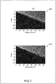
- the microphone array is in a single or double circular form, there will be a frequency range in which the value of a mode function, that is, the value of a Bessel function is zero, as illustrated in Fig. 1 .
- Fig. 1 the horizontal axis represents a wavenumber, and the vertical axis represents an order of a spherical harmonic domain. Further, light and dark in Fig. 1 represents a value of a Bessel function, and, in particular, a region of a portion in black indicates a region in which the value of a Bessel function is 0 (zero).
- the value of a Bessel function illustrated in Fig. 1 is a maximum value from among values of a Bessel function for each microphone included in the microphone array.
- the value of a Bessel function for each microphone varies depending on a distance from the center of the microphone array to the microphone.
- a portion indicated by an arrow Q11 represents a value of a Bessel function in each region that corresponds to a wavenumber and an order when the microphone array is in a single circular form.
- the value of a Bessel function is zero in many regions such as the region indicated by the arrow Q11, and this shows that there is a frequency range in which wavefront is not accurately recorded or reproduced.
- a portion indicated by an arrow Q12 represents a value of a Bessel function in each region that corresponds to a wavenumber and an order when the microphone array is in a double circular form.
- This example shows that a region in which the value of a Bessel function is zero is smaller than that in the example indicated by the arrow Q11.
- the value of a Bessel function there exists a large number of small values close to zero, and this may affect recording and reproduction of wavefront badly.
- a cardioid directional microphone as the microphone included in the microphone array makes it possible to reduce a region in which the value of a Bessel function is zero, but this results in a high cost.
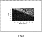
- the horizontal axis represents a wavenumber
- the vertical axis represents an order of a spherical harmonic domain.
- light and dark in Fig. 2 represents a value of a mode function, that is, a value of a Bessel function, and, in particular, a region of a portion in black indicates a region in which the value of a Bessel function is 0 (zero).
- the value of a Bessel function illustrated in Fig. 2 is a maximum value from among values of a Bessel function for each microphone included in the microphone array.
- the microphone included in the microphone array is hereinafter also specifically referred to as a mike unit.
- a spherical harmonic coefficient a mn (k) is obtained by sampling a sound pressure p k (r, ⁇ q , ⁇ q ) of the wavefront at Q respective points under the condition that the conditions of the sampling theorem are satisfied.
- a component that is included in the sound pressure p k (r, ⁇ q , ⁇ q ) and depends on a radius r of the circular microphone array is removed by dividing the sound pressure by b n (kr), which is a component depending on the radius r.
- the spherical harmonic coefficient a mn (k) can be obtained using Formula (1) below.
- n and m each represent an order of a spherical harmonic domain
- a sampling point represented by the index q is hereinafter also referred to as a point q.
- k represents a wavenumber
- r represents a radius of the circular microphone array, that is, a distance from a center position of the circular microphone array to a mike unit.
- ⁇ q and ⁇ q respectively represent an elevation and an azimuth that each indicate a direction in which a mike unit situated at a point q is oriented.
- f represents a frequency
- c s represents a speed of sound
- b n (kr) represents a mode function
- Y *m n ( ⁇ q , ⁇ q ) represents a spherical harmonic basis.
- b n (kr) is a spherical Bessel function.
- b n (kr) is hereinafter also simply referred to as a Bessel function.
- "*" in the spherical harmonic basis Y *m n ( ⁇ q , ⁇ q ) represents a complex conjugate.
- a circular microphone array includes an omnidirectional microphone is disclosed in detail in, for example, " B. Rafaely, Fundamentals of Spherical Array Processing, Springer, 2015 .” (hereinafter also referred to as Reference Document 1).
- operation processing in Formula (1) and, in particular, division processing of performing division by the Bessel function b n (kr) in Formula (1) is also referred to as mode compensation.
- mode compensation is disclosed in detail in, for example, " D. P. Jarrett, E. A. Habets and P. A. Naylor, Theory and Applications of Spherical Microphone Array Processing, Springer, 2017 .” (hereinafter also referred to as Reference Document 2).
- the spherical harmonic coefficient a mn (k) can be obtained by use of the obtained sound pressure p k (r, ⁇ q , ⁇ q ) using Formula (1). Further, when the spherical harmonic coefficient a mn (k) obtained as described above is transmitted to a reproduction system, the reproduction system can reproduce wavefront of sound (a sound field) using the spherical harmonic coefficient a mn (k).
- a numerical problem called a Bessel zero problem occurs when the value of the Bessel function b n (kr) in Formula 1 is close to zero.
- a condition number of a transformation matrix used to obtain the spherical harmonic coefficient a mn (k) becomes large when the value of the Bessel function b n (kr) gets close to zero, and this results in being unable to obtain an accurate spherical harmonic coefficient a mn (k).
- the sound pressure p k (r q , ⁇ q , ⁇ q ) sampled at the point q is represented by Formula (2) below.
- the radius r q of a mike unit corresponds to a distance from the center of the circular microphone array to the mike unit, that is, a distance from the center of the circular microphone array to the point q.
- the spherical harmonic coefficient a mn (k) of each order and wavenumber is obtained by multiplying, by B + k , a distribution of the sound pressures p k (r q , ⁇ q , ⁇ q ) obtained at the respective points q, that is, a vector p k made up of the sound pressures p k (r q , ⁇ q , ⁇ q ), where B + k is a pseudo-inverse matrix of a transformation matrix B k .
- a vector a(k) made up of the spherical harmonic coefficients a mn (k) of the wavenumber k can be obtained by performing calculation of Formula (3) below.
- a k B k + p k
- B + k represents a pseudo-inverse matrix of the transformation matrix B k .
- 1 represents an index indicating a sampling point of a sound pressure, and 1 corresponds to q described above.
- the transformation matrix B k is a matrix of which an element is a product of a Bessel function b n (kr l ) and a spherical harmonics Y m n ( ⁇ l , ⁇ l ) with respect to the order n of each point l, where 0 ⁇ n ⁇ N.
- condition number X(k) of the transformation matrix B k is favorably smaller, and a small condition number X(k) indicates a high tolerance for an error, that is, an improved robustness against an error.
- a matrix of which a condition number is more than 100 is ill-conditioned, although it depends on an application. Note that analysis of tolerance for an error of a circular microphone array or a spherical microphone array that is performed on the basis of a condition number, is disclosed in detail in, for example, Reference Document 1 described above.
- the spherical harmonic coefficient a mn (k) used to reproduce wavefront of sound can be obtained by performing calculation of Formula (3), and a well-conditioned transformation matrix B k can be obtained by appropriately setting the arrangement of each mike unit included in the microphone array and a maximum value of the order n (a maximum order) of a spherical harmonic domain.
- the present technology makes it possible to achieve a high tolerance for noise (a high tolerance for an error) over a wide frequency range using fewer omnidirectional mike units, that is, at low cost, by appropriately setting the arrangement of a mike unit and a maximum order of a spherical harmonic domain.
- recording and reproduction of wavefront according to the present technology is performed by parametrically designing a microphone array having features described below and by performing spatial resolution control depending on frequency.
- a microphone array according to the present technology has Features F1 to F3 below.
- the microphone array according to the present technology is designed on the basis of Features F1 to F3 below.
- the microphone array includes a plurality of geometrically similar sub-arrays, and each sub-array is discretely rotationally symmetric.
- the mike units are distributed at an equal angle as viewed from the center of the microphone array.
- the progression is a generalized arithmetic progression.
- the microphone array according to the present technology includes a plurality of sub-arrays, and each sub-array includes a plurality of mike units.
- the microphone array may include a single sub-array, or the sub-array may include a single mike unit.
- all of the mike units included in the microphone array are essentially omnidirectional microphones, but some of the mike units may be microphones that are not omnidirectional ones.
- Feature F1 described above is a feature in which, when the microphone array includes a plurality of sub-arrays, all of the sub-arrays have geometrically similar shapes (are in similar mike-unit arrangements).
- sub-arrays being geometrically similar to one another refers to pluralities of mike units included in the sub-arrays being in similar arrangements.
- two sub-arrays being geometrically similar to each other refers to one of the sub-arrays coinciding with the other sub-array when at least one of an enlargement operation, a reduction operation, a rotation operation, or a reverse operation is performed on the one of the sub-arrays.
- the coinciding refers to an arrangement position of each mike unit included in one of the sub-arrays coinciding with an arrangement position of each mike unit included in the other sub-array after the operation of, for example, enlargement is performed on the one of the sub-arrays.
- a center position of each sub-array coincides with a center position of the microphone array.
- each sub-array has a discretely rotationally symmetric shape.
- the sub-array does not have continuous rotational symmetry in which the sub-array constantly has the same shape when the sub-array is rotated by an arbitrary angle, but the sub-array has discrete rotational symmetry in which the shapes of the sub-array before and after being rotated coincide when the sub-array is rotated by a specified angle about a center position of the sub-array, that is, a center position of the microphone array.
- the microphone array it is possible to achieve flat frequency characteristics since each sub-array is discretely rotationally symmetric.
- each sub-array has a specified radius.
- all of the mike units included in the sub-array have an equal radius, and this radius corresponds to a radius of the sub-array.
- the radius of a mike unit corresponds to a distance from a center position of the sub-array, that is, from a center position of the microphone array to the mike unit.
- each of the plurality of mike units included in the sub-array is arranged away from the center position of the microphone array, that is, the center position of the sub-array by a distance corresponding to the radius of the sub-array.
- Feature F2 is a feature in which, when all of the mike units included in the microphone array are radially projected onto a single ring shape centered at a center position of the microphone array, that is, onto the circumference of the microphone array, the projected mike units are uniformly distributed on the ring shape. In other words, the projected mike units are equally spaced on the ring shape.
- the position on a ring shape at which a mike unit is projected is a position at which a line connecting (passing through) the mike unit and the center position of the microphone array intersects a ring shape (a circle) onto which the mike unit is projected.
- the position of a mike unit on a ring shape as viewed from the center position of the microphone array is a position onto which the mike unit is projected.
- Feature F3 is a feature in which, when there exist sub-arrays, from among a plurality of sub-arrays included in the microphone array, that have different radiuses, and when values of radiuses of all of the sub-arrays included in the microphone array form a progression, the progression is a generalized arithmetic progression, the values of the radiuses being placed in ascending order or in descending order.
- Feature 3 is a feature in which mike units are arranged at intervals corresponding to a common difference of a generalized arithmetic progression in a direction outward from the center of the microphone array, that is, in a direction away from the center.
- a method for arranging mike units on the basis of a distance corresponding to a radius determined according to a logarithm or a geometric progression are disclosed in detail in, for example, " Z. Prime and C. Doolan, "A comparison of popular beamforming arrays", Proceedings of Acoustics 2013 Victor Harbor: Science Technology and Amenity, Annual Conference of the Australian Acoustical Society, 2013 .” and United States Patent No. 6205224 .
- the microphone array designed to have Features F1 and F2 makes it possible to achieve scalable use depending on requirements by using several sub-arrays.
- the microphone array includes three sub-arrays when there is a sufficiently large number of available mike units, and the microphone array includes two sub-arrays when there is a small number of available mike units, is possible.
- the transformation matrix B k of the microphone array depends on the frequency, that is, the wavenumber k, and spatial resolution for conversion is appropriately set for each frequency in an operation frequency range in order to obtain accurate sound-field information.
- a more accurate spherical harmonic coefficient a mn (k) is generally obtained at a higher spatial resolution if calculation is performed up to a term of a higher order n.
- the value of a Bessel function is zero or close to zero.
- processing of excluding (removing), from the transformation matrix B k , a row corresponding to each of the orders n not less than a specified order is performed as spatial resolution control, in order to improve the condition number of the transformation matrix B k .
- limitation is placed on the order n used to perform operation, that is, the number of rows of the transformation matrix B k is limited.
- the advantage the present technology has is that it is possible to record a broadband sound field (wavefront) while achieving a high tolerance for an error, using a minimum number of omnidirectional mike units.
- the spatial resolution control makes it possible not only to improve tolerance for an error, but also to reduce a calculation amount.
- the inclusion of a plurality of sub-arrays in a microphone array makes it possible to increase the sampling density in an angular direction without using a small mike unit.
- the reason is that, for example, compared to when mike units are arranged in a single circular form, the arrangement of a plurality of sub-arrays makes it possible to further increase the density of projected mike units on a ring shape centered at a center position of a microphone array when the mike units are radially projected onto the ring shape.
- the microphone array according to the present technology has a self-similar shape, that is, a fractal shape.
- the present technology achieves the scalability that makes it possible to form a microphone array even when only fewer number of mike units can be used. In other words, scalable use is possible as described above.
- FIG. 3 illustrates an example of a configuration of an embodiment of a microphone array according to the present technology.
- a microphone array MA11 illustrated in Fig. 3 is a vortex-shaped microphone array that includes a plurality of omnidirectional mike units. Note that, in Fig. 3 , each point represents one mike unit.
- the microphone array MA11 includes 128 mike units, and these mike units are arranged in the form of a vortex.
- one sub-array includes 16 mike units.
- the microphone array MA11 includes eight sub-arrays having different radiuses, and the eight sub-arrays are concentrically arranged.
- a sub-array SA11 is a portion including 16 circularly arranged mike units
- a sub-array SA12 is a portion including 16 circularly arranged mike units.
- the microphone array MA11 has Features F1 to F3 described above.
- the respective sub-arrays included in the microphone array MA11 have shapes that are different only in a scale and a rotation angle. Specifically, for example, when the sub-array SA11 is enlarged and rotated by a specified angle, the enlarged and rotated sub-array SA11 coincides with the sub-array SA12.
- mike units of each sub-array are arranged in the form of a circle centered at a center position 011, and this results in the sub-array having a discretely rotationally symmetric shape.
- FIG. 4 An enlarged view of a portion of the microphone array MA11 is given in Fig. 4 .
- each circle represents one mike unit.
- the same number is given in circles that respectively represent mike unites included in the same sub-array.
- a mike unit given a number "1" is included in the sub-array SA11 illustrated in Fig. 3
- a mike unit given a number "8" is included in the sub-array SA12 illustrated in Fig. 3 .
- this example shows that the respective sub-arrays are adjacently arranged and a progression containing values of radiuses of these sub-arrays is a generalized arithmetic progression.
- a difference between radiuses of adjacent sub-arrays exhibits one of several predetermined values corresponding to a common difference.
- the microphone array MA11 illustrated in Fig. 3 is hereinafter also specifically referred to as a vortex-shaped microphone array.
- the microphone array includes eight sub-arrays and the sub-arrays each include 16 mike units, has been described above.
- the microphone array may include four sub-arrays and each sub-array may include 32 mike units, or the microphone array may include two sub-arrays and each sub-array may include 64 mike units.
- the microphone array according to the present technology is not limited to the microphone array illustrated in Fig.3 , and may have any configuration, as long as it has Features F1 to F3.
- the microphone array may have the configuration illustrated in Fig. 5 .
- a microphone array MA21 formed by a plurality of omnidirectional mike units being arranged in the form of an outline of a flower is illustrated in a portion indicated by an arrow Q31 in Fig. 5 . Note that, in the portion indicated by the arrow Q31, each point represents one mike unit.
- the microphone array MA21 includes eight sub-arrays, and each sub-array includes 16 circularly arranged mike units.
- each circle represents one mike unit, and the same number is given in circles that respectively represent mike unites included in the same sub-array.
- This example shows that the eight sub-arrays included in the microphone array MA21 are concentrically arranged and the respective sub-arrays are adjacently arranged.
- this example shows that the sub-array including mike units given a number "2" and the sub-array including mike units given a number "8" are different in an angle of rotation centered at a center position of the microphone array MA21, that is, in an arrangement position of a mike unit in a rotational direction, but the sub-arrays have an equal radius.
- the sub-array including mike units given a number "3" and the sub-array including mike units given a number "7" are different in an angle of rotation, but have an equal radius.
- the sub-array including mike units given a number "4" and the sub-array including mike units given a number "6" are different in an angle of rotation, but have an equal radius.
- Such a microphone array MA21 has Features F1 to F3 described above. Note that the microphone array MA21 is hereinafter also specifically referred to as a flower-shaped microphone array.
- the microphone array according to the present technology may have the configuration illustrated in, for example, Fig. 6 , 7 , or 8 .
- a microphone array MA31 formed by a plurality of omnidirectional mike units being arranged substantially in the form of a vortex is illustrated in a portion indicated by an arrow Q41 in Fig. 6 . Note that, in the portion indicated by the arrow Q41, each point represents one mike unit.
- the microphone array MA31 includes eight sub-arrays, and each sub-array has Feature 1 described above. Further, each sub-array includes 16 circularly arranged mike units.
- each circle represents one mike unit, and the same number is given in circles that respectively represent mike unites included in the same sub-array.
- the eight sub-arrays included in the microphone array MA31 are concentrically arranged, and the rotation angle of each sub-array upon arranging the sub-array is determined at random.
- a microphone array MA41 formed by a plurality of omnidirectional mike units being arranged substantially in the form of a vortex is illustrated in a portion indicated by an arrow Q51 in Fig. 7 . Note that, in the portion indicated by the arrow Q51, each point represents one mike unit.
- the microphone array MA41 includes eight sub-arrays, and each sub-array includes 16 circularly arranged mike units.
- each circle represents one mike unit, and the same number is given in circles that respectively represent mike unites included in the same sub-array.
- the eight sub-arrays included in the microphone array MA41 are concentrically arranged, and the rotation angle of each sub-array upon arranging the sub-array is determined at random.
- the rotation angle of each sub-array is determined at random, and the microphone arrays illustrated in Figs. 6 and 7 each have Features F1 to F3 described above. Note that such microphone arrays are hereinafter also specifically referred to as randomly shaped microphone arrays.
- a microphone array MA51 formed by a plurality of omnidirectional mike units being arranged in a triple circular form is illustrated in Fig. 8 . Note that, in Fig. 8 , each point represents one mike unit.
- the microphone array MA51 includes three sub-arrays, and each sub-array includes 43 circularly arranged mike units.
- the three sub-arrays included in the microphone array MA51 are concentrically arranged, and, when one of the three sub-arrays is enlarged or reduced, and then rotated, the one of the three sub-arrays coincides with the other sub-arrays.
- the microphone array having Features F1 to F3 described above makes it possible to reduce a region in which the value of a Bessel function is zero, and to improve the condition number X(k) of the transformation matrix B k .
- the adoptions of the vortex-shaped microphone array, the flower-shaped microphone array, and the randomly shaped microphone array each result in there being no region in which the value of a Bessel function is zero, as illustrated in Fig. 9 .
- the horizontal axis represents a wavenumber
- the vertical axis represents an order of a spherical harmonic domain.
- light and dark in Fig. 9 represents a value of a Bessel function, and, in particular, a region of a portion in black indicates a region in which the value of a Bessel function is 0 (zero). More specifically, the value of a Bessel function illustrated in Fig. 9 is a maximum value from among values of a Bessel function for each sub-array included in a microphone array.
- a portion indicated by an arrow Q61 represents a value of a Bessel function in each region that corresponds to the wavenumber k and the order n when the vortex-shaped microphone array is used.
- a portion indicated by an arrow Q62 represents a value of a Bessel function in each region that corresponds to the wavenumber k and the order n when the flower-shaped microphone array is used.
- a portion indicated by an arrow Q63 represents a value of a Bessel function in each region that corresponds to the wavenumber k and the order n when the randomly shaped microphone array is used.
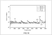
- the condition of the transformation matrix B k is better if mike units projected onto a ring shape are situated closer to each other, as illustrated in, for example, Fig. 10 .
- the horizontal axis represents a frequency
- the vertical axis represents the condition number X(k) of the transformation matrix B k .
- the condition number X(k) is a condition number when spatial resolution control described later is performed.
- a curve L11 to a curve L14 respectively represent the condition numbers X(k) for the vortex-shaped microphone array MA11 illustrated in Fig. 3 , the flower-shaped microphone array MA21 illustrated in Fig. 5 , the randomly shaped microphone array MA31 illustrated in Fig. 6 , and the randomly shaped microphone array MA41 illustrated in Fig. 7 .
- this example shows that the condition number X(k) for the flower-shaped microphone array MA21 is smallest over an entire frequency range since the distance between mike units projected onto a ring shape is shortest in the case of the flower-shaped microphone array MA21.
- the distance between mike units is relatively long for every eight mike units.
- a mike unit included in a sub-array that is included in the microphone array MA11 and situated closest to the center, and a mike unit included in a sub-array situated farthest away from the center are arranged away from each other.
- the distance between mike units projected onto a ring shape is longer than that in the case of the microphone array MA21, and the condition number X(k) for the vortex-shaped microphone array MA11 is slightly larger than the condition number X(k) for the flower-shaped microphone array MA21.
- the distance between mike units projected onto a ring shape is relatively long.
- the condition numbers X(k) for the microphone arrays MA31 and MA41 are larger than the condition number X(k) for the vortex-shaped microphone array MA11.
- the present technology makes it possible to parametrically determine the arrangement of each mike unit in a microphone array.
- a parameter that indicates the arrangement of each mike unit of a microphone array is referred to as an arrangement parameter, and a set of a plurality of arrangement parameters is referred to as an arrangement-parameter set.
- the arrangement of each mike unit included in a microphone array is determined by the arrangement-parameter set.
- the number of sub-arrays S is the number of sub-arrays included in a microphone array
- the radius r s of a sub-array corresponds to a distance from a center position of a microphone array to a mike unit included in the sub-array.
- a vector containing radiuses r s of S sub-arrays is hereinafter also referred to as a radius vector r sub .
- the rotation angle ⁇ s of a sub-array is an angle of inclination of the sub-array with respect to a specified direction as viewed from a center position of a microphone array.
- the rotation angle ⁇ s of a sub-array is an angle of a rotational direction that indicates the position of the sub-array in a direction of rotation centered at a center position of a microphone array.
- the center position of a microphone array is a center 0, and a direction, as viewed from the center 0, that is used as a specified reference is a reference direction.
- the rotation angle ⁇ s is an angle between a line connecting the center 0 and a mike unit that is included in the sub-array and used as a specified reference, and the reference direction.
- a direction of a mike unit that is included in a sub-array situated closest to the center 0 and is used as a reference is set to be the reference direction.
- the rotation angle ⁇ s of a sub-array indicates by which angle another sub-array situated closest to the center 0 is to be rotated such that the other sub-array coincides with the sub-array.
- a vector containing rotation angles ⁇ s of S sub-arrays is hereinafter also referred to as a rotation-angle vector ⁇ sub .
- an optimal arrangement parameter depends on a total number of microphone units Q, an operation frequency range [f min , f max ], a diameter of a mike unit D m , and an upper limit X max of the condition number X(k).
- the total number of microphone units Q is the number of mike units included in a microphone array.
- the number of sub-arrays included in the microphone array, that is, the number of sub-arrays S is determined by the total number of microphone units Q.
- a value of the number of sub-arrays S can be set to be 1, 2, 3, 4, 6, 12, or 24.
- the operation frequency range [f min , f max] is a frequency range from a minimum value f min to a maximum value f max of a frequency of a target sound.
- each arrangement parameter is optimized considering a condition number in the operation frequency range [f min , f max ].
- the diameter D m of a mike unit is a diameter of a mike unit included in a microphone array, and D m is a lower limit of an absolute value of a common difference of a generalized arithmetic progression that determines the radius vector r sub .
- the radiuses r s of two arbitrary sub-arrays are a radius ri and a radius r j (where i ⁇ j).
- the radius ri and the radius r j satisfy Formula (7) below.
- the reason is that, even if the radius r s of a sub-array and the rotation angle ⁇ s are considered, it is not possible to physically arrange two mike units having the diameter D m side by side unless the condition of Formula (7) is satisfied.
- r i ⁇ r j ⁇ r j cos 2 ⁇ Q ⁇ 1 + D m r j 2 ⁇ sin 2 2 ⁇ Q , i ⁇ j
- the upper limit X max is a value of the condition number X(k) that is acceptable in the operation frequency range [f min , f max] and indicates a state of being best-conditioned (a largest value of the condition number X(k)).
- a microphone array including appropriately arranged mike units by determining an optimal arrangement-parameter set P Q opt on the basis of the total number of microphone units Q, the operation frequency range [f min , f max ], the diameter D m of a mike unit, and the upper limit X max of the condition number X(k) described above, such that the microphone array has Features F1 to F3.
- the optimal arrangement-parameter set P Q opt is obtained by minimizing an average condition number of the transformation matrix B k in the operation frequency range [f min , f max ], with constraints imposed by the total number of microphone units Q, the diameter D m , and the upper limit X max .
- a search for the arrangement-parameter set P Q opt is achieved by performing an exhaustive search for possible arrangement parameters.
- a substantially optimal result can be obtained by a metaheuristic optimization approach such as differential evolution.
- n 0 kr ⁇ N arr Q ⁇ 1 / 2
- spherical harmonic terms that is, elements of the transformation matrix B k that correspond to the order n up to N arr , which is greater than n 0 (kr) do not include reliable information for reproducing wavefront.
- the value of the Bessel function is zero or nearly zero.
- processing of limiting the number of rows of the transformation matrix B k is performed as spatial resolution control, the number of rows of the transformation matrix B k being the number of rows used to perform operation to calculate the spherical harmonic coefficient a mn (k), the operation including mode compensation.
- a transformation matrix B n0 k obtained by performing spatial resolution control on the transformation matrix B k is a matrix that contains the first row to the n 0 (k ⁇ max(r s ))-th row of the transformation matrix B k .
- the number of rows of the transformation matrix B k that are used to perform operation is limited to n 0 (k ⁇ max(r s )) rows on the basis of an order n 0 (k ⁇ max(r s )), and the transformation matrix B n0 k is obtained as a transformation matrix in which the number of rows is limited.
- the n 0 (k ⁇ max(r s ))-th row of the transformation matrix B k is a row corresponding to the order n 0 (k ⁇ max(r s )).
- the order n 0 (k ⁇ max(r s )) is an order with respect to a sub-array having a radius of max(r s ).
- the threshold th in Formula (9) is a real number between zero and one, and a value close to one is favorable. Specifically, for example, the threshold th is set to 0.95. Further, in Fig. 3 , Figs. 5 to 8 , and Fig. 10 described above, and in Fig. 12 described later, an order n 0 (kr s ) that is defined using Formula (9) is used in all of the figures.
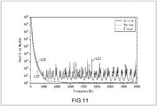
- the respective condition numbers X(k) of the transformation matrix B k exhibit values illustrated in Fig. 11 .
- the horizontal axis represents a frequency
- the vertical axis represents the condition number X(k).
- a curve L21 to a curve L23 respectively represent the condition numbers of the circular microphone array, the vortex-shaped microphone array MA11 illustrated in Fig. 3 , and the flower-shaped microphone array MA21 illustrated in Fig. 5 .
- This example shows that the condition numbers X(k) of the transformation matrix B k for all of the microphone arrays are large in a low-frequency range.
- This phenomenon occurs due to linear dependency caused by a redundant row of the transformation matrix B k , and the microphone array according to the present technology makes it possible to cope with the phenomenon by performing spatial resolution control or an appropriate matrix regularization.
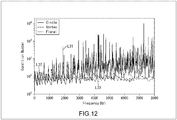
- the respective condition numbers X(k) of transformation matrix B n0 k exhibit values illustrated in Fig. 12 .
- the horizontal axis represents a frequency
- the vertical axis represents the condition number X(k).
- a curve L31 to a curve L33 respectively represent the condition numbers of the circular microphone array, the vortex-shaped microphone array MA11 illustrated in Fig. 3 , and the flower-shaped microphone array MA21 illustrated in Fig. 5 .
- This example shows that the condition numbers X(k) of the transformation matrix B n0 k for all of the microphone arrays are smaller in a low-frequency range, compared to the example of Fig. 11 .
- condition number X(k) for the circular microphone array is large depending on frequency.
- Such worsening of the condition of the circular microphone array is its specific feature due to the value of a Bessel function becoming zero, and it is not solved by performing spatial resolution control or matrix regularization.
- the respective condition numbers X(k) are not greater than 30 at most frequencies. This result shows that a better condition number is obtained by performing spatial resolution control on a microphone array with an appropriate mike-unit arrangement and tolerance for an error is improved.
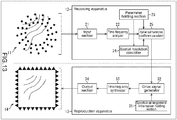
- Such a recording system and such a reproduction system are configured as illustrated in Fig. 13 .
- the recording system includes a microphone array 11 and a recording apparatus 12, and the reproduction system includes a reproduction apparatus 13 and a speaker array 14.
- the microphone array 11 may be part of the recording apparatus 12, and the speaker array 14 may be part of the reproduction apparatus 13.
- wavefront of sound is recorded by the microphone array 11 including a plurality of mike units, and a multichannel signal that is a signal of the sound that is obtained as a result of the recording is supplied to the recording apparatus 12.
- the microphone array 11 records wavefront of sound by collecting the sound using respective mike units, and outputs, as a multichannel signal, a signal that is an audio signal obtained by the collection of the sound performed using the respective mike units.
- the microphone array 11 is used to record a sound field, that is, wavefront of sound, and includes a plurality of sub-arrays. Further, each sub-array includes a plurality of mike units.
- the microphone array 11 is a microphone array that has Features F1 to F3 described above, such as the microphone arrays illustrated in Fig. 3 and Figs. 5 to 8, and the mike unit included in the microphone array 11 is an omnidirectional microphone.
- the recording apparatus 12 calculates the spherical harmonic coefficient a mn (k) using a multichannel signal supplied by the microphone array 11, and supplies the spherical harmonic coefficient a mn (k) to the reproduction apparatus 13.
- the recording apparatus 12 includes an input section 21, a time-frequency analyzer 22, a parameter holding section 23, a spatial resolution controller 24, and a spherical harmonic coefficient calculator 25.
- the input section 21 performs analog-to-digital (AD) conversion on the multichannel signal supplied by microphone array 11 to convert the analog multichannel signal to a digital signal, and supplies the digital signal to the time-frequency analyzer 22.
- AD analog-to-digital
- the time-frequency analyzer 22 performs short-time Fourier transform (STFT) on the multichannel signal supplied by the input section 21, and supplies a time-frequency spectrum obtained as a result of performing the short-time Fourier transform to the spherical harmonic coefficient calculator 25.
- STFT short-time Fourier transform
- the time-frequency spectrum obtained by the time-frequency analyzer 22 corresponds to the sound pressure p k (r l , ⁇ l , ⁇ l ) indicated in Formula (4) .
- the parameter holding section 23 holds the arrangement-parameter set P Q opt determined on the basis of, for example, the total number of microphone units Q, the operation frequency range [f min , f max ], the diameter D m of a mike unit, and the upper limit X max of the condition number X(k) that are given in advance.
- the microphone array 11 is a microphone array having a shape determined by the arrangement-parameter set P Q opt determined as described above, and the arrangement-parameter set P Q opt related to the microphone array 11 is held by the parameter holding section 23.
- the arrangement-parameter set P Q opt is geometry information indicating the mike-unit arrangement of the microphone array 11.
- the parameter holding section 23 supplies the arrangement-parameter set P Q opt held in the parameter holding section 23 to the spatial resolution controller 24 and the spherical harmonic coefficient calculator 25.
- the spatial resolution controller 24 controls spatial resolution on the basis of the arrangement-parameter set P Q opt supplied by the parameter holding section 23.
- the spatial resolution controller 24 performs calculation of, for example, Formula (9) described above for each frequency, that is, for each wavenumber K to calculate (determine) the order no(kxmax(r s )). Then, the spatial resolution controller 24 supplies the order n 0 (k ⁇ max(r s )) obtained as described above to the spherical harmonic coefficient calculator 25, and instructs the spherical harmonic coefficient calculator 25 to limit the number of rows of the transformation matrix B k .
- the spherical harmonic coefficient calculator 25 calculates the spherical harmonic coefficient a mn (k) using the time-frequency spectrum supplied by the time-frequency analyzer 22, the arrangement-parameter set P Q opt supplied by the parameter holding section 23, and the order n 0 (k ⁇ max(r s )) supplied by the spatial resolution controller 24.
- the spherical harmonic coefficient calculator 25 generates the transformation matrix B n0 k in which the number of rows is limited, in accordance with the instruction given by the spatial resolution controller 24. Specifically, as the transformation matrix B n0 k that is a final matrix, the spherical harmonic coefficient calculator 25 generates a matrix containing the first row to the n 0 (k ⁇ max(r s ))-th row of the transformation matrix B k determined according to the arrangement-parameter set P Q opt , that is, the mike-unit arrangement of the microphone array 11.
- This transformation matrix B n0 k is generated for each wavenumber K, that is, for each STFT bin, on the basis of the arrangement-parameter set P Q opt that is geometry information of the microphone array 11, and the order n 0 (k ⁇ max(r s )) that is output of the spatial resolution controller 24.
- the spherical harmonic coefficient calculator 25 performs calculation as that of Formula (3) described above, on the basis of a pseudo-inverse matrix obtained with respect to the transformation matrix B n0 k , and on the basis of the time-frequency spectrum, and calculates the spherical harmonic coefficient a mn (k).
- the spherical harmonic coefficient calculator 25 uses the Moore-Penrose inverse as a pseudo-inverse matrix of the transformation matrix B n0 k .
- the Moore-Penrose inverse with respect to the transformation matrix B n0 k is calculated as a pseudo-inverse matrix of the transformation matrix B n0 k .
- the spherical harmonic coefficient calculator 25 performs calculation similar to that of Formula (3) described above, and spherical harmonic transform (SHT) and mode compensation are performed at the same time in this calculation.
- the mode compensation in this case is processing corresponding to dividing p k (r, ⁇ q , ⁇ q ) Y *m n ( ⁇ q , ⁇ q ) by b n (kr) in Formula (1), that is, processing of dividing, by a mode function (a Bessel function), a time-frequency spectrum on which spherical harmonic transform has been performed.
- the spherical harmonic coefficient calculator 25 is provided with a processing block for performing spherical harmonic transform and a processing block for performing mode compensation. Then, in the processing block for performing spherical harmonic transform, spherical harmonic transform is performed on a time-frequency spectrum, and, in the processing block for performing mode compensation, the time-frequency spectrum on which spherical harmonic transform has been performed is divided by a mode function (a Bessel function).
- a mode function a Bessel function
- the spherical harmonic coefficient calculator 25 outputs (transmits) the calculated spherical harmonic coefficient a mn (k) to the reproduction system.
- a drive signal used to drive the speaker array 14 is generated on the basis of the spherical harmonic coefficient a mn (k) output by the spherical harmonic coefficient calculator 25, and wavefront of sound is reproduced.
- the generation of a drive signal can be performed by correcting speaker characteristics of the speaker array 14 or by using the other algorithms.
- the reproduction apparatus 13 of the reproduction system includes a speaker-arrangement-information holding section 31, a drive signal generator 32, a time-frequency synthesizer 33, and an output section 34.
- the speaker-arrangement-information holding section 31 holds speaker arrangement information that indicates the arrangement of a speaker included in the speaker array 14, and supplies the held speaker arrangement information to the drive signal generator 32.
- the drive signal generator 32 receives the spherical harmonic coefficient a mn (k) transmitted by the spherical harmonic coefficient calculator 25, generates a drive signal on the basis of the received spherical harmonic coefficient a mn (k) and the speaker arrangement information supplied by the speaker-arrangement-information holding section 31, and supplies the generated drive signal to the time-frequency synthesizer 33.
- the drive signal generator 32 performs calculation of Formula (2) described above, and a signal that represents the sound pressure p k (r q , ⁇ q , ⁇ q ) is calculated as a drive signal in the time frequency domain. Note that, in the calculation of Formula (2), the value of a radius of a reproduction area that is a region for which wavefront of sound is reproduced is used as the radius r q .
- spherical harmonic coefficient a mn (k) by a Bessel function that is, generation of a drive signal in a spherical harmonic domain
- inverse spherical harmonic transform may be performed after a drive signal in a spherical harmonic domain is generated.
- the drive signal generator 32 is provided with a processing block for generating a drive signal in a spherical harmonic domain and a processing block for performing inverse spherical harmonic transform.
- the time-frequency synthesizer 33 performs inverse short-time Fourier transform (ISTFT) on the drive signal supplied by the drive signal generator 32, and supplies, to the output section 34, a drive signal in the time domain that is obtained as a result of performing the inverse short-time Fourier transform.
- ISTFT inverse short-time Fourier transform
- the output section 34 performs digital-to-analog conversion on the drive signal supplied by the time-frequency synthesizer 33, and supplies, to the speaker array 14, an analog drive signal obtained as a result of performing the digital-to-analog conversion.
- the speaker array 14 outputs sound on the basis of the drive signal supplied by the output section 34 to reproduce wavefront of the sound that is recorded by the recording system.
- the speaker array 14 is obtained by rectangularly arranging linear speaker arrays, each linear speaker array being obtained by linearly arranging speakers, and a region situated inside the speaker array 14 is a reproduction area for wavefront.
- the speaker array 14 may have any shape, that is, the speaker array 14 may have any speaker arrangement.
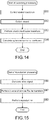
- Step S11 the spatial resolution controller 24 controls spatial resolution on the basis of the arrangement-parameter set P Q opt supplied by the parameter holding section 23.
- the spatial resolution controller 24 performs calculation of, for example, Formula (9) described above to calculate the order n 0 (k ⁇ max(r s )), supplies the calculated order n 0 (k ⁇ max(r s )) to the spherical harmonic coefficient calculator 25, and instructs the spherical harmonic coefficient calculator 25 to limit the number of rows of the transformation matrix B k .
- Step S12 the microphone array 11 collects ambient sound using a mike unit, and supplies a multichannel signal obtained as a result of the collection to the input section 21.
- the input section 21 performs AD conversion on the multichannel signal supplied by the microphone array 11, and supplies, to the time-frequency analyzer 22, the multichannel signal on which the AD conversion has been performed.
- Step S13 the time-frequency analyzer 22 performs short-time Fourier transform on the multichannel signal supplied by the input section 21, and supplies a time-frequency spectrum obtained as a result of performing the short-time Fourier transform to the spherical harmonic coefficient calculator 25.
- the spherical harmonic coefficient calculator 25 calculates the spherical harmonic coefficient a mn (k) on the basis of the time-frequency spectrum from the time-frequency analyzer 22, the arrangement-parameter set P Q opt from the parameter holding section 23, and the order n 0 (k ⁇ max(r s )) from the spatial resolution controller 24.
- the spherical harmonic coefficient calculator 25 generates the transformation matrix B n0 k on the basis of the order n 0 (k ⁇ max(r s )), in accordance with the instruction given by the spatial resolution controller 24, and calculates a pseudo-inverse matrix of the generated transformation matrix B n0 k . Then, the spherical harmonic coefficient calculator 25 performs calculation similar to that of Formula (3) on the basis of the obtained pseudo-inverse matrix and the time-frequency spectrum, and calculates the spherical harmonic coefficient a mn (k).
- the spherical harmonic coefficient calculator 25 outputs the spherical harmonic coefficient a mn (k) calculated as described above, and the recording processing is terminated.
- the recording system records wavefront using the microphone array 11 having a shape (a mike-unit arrangement) determined according to the arrangement-parameter set P Q opt , and calculates the spherical harmonic coefficient a mn (k) using a transformation matrix obtained by controlling spatial resolution. This makes it possible to perform broadband sound field recording at low cost.
- reproduction processing performed by the reproduction system is described with reference to a flowchart of Fig. 15 .
- the reproduction processing is started when the drive signal generator 32 of the reproduction apparatus 13 receives the spherical harmonic coefficient a mn (k) transmitted by the recording system.
- Step S41 the drive signal generator 32 generates a drive signal on the basis of the received spherical harmonic coefficient a mn (k) and speaker arrangement information supplied by the speaker-arrangement-information holding section 31, and supplies the generated drive signal to the time-frequency synthesizer 33.
- Step S41 calculation of Formula (2) described above is performed, and a signal indicating the sound pressure p k (r q , ⁇ q , ⁇ q ) is calculated as a drive signal in the time frequency domain.
- Step S42 the time-frequency synthesizer 33 performs inverse short-time Fourier transform on the drive signal supplied by the drive signal generator 32, and supplies, to the output section 34, a drive signal in the time domain that is obtained as a result of performing the inverse short-time Fourier transform. Further, the output section 34 performs DA conversion on the drive signal supplied by the time-frequency synthesizer 33, and supplies, to the speaker array 14, an analog drive signal obtained as a result of performing the DA conversion.
- Step S43 the speaker array 14 outputs sound on the basis of the drive signal supplied by the output section 34 to reproduce wavefront of the sound that is recorded by the recording system, and the reproduction processing is terminated.
- the reproduction system generates a drive signal from the received spherical harmonic coefficient a mn (k), and reproduces wavefront of sound on the basis of the generated drive signal.
- the reproduction system makes it possible to perform broadband wavefront reproduction by reproducing wavefront on the basis of the spherical harmonic coefficient a mn (k) received from the recording system.
- the series of processes described above can be performed using hardware or software.
- a program included the software is installed on a computer.
- examples of the computer include a computer incorporated into dedicated hardware, and a computer such as a general-purpose personal computer that is capable of performing various functions by various programs being installed thereon.
- Fig. 16 is a block diagram of an example of a configuration of hardware of a computer that performs the series of processes described above using a program.
- a central processing unit (CPU) 501 a read only memory (ROM) 502, and a random access memory (RAM) 503 are connected to one another through a bus 504.
- CPU central processing unit
- ROM read only memory
- RAM random access memory
- an input/output interface 505 is connected to the bus 504.
- An input section 506, an output section 507, a recording section 508, a communication section 509, and a drive 510 are connected to the input/output interface 505.
- the input section 506 includes, for example, a keyboard, a mouse, a microphone array, and an imaging element.
- the output section 507 includes, for example, a display and a speaker array.
- the recording section 508 includes, for example, a hard disk and a nonvolatile memory.
- the communication section 509 includes, for example, a network interface.
- the drive 510 drives a removable recording medium 511 such as a magnetic disk, an optical disk, a magneto-optical disk, or a semiconductor memory.
- the series of processes described above is performed by the CPU 501 loading a program stored in the recording section 508 into the RAM 503 and executing the program via the input/output interface 505 and the bus 504.
- the program executed by the computer can be provided by being stored in the removable recording medium 511 serving as, for example, a package medium.
- the program can be provided via a wired or wireless transmission medium such as a local area network, the Internet, or digital satellite broadcasting.
- the program can be installed on the recording section 508 via the input/output interface 505 by the removable recording medium 511 being mounted on the drive 510. Further, the program can be received by the communication section 509 via the input/output interface 505 to be installed on the recording section 508. Moreover, the program can be installed in advance on the ROM 502 or the recording section 508.
- the program executed by the computer may be a program in which processes are chronologically performed in the order described herein, or may be a program in which processes are performed in parallel or a process is performed at a necessary timing such as a timing of calling.
- the present technology may also have a configuration of cloud computing in which a plurality of apparatuses shares tasks of a single function and works collaboratively to perform the single function via a network.
- a single step includes a plurality of processes
- the plurality of processes included in the single step may be shared by a plurality of apparatuses to be performed, in addition to being performed by a single apparatus.
- present technology may also take the following configurations.
Landscapes
- Health & Medical Sciences (AREA)
- Otolaryngology (AREA)
- Physics & Mathematics (AREA)
- Engineering & Computer Science (AREA)
- Acoustics & Sound (AREA)
- Signal Processing (AREA)
- General Health & Medical Sciences (AREA)
- Obtaining Desirable Characteristics In Audible-Bandwidth Transducers (AREA)
- Circuit For Audible Band Transducer (AREA)
Applications Claiming Priority (2)
| Application Number | Priority Date | Filing Date | Title |
|---|---|---|---|
| JP2018037373 | 2018-03-02 | ||
| PCT/JP2019/005555 WO2019167671A1 (fr) | 2018-03-02 | 2019-02-15 | Réseau de microphones, procédé et dispositif d'enregistrement, et programme |
Publications (2)
| Publication Number | Publication Date |
|---|---|
| EP3761663A1 true EP3761663A1 (fr) | 2021-01-06 |
| EP3761663A4 EP3761663A4 (fr) | 2021-05-05 |
Family
ID=67806102
Family Applications (1)
| Application Number | Title | Priority Date | Filing Date |
|---|---|---|---|
| EP19761590.9A Withdrawn EP3761663A4 (fr) | 2018-03-02 | 2019-02-15 | Réseau de microphones, procédé et dispositif d'enregistrement, et programme |
Country Status (5)
| Country | Link |
|---|---|
| US (1) | US20200413187A1 (fr) |
| EP (1) | EP3761663A4 (fr) |
| JP (1) | JPWO2019167671A1 (fr) |
| CN (1) | CN111543066A (fr) |
| WO (1) | WO2019167671A1 (fr) |
Families Citing this family (4)
| Publication number | Priority date | Publication date | Assignee | Title |
|---|---|---|---|---|
| US12010483B2 (en) * | 2021-08-06 | 2024-06-11 | Qsc, Llc | Acoustic microphone arrays |
| CN114623984A (zh) * | 2022-05-16 | 2022-06-14 | 之江实验室 | 一种基于异构麦克风阵列的声学成像仪 |
| CN115086607B (zh) * | 2022-06-14 | 2024-12-24 | 国网山东省电力公司电力科学研究院 | 一种电力施工监控系统、监控方法、计算机设备 |
| CN116437259B (zh) * | 2023-03-29 | 2025-12-09 | 苏州图灵检测科技有限公司 | 声场重建方法、装置、系统、电子设备和存储介质 |
Family Cites Families (10)
| Publication number | Priority date | Publication date | Assignee | Title |
|---|---|---|---|---|
| US6205224B1 (en) | 1996-05-17 | 2001-03-20 | The Boeing Company | Circularly symmetric, zero redundancy, planar array having broad frequency range applications |
| DK174558B1 (da) | 2002-03-15 | 2003-06-02 | Bruel & Kjaer Sound & Vibratio | Stråleformende transducer-antennesystem |
| GB2438259B (en) * | 2006-05-15 | 2008-04-23 | Roke Manor Research | An audio recording system |
| US8077540B2 (en) * | 2008-06-13 | 2011-12-13 | The United States Of America As Represented By The Secretary Of The Navy | System and method for determining vector acoustic intensity external to a spherical array of transducers and an acoustically reflective spherical surface |
| JP5175239B2 (ja) * | 2009-04-03 | 2013-04-03 | 日本放送協会 | 収音装置 |
| JP2011015050A (ja) | 2009-06-30 | 2011-01-20 | Nittobo Acoustic Engineering Co Ltd | ビームフォーミング用のアレイ、及びそれを用いた音源探査測定システム |
| US9191741B1 (en) * | 2009-08-05 | 2015-11-17 | The Boeing Company | Variable aperture phased array |
| JP5954713B2 (ja) * | 2013-03-05 | 2016-07-20 | 日本電信電話株式会社 | 音場収音再生装置、方法及びプログラム |
| CN107155344A (zh) * | 2014-07-23 | 2017-09-12 | 澳大利亚国立大学 | 平面传感器阵列 |
| JP2017055156A (ja) * | 2015-09-07 | 2017-03-16 | 日本電信電話株式会社 | 音場測定装置、音場測定方法、プログラム |
-
2019
- 2019-02-15 WO PCT/JP2019/005555 patent/WO2019167671A1/fr not_active Ceased
- 2019-02-15 CN CN201980007111.6A patent/CN111543066A/zh not_active Withdrawn
- 2019-02-15 US US16/976,044 patent/US20200413187A1/en not_active Abandoned
- 2019-02-15 JP JP2020503393A patent/JPWO2019167671A1/ja not_active Abandoned
- 2019-02-15 EP EP19761590.9A patent/EP3761663A4/fr not_active Withdrawn
Also Published As
| Publication number | Publication date |
|---|---|
| EP3761663A4 (fr) | 2021-05-05 |
| US20200413187A1 (en) | 2020-12-31 |
| WO2019167671A1 (fr) | 2019-09-06 |
| JPWO2019167671A1 (ja) | 2021-03-04 |
| CN111543066A (zh) | 2020-08-14 |
Similar Documents
| Publication | Publication Date | Title |
|---|---|---|
| EP2168396B1 (fr) | Ensemble de microphones elliptiques augmentés | |
| EP3761663A1 (fr) | Réseau de microphones, procédé et dispositif d'enregistrement, et programme | |
| Ueno et al. | Sound field recording using distributed microphones based on harmonic analysis of infinite order | |
| Xenaki et al. | Sound source localization and speech enhancement with sparse Bayesian learning beamforming | |
| JP6620140B2 (ja) | 2次元センサーアレイを用いて3次元波動場の3次元波動場表現を構築するための方法、コンピューター可読記憶媒体及び装置 | |
| CN103999151B (zh) | 计算上有效的宽带滤波和相加阵列聚焦 | |
| CN106105261B (zh) | 声场声音拾取装置和方法、声场再现装置和方法以及程序 | |
| CN115547354B (zh) | 波束形成方法、装置及设备 | |
| Xie et al. | Deconvolved frequency-difference beamforming for a linear array | |
| JP5734329B2 (ja) | 音場収音再生装置、方法及びプログラム | |
| JP5986966B2 (ja) | 音場収音再生装置、方法及びプログラム | |
| US11218807B2 (en) | Audio signal processor and generator | |
| CN111157951B (zh) | 一种基于差分麦克风阵列的三维声源定位方法 | |
| CN110637466B (zh) | 扬声器阵列与信号处理装置 | |
| JP6345633B2 (ja) | 音場再生装置およびその方法 | |
| Li et al. | Functional generalized inverse beamforming based on the double-layer microphone array applied to separate the sound sources | |
| JP6345634B2 (ja) | 音場再生装置およびその方法 | |
| Li et al. | Ghost image suppression based on particle swarm optimization-MVDR in sound field reconstruction | |
| Liao et al. | Microphone array geometry for two dimensional broadband sound field recording | |
| Li et al. | Two-Stage Sparsely Optimized Robust Differential Beamforming with High Directivity Factors | |
| Pan et al. | Fast direction-of-arrival estimation algorithm for multiple wideband acoustic sources using multiple open spherical arrays | |
| Samarawickrama et al. | Super-resolution acoustic imaging using non-uniform spatial dictionaries | |
| Nnonyelu et al. | Performance Analysis of Cardioid and Omnidirectional Microphones in Spherical Sector Arrays for Coherent Source Localization | |
| Holmes | Circular harmonics beamforming with spheroidal baffles | |
| Yan | Modal beamforming for circular arrays |
Legal Events
| Date | Code | Title | Description |
|---|---|---|---|
| STAA | Information on the status of an ep patent application or granted ep patent |
Free format text: STATUS: THE INTERNATIONAL PUBLICATION HAS BEEN MADE |
|
| PUAI | Public reference made under article 153(3) epc to a published international application that has entered the european phase |
Free format text: ORIGINAL CODE: 0009012 |
|
| STAA | Information on the status of an ep patent application or granted ep patent |
Free format text: STATUS: REQUEST FOR EXAMINATION WAS MADE |
|
| 17P | Request for examination filed |
Effective date: 20201002 |
|
| AK | Designated contracting states |
Kind code of ref document: A1 Designated state(s): AL AT BE BG CH CY CZ DE DK EE ES FI FR GB GR HR HU IE IS IT LI LT LU LV MC MK MT NL NO PL PT RO RS SE SI SK SM TR |
|
| AX | Request for extension of the european patent |
Extension state: BA ME |
|
| A4 | Supplementary search report drawn up and despatched |
Effective date: 20210401 |
|
| RIC1 | Information provided on ipc code assigned before grant |
Ipc: H04R 1/40 20060101AFI20210326BHEP Ipc: H04R 3/00 20060101ALI20210326BHEP Ipc: H04R 1/22 20060101ALI20210326BHEP |
|
| STAA | Information on the status of an ep patent application or granted ep patent |
Free format text: STATUS: THE APPLICATION HAS BEEN WITHDRAWN |
|
| DAV | Request for validation of the european patent (deleted) | ||
| DAX | Request for extension of the european patent (deleted) | ||
| 18W | Application withdrawn |
Effective date: 20210519 |