EP3760378A1 - Werkzeugeinsatz mit torsionszonen mit reduziertem durchmesser - Google Patents
Werkzeugeinsatz mit torsionszonen mit reduziertem durchmesser Download PDFInfo
- Publication number
- EP3760378A1 EP3760378A1 EP20190507.2A EP20190507A EP3760378A1 EP 3760378 A1 EP3760378 A1 EP 3760378A1 EP 20190507 A EP20190507 A EP 20190507A EP 3760378 A1 EP3760378 A1 EP 3760378A1
- Authority
- EP
- European Patent Office
- Prior art keywords
- sleeve
- tool bit
- bit
- floating sleeve
- floating
- Prior art date
- Legal status (The legal status is an assumption and is not a legal conclusion. Google has not performed a legal analysis and makes no representation as to the accuracy of the status listed.)
- Withdrawn
Links
Images


Classifications
-
- B—PERFORMING OPERATIONS; TRANSPORTING
- B25—HAND TOOLS; PORTABLE POWER-DRIVEN TOOLS; MANIPULATORS
- B25B—TOOLS OR BENCH DEVICES NOT OTHERWISE PROVIDED FOR, FOR FASTENING, CONNECTING, DISENGAGING OR HOLDING
- B25B23/00—Details of, or accessories for, spanners, wrenches, screwdrivers
- B25B23/0007—Connections or joints between tool parts
- B25B23/0035—Connection means between socket or screwdriver bit and tool
-
- B—PERFORMING OPERATIONS; TRANSPORTING
- B25—HAND TOOLS; PORTABLE POWER-DRIVEN TOOLS; MANIPULATORS
- B25B—TOOLS OR BENCH DEVICES NOT OTHERWISE PROVIDED FOR, FOR FASTENING, CONNECTING, DISENGAGING OR HOLDING
- B25B15/00—Screwdrivers
- B25B15/001—Screwdrivers characterised by material or shape of the tool bit
- B25B15/004—Screwdrivers characterised by material or shape of the tool bit characterised by cross-section
-
- B—PERFORMING OPERATIONS; TRANSPORTING
- B25—HAND TOOLS; PORTABLE POWER-DRIVEN TOOLS; MANIPULATORS
- B25B—TOOLS OR BENCH DEVICES NOT OTHERWISE PROVIDED FOR, FOR FASTENING, CONNECTING, DISENGAGING OR HOLDING
- B25B23/00—Details of, or accessories for, spanners, wrenches, screwdrivers
- B25B23/02—Arrangements for handling screws or nuts
- B25B23/08—Arrangements for handling screws or nuts for holding or positioning screw or nut prior to or during its rotation
- B25B23/12—Arrangements for handling screws or nuts for holding or positioning screw or nut prior to or during its rotation using magnetic means
Definitions
- a coil spring 130 surrounds a portion of the body 112 and is disposed between the body 112 and the retraction collar 114.
- the coil spring 130 abuttingly engages a clip 144 which is received in a groove 145 around a mid-portion of the body 112 and terminates as an integrally formed clip 134 that is disposed in the angular slot 126 and is designed to releasably engage a recess 38 in a hex or polygonal-shaped bit tip 40 in the same manner as the embodiment illustrated in Figures 3 and 4 .
- the internal annular sleeve 132 attaches to the rear portion of the retraction collar 114.
- the floating sleeve 232 can be removed by applying a slight force in a forward direction to overcome the retaining force of the retainer 230 within the elongated annular recess 228. Upon removal of the floating sleeve 232, the reversible bit assembly 210 can be removed from the socket 204 so that the bit drivers 222, 224 can be chosen for use. In another embodiment, similar to the embodiments described above, the floating sleeve 232 can be moved to a parked position in which the retainer 230 engages the socket 204 or a parking groove in the socket 204, rearward of the annular recess 228 to facilitate easier removal of the bits from the sleeve 212.
- the body 472 also includes an annular groove 502 located at an intermediate location along the body 472.
- the annular groove 502 is disposed in the exterior surface of the body and is elongated in the axial direction so as to receive a C-shaped hog ring 504 that is received in an annular recess 506 on the interior of the floating sleeve 474.
- the C-shaped hog ring 504 can travel axially along the length of the annular groove 502 to allow the floating sleeve 474 to float in a forward and rearward direction.
- the annular groove 502 has forward and rearward shoulders that limit the axial movement of the floating sleeve.
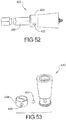
- the floating sleeve 510 includes an elongated annular recess 512 on an outer surface thereof and a pair of tapered window openings 514 extending through the sleeve 510 opposite one another within the elongated annular recess 512.
- the window openings 514 each receive a ball 516 therein and a spring band 518 is received within the elongated annular recess 512 over top of the balls 516 to secure the balls 516 within the tapered window openings 514.
- the balls 516 are designed to be received in a reduced diameter portion 306 of the tool bit 300 between the forward and rearward shoulders 308, 310 to limit the axial movement of the floating sleeve 510 in the forward and rearward directions.
- first and second shank portions 924, 926 Adjacent the first and second working portions 904, 908 are first and second shank portions 924, 926, each of which is disposed between the respective working portion 904, 908 and reduced diameter portion 912, 914.
- the shank portions 924, 926 each have a hex-shaped cross-section and are interrupted by an annular groove 928, 930.
- the first shank portion 924 is configured to be retained in a tool holder of a fastening tool when the second working region 908 is being used to drive a fastener.
- the second shank portion 926 is configured to be retained in a tool holder of a fastening tool when the first working region 904 is being used to drive a fastener.
- Disposed between the reduced diameter portions 912, 914 is an intermediate portion 932 also having a hex-shaped cross-section.
- first and second shank portions 924", 926 Adjacent the first and second working portions 904", 908" are first and second shank portions 924", 926", each of which is disposed between the respective working portion 904", 908" and reduced diameter portion 912", 914".
- the shank portions 924", 926" each have a hex-shaped cross-section and are interrupted by an annular groove 928", 930".
- the first shank portion 924" is configured to be retained in a tool holder of a fastening tool when the second working region 908" is being used to drive a fastener.
- the second shank portion 926" is configured to be retained in a tool holder of a fastening tool when the first working region 904" is being used to drive a fastener.
Landscapes
- Engineering & Computer Science (AREA)
- Mechanical Engineering (AREA)
- Details Of Spanners, Wrenches, And Screw Drivers And Accessories (AREA)
Applications Claiming Priority (4)
| Application Number | Priority Date | Filing Date | Title |
|---|---|---|---|
| CN201420463546.6U CN204397783U (zh) | 2013-08-15 | 2014-08-15 | 刀头组件、刀头夹组件和用于旋转工具的刀头夹组件 |
| TW103214649U TWM500658U (zh) | 2013-08-15 | 2014-08-15 | 刀頭組件和具有磁浮套筒的刀頭夾組件 |
| US14/817,323 US9943946B2 (en) | 2012-02-15 | 2015-08-04 | Tool bits with floating magnet sleeves |
| EP15180953.0A EP3009234B1 (de) | 2014-08-15 | 2015-08-13 | Werkzeugteile mit beweglichen magnethülsen |
Related Parent Applications (2)
| Application Number | Title | Priority Date | Filing Date |
|---|---|---|---|
| EP15180953.0A Division-Into EP3009234B1 (de) | 2014-08-15 | 2015-08-13 | Werkzeugteile mit beweglichen magnethülsen |
| EP15180953.0A Division EP3009234B1 (de) | 2014-08-15 | 2015-08-13 | Werkzeugteile mit beweglichen magnethülsen |
Publications (1)
| Publication Number | Publication Date |
|---|---|
| EP3760378A1 true EP3760378A1 (de) | 2021-01-06 |
Family
ID=53969167
Family Applications (2)
| Application Number | Title | Priority Date | Filing Date |
|---|---|---|---|
| EP15180953.0A Active EP3009234B1 (de) | 2014-08-15 | 2015-08-13 | Werkzeugteile mit beweglichen magnethülsen |
| EP20190507.2A Withdrawn EP3760378A1 (de) | 2014-08-15 | 2015-08-13 | Werkzeugeinsatz mit torsionszonen mit reduziertem durchmesser |
Family Applications Before (1)
| Application Number | Title | Priority Date | Filing Date |
|---|---|---|---|
| EP15180953.0A Active EP3009234B1 (de) | 2014-08-15 | 2015-08-13 | Werkzeugteile mit beweglichen magnethülsen |
Country Status (1)
| Country | Link |
|---|---|
| EP (2) | EP3009234B1 (de) |
Families Citing this family (3)
| Publication number | Priority date | Publication date | Assignee | Title |
|---|---|---|---|---|
| EP3235596B1 (de) * | 2016-04-21 | 2020-10-28 | Chang, Chia-Feng | Schraubendrehereinsatzanordnung mit einer magnetischen struktur |
| CN108237498B (zh) * | 2016-12-27 | 2024-04-09 | 苏州宝时得电动工具有限公司 | 夹头 |
| DE102021122932B3 (de) | 2021-09-06 | 2022-08-11 | Kirchhoff Witte Gmbh | Bithalter zum Halten und Eindrehen einer Schraube mit einem Schraubenkopf in einen Befestigungsgrund |
Citations (11)
| Publication number | Priority date | Publication date | Assignee | Title |
|---|---|---|---|---|
| WO1995020470A1 (en) * | 1994-01-26 | 1995-08-03 | Vermont American Corporation | Insert bit for use with a powered screwdriver |
| US5704261A (en) | 1992-12-22 | 1998-01-06 | Wera Werk Hermann Werner Gmbh & Co. | Torque-transmitting tool |
| US5988957A (en) | 1998-12-21 | 1999-11-23 | Black & Decker Inc. | Quick clamp |
| US6261035B1 (en) | 1998-11-12 | 2001-07-17 | Black & Decker Inc. | Chuck, bit, assembly thereof and methods of mounting |
| US6929266B2 (en) | 2002-06-18 | 2005-08-16 | Black & Decker Inc. | Bit holder |
| US7086813B1 (en) | 1998-06-26 | 2006-08-08 | Black & Decker Inc. | Quick-acting tool bit holder |
| US7942426B2 (en) | 2006-07-12 | 2011-05-17 | Black & Decker Inc. | Pivotal/rigid accessories for power and hand tools |
| WO2012049078A1 (de) * | 2010-10-15 | 2012-04-19 | Wera - Werk Hermann Werner Gmbh & Co. Kg | Drehmomentübertragungsvorrichtung zur verwendung mit einem drehschlagschrauber |
| US20120126497A1 (en) | 2010-11-23 | 2012-05-24 | Ying-Mo Lin | Small outer diameter quick release extension rod |
| WO2013031339A1 (ja) * | 2011-08-30 | 2013-03-07 | 株式会社ベッセル工業 | ドライバービット |
| EP2628570A2 (de) * | 2012-02-15 | 2013-08-21 | Black & Decker Inc. | Schnellwechsel-Bithalter mit Ringmagnet |
Family Cites Families (3)
| Publication number | Priority date | Publication date | Assignee | Title |
|---|---|---|---|---|
| DE10148943B4 (de) * | 2001-05-17 | 2004-02-26 | Felo-Werkzeugfabrik Holland-Letz Gmbh | Schraubvorrichtung für Schraubendreher-Einsätze |
| US9227309B2 (en) * | 2012-02-15 | 2016-01-05 | Black & Decker Inc. | Quick change bit holder with ring magnet |
| DE202013008907U1 (de) * | 2013-10-07 | 2014-01-21 | Chung-Yen Ho | Kombinationsbuchse- und Schraubendreher-Aufbau |
-
2015
- 2015-08-13 EP EP15180953.0A patent/EP3009234B1/de active Active
- 2015-08-13 EP EP20190507.2A patent/EP3760378A1/de not_active Withdrawn
Patent Citations (11)
| Publication number | Priority date | Publication date | Assignee | Title |
|---|---|---|---|---|
| US5704261A (en) | 1992-12-22 | 1998-01-06 | Wera Werk Hermann Werner Gmbh & Co. | Torque-transmitting tool |
| WO1995020470A1 (en) * | 1994-01-26 | 1995-08-03 | Vermont American Corporation | Insert bit for use with a powered screwdriver |
| US7086813B1 (en) | 1998-06-26 | 2006-08-08 | Black & Decker Inc. | Quick-acting tool bit holder |
| US6261035B1 (en) | 1998-11-12 | 2001-07-17 | Black & Decker Inc. | Chuck, bit, assembly thereof and methods of mounting |
| US5988957A (en) | 1998-12-21 | 1999-11-23 | Black & Decker Inc. | Quick clamp |
| US6929266B2 (en) | 2002-06-18 | 2005-08-16 | Black & Decker Inc. | Bit holder |
| US7942426B2 (en) | 2006-07-12 | 2011-05-17 | Black & Decker Inc. | Pivotal/rigid accessories for power and hand tools |
| WO2012049078A1 (de) * | 2010-10-15 | 2012-04-19 | Wera - Werk Hermann Werner Gmbh & Co. Kg | Drehmomentübertragungsvorrichtung zur verwendung mit einem drehschlagschrauber |
| US20120126497A1 (en) | 2010-11-23 | 2012-05-24 | Ying-Mo Lin | Small outer diameter quick release extension rod |
| WO2013031339A1 (ja) * | 2011-08-30 | 2013-03-07 | 株式会社ベッセル工業 | ドライバービット |
| EP2628570A2 (de) * | 2012-02-15 | 2013-08-21 | Black & Decker Inc. | Schnellwechsel-Bithalter mit Ringmagnet |
Also Published As
| Publication number | Publication date |
|---|---|
| EP3009234A1 (de) | 2016-04-20 |
| EP3009234B1 (de) | 2020-09-23 |
Similar Documents
| Publication | Publication Date | Title |
|---|---|---|
| US10556329B2 (en) | Tool bits with floating magnet sleeves | |
| US9505108B2 (en) | Bit holder with floating magnet sleeve | |
| US9227309B2 (en) | Quick change bit holder with ring magnet | |
| US10040179B2 (en) | Fastener tool assemblies | |
| EP2837468B1 (de) | Bithalter mit beweglicher Magnethülse | |
| US10150205B2 (en) | Fastening tools with floating magnet sleeves | |
| EP1637285B1 (de) | Bohrerspitzenhaltervorrichtung | |
| US7086813B1 (en) | Quick-acting tool bit holder | |
| US8622401B2 (en) | Bit retention device | |
| US7160065B2 (en) | Chuck with quick change | |
| US7726664B2 (en) | Universal tool bit shank | |
| US20090174157A1 (en) | Tool connecting device | |
| US20090139378A1 (en) | Driver tool having adjustable structure | |
| US20150102567A1 (en) | Tool joint | |
| US20060254394A1 (en) | Fastener driver | |
| EP3009234B1 (de) | Werkzeugteile mit beweglichen magnethülsen | |
| GB2441023A (en) | Locking chuck | |
| WO2001066287A2 (en) | Rotary tool holder | |
| EP3162506A1 (de) | Befestigungswerkzeuge mit beweglichen magnethülsen | |
| US11440167B2 (en) | Anti-marring bit holder | |
| US20240123582A1 (en) | Double-ended quick-change tool bit holder assembly and quick-change bit driver modification |
Legal Events
| Date | Code | Title | Description |
|---|---|---|---|
| PUAI | Public reference made under article 153(3) epc to a published international application that has entered the european phase |
Free format text: ORIGINAL CODE: 0009012 |
|
| STAA | Information on the status of an ep patent application or granted ep patent |
Free format text: STATUS: THE APPLICATION HAS BEEN PUBLISHED |
|
| AC | Divisional application: reference to earlier application |
Ref document number: 3009234 Country of ref document: EP Kind code of ref document: P |
|
| AK | Designated contracting states |
Kind code of ref document: A1 Designated state(s): AL AT BE BG CH CY CZ DE DK EE ES FI FR GB GR HR HU IE IS IT LI LT LU LV MC MK MT NL NO PL PT RO RS SE SI SK SM TR |
|
| RIN1 | Information on inventor provided before grant (corrected) |
Inventor name: JIANG, DENNY Inventor name: BRUNSON, MARK E Inventor name: HUANG, MICHAEL Inventor name: MITCHENER-KEFFER, RUTH E. Inventor name: MOSS, DARREN B. Inventor name: LEE, DAVID B. Inventor name: PETERS, MICHAEL P. Inventor name: SANTAMARINA, ALAND |
|
| STAA | Information on the status of an ep patent application or granted ep patent |
Free format text: STATUS: THE APPLICATION IS DEEMED TO BE WITHDRAWN |
|
| 18D | Application deemed to be withdrawn |
Effective date: 20210707 |