EP3759328B1 - Verdichteranordnung für eine brennkraftmaschine sowie verfahren zum betreiben einer verdichteranordnung - Google Patents
Verdichteranordnung für eine brennkraftmaschine sowie verfahren zum betreiben einer verdichteranordnung Download PDFInfo
- Publication number
- EP3759328B1 EP3759328B1 EP19702389.8A EP19702389A EP3759328B1 EP 3759328 B1 EP3759328 B1 EP 3759328B1 EP 19702389 A EP19702389 A EP 19702389A EP 3759328 B1 EP3759328 B1 EP 3759328B1
- Authority
- EP
- European Patent Office
- Prior art keywords
- propellant
- port
- compressor
- connection
- housing
- Prior art date
- Legal status (The legal status is an assumption and is not a legal conclusion. Google has not performed a legal analysis and makes no representation as to the accuracy of the status listed.)
- Active
Links
Images


Classifications
-
- F—MECHANICAL ENGINEERING; LIGHTING; HEATING; WEAPONS; BLASTING
- F02—COMBUSTION ENGINES; HOT-GAS OR COMBUSTION-PRODUCT ENGINE PLANTS
- F02B—INTERNAL-COMBUSTION PISTON ENGINES; COMBUSTION ENGINES IN GENERAL
- F02B37/00—Engines characterised by provision of pumps driven at least for part of the time by exhaust
-
- F—MECHANICAL ENGINEERING; LIGHTING; HEATING; WEAPONS; BLASTING
- F01—MACHINES OR ENGINES IN GENERAL; ENGINE PLANTS IN GENERAL; STEAM ENGINES
- F01M—LUBRICATING OF MACHINES OR ENGINES IN GENERAL; LUBRICATING INTERNAL COMBUSTION ENGINES; CRANKCASE VENTILATING
- F01M13/00—Crankcase ventilating or breathing
- F01M13/02—Crankcase ventilating or breathing by means of additional source of positive or negative pressure
- F01M13/021—Crankcase ventilating or breathing by means of additional source of positive or negative pressure of negative pressure
-
- F—MECHANICAL ENGINEERING; LIGHTING; HEATING; WEAPONS; BLASTING
- F02—COMBUSTION ENGINES; HOT-GAS OR COMBUSTION-PRODUCT ENGINE PLANTS
- F02B—INTERNAL-COMBUSTION PISTON ENGINES; COMBUSTION ENGINES IN GENERAL
- F02B37/00—Engines characterised by provision of pumps driven at least for part of the time by exhaust
- F02B37/12—Control of the pumps
- F02B37/16—Control of the pumps by bypassing charging air
-
- F—MECHANICAL ENGINEERING; LIGHTING; HEATING; WEAPONS; BLASTING
- F02—COMBUSTION ENGINES; HOT-GAS OR COMBUSTION-PRODUCT ENGINE PLANTS
- F02B—INTERNAL-COMBUSTION PISTON ENGINES; COMBUSTION ENGINES IN GENERAL
- F02B37/00—Engines characterised by provision of pumps driven at least for part of the time by exhaust
- F02B37/12—Control of the pumps
- F02B37/16—Control of the pumps by bypassing charging air
- F02B37/164—Control of the pumps by bypassing charging air the bypassed air being used in an auxiliary apparatus, e.g. in an air turbine
-
- F—MECHANICAL ENGINEERING; LIGHTING; HEATING; WEAPONS; BLASTING
- F02—COMBUSTION ENGINES; HOT-GAS OR COMBUSTION-PRODUCT ENGINE PLANTS
- F02B—INTERNAL-COMBUSTION PISTON ENGINES; COMBUSTION ENGINES IN GENERAL
- F02B39/00—Component parts, details, or accessories relating to, driven charging or scavenging pumps, not provided for in groups F02B33/00 - F02B37/00
- F02B39/16—Other safety measures for, or other control of, pumps
-
- F—MECHANICAL ENGINEERING; LIGHTING; HEATING; WEAPONS; BLASTING
- F02—COMBUSTION ENGINES; HOT-GAS OR COMBUSTION-PRODUCT ENGINE PLANTS
- F02M—SUPPLYING COMBUSTION ENGINES IN GENERAL WITH COMBUSTIBLE MIXTURES OR CONSTITUENTS THEREOF
- F02M25/00—Engine-pertinent apparatus for adding non-fuel substances or small quantities of secondary fuel to combustion-air, main fuel or fuel-air mixture
- F02M25/08—Engine-pertinent apparatus for adding non-fuel substances or small quantities of secondary fuel to combustion-air, main fuel or fuel-air mixture adding fuel vapours drawn from engine fuel reservoir
- F02M25/0809—Judging failure of purge control system
-
- F—MECHANICAL ENGINEERING; LIGHTING; HEATING; WEAPONS; BLASTING
- F02—COMBUSTION ENGINES; HOT-GAS OR COMBUSTION-PRODUCT ENGINE PLANTS
- F02M—SUPPLYING COMBUSTION ENGINES IN GENERAL WITH COMBUSTIBLE MIXTURES OR CONSTITUENTS THEREOF
- F02M25/00—Engine-pertinent apparatus for adding non-fuel substances or small quantities of secondary fuel to combustion-air, main fuel or fuel-air mixture
- F02M25/08—Engine-pertinent apparatus for adding non-fuel substances or small quantities of secondary fuel to combustion-air, main fuel or fuel-air mixture adding fuel vapours drawn from engine fuel reservoir
- F02M25/0872—Details of the fuel vapour pipes or conduits
-
- F—MECHANICAL ENGINEERING; LIGHTING; HEATING; WEAPONS; BLASTING
- F02—COMBUSTION ENGINES; HOT-GAS OR COMBUSTION-PRODUCT ENGINE PLANTS
- F02M—SUPPLYING COMBUSTION ENGINES IN GENERAL WITH COMBUSTIBLE MIXTURES OR CONSTITUENTS THEREOF
- F02M35/00—Combustion-air cleaners, air intakes, intake silencers, or induction systems specially adapted for, or arranged on, internal-combustion engines
- F02M35/02—Air cleaners
- F02M35/08—Air cleaners with means for removing dust, particles or liquids from cleaners; with means for indicating clogging; with by-pass means; Regeneration of cleaners
- F02M35/086—Dust removal by flushing, blasting, pulsating or aspirating flow, washing or the like; Mechanical dust removal, e.g. by using scrapers
-
- F—MECHANICAL ENGINEERING; LIGHTING; HEATING; WEAPONS; BLASTING
- F02—COMBUSTION ENGINES; HOT-GAS OR COMBUSTION-PRODUCT ENGINE PLANTS
- F02M—SUPPLYING COMBUSTION ENGINES IN GENERAL WITH COMBUSTIBLE MIXTURES OR CONSTITUENTS THEREOF
- F02M35/00—Combustion-air cleaners, air intakes, intake silencers, or induction systems specially adapted for, or arranged on, internal-combustion engines
- F02M35/10—Air intakes; Induction systems
- F02M35/10091—Air intakes; Induction systems characterised by details of intake ducts: shapes; connections; arrangements
- F02M35/10118—Air intakes; Induction systems characterised by details of intake ducts: shapes; connections; arrangements with variable cross-sections of intake ducts along their length; Venturis; Diffusers
-
- F—MECHANICAL ENGINEERING; LIGHTING; HEATING; WEAPONS; BLASTING
- F02—COMBUSTION ENGINES; HOT-GAS OR COMBUSTION-PRODUCT ENGINE PLANTS
- F02M—SUPPLYING COMBUSTION ENGINES IN GENERAL WITH COMBUSTIBLE MIXTURES OR CONSTITUENTS THEREOF
- F02M35/00—Combustion-air cleaners, air intakes, intake silencers, or induction systems specially adapted for, or arranged on, internal-combustion engines
- F02M35/10—Air intakes; Induction systems
- F02M35/1015—Air intakes; Induction systems characterised by the engine type
- F02M35/10157—Supercharged engines
-
- F—MECHANICAL ENGINEERING; LIGHTING; HEATING; WEAPONS; BLASTING
- F02—COMBUSTION ENGINES; HOT-GAS OR COMBUSTION-PRODUCT ENGINE PLANTS
- F02M—SUPPLYING COMBUSTION ENGINES IN GENERAL WITH COMBUSTIBLE MIXTURES OR CONSTITUENTS THEREOF
- F02M35/00—Combustion-air cleaners, air intakes, intake silencers, or induction systems specially adapted for, or arranged on, internal-combustion engines
- F02M35/10—Air intakes; Induction systems
- F02M35/10209—Fluid connections to the air intake system; their arrangement of pipes, valves or the like
- F02M35/10222—Exhaust gas recirculation [EGR]; Positive crankcase ventilation [PCV]; Additional air admission, lubricant or fuel vapour admission
-
- F—MECHANICAL ENGINEERING; LIGHTING; HEATING; WEAPONS; BLASTING
- F02—COMBUSTION ENGINES; HOT-GAS OR COMBUSTION-PRODUCT ENGINE PLANTS
- F02M—SUPPLYING COMBUSTION ENGINES IN GENERAL WITH COMBUSTIBLE MIXTURES OR CONSTITUENTS THEREOF
- F02M35/00—Combustion-air cleaners, air intakes, intake silencers, or induction systems specially adapted for, or arranged on, internal-combustion engines
- F02M35/10—Air intakes; Induction systems
- F02M35/10209—Fluid connections to the air intake system; their arrangement of pipes, valves or the like
- F02M35/10229—Fluid connections to the air intake system; their arrangement of pipes, valves or the like the intake system acting as a vacuum or overpressure source for auxiliary devices, e.g. brake systems; Vacuum chambers
-
- F—MECHANICAL ENGINEERING; LIGHTING; HEATING; WEAPONS; BLASTING
- F04—POSITIVE - DISPLACEMENT MACHINES FOR LIQUIDS; PUMPS FOR LIQUIDS OR ELASTIC FLUIDS
- F04F—PUMPING OF FLUID BY DIRECT CONTACT OF ANOTHER FLUID OR BY USING INERTIA OF FLUID TO BE PUMPED; SIPHONS
- F04F5/00—Jet pumps, i.e. devices in which flow is induced by pressure drop caused by velocity of another fluid flow
- F04F5/14—Jet pumps, i.e. devices in which flow is induced by pressure drop caused by velocity of another fluid flow the inducing fluid being elastic fluid
- F04F5/16—Jet pumps, i.e. devices in which flow is induced by pressure drop caused by velocity of another fluid flow the inducing fluid being elastic fluid displacing elastic fluids
- F04F5/20—Jet pumps, i.e. devices in which flow is induced by pressure drop caused by velocity of another fluid flow the inducing fluid being elastic fluid displacing elastic fluids for evacuating
-
- F—MECHANICAL ENGINEERING; LIGHTING; HEATING; WEAPONS; BLASTING
- F01—MACHINES OR ENGINES IN GENERAL; ENGINE PLANTS IN GENERAL; STEAM ENGINES
- F01M—LUBRICATING OF MACHINES OR ENGINES IN GENERAL; LUBRICATING INTERNAL COMBUSTION ENGINES; CRANKCASE VENTILATING
- F01M13/00—Crankcase ventilating or breathing
- F01M13/02—Crankcase ventilating or breathing by means of additional source of positive or negative pressure
- F01M13/021—Crankcase ventilating or breathing by means of additional source of positive or negative pressure of negative pressure
- F01M2013/027—Crankcase ventilating or breathing by means of additional source of positive or negative pressure of negative pressure with a turbo charger or compressor
-
- F—MECHANICAL ENGINEERING; LIGHTING; HEATING; WEAPONS; BLASTING
- F05—INDEXING SCHEMES RELATING TO ENGINES OR PUMPS IN VARIOUS SUBCLASSES OF CLASSES F01-F04
- F05D—INDEXING SCHEME FOR ASPECTS RELATING TO NON-POSITIVE-DISPLACEMENT MACHINES OR ENGINES, GAS-TURBINES OR JET-PROPULSION PLANTS
- F05D2220/00—Application
- F05D2220/40—Application in turbochargers
-
- F—MECHANICAL ENGINEERING; LIGHTING; HEATING; WEAPONS; BLASTING
- F05—INDEXING SCHEMES RELATING TO ENGINES OR PUMPS IN VARIOUS SUBCLASSES OF CLASSES F01-F04
- F05D—INDEXING SCHEME FOR ASPECTS RELATING TO NON-POSITIVE-DISPLACEMENT MACHINES OR ENGINES, GAS-TURBINES OR JET-PROPULSION PLANTS
- F05D2260/00—Function
- F05D2260/60—Fluid transfer
- F05D2260/601—Fluid transfer using an ejector or a jet pump
-
- Y—GENERAL TAGGING OF NEW TECHNOLOGICAL DEVELOPMENTS; GENERAL TAGGING OF CROSS-SECTIONAL TECHNOLOGIES SPANNING OVER SEVERAL SECTIONS OF THE IPC; TECHNICAL SUBJECTS COVERED BY FORMER USPC CROSS-REFERENCE ART COLLECTIONS [XRACs] AND DIGESTS
- Y02—TECHNOLOGIES OR APPLICATIONS FOR MITIGATION OR ADAPTATION AGAINST CLIMATE CHANGE
- Y02T—CLIMATE CHANGE MITIGATION TECHNOLOGIES RELATED TO TRANSPORTATION
- Y02T10/00—Road transport of goods or passengers
- Y02T10/10—Internal combustion engine [ICE] based vehicles
- Y02T10/12—Improving ICE efficiencies
Definitions
- the invention relates to a compressor arrangement for an internal combustion engine, with a compressor which is arranged in a compressor housing and has a low-pressure side and a high-pressure side, and with a vacuum supply device which, in terms of flow, on the one hand via a propellant inlet connection to the high-pressure side of the compressor and on the other hand via a propellant outlet connection to the low-pressure side of the compressor connected propellant channel with a nozzle and a vacuum channel that opens out into the propellant channel in terms of flow between the propellant inlet port and the propellant outlet port, the propellant channel being formed in a housing separate from the compressor housing, on which the propellant inlet port and the propellant outlet port are formed, the propellant inlet port having a first port and the propellant outlet port with a second port i n fluidic connection can be brought.
- the invention also relates to a method for operating a compressor arrangement.
- a first and a second aspirator each comprising a suction bleed in a throat of the aspirator, a suction bleed in a flare cone of the aspirator, and a suction bleed in a straight tube, downstream of the flare cone, wherein the first aspirator connected to an engine intake power inlet and a mixture flow outlet connected to the intake downstream of a main throttle, and wherein the second aspirator comprises a mixture flow outlet connected to the intake downstream of the power inlet of the first aspirator and a power inlet connected to the intake downstream of the main throttle.
- venturi module for a compressor housing for use with a tank ventilation system with a first opening for coupling to a first channel section of a connecting channel from a high-pressure area to a low-pressure area of a compressor housing, a second opening for coupling to a second channel section of the connecting channel, a passage between the first Opening and the second opening inside the venturi module in the form of a venturi nozzle and a pickup tube in the form of a connecting piece for coupling the venturi module to a tank ventilation system.
- the venturi module is designed as an integral component and also has a flange for fastening the venturi module to a compressor housing.
- a compressor housing for a compressor of a turbocharger is also described, with a low-pressure area, a high-pressure area, and a connecting duct from the low-pressure area to the high-pressure area, the connecting duct having a recess open to the environment for accommodating a Venturi module.
- the pamphlet JP 2015-187438 A describes a device for removing fuel vapor from a fuel tank.
- a discharge device is integrated into an inlet connection of a compressor, the discharge device extracting part of the charge air downstream of the compressor via a flow connection and the fuel vapor being fed from the fuel tank to the compressor.
- the first connection and the second connection are formed on a flow guidance element connected to the compressor housing, and that only the propellant outlet connection is formed as a plug-in connection, the propellant outlet connection having a plug-in connection projection and the second connection having a plug-in connection receptacle for receiving the plug-in connection projection, wherein the propellant inlet connection and the first connection each have a passage opening extending through a contact surface, so that a flow connection can be produced between the propellant inlet connection and the first connection by the contact surfaces lying flat against one another.
- the propellant channel is formed in a housing that is separate from the compressor housing and on which the propellant inlet connection and the propellant outlet connection are formed.
- the compressor arrangement can be assigned to the internal combustion engine and in this respect can be a component of the internal combustion engine. It preferably serves to provide compressed fresh gas for the internal combustion engine.
- the compressor arrangement has the compressor, which is provided with fresh gas at a first pressure on the low-pressure side.
- the compressor compresses the fresh gas that is provided and in turn makes it available on the high-pressure side for the internal combustion engine, namely at a second pressure that is higher than the first pressure.
- the fresh gas can be present in the form of fresh air, but also as a fresh air/exhaust gas mixture.
- the internal combustion engine is, for example, connected to an external one Equipped with exhaust gas recirculation.
- the compressor or the compressor arrangement can be part of an exhaust gas turbocharger, for example, which is assigned to the internal combustion engine.
- the compressor arrangement has the vacuum supply device, by means of which vacuum can be provided or is provided for a vacuum consumer.
- the vacuum consumer is present, for example, in the form of a flushing device for a filter, in particular for an activated carbon filter, and/or as a ventilation device, in particular as a crankcase ventilation device.
- the vacuum supply device has the propellant channel, through which a propellant can be guided to provide the vacuum.
- the fresh gas compressed by the compressor is used as the propellant for providing the vacuum.
- the propellant channel is fluidically connected on the one hand to the high-pressure side of the compressor and on the other hand to the low-pressure side of the compressor.
- the vacuum supply device has the propellant inlet connection for connecting the propellant channel to the high-pressure side and the propellant outlet connection for connection to the low-pressure side.
- the vacuum supply device in particular the propellant channel, represents a bypass for the compressor, via which fresh gas that has already been compressed can be routed or is routed back from the high-pressure side to the low-pressure side.
- the vacuum channel opens into the propellant channel.
- the vacuum is provided when propellant or fresh gas flows through the propellant channel.
- the nozzle is arranged in the propellant channel to provide the negative pressure.
- the propellant inlet port is flow-connected to the propellant outlet port via the nozzle.
- the vacuum channel opens, for example, into the nozzle or downstream of the nozzle, in particular directly downstream of the nozzle, into the propellant channel.
- the nozzle is in the form of a Venturi nozzle, in which the Venturi effect is utilized in order to provide the vacuum in the vacuum channel and therefore at the vacuum connection due to the propellant flowing through the propellant channel.
- the nozzle represents a reduction in cross section into which the propellant channel opens.
- a continuous cross-section reduction down to a smallest flow cross-section is particularly preferred, which is followed by a continuous increase in the flow cross-section, ie a reduction in the cross-section reduction.
- the propellant channel preferably opens into the nozzle in the area of the smallest flow cross section, but at least in the area of the reduction in cross section.
- the nozzle is in the form of a propellant jet nozzle of a jet pump or propellant jet pump.
- the propulsion jet nozzle opens into a mixing chamber, which has a larger flow cross section than an outlet opening of the nozzle, via which the nozzle is connected to the mixing chamber.
- the negative pressure channel also opens into the mixing chamber, so that when propellant flows through the propellant channel, the fluid present in the negative pressure channel is entrained by the propellant in the direction of the propellant outlet connection, in particular by impulse input.
- the propellant channel and thus the nozzle are arranged in the housing, which is present or is formed separately from the compressor housing.
- the housing, which is part of the Vacuum supply device is mountable on the compressor housing. Before the compressor arrangement is operated, the housing of the vacuum supply device must be arranged in such a way that the propellant channel is flow-connected to the high-pressure side on the one hand and to the low-pressure side on the other hand—if the provision of negative pressure is desired.
- Forming the propellant channel in the separate housing which can be formed in one piece or in multiple parts, has the advantage that the vacuum supply device can be easily replaced.
- the vacuum supply device can be mounted particularly efficiently, in particular if the vacuum supply device is formed entirely in the housing.
- the nozzle and the negative pressure channel are formed in the housing.
- At least one area of the propellant channel, in which the nozzle is arranged, as well as the vacuum channel, is arranged in a part of the housing that is designed in one piece and/or made of the same material.
- both the area of the propellant channel and the nozzle and the vacuum channel are represented by a recess in the housing.
- the housing part can particularly preferably be present as an injection molded component, so that the area of the propellant channel, the nozzle and the vacuum channel are formed during a joint injection molding process.
- Both the propellant inlet connection and the propellant outlet connection are formed on the housing.
- One of the two connections namely the propellant outlet connection, is designed as a plug-in connection, by means of which a flow connection can be established by plugging it in.
- the plug connector enables a flow connection to be established with a high degree of tightness, which is also extremely tolerant of displacements, in particular of the vacuum supply device with respect to the compressor housing.
- the configuration of the compressor arrangement described, in particular the vacuum supply device and the housing, enables simple assembly with excellent tightness at the same time.
- To establish the flow connection of the connection designed as a plug-in connection it is only necessary to plug two elements into one another.
- the compressor arrangement enables good diagnostics, because the functionality, in particular the tightness, of the vacuum supply device can be diagnosed using a pressure sensor, which measures the pressure in the compressor arrangement, for example in the vacuum channel, at the vacuum connection or on the high-pressure side of the compressor.
- a pressure sensor is usually present in each case in order to determine the pressure of the fresh gas, which can then also be referred to as charge air.
- the vacuum supply device can have a further pressure sensor, by means of which the pressure in the vacuum channel is determined.
- a further pressure sensor by means of which the pressure in the vacuum channel is determined.
- only the pressure sensor of the compressor, which is usually present anyway, and/or the further pressure sensor assigned to the vacuum channel are necessary for a complete diagnosis or leak test of the vacuum supply device.
- a high level of operational reliability is also achieved with the aid of the compressor arrangement described.
- the invention provides that the propellant inlet port can be fluidically connected to a first port and the propellant outlet port to a second port, the first port and the second port being formed on the compressor housing or on a flow guidance element connected to the compressor housing.
- propellant can be supplied via the first connection to the vacuum supply device or the propellant channel and removed via the second connection.
- the propellant channel is connected to the high-pressure side of the first connection Compressor and fluidly connected via the second connection to the low-pressure side of the compressor or at least connectable.
- the two connections ie the first connection and the second connection, can each be present on the compressor housing. Alternatively, they are formed on the flow guidance element.
- the vacuum supply device or its housing is arranged directly on the compressor housing, namely in such a way that the propellant inlet connection is in flow connection with the first connection and the propellant outlet connection with the second connection.
- the flow guidance element is fluidically connected to the compressor, namely in such a way that the first connection is subsequently in flow connection with the high-pressure side and the second connection with the low-pressure side of the compressor.
- the flow guidance element can additionally have a fresh gas inlet duct, via which fresh gas can be supplied to the compressor.
- the fresh gas inlet duct is connected on the one hand to the low-pressure side of the compressor and on the other hand to an external environment of the internal combustion engine, in particular via a filter or air filter.
- the flow guidance element is designed or manufactured separately from the compressor housing and is arranged and fastened to it after it has been manufactured.
- the flow guidance element can be made of the same material as the compressor housing and can consist of the same material.
- the flow guidance element is particularly preferably made of a material which is different from a material of the compressor housing.
- the flow guidance element consists of a plastic, whereas the compressor housing consists of metal.
- the propellant outlet connection has a plug-in connection projection and the second connection has a plug-in connection receptacle for accommodating the plug-in connection projection.
- the plug connection projection is present on the housing of the vacuum supply device, in particular it is made of the same material and/or in one piece with it.
- the connector projection is preferably formed together with the propellant channel, the nozzle and the vacuum channel during the above-mentioned injection molding process.
- the second port has the plug-in connection receptacle, which is designed in such a way that after the plug-in connection projection has been correctly arranged in the plug-in connection receptacle, the flow connection between the propellant outlet port and the second port and thus between the propellant channel and the low-pressure side of the compressor is established.
- the plug-in connection receptacle which is designed in such a way that after the plug-in connection projection has been correctly arranged in the plug-in connection receptacle, the flow connection between the propellant outlet port and the second port and thus between the propellant channel and the low-pressure side of the compressor is established.
- the invention provides that the propellant inlet connection and the first connection each have a passage opening extending through a contact surface, so that a flow connection can be established between the propellant inlet connection and the first connection by the contact surfaces lying flat against one another.
- the passage opening of the propellant inlet connection reaches through a contact surface formed on the housing of the vacuum supply device, and the passage opening of the first connection penetrates a contact surface formed on the compressor housing or the flow guidance element.
- the contact surfaces are preferably each completely flat.
- the passage openings are particularly preferably each formed with a closed edge in the corresponding contact surface, ie they have a continuous edge in the circumferential direction.
- the flow connection between the propellant inlet connection and the first connection should be able to be produced by the contact surfaces lying flat against one another.
- the contact surfaces are preferably pressed tightly against one another and/or sealed against one another by means of a seal.
- the flow connection formed by the planar contact of the contact surfaces against one another has a comparatively small tolerance to displacements, in particular in comparison to the flow connection established by means of the plug-in connection. If the housing detaches from the compressor housing, in particular if it detaches unintentionally, a leak initially occurs on the side of the propellant inlet connection. The flow connection present on the side of the propellant outlet connection can only become leaky if there is a further displacement.
- the interruption of the flow connection between the propellant inlet connection and the first connection can already be diagnosed with the aid of the pressure sensor already described or the further pressure sensor, so that an error can be detected in good time and this can be displayed.
- This prevents the fluid sucked in by the vacuum supply device via the propellant channel from being able to escape from the compressor arrangement. Rather, this is still reliably supplied to the compressor via the propellant outlet connection when the flow connection between the propellant inlet connection and the first connection is already interrupted or leaking.
- the already mentioned excellent ability to diagnose the vacuum supply device has been implemented.
- a preferred further embodiment of the invention provides that the propellant inlet connection has an axial ring seal that interacts with the first connection, and the propellant outlet connection has a radial ring seal that interacts with the second connection.
- the axial ring seal completely surrounds the propellant inlet connection in the circumferential direction and, after assembly, also the first connection.
- the axial ring seal is to be understood as a ring seal in which the sealing effect is achieved by axial elastic compression.
- the radial ring seal is a ring seal in which the sealing effect is brought about by elastic radial compression.
- the axial ring seal is arranged in sealing contact with the contact surfaces of the propellant inlet connection and the first connection or at least one of these contact surfaces in order to implement the sealing effect.
- the axial ring seal is arranged in a seal receptacle that extends through one of the contact surfaces and, after assembly, lies against the respective other contact surface in a sealing manner.
- seal receptacles can also be present in both contact surfaces, as long as it is ensured that the propellant inlet connection and the first connection are tightly connected to one another after assembly.
- the radial ring seal is preferably designed in such a way that it is present on the plug-in connection projection and encompasses it in the circumferential direction.
- the radial ring seal is introduced into the plug-in connection receptacle together with the plug-in connection projection and then bears sealingly against a wall delimiting the plug-in connection receptacle in the radial direction, in particular continuously in the circumferential direction.
- a seal receptacle is formed in the plug-in connection projection, in which the radial ring seal is arranged in order to realize a reliable fastening of the radial ring seal and thus to prevent the radial ring seal from being lost.
- Such a choice of seals i.e. the provision of the axial ring seal on the propellant inlet connection and the provision of the radial ring seal on the propellant outlet connection, ensures the reliable diagnosability already described above, in that the flow connection of the propellant outlet connection to the second connection is significantly more tolerant of displacements due to the radial ring seal than the Flow communication between the propellant inlet port and the first port via the axial ring seal.
- the vacuum supply device in particular the housing
- the housing is displaced with respect to the compressor housing and/or the flow guidance element, starting from a first position in which both flow connections are tight, in the direction of a second position in which both flow connections are interrupted or leaking, the Flow connection between the propellant inlet port and the first port and only later the flow connection between the propellant outlet port and the second port leaking.
- a further preferred embodiment of the invention provides that the propellant channel has a deflection within the housing, so that the propellant inlet connection and the propellant outlet connection are arranged on the same side of the housing.
- the plug-in connection projection will first engage in the plug-in connection receptacle and then the contact surfaces of the propellant inlet connection and the first connection will come into contact in a sealing manner.
- a further preferred embodiment of the invention provides that the propellant inlet connection and the propellant outlet connection are formed parallel to one another on the housing.
- a notional plane defining the propellant inlet port and a notional plane defining the propellant outlet port are parallel but spaced from each other.
- the imaginary plane coincides, for example, with the contact surface through which the passage opening extends.
- the plane preferably continuously accommodates the edge of the plug connection projection on its side furthest away from the propellant channel. Both planes are preferably perpendicular to the longitudinal center axis of the propellant channel at the propellant inlet connection and/or a longitudinal center axis of the propellant channel at the propellant outlet connection.
- the offset configuration of the propellant inlet connection and the propellant outlet connection is preferably implemented by means of the plug connection projection.
- the connector projection begins in the plane defining the propellant inlet port and extends to the plane defining the propellant outlet port. This achieves excellent tightness of the flow connection between the connections of the vacuum supply device and the connections of the compressor housing or the flow guidance element.
- a further embodiment of the invention provides that the deflection is formed by means of a cover of the housing that delimits the propellant channel in certain areas.
- the housing is designed in several parts and has a base element and the cover.
- a part of the propellant channel, in particular a large part of the propellant channel, is arranged in the base element, for example.
- the vacuum channel, at least in certain areas, and the nozzle are preferably arranged in the base element.
- the cover is detachably or non-detachably connected to the base element.
- the detachable connection takes place, for example, in a form-fitting manner, in particular by means of a snap-in connection.
- the non-detachable connection can be realized, for example, by welding.
- the use of the cover allows a simple and inexpensive configuration of the housing, for example by injection moulding, the base and the lid being manufactured separately from each other.
- the housing can be fastened by means of at least one screw, with a central longitudinal axis of a receiving opening in the housing for receiving the screw being parallel to a central longitudinal axis of the propellant channel on the propellant inlet connection and/or a central longitudinal axis of the propellant channel the propellant outlet port is arranged.
- the screw is used to fasten the housing, for example to the compressor housing or to the flow guidance element.
- the housing has the receiving opening, which is dimensioned such that a shank of the screw can be passed through it, whereas a head of the screw rests against an edge delimiting the receiving opening or the edge represents an end stop for the head.
- the receiving opening is preferably completely straight in the direction of its longitudinal central axis.
- the longitudinal center axis of the receiving opening runs parallel to the longitudinal center axis of the propellant channel on the side of the propellant inlet connection and/or on the side of the propellant outlet connection.
- the housing is fastened to the compressor housing or the flow guidance element by means of the screw in such a way that the contact surfaces of the propellant inlet connection and the first connection are pressed against one another.
- the longitudinal central axis of the receiving opening for the screw is particularly preferably perpendicular to both contact surfaces.
- the invention also relates to a method for operating a compressor arrangement for an internal combustion engine, in particular a compressor arrangement according to the statements made within the scope of this description, the compressor arrangement having a compressor which is arranged in a compressor housing and has a low-pressure side and a high-pressure side and has a vacuum supply device which has a on the one hand via a propellant inlet connection to the high-pressure side of the compressor and on the other hand via a propellant outlet connection to the low-pressure side of the compressor, fluidically connected propellant channel with a nozzle and a fluidically between the propellant inlet connection and the propellant outlet connection into the propellant channel.
- the propellant channel is formed in a housing which is separate from the compressor housing and on which the propellant inlet connection and the propellant outlet connection are formed.
- the propellant inlet connection can be brought into fluidic connection with a first connection and the propellant outlet connection with a second connection, the first connection and the second connection being formed on a flow guidance element connected to the compressor housing, and that only the propellant outlet connection is designed as a plug-in connection is, wherein the propellant outlet port has a plug-in connection projection and the second port has a plug-in connection receptacle for receiving the plug-in connection projection, wherein the propellant inlet port and the first port each have a through-opening that extends through a contact surface, so that a flow connection between the propellant inlet port and the first port is achieved by the contact surfaces lying flat against one another is made, and that by means of a pressure sensor, a pressure in the vacuum channel or on the high pressure side of the compressor and a leak is detected when the pressure falls below or exceeds a limit value.
- the pressure sensor is used, for example, to measure the pressure in the vacuum channel, at the vacuum connection or on the high-pressure side of the compressor. If the measured pressure deviates from the limit value or falls below or exceeds it, it can be assumed that there is a leak or another malfunction.
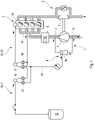
- the figure 1 shows a schematic representation of a compressor arrangement 1 for an internal combustion engine 2.
- the compressor arrangement 1 is part of an exhaust gas turbocharger 3, which has a turbine 4 and a compressor 5, the latter being part of the compressor arrangement 1.
- Exhaust gas from the internal combustion engine 2 can be supplied to the turbine 4 .
- the flow energy and/or enthalpy contained in the exhaust gas is converted into kinetic energy with the aid of the turbine 4 converted, which in turn serves to drive the compressor 5.
- the compressor 5 serves to compress fresh gas, the fresh gas being made available to the compressor 5 on a low-pressure side 6 .
- the fresh gas compressed by means of the compressor 5 is available on its high-pressure side 7 of the internal combustion engine 2 .
- a charge air cooler 8 can be provided in terms of flow between the high-pressure side 7 of the compressor 5 and the internal combustion engine 2 .
- a vacuum supply device 9 which serves to provide vacuum for at least one vacuum consumer 10, in the exemplary embodiment shown here for two vacuum consumers 10.
- One of the vacuum consumers 10 is present as a flushing device 11 for a filter 12, the filter 12 preferably being configured as an activated carbon filter.
- Another of the vacuum consumers 10 is designed as a venting device 13 which serves to vent a cylinder crankcase 14 of the internal combustion engine 2 .
- the vacuum consumer 10 or the vacuum consumers 10 are each connected via check valves 15 to an intake manifold 16 of the internal combustion engine 2 or an intake manifold.
- the vacuum consumer 10 or the vacuum consumers 10 are connected via check valves 17 to a vacuum connection 18 of the vacuum supply device 9 .
- the vacuum consumer 10 or the vacuum consumers 10 are in this respect always fluidly connected to the intake manifold 16 or the vacuum connection 18, depending on where there is a stronger vacuum.
- the figure 2 shows a schematic representation of a region of the compressor arrangement 1 in the form of an exploded view.
- the compressor 5 of the exhaust gas turbocharger 3 and a compressor housing 19 of the compressor 5 can be seen.
- a flow guide element 20 is fluidically connected to the compressor 5, in which element there is a fresh gas inlet channel.
- the low-pressure side 6 of the Compressor 5 flow-connected to an external environment of the compressor assembly 1, preferably via a filter or air filter.
- the flow guidance element 20 is fastened to the compressor housing 19, for example by means of at least one screw 21.
- the vacuum supply device 9 is in turn fastened to the flow guidance element 20, namely preferably again by means of a screw 22.
- a first connection 23 and a second connection 24 are present on the flow guidance element 20, the first connection 23 being flow-connected via the flow guidance element 20 to the high-pressure side 7 of the compressor 5 and the second connection 24 also being flow-connected to the low-pressure side 6 via the flow guidance element 20.
- the second connection 24 is fluidically connected within the flow guidance element 20 to the fresh gas inlet channel.
- the vacuum supply device 9 has a propellant inlet connection 25 (not visible here) and a propellant outlet connection 26 .
- the propellant inlet connection 25 is brought into flow connection with the first connection 23 and the propellant outlet connection 26 with the second connection 24 when the vacuum supply device 9 is installed on the flow guidance element 20 .
- Both the propellant inlet connection 25 and the propellant outlet connection 26 are present on a housing 27 of the vacuum supply device 9 .
- the propellant outlet connection 26 is designed as a plug-in connection and in this respect has a plug-in connection projection 28 which is provided and designed to be received in a plug-in connection receptacle 29 of the second connection 24 .
- the flow connection between the propellant inlet connection 25 and the first connection 23 is established by these two contact surfaces 30 and 31 lying flat against one another.
- the housing 27 is in several parts and consists of a base element 32 and a cover 33 .
- the cover 33 is preferably non-detachably connected to the base element 32, but is manufactured separately from it. In this respect, the base element 32 and the cover 33 are connected to one another only after they have been manufactured.
- the vacuum connection 18 is formed on the housing 27, in the exemplary embodiment shown here on the base element 32, to which the at least one vacuum consumer 10 can be connected via a vacuum line 34.
- the figure 3 shows a longitudinal sectional view of the vacuum supply device 9. It can be seen that there is a propellant channel 35 in the housing 27, via which the propellant inlet connection 25 and the propellant outlet connection 26 within the housing 27 are fluidically connected to one another.
- the propellant channel 35 is mostly present in the base member 32 . In some areas, however, it is delimited by the cover 33, as a result of which a deflection 36 is realized.
- the nozzle 37 is designed as a propulsion jet nozzle, which opens into a mixing chamber 38 to which the vacuum connection 18 is also fluidically connected via a vacuum channel 39 .
- the vacuum connection 18 is also fluidically connected via a vacuum channel 39 .
- the propellant inlet connection 25 has an axial ring seal 42 and the propellant outlet connection 26 has a radial ring seal 43 .
- the axial ring seal 42 is arranged in a seal receptacle 44 and the radial ring seal 43 in a seal receptacle 45 .
- the seal receptacles 44 and 45 are in the housing 27, in particular in the Basic element 32 formed. It can also be seen that the propellant inlet connection 25 and the propellant outlet connection 26 are offset parallel to one another on the housing 27 .
- the plug-in connection projection 28 protrudes beyond a plane defining the propellant inlet connection 25, namely in the axial direction with respect to a longitudinal center axis 46 of the propellant channel on the side of the propellant inlet connection 25 or a longitudinal center axis 47 of the propellant channel 35 on the side of the propellant outlet connection 26.
- a receiving opening 48 for receiving the screw 22 is also aligned with its longitudinal center axis parallel to the longitudinal center axis 46 and/or the longitudinal center axis 47 .
- the compressor arrangement 1 described has the advantage that, on the one hand, the vacuum supply device 9 has a compact design and is also interchangeable. On the other hand, a high level of operational reliability is ensured by designing the propellant outlet connection 26 as a plug-in connection, whereas the flow connection between the propellant inlet connection 25 and the first connection 23 is established by the contact surfaces 30 and 31 lying flat against one another. In this way, a particularly simple detection of a leak or leakage is possible.
Landscapes
- Engineering & Computer Science (AREA)
- Mechanical Engineering (AREA)
- General Engineering & Computer Science (AREA)
- Chemical & Material Sciences (AREA)
- Combustion & Propulsion (AREA)
- Physics & Mathematics (AREA)
- Fluid Mechanics (AREA)
- Jet Pumps And Other Pumps (AREA)
- Structures Of Non-Positive Displacement Pumps (AREA)
- Applications Or Details Of Rotary Compressors (AREA)
- Compressors, Vaccum Pumps And Other Relevant Systems (AREA)
Description
- Die Erfindung betrifft eine Verdichteranordnung für eine Brennkraftmaschine, mit einem in einem Verdichtergehäuse angeordneten, eine Niederdruckseite und eine Hochdruckseite aufweisenden Verdichter und mit einer Unterdruckbereitstellungseinrichtung, die einen einerseits über einen Treibmitteleinlassanschluss an die Hochdruckseite des Verdichters und andererseits über einen Treibmittelauslassanschluss an die Niederdruckseite des Verdichters strömungstechnisch angeschlossenen Treibmittelkanal mit einer Düse und einen strömungstechnisch zwischen dem Treibmitteleinlassanschluss und dem Treibmittelauslassanschluss in den Treibmittelkanal einmündenden Unterdruckkanal aufweist, wobei der Treibmittelkanal in einem von dem Verdichtergehäuse separaten Gehäuse ausgebildet ist, an dem der Treibmitteleinlassanschluss und der Treibmittelauslassanschluss ausgebildet sind, wobei der Treibmitteleinlassanschluss mit einem ersten Anschluss und der Treibmittelauslassanschluss mit einem zweiten Anschluss in strömungstechnische Verbindung bringbar ist. Die Erfindung betrifft weiterhin ein Verfahren zum Betreiben einer Verdichteranordnung.
- Aus dem Stand der Technik ist beispielsweise die Druckschrift
DE 20 2014 105 108 U1 bekannt. Diese beschreibt ein Motorsystem, das Folgendes umfasst: eine erste und eine zweite Saugvorrichtung, die jeweils eine Soganzapfung in einer Verengung der Saugvorrichtung, eine Soganzapfung in einem Aufweitungskegel der Saugvorrichtung und eine Soganzapfung in einer geraden Röhre, stromabwärts von dem Aufweitungskegel, umfassen, wobei die erste Saugvorrichtung einen mit einer Motoransaugung verbundenen Antriebseinlass und einen mit der Ansaugung stromabwärts von einer Hauptdrossel verbundenen Gemischströmungsauslass umfasst, und wobei die zweite Saugvorrichtung einen mit der Ansaugung stromabwärts von dem Antriebseinlass der ersten Saugvorrichtung verbundenen Gemischströmungsauslass und einen mit der Ansaugung stromabwärts von der Hauptdrossel verbundenen Antriebseinlass umfasst. - Aus dem Stand der Technik ist beispielsweise die Druckschrift
DE 10 2017 204 785 A1 bekannt. Diese beschreibt ein Venturimodul für ein Verdichtergehäuse zur Verwendung mit einem Tankentlüftungssystem mit einer ersten Öffnung zur Koppelung mit einem ersten Kanalabschnitt eines Verbindungskanals von einem Hochdruckbereich zu einem Niederdruckbereich eines Verdichtergehäuses, einer zweiten Öffnung zu Koppelung mit einem zweiten Kanalabschnitt des Verbindungskanals, einem Durchgang zwischen der ersten Öffnung und der zweiten Öffnung im Inneren des Venturimoduls in Form einer Venturidüse und einem Abnahmerohr in Form eines Anschlussstutzens zur Koppelung des Venturimoduls mit einem Tankentlüftungssystems. Das Venturimodul ist als ein integrales Bauteil ausgestaltet und weist außerdem einen Flansch zur Befestigung des Venturimoduls an einem Verdichtergehäuse auf. Es wird zudem ein Verdichtergehäuse für einen Verdichter eines Turboladers beschrieben, mit einem Niederdruckbereich, einem Hochdruckbereich, und einem Verbindungskanal von dem Niederdruckbereich zu dem Hochdruckbereich, wobei der Verbindungskanal eine zur Umgebung offene Aussparung zur Aufnahme eines Venturimoduls aufweist. - Die Druckschrift
JP 2015-187438 A - Weiterhin sind aus dem Stand der Technik die Druckschriften
US 9,086,036 B2 DE102011104424 A1 undUS2008267765 bekannt. - Es ist Aufgabe der Erfindung, eine Verdichteranordnung für eine Brennkraftmaschine vorzuschlagen, welche gegenüber bekannten Verdichteranordnungen Vorteile aufweist, insbesondere eine einfache und kostengünstige Möglichkeit zur Unterdruckbereitstellung aufweist und zudem zuverlässig diagnostizierbar ist.
- Dies wird erfindungsgemäß mit einer Verdichteranordnung für eine Brennkraftmaschine mit den Merkmalen des Anspruchs 1 erreicht. Dabei ist vorgesehen, dass der erste Anschluss und der zweite Anschluss an einem mit dem Verdichtergehäuse verbundenen Strömungsführungselement ausgebildet sind, und dass lediglich der Treibmittelauslassanschluss als Steckanschluss ausgebildet ist, wobei der Treibmittelauslassanschluss einen Steckverbindungsvorsprung und der zweite Anschluss eine Steckverbindungsaufnahme zur Aufnahme des Steckverbindungsvorsprungs aufweisen, wobei der Treibmitteleinlassanschluss und der erste Anschluss jeweils eine eine Anlagefläche durchgreifende Durchtrittsöffnung aufweisen, sodass eine Strömungsverbindung zwischen dem Treibmitteleinlassanschluss und dem ersten Anschluss durch planes Anlegen der Anlageflächen aneinander herstellbar ist.
- Grundsätzlich ist vorgesehen, dass der Treibmittelkanal in einem von dem Verdichtergehäuse separaten Gehäuse ausgebildet ist, an dem der Treibmitteleinlassanschluss und der Treibmittelauslassanschluss ausgebildet sind.
- Die Verdichteranordnung kann der Brennkraftmaschine zugeordnet und insoweit Bestandteil der Brennkraftmaschine sein. Sie dient bevorzugt der Bereitstellung von verdichtetem Frischgas für die Brennkraftmaschine. Die Verdichteranordnung weist hierzu den Verdichter auf, welchem auf der Niederdruckseite Frischgas bei einem ersten Druck bereitgestellt wird. Der Verdichter verdichtet das bereitgestellte Frischgas und stellt es wiederum auf der Hochdruckseite für die Brennkraftmaschine bereit, nämlich bei einem zweiten Druck, welcher höher ist als der erste Druck. Das Frischgas kann in Form von Frischluft, jedoch auch als Frischluft-Abgas-Gemisch vorliegen. In letzterem Fall ist die Brennkraftmaschine beispielsweise mit einer externen Abgasrückführung ausgestattet. Der Verdichter beziehungsweise die Verdichteranordnung kann beispielsweise Bestandteil eines Abgasturboladers sein, welcher der Brennkraftmaschine zugeordnet ist.
- Die Verdichteranordnung verfügt zusätzlich zu dem Verdichter über die Unterdruckbereitstellungseinrichtung, mittels welcher Unterdruck für einen Unterdruckverbraucher bereitgestellt werden kann beziehungsweise bereitgestellt wird. Der Unterdruckverbraucher liegt beispielsweise in Form einer Spüleinrichtung für einen Filter, insbesondere für einen Aktivkohlefilter, und/oder als Entlüftungseinrichtung, insbesondere als Kurbelgehäuseentlüftungseinrichtung vor.
- Die Unterdruckbereitstellungseinrichtung verfügt über den Treibmittelkanal, über welchen zur Unterdruckbereitstellung ein Treibmittel geführt werden kann. Als Treibmittel für die Unterdruckbereitstellung wird das mittels des Verdichters verdichtete Frischgas verwendet. Hierzu ist der Treibmittelkanal einerseits an die Hochdruckseite des Verdichters und andererseits an die Niederdruckseite des Verdichters strömungstechnisch angeschlossen. Zum Anschließen des Treibmittelkanals an die Hochdruckseite verfügt die Unterdruckbereitstellungseinrichtung über den Treibmitteleinlassanschluss und zum Anschließen an die Niederdruckseite über den Treibmittelauslassanschluss.
- Die Unterdruckbereitstellungseinrichtung, insbesondere der Treibmittelkanal, stellt einen Bypass für den Verdichter dar, über welchen bereits verdichtetes Frischgas von der Hochdruckseite zurück auf die Niederdruckseite geführt werden kann beziehungsweise geführt wird. Zum Bereitstellen des Unterdrucks mündet der Unterdruckkanal in den Treibmittelkanal ein. In dem Unterdruckkanal beziehungsweise an einem Unterdruckanschluss der Unterdruckbereitstellungseinrichtung, welche auf der dem Treibmittelkanal abgewandten Seite des Unterdruckkanals vorliegt, wird der Unterdruck bei einer Durchströmung des Treibmittelkanals mit Treibmittel beziehungsweise Frischgas bereitgestellt.
- Zur Bereitstellung des Unterdrucks ist in dem Treibmittelkanal die Düse angeordnet. Über die Düse ist der Treibmitteleinlassanschluss mit dem Treibmittelauslassanschluss strömungsverbunden. Der Unterdruckkanal mündet beispielsweise in die Düse oder stromabwärts der Düse, insbesondere unmittelbar stromabwärts der Düse, in den Treibmittelkanal ein. In ersterem Fall liegt die Düse in Form einer Venturi-Düse vor, bei welcher der Venturi-Effekt ausgenutzt wird, um aufgrund des den Treibmittelkanal durchströmenden Treibmittels den Unterdruck in dem Unterdruckkanal und mithin an dem Unterdruckanschluss bereitzustellen.
- Im Falle der Venturi-Düse stellt die Düse eine Querschnittsverringerung dar, in welche der Treibmittelkanal einmündet. Besonders bevorzugt ist eine kontinuierliche Querschnittsverringerung bis hin zu einem kleinsten Durchströmungsquerschnitt ausgebildet, an welchen sich eine kontinuierliche Vergrößerung des Durchströmungsquerschnitts, also eine Verkleinerung der Querschnittsverringerung, anschließt. Der Treibmittelkanal mündet bevorzugt im Bereich des kleinsten Durchströmungsquerschnitts, zumindest jedoch im Bereich der Querschnittsverringerung, in die Düse ein.
- Mündet der Treibmittelkanal stromabwärts der Düse in den Treibmittelkanal ein, so liegt die Düse als Treibstrahldüse einer Strahlpumpe beziehungsweise Treibstrahlpumpe, vor. Im Falle der Strahlpumpe mündet die Treibstrahldüse in eine Mischkammer ein, welche einen größeren Durchströmungsquerschnitt aufweist als eine Austrittsöffnung der Düse, über welche die Düse an die Mischkammer angeschlossen ist. Insoweit liegt im Falle der Treibstrahldüse eine plötzliche Aufweitung des Durchströmungsquerschnitts vor. Der Unterdruckkanal mündet ebenfalls in die Mischkammer ein, sodass bei einer Durchströmung des Treibmittelkanals mit Treibmittel das in dem Unterdruckkanal vorliegende Fluid von dem Treibmittel in Richtung des Treibmittelauslassanschlusses mitgenommen wird, insbesondere durch Impulseintrag.
- Der Treibmittelkanal und mithin die Düse sind in dem Gehäuse angeordnet, welches separat von dem Verdichtergehäuse vorliegt beziehungsweise ausgebildet ist. Das Gehäuse, welches Bestandteil der Unterdruckbereitstellungseinrichtung ist, ist an dem Verdichtergehäuse montierbar. Vor einem Betrieb der Verdichteranordnung ist insoweit - soweit das Bereitstellen von Unterdruck gewünscht ist - das Gehäuse der Unterdruckbereitstellungseinrichtung derart anzuordnen, dass der Treibmittelkanal einerseits mit der Hochdruckseite und andererseits mit der Niederdruckseite des Verdichters strömungsverbunden ist.
- Das Ausbilden des Treibmittelkanals in dem separaten Gehäuse, welches einteilig oder mehrteilig ausgebildet sein kann, hat den Vorteil, dass eine einfache Austauschbarkeit der Unterdruckbereitstellungseinrichtung gegeben ist. Zudem kann die Unterdruckbereitstellungseinrichtung besonders effizient montiert werden, insbesondere falls die Unterdruckbereitstellungseinrichtung vollständig in dem Gehäuse ausgebildet ist. In diesem Fall sind zusätzlich zu dem Treibmittelkanal die Düse und der Unterdruckkanal in dem Gehäuse ausgebildet.
- Vorzugsweise ist wenigstens ein Bereich des Treibmittelkanals, in welchem die Düse angeordnet ist, sowie der Unterdruckkanal, in einem einstückig und/oder materialeinheitlich ausgeführten Teil des Gehäuses angeordnet. Hierbei werden sowohl der Bereich des Treibmittelkanals als auch die Düse und der Unterdruckkanal von einer Ausnehmung des Gehäuses dargestellt. Der Gehäuseteil kann besonders bevorzugt als Spritzgießbauteil vorliegen, sodass der Bereich des Treibmittelkanals, die Düse und der Unterdruckkanal während eines gemeinsamen Spritzgießvorgangs ausgebildet werden beziehungsweise ausgebildet sind.
- An dem Gehäuse sind sowohl der Treibmitteleinlassanschluss als auch der Treibmittelauslassanschluss ausgebildet. Einer der beiden Anschlüsse, nämlich der Treibmittelauslassanschluss, ist als Steckanschluss ausgebildet, mittels welchem eine Strömungsverbindung durch Einstecken hergestellt werden kann. Der Steckanschluss ermöglicht das Herstellen einer Strömungsverbindung mit einer hohen Dichtigkeit, welche zudem äußerst tolerant gegen Verlagerungen, insbesondere der Unterdruckbereitstellungseinrichtung bezüglich des Verdichtergehäuses, ist.
- Die beschriebene Ausgestaltung der Verdichteranordnung, insbesondere der Unterdruckbereitstellungseinrichtung und des Gehäuses, ermöglicht eine einfache Montage bei gleichzeitig hervorragender Dichtheit. Zum Herstellen der Strömungsverbindung des als Steckanschluss ausgebildeten Anschlusses ist lediglich ein Einstecken zweier Elemente ineinander notwendig. Zudem ermöglicht die Verdichteranordnung eine gute Diagnostizierbarkeit, weil die Funktionsfähigkeit, insbesondere die Dichtheit, der Unterdruckbereitstellungseinrichtung mithilfe eines Drucksensors diagnostizierbar ist, der den Druck in der Verdichteranordnung, beispielsweise in dem Unterdruckkanal, an dem Unterdruckanschluss oder auf der Hochdruckseite des Verdichters, misst. Ein Drucksensor ist üblicherweise in jedem Fall vorhanden, um den Druck des Frischgases, welches dann auch als Ladeluft bezeichnet werden kann, zu bestimmen.
- Zusätzlich oder alternativ kann die Unterdruckbereitstellungseinrichtung einen weiteren Drucksensor aufweisen, mittels welchem der Druck in dem Unterdruckkanal ermittelt wird. Zur vollständigen Diagnose beziehungsweise Dichtheitsprüfung der Unterdruckbereitstellungseinrichtung sind insoweit lediglich der üblicherweise ohnehin vorhandene Drucksensor des Verdichters und/oder der dem Unterdruckkanal zugeordnete weitere Drucksensor notwendig. Insoweit wird mithilfe der beschriebenen Verdichteranordnung zudem eine hohe Betriebssicherheit erzielt.
- DieErfindung sieht vor, dass der Treibmitteleinlassanschluss mit einem ersten Anschluss und der Treibmittelauslassanschluss mit einem zweiten Anschluss in strömungstechnische Verbindung bringbar ist, wobei der erste Anschluss und der zweite Anschluss an dem Verdichtergehäuse oder an einem mit dem Verdichtergehäuse verbundenen Strömungsführungselement ausgebildet sind. Über den ersten Anschluss kann insoweit der Unterdruckbereitstellungseinrichtung beziehungsweise dem Treibmittelkanal Treibmittel zugeführt und über den zweiten Anschluss entnommen werden. In anderen Worten ist der Treibmittelkanal über den ersten Anschluss mit der Hochdruckseite des Verdichters und über den zweiten Anschluss mit der Niederdruckseite des Verdichters strömungstechnisch verbunden oder zumindest verbindbar.
- Die beiden Anschlüsse, also der erste Anschluss und der zweite Anschluss, können jeweils an dem Verdichtergehäuse vorliegen. Alternativ sind sie an dem Strömungsführungselement ausgebildet. Im Falle der Ausgestaltung der Anschlüsse an dem Verdichtergehäuse wird die Unterdruckbereitstellungseinrichtung beziehungsweise ihr Gehäuse unmittelbar an dem Verdichtergehäuse angeordnet, nämlich derart, dass der Treibmitteleinlassanschluss mit dem ersten Anschluss und der Treibmittelauslassanschluss mit dem zweiten Anschluss in Strömungsverbindung steht.
- Liegen die Anschlüsse an dem Strömungsführungselement vor, so wird das Strömungsführungselement strömungstechnisch an den Verdichter angeschlossen, nämlich derart, dass der erste Anschluss nachfolgend mit der Hochdruckseite und der zweite Anschluss mit der Niederdruckseite des Verdichters in Strömungsverbindung steht. Das Strömungsführungselement kann zusätzlich einen Frischgaseinlasskanal aufweisen, über welchen dem Verdichter Frischgas zuführbar ist. Hierzu ist der Frischgaseinlasskanal einerseits an die Niederdruckseite des Verdichters und andererseits an eine Außenumgebung der Brennkraftmaschine angeschlossen, insbesondere über einen Filter beziehungsweise Luftfilter.
- Das Strömungsführungselement ist separat von dem Verdichtergehäuse ausgebildet beziehungsweise hergestellt und wird nach seiner Herstellung an diesem angeordnet und befestigt. Das Strömungsführungselement kann materialeinheitlich mit dem Verdichtergehäuse ausgebildet sein und insoweit aus demselben Material bestehen. Besonders bevorzugt ist das Strömungsführungselement jedoch aus einem Material, welches von einem Material des Verdichtergehäuses verschieden ist. Beispielsweise besteht das Strömungsführungselement aus einem Kunststoff, wohingegen das Verdichtergehäuse aus Metall besteht. Sowohl bei der Anordnung der Unterdruckbereitstellungseinrichtung an dem Verdichtergehäuse als auch bei ihrer Anordnung an dem Strömungsführungselement werden die kostengünstige Herstellung, die einfache Montage sowie die hervorragende Diagnostizierbarkeit jeweils erzielt.
- Die Erfindung sieht vor, dass der Treibmittelauslassanschluss einen Steckverbindungsvorsprung und der zweite Anschluss eine Steckverbindungsaufnahme zur Aufnahme des Steckverbindungsvorsprungs aufweist. In anderen Worten liegt der Steckverbindungsvorsprung an dem Gehäuse der Unterdruckbereitstellungseinrichtung vor, insbesondere ist er mit diesem materialeinheitlich und/oder einstückig ausgeführt. Das bedeutet, dass der Steckverbindungsvorsprung bevorzugt während des vorstehend bereits erwähnten Spritzgießvorgangs gemeinsam mit dem Treibmittelkanal, der Düse und dem Unterdruckkanal ausgebildet ist.
- Der zweite Anschluss weist hingegen die Steckverbindungsaufnahme auf, welche derart ausgestaltet ist, dass nach bestimmungsgemäßer Anordnung des Steckverbindungsvorsprungs in der Steckverbindungsaufnahme die Strömungsverbindung zwischen dem Treibmittelauslassanschluss und dem zweiten Anschluss und mithin zwischen dem Treibmittelkanal und der Niederdruckseite des Verdichters hergestellt ist. Eine derartige Ausgestaltung ermöglicht eine besonders einfache Montage.
- Die Erfindung sieht vor, dass der Treibmitteleinlassanschluss und der erste Anschluss jeweils eine eine Anlagefläche durchgreifende Durchtrittsöffnung aufweisen, sodass eine Strömungsverbindung zwischen dem Treibmitteleinlassanschluss und dem ersten Anschluss durch planes Anlegen der Anlageflächen aneinander herstellbar ist. Die Durchtrittsöffnung des Treibmitteleinlassanschlusses durchgreift insoweit eine an dem Gehäuse der Unterdruckbereitstellungseinrichtung ausgebildete Anlagefläche, die Durchtrittsöffnung des ersten Anschlusses eine an dem Verdichtergehäuse oder dem Strömungsführungselement ausgebildete Anlagefläche. Die Anlageflächen sind vorzugsweise jeweils vollständig plan. Die Durchtrittsöffnungen sind besonders bevorzugt jeweils randgeschlossen in der entsprechenden Anlagefläche ausgebildet, weisen also einen in Umfangsrichtung durchgehenden Rand auf.
- Die Strömungsverbindung zwischen dem Treibmitteleinlassanschluss und dem ersten Anschluss soll durch planes Anlegen der Anlageflächen aneinander herstellbar sein. Hierzu werden die Anlageflächen vorzugsweise dicht aneinander angepresst und/oder mittels einer Dichtung gegeneinander abgedichtet. Die durch das plane Anlegen der Anlageflächen aneinander ausgebildete Strömungsverbindung weist eine vergleichsweise geringe Toleranz gegenüber Verlagerungen auf, insbesondere im Vergleich zu der mittels des Steckanschlusses hergestellten Strömungsverbindung. Bei einem Lösen des Gehäuses bezüglich des Verdichtergehäuses, insbesondere einem unbeabsichtigten Lösen, tritt insoweit zunächst auf Seiten des Treibmitteleinlassanschlusses eine Undichtigkeit auf. Erst bei einer weiteren Verlagerung kann die auf Seiten des Treibmittelauslassanschlusses vorliegende Strömungsverbindung undicht werden.
- Mithilfe des bereits beschriebenen Drucksensors beziehungsweise des weiteren Drucksensors ist jedoch bereits das Unterbrechen der Strömungsverbindung zwischen dem Treibmitteleinlassanschluss und dem ersten Anschluss diagnostizierbar, sodass rechtzeitig auf einen Fehler erkannt und dieser angezeigt werden kann. Auf diese Art und Weise wird verhindert, dass das über den Treibmittelkanal von der Unterdruckbereitstellungseinrichtung angesaugte Fluid aus der Verdichteranordnung entweichen kann. Vielmehr wird dieses auch dann noch zuverlässig über den Treibmittelauslassanschluss dem Verdichter zugeführt, wenn die Strömungsverbindung zwischen dem Treibmitteleinlassanschluss und dem ersten Anschluss bereits unterbrochen ist beziehungsweise undicht ist. Insoweit ist die bereits erwähnte hervorragende Diagnostizierbarkeit der Unterdruckbereitstellungseinrichtung umgesetzt.
- Eine bevorzugte weitere Ausgestaltung der Erfindung sieht vor, dass der Treibmitteleinlassanschluss eine mit dem ersten Anschluss zusammenwirkende Axialringdichtung und der Treibmittelauslassanschluss eine mit dem zweiten Anschluss zusammenwirkende Radialringdichtung aufweist. Die Axialringdichtung umgreift in Umfangsrichtung den Treibmitteleinlassanschluss und nach der Montage auch den ersten Anschluss vollständig.
- Entsprechendes gilt für die Radialringdichtung und den Treibmittelauslassanschluss sowie den zweiten Anschluss. Unter der Axialringdichtung ist eine Ringdichtung zu verstehen, bei welcher die Dichtwirkung durch axiales elastisches Komprimieren erzielt wird. Entsprechend ist die Radialringdichtung eine Ringdichtung, bei welcher die Dichtwirkung durch elastisches radiales Komprimieren bewirkt wird.
- Vorzugsweise ist es vorgesehen, dass die Axialringdichtung zur Realisierung der Dichtwirkung an den Anlageflächen des Treibmitteleinlassanschlusses und des ersten Anschlusses oder zumindest einer dieser Anlageflächen dichtend anliegt. Beispielsweise ist die Axialringdichtung in einer Dichtungsaufnahme angeordnet, die eine der Anlageflächen durchgreift, und liegt nach der Montage an der jeweils anderen Anlagefläche dichtend an. Selbstverständlich können auch in beiden Anlageflächen derartige Dichtungsaufnahmen vorliegen, solange sichergestellt ist, dass nach der Montage der Treibmitteleinlassanschluss und der erste Anschluss dicht miteinander verbunden sind.
- Die Radialringdichtung ist vorzugsweise derart ausgebildet, dass sie an dem Steckverbindungsvorsprung vorliegt und diesen in Umfangsrichtung umgreift. Die Radialringdichtung wird zusammen mit dem Steckverbindungsvorsprung in die Steckverbindungsaufnahme eingebracht und liegt nachfolgend an einer die Steckverbindungsaufnahme in radialer Richtung begrenzenden Wand dichtend an, insbesondere in Umfangsrichtung durchgehend. Beispielsweise ist in dem Steckverbindungsvorsprung eine Dichtungsaufnahme ausgebildet, in welcher die Radialringdichtung angeordnet ist, um eine zuverlässige Befestigung der Radialringdichtung zu realisieren und mithin ein Verlieren der Radialringdichtung zu verhindern.
- Eine solche Wahl der Dichtungen, also das Vorsehen der Axialringdichtung an dem Treibmitteleinlassanschluss und das Vorsehen der Radialringdichtung an dem Treibmittelauslassanschluss, stellt die vorstehend bereits beschriebene zuverlässige Diagnostizierbarkeit sicher, indem die Strömungsverbindung des Treibmittelauslassanschlusses mit dem zweiten Anschluss aufgrund der Radialringdichtung gegenüber Verlagerungen wesentlich toleranter ist als die Strömungsverbindung zwischen dem Treibmitteleinlassanschluss und dem ersten Anschluss über die Axialringdichtung.
- Bei einer Verlagerung der Unterdruckbereitstellungseinrichtung, insbesondere des Gehäuses, bezüglich dem Verdichtergehäuse und/oder dem Strömungsführungselement ausgehend von einer ersten Stellung, in der beide Strömungsverbindungen dicht sind, in Richtung einer zweiten Stellung, in der beide Strömungsverbindungen unterbrochen beziehungsweise undicht sind, wird also zunächst die Strömungsverbindung zwischen dem Treibmitteleinlassanschluss und dem ersten Anschluss und erst später die Strömungsverbindung zwischen dem Treibmittelauslassanschluss und dem zweiten Anschluss undicht.
- Eine weitere bevorzugte Ausführungsform der Erfindung sieht vor, dass der Treibmittelkanal innerhalb des Gehäuses eine Umlenkung aufweist, sodass der Treibmitteleinlassanschluss und der Treibmittelauslassanschluss auf derselben Seite des Gehäuses angeordnet sind. Eine derartige Ausgestaltung stellt einerseits eine kompakte Bauform der Unterdruckbereitstellungseinrichtung und mithin der Verdichteranordnung sicher. Andererseits ist eine äußerst einfache und rasche Montage möglich, weil das Montieren der Unterdruckbereitstellungseinrichtung beziehungsweise ihres Gehäuses in einer einzigen Montagerichtung erfolgt.
- Zum Herstellen der Strömungsverbindung zwischen den Anschlüssen des Gehäuses und den Anschlüssen des Verdichtergehäuses beziehungsweise des Strömungsführungselements ist also lediglich das Verlagern in die Montagerichtung notwendig. Bei der Verlagerung wird zunächst der Steckverbindungsvorsprung in die Steckverbindungsaufnahme eingreifen und anschließend die Anlageflächen des Treibmitteleinlassanschlusses und des ersten Anschlusses dichtend in Anlagekontakt geraten.
- Eine weitere bevorzugte Ausgestaltung der Erfindung sieht vor, dass der Treibmitteleinlassanschluss und der Treibmittelauslassanschluss parallel versetzt zueinander an dem Gehäuse ausgebildet sind. Hierunter ist zu verstehen, dass eine den Treibmitteleinlassanschluss definierende gedachte Ebene und eine den Treibmittelauslassanschluss definierende gedachte Ebene parallel liegen, jedoch beabstandet voneinander angeordnet sind. Im Falle des Treibmitteleinlassanschlusses fällt die gedachte Ebene beispielsweise mit der Anlagefläche zusammen, die von der Durchtrittsöffnung durchgriffen ist. Im Falle des Treibmittelauslassanschlusses nimmt die Ebene vorzugsweise durchgehend den Rand des Steckverbindungsvorsprungs auf seiner dem Treibmittelkanal am weitesten abgewandten Seite auf. Bevorzugt stehen beide Ebenen senkrecht auf der Längsmittelachse des Treibmittelkanals an dem Treibmitteleinlassanschluss und/oder einer Längsmittelachse des Treibmittelkanals an dem Treibmittelauslassanschluss.
- Die versetzte Ausgestaltung von Treibmitteleinlassanschluss und Treibmittelauslassanschluss wird bevorzugt mittels des Steckverbindungsvorsprungs umgesetzt. In anderen Worten beginnt der Steckverbindungsvorsprung in der den Treibmitteleinlassanschluss definierenden Ebene und erstreckt sich bis hin zu der den Treibmittelauslassanschluss definierenden Ebene. Hierdurch wird eine hervorragende Dichtheit der Strömungsverbindung zwischen den Anschlüssen der Unterdruckbereitstellungseinrichtung und den Anschlüssen des Verdichtergehäuses beziehungsweise des Strömungsführungselements erzielt.
- Eine weitere Ausführungsform der Erfindung sieht vor, dass die Umlenkung mittels eines den Treibmittelkanal bereichsweise begrenzenden Deckels des Gehäuses ausgebildet ist. Das Gehäuse ist insoweit mehrteilig ausgebildet und weist ein Grundelement und den Deckel auf. In dem Grundelement ist beispielsweise ein Teil des Treibmittelkanals, insbesondere ein Großteil des Treibmittelkanals angeordnet. Zusätzlich sind vorzugsweise in dem Grundelement der Unterdruckkanal zumindest bereichsweise sowie die Düse angeordnet. Der Deckel ist lösbar oder unlösbar mit dem Grundelement verbunden. Das lösbare Verbinden erfolgt beispielsweise formschlüssig, insbesondere durch eine Rastverbindung. Das unlösbare Verbinden kann beispielsweise durch Schweißen realisiert sein. Die Verwendung des Deckels ermöglicht ein einfaches und kostengünstiges Ausgestalten des Gehäuses, beispielsweise durch Spritzgießen, wobei das Grundelement und der Deckel separat voneinander hergestellt werden.
- Schließlich kann im Rahmen einer weiteren Ausgestaltung der Erfindung vorgesehen sein, dass das Gehäuse mittels wenigstens einer Schraube befestigbar ist, wobei eine Längsmittelachse einer Aufnahmeöffnung des Gehäuses zur Aufnahme der Schraube parallel zu einer Längsmittelachse des Treibmittelkanals an dem Treibmitteleinlassanschluss und/oder einer Längsmittelachse des Treibmittelkanals an dem Treibmittelauslassanschluss angeordnet ist. Die Schraube dient der Befestigung des Gehäuses beispielsweise an dem Verdichtergehäuse oder an dem Strömungsführungselement. Zur Aufnahme der Schraube verfügt das Gehäuse über die Aufnahmeöffnung, welche derart bemessen ist, dass ein Schaft der Schraube durch sie hindurchführbar ist, wohingegen ein Kopf der Schraube an einem die Aufnahmeöffnung begrenzenden Rand anliegt beziehungsweise der Rand einen Endanschlag für den Kopf darstellt.
- Die Aufnahmeöffnung ist in Richtung ihrer Längsmittelachse vorzugsweise vollständig gerade. Die Längsmittelachse der Aufnahmeöffnung verläuft parallel zu der Längsmittelachse des Treibmittelkanals auf Seiten des Treibmitteleinlassanschlusses und/oder auf Seiten des Treibmittelauslassanschlusses. Hierdurch wirkt eine mittels der Schraube bewirkbare Montagekraft zwischen dem Gehäuse und dem Verdichtergehäuse beziehungsweise dem Strömungsführungselement in einer Richtung, welche einem Entfernen der Anschlüsse des Gehäuses von den Anschlüssen des Verdichtergehäuses beziehungsweise des Strömungsführungselements entgegengerichtet ist.
- In anderen Worten wird mittels der Schraube das Gehäuse derart an dem Verdichtergehäuse beziehungsweise dem Strömungsführungselement befestigt, dass die Anlageflächen des Treibmitteleinlassanschlusses und des ersten Anschlusses aneinandergedrängt werden. Besonders bevorzugt steht hierzu die Längsmittelachse der Aufnahmeöffnung für die Schraube senkrecht auf beiden Anlageflächen. Eine solche Ausgestaltung stellt insoweit eine hervorragende Dichtheit der Verdichteranordnung sicher.
- Die Erfindung betrifft weiterhin ein Verfahren zum Betreiben einer Verdichteranordnung für eine Brennkraftmaschine, insbesondere einer Verdichteranordnung gemäß den Ausführungen im Rahmen dieser Beschreibung, wobei die Verdichteranordnung über einen in einem Verdichtergehäuse angeordneten, eine Niederdruckseite und eine Hochdruckseite aufweisenden Verdichter und über eine Unterdruckbereitstellungseinrichtung verfügt, die einen einerseits über einen Treibmitteleinlassanschluss an die Hochdruckseite des Verdichters und andererseits über einen Treibmittelauslassanschluss an die Niederdruckseite des Verdichters strömungstechnisch angeschlossenen Treibmittelkanal mit einer Düse und einen strömungstechnisch zwischen dem Treibmitteleinlassanschluss und dem Treibmittelauslassanschluss in den Treibmittelkanal einmündenden Unterdruckkanal aufweist.
- Dabei ist vorgesehen, dass der Treibmittelkanal in einem von dem Verdichtergehäuse separaten Gehäuse ausgebildet ist, an dem der Treibmitteleinlassanschluss und der Treibmittelauslassanschluss ausgebildet sind.
- Weiterhin ist vorgesehen, dass der Treibmitteleinlassanschluss mit einem ersten Anschluss und der Treibmittelauslassanschluss mit einem zweiten Anschluss in strömungstechnische Verbindung bringbar ist, wobei der erste Anschluss und der zweite Anschluss an einem mit dem Verdichtergehäuse verbundenen Strömungsführungselement ausgebildet sind, und dass lediglich der Treibmittelauslassanschluss als Steckanschluss ausgebildet ist, wobei der Treibmittelauslasssanschluss einen Steckverbindungsvorsprung und der zweite Anschluss eine Steckverbindungsaufnahme zur Aufnahme des Steckverbindungsvorsprungs aufweist, wobei der Treibmitteleinlassanschluss und der erste Anschluss jeweils eine einen Anlagefläche durchgreifende Durchtrittsöffnung aufweisen, sodass eine Strömungsverbindung zwischen dem Treibmitteleinlassanschluss und dem ersten Anschluss durch planes Anlegen der Anlageflächen aneinander hergestellt ist, und dass mittels eines Drucksensors ein Druck in dem Unterdruckkanal oder auf der Hochdruckseite des Verdichters gemessen und bei Unterschreiten oder Überschreiten eines Grenzwerts durch den Druck auf eine Leckage erkannt wird.
- Auf die Vorteile einer derartigen Vorgehensweise beziehungsweise einer derartigen Ausgestaltung der Verdichteranordnung wurde bereits hingewiesen. Sowohl die Verdichteranordnung als auch das Verfahren zu ihrem Betreiben können gemäß den Ausführungen im Rahmen dieser Beschreibung weitergebildet sein, sodass insoweit auf diese verwiesen wird.
- Der Drucksensor dient beispielsweise dem Messen des Druck in dem Unterdruckkanal, an dem Unterdruckanschluss oder auf der Hochdruckseite des Verdichters. Weicht der gemessene Druck von dem Grenzwert ab oder unterschreitet oder überschreitet er ihn, so kann davon ausgegangen werden, dass die Leckage oder eine andere Fehlfunktion vorliegt.
- Die Erfindung wird nachfolgend anhand der in der Zeichnung dargestellten Ausführungsbeispiele näher erläutert, ohne dass eine Beschränkung der Erfindung erfolgt. Dabei zeigt:
- Figur 1
- eine schematische Darstellung einer Verdichteranordnung für eine Brennkraftmaschine, welche eine Unterdruckbereitstellungseinrichtung zur Bereitstellung eines Unterdrucks für wenigstens einen Unterdruckverbraucher aufweist,
- Figur 2
- eine schematische Darstellung eines Bereichs der Verdichteranordnung in einer Explosionsdarstellung, sowie
- Figur 3
- eine schematische Schnittdarstellung durch die Unterdruckbereitstellungseinrichtung.
- Die
Figur 1 zeigt eine schematische Darstellung einer Verdichteranordnung 1 für eine Brennkraftmaschine 2. Die Verdichteranordnung 1 ist Bestandteil eines Abgasturboladers 3, der eine Turbine 4 und einen Verdichter 5 aufweist, wobei letzterer Bestandteil der Verdichteranordnung 1 ist. Der Turbine 4 ist Abgas der Brennkraftmaschine 2 zuführbar. Mithilfe der Turbine 4 wird in dem Abgas enthaltene Strömungsenergie und/oder Enthalpie in kinetische Energie umgewandelt, welche wiederum zum Antreiben des Verdichters 5 dient. Der Verdichter 5 dient zum Verdichten von Frischgas, wobei dem Verdichter 5 das Frischgas auf einer Niederdruckseite 6 bereitgestellt wird. Das mittels des Verdichters 5 verdichtete Frischgas steht auf seiner Hochdruckseite 7 der Brennkraftmaschine 2 zur Verfügung. Strömungstechnisch zwischen der Hochdruckseite 7 des Verdichters 5 und der Brennkraftmaschine 2 kann ein Ladeluftkühler 8 vorgesehen sein. - Strömungstechnisch parallel zu dem Verdichter 5 ist eine Unterdruckbereitstellungseinrichtung 9 vorgesehen, welche der Bereitstellung von Unterdruck für wenigstens einen Unterdruckverbraucher 10, in dem hier dargestellten Ausführungsbeispiel für zwei Unterdruckverbraucher 10, dient. Einer der Unterdruckverbraucher 10 liegt als Spüleinrichtung 11 für einen Filter 12 vor, wobei der Filter 12 vorzugsweise als Aktivkohlefilter ausgestaltet ist. Ein anderer der Unterdruckverbraucher 10 ist als Entlüftungseinrichtung 13 ausgestaltet, die der Entlüftung eines Zylinderkurbelgehäuses 14 der Brennkraftmaschine 2 dient.
- Der Unterdruckverbraucher 10 beziehungsweise die Unterdruckverbraucher 10 sind jeweils über Rückschlagventile 15 an ein Saugrohr 16 der Brennkraftmaschine 2 beziehungsweise einen Einlasskrümmer angeschlossen. Zusätzlich ist der Unterdruckverbraucher 10 beziehungsweise sind die Unterdruckverbraucher 10 über Rückschlagventile 17 an einen Unterdruckanschluss 18 der Unterdruckbereitstellungseinrichtung 9 angeschlossen. Der Unterdruckverbraucher 10 beziehungsweise die Unterdruckverbraucher 10 sind insoweit stets strömungstechnisch mit dem Saugrohr 16 oder dem Unterdruckanschluss 18 verbunden, je nachdem, wo ein stärkerer Unterdruck vorliegt.
- Die
Figur 2 zeigt eine schematische Darstellung eines Bereichs der Verdichteranordnung 1 nach Art einer Explosionsdarstellung. Zu erkennen ist der Verdichter 5 des Abgasturboladers 3 sowie ein Verdichtergehäuse 19 des Verdichters 5. An den Verdichter 5 ist strömungstechnisch ein Strömungsführungselement 20 angeschlossen, in welchem ein Frischgaseinlasskanal vorliegt. Über den Frischgaseinlasskanal ist die Niederdruckseite 6 des Verdichters 5 mit einer Außenumgebung der Verdichteranordnung 1 strömungsverbunden, vorzugsweise über einen Filter beziehungsweise Luftfilter. Das Strömungsführungselement 20 ist an dem Verdichtergehäuse 19 befestigt, beispielsweise mittels wenigstens einer Schraube 21. An dem Strömungsführungselement 20 wiederum ist die Unterdruckbereitstellungseinrichtung 9 befestigt, nämlich vorzugsweise wiederum mittels einer Schraube 22. - An dem Strömungsführungselement 20 liegen ein erster Anschluss 23 sowie ein zweiter Anschluss 24 vor, wobei der erste Anschluss 23 über das Strömungsführungselement 20 mit der Hochdruckseite 7 des Verdichters 5 und der zweite Anschluss 24 ebenfalls über das Strömungsführungselement 20 mit der Niederdruckseite 6 strömungsverbunden ist. Beispielsweise ist der zweite Anschluss 24 innerhalb des Strömungsführungselements 20 an den Frischgaseinlasskanal strömungstechnisch angeschlossen.
- Die Unterdruckbereitstellungseinrichtung 9 weist einen Treibmitteleinlassanschluss 25 (hier nicht erkennbar) sowie einen Treibmittelauslassanschluss 26 auf. Der Treibmitteleinlassanschluss 25 wird bei einer Montage der Unterdruckbereitstellungseinrichtung 9 an dem Strömungsführungselement 20 mit dem ersten Anschluss 23 und der Treibmittelauslassanschluss 26 mit dem zweiten Anschluss 24 in Strömungsverbindung gebracht. Sowohl der Treibmitteleinlassanschluss 25 als auch der Treibmittelauslassanschluss 26 liegen an einem Gehäuse 27 der Unterdruckbereitstellungseinrichtung 9 vor.
- Der Treibmittelauslassanschluss 26 ist als Steckanschluss ausgebildet und verfügt insoweit über einen Steckverbindungsvorsprung 28, der zur Aufnahme in eine Steckverbindungsaufnahme 29 des zweiten Anschlusses 24 vorgesehen und ausgebildet ist. Der Treibmitteleinlassanschluss 25 und der erste Anschluss 23 weisen hingegen jeweils eine Anlagefläche 30 beziehungsweise 31 auf. Die Strömungsverbindung zwischen dem Treibmitteleinlassanschluss 25 und dem ersten Anschluss 23 wird durch planes Anlegen dieser beiden Anlageflächen 30 und 31 aneinander hergestellt.
- Es ist erkennbar, dass das Gehäuse 27 mehrteilig ist und aus einem Grundelement 32 und einem Deckel 33 besteht. Der Deckel 33 ist vorzugsweise unlösbar mit dem Grundelement 32 verbunden, jedoch separat von diesem hergestellt. Das Grundelement 32 und der Deckel 33 werden insoweit erst nach ihrer Herstellung miteinander verbunden. An dem Gehäuse 27, in dem hier dargestellten Ausführungsbeispiel an dem Grundelement 32, ist der Unterdruckanschluss 18 ausgebildet, an welchen der wenigstens eine Unterdruckverbraucher 10 über eine Unterdruckleitung 34 anschließbar ist.
- Die
Figur 3 zeigt eine Längsschnittdarstellung der Unterdruckbereitstellungseinrichtung 9. Es ist zu erkennen, dass in dem Gehäuse 27 ein Treibmittelkanal 35 vorliegt, über den der Treibmitteleinlassanschluss 25 und der Treibmittelauslassanschluss 26 innerhalb des Gehäuses 27 strömungstechnisch miteinander verbunden sind. Der Treibmittelkanal 35 liegt größtenteils in dem Grundelement 32 vor. Bereichsweise wird er jedoch von dem Deckel 33 begrenzt, wodurch eine Umlenkung 36 realisiert ist. - Innerhalb des Gehäuses 27 liegt wenigstens eine Düse 37 in dem Strömungsweg zwischen dem Treibmitteleinlassanschluss 25 und dem Treibmittelauslassanschluss 26, also in dem Treibmittelkanal 35, vor. In dem hier dargestellten Ausführungsbeispiel ist die Düse 37 als Treibstrahldüse ausgebildet, welche in eine Mischkammer 38 einmündet, an welche auch der Unterdruckanschluss 18 über einen Unterdruckkanal 39 strömungstechnisch angeschlossen ist. Bei einer Durchströmung des Treibmittelkanals 35 mit Treibmittel gemäß den Pfeilen 40 wird, wie durch den Pfeil 41 angedeutet, Fluid durch den Unterdruckkanal 39 angesaugt und von dem Treibmittel in Richtung des Treibmittelauslassanschlusses 26 mitgenommen. Hierdurch wird an dem Unterdruckanschluss 18 Unterdruck bereitgestellt.
- Es ist erkennbar, dass der Treibmitteleinlassanschluss 25 eine Axialringdichtung 42 und der Treibmittelauslassanschluss 26 eine Radialringdichtung 43 aufweist. Die Axialringdichtung 42 ist in einer Dichtungsaufnahme 44 und die Radialringdichtung 43 in einer Dichtungsaufnahme 45 angeordnet. Die Dichtungsaufnahmen 44 und 45 sind in dem Gehäuse 27, insbesondere in dem Grundelement 32, ausgebildet. Es ist weiterhin erkennbar, dass der Treibmitteleinlassanschluss 25 und der Treibmittelauslassanschluss 26 parallel versetzt zueinander an dem Gehäuse 27 ausgebildet sind. Hierzu steht der Steckverbindungsvorsprung 28 über eine den Treibmitteleinlassanschluss 25 definierende Ebene über beziehungsweise ragt über diese hinaus, nämlich in axialer Richtung bezüglich einer Längsmittelachse 46 des Treibmittelkanals auf Seiten des Treibmitteleinlassanschlusses 25 oder einer Längsmittelachse 47 des Treibmittelkanals 35 auf Seiten des Treibmittelauslassanschlusses 26.
- Die vorstehend bereits erwähnte Schraube 22, mittels welcher die Unterdruckbereitstellungseinrichtung 9 an dem Strömungsführungselement 20 befestigt ist, weist vorzugsweise eine Längsmittelachse auf, welche zu der Längsmittelachse 46 und/oder der Längsmittelachse 47 parallel verläuft. Hierdurch wird eine besonders gute Dichtwirkung insbesondere der Axialringdichtung 42 bewirkt. Entsprechend der Ausrichtung der Schraube 22 ist eine Aufnahmeöffnung 48 zur Aufnahme der Schraube 22 mit ihrer Längsmittelachse ebenfalls parallel zu der Längsmittelachse 46 und/oder der Längsmittelachse 47 ausgerichtet.
- Die beschriebene Verdichteranordnung 1 hat den Vorteil, dass zum einen die Unterdruckbereitstellungseinrichtung 9 kompakt aufgebaut und zudem austauschbar ist. Zum anderen wird eine hohe Betriebssicherheit sichergestellt, indem der Treibmittelauslassanschluss 26 als Steckanschluss ausgebildet ist, wohingegen die Strömungsverbindung zwischen dem Treibmitteleinlassanschluss 25 und dem ersten Anschluss 23 durch planes Anlegen der Anlageflächen 30 und 31 aneinander hergestellt wird. Hierdurch ist ein besonders einfaches Erkennen auf eine Undichtheit beziehungsweise Leckage möglich.
Claims (7)
- Verdichteranordnung (1) für eine Brennkraftmaschine (2), mit einem in einem Verdichtergehäuse (19) angeordneten, eine Niederdruckseite (6) und eine Hochdruckseite (7) aufweisenden Verdichter (5) und mit einer Unterdruckbereitstellungseinrichtung (9), die einen einerseits über einen Treibmitteleinlassanschluss (25) an die Hochdruckseite (7) des Verdichters (5) und andererseits über einen Treibmittelauslassanschluss (26) an die Niederdruckseite (6) des Verdichters (5) strömungstechnisch angeschlossenen Treibmittelkanal (35) mit einer Düse (37) und einen strömungstechnisch zwischen dem Treibmitteleinlassanschluss (25) und dem Treibmittelauslassanschluss (26) in den Treibmittelkanal (35) einmündenden Unterdruckkanal (39) aufweist, wobei der Treibmittelkanal (35) in einem von dem Verdichtergehäuse (19) separaten Gehäuse (27) ausgebildet ist, an dem der Treibmitteleinlassanschluss (25) und der Treibmittelauslassanschluss (26) ausgebildet sind, wobei der Treibmitteleinlassanschluss (25) mit einem ersten Anschluss (23) und der Treibmittelauslassanschluss (26) mit einem zweiten Anschluss (24) in strömungstechnische Verbindung bringbar ist, wobei der erste Anschluss (23) und der zweite Anschluss (24) an einem mit dem Verdichtergehäuse (19) verbundenen Strömungsführungselement (20) ausgebildet sind, wobei der Treibmittelauslassanschluss (26) einen Steckverbindungsvorsprung (28) und der zweite Anschluss (24) eine Steckverbindungsaufnahme (29) zur Aufnahme des Steckverbindungsvorsprungs (28) aufweist, wobei der Treibmitteleinlassanschluss (25) und der erste Anschluss (23) jeweils eine eine Anlagefläche (30,31) durchgreifende Durchtrittsöffnung aufweisen, sodass eine Strömungsverbindung zwischen dem Treibmitteleinlassanschluss (25) und dem ersten Anschluss (23) durch planes Anlegen der Anlageflächen (30,31) aneinander herstellbar ist,
dadurch gekennzeichnet, dass
lediglich der Treibmittelauslassanschluss (26) als Steckanschluss ausgebildet ist. - Verdichteranordnung nach Anspruch 1, dadurch gekennzeichnet, dass der Treibmitteleinlassanschluss (25) eine mit dem ersten Anschluss (23) zusammenwirkende Axialringdichtung (42) und der Treibmittelauslassanschluss (26) eine mit dem zweiten Anschluss (24) zusammenwirkende Radialringdichtung (43) aufweist.
- Verdichteranordnung nach einem der vorhergehenden Ansprüche, dadurch gekennzeichnet, dass der Treibmittelkanal (35) innerhalb des Gehäuses (27) eine Umlenkung (36) aufweist, sodass der Treibmitteleinlassanschluss (25) und der Treibmittelauslassanschluss (26) auf derselben Seite des Gehäuses (27) angeordnet sind.
- Verdichteranordnung nach einem der vorhergehenden Ansprüche, dadurch gekennzeichnet, dass der Treibmitteleinlassanschluss (25) und der Treibmittelauslassanschluss (26) parallel versetzt zueinander an dem Gehäuse (27) ausgebildet sind.
- Verdichteranordnung nach Anspruch 3, dadurch gekennzeichnet, dass die Umlenkung (36) mittels eines den Treibmittelkanal (35) bereichsweise begrenzenden Deckels (33) des Gehäuses (27) ausgebildet ist.
- Verdichteranordnung nach einem der vorhergehenden Ansprüche, dadurch gekennzeichnet, dass das Gehäuse (27) mittels wenigstens einer Schraube (22) befestigbar ist, wobei eine Längsmittelachse einer Aufnahmeöffnung (48) des Gehäuses (27) zur Aufnahme der Schraube (22) parallel zu einer Längsmittelachse (46) des Treibmittelkanals (35) an dem Treibmitteleinlassanschluss (25) und/oder einer Längsmittelachse (47) des Treibmittelkanals (35) an dem Treibmittelauslassanschluss (26) angeordnet ist.
- Verfahren zum Betreiben einer Verdichteranordnung (1) für eine Brennkraftmaschine (2), insbesondere einer Verdichteranordnung (1) nach einem oder mehreren der vorhergehenden Ansprüche, wobei die Verdichteranordnung (1) über einen in einem Verdichtergehäuse (19) angeordneten, eine Niederdruckseite (6) und eine Hochdruckseite (7) aufweisenden Verdichter (5) und über eine Unterdruckbereitstellungseinrichtung (9) verfügt, die einen einerseits über einen Treibmitteleinlassanschluss (25) an die Hochdruckseite (7) des Verdichters (5) und andererseits über einen Treibmittelauslassanschluss (26) an die Niederdruckseite (6) des Verdichters (5) strömungstechnisch angeschlossenen Treibmittelkanal (35) mit einer Düse (37) und eine strömungstechnisch zwischen dem Treibmitteleinlassanschluss (25) und dem Treibmittelauslassanschluss (26) in den Treibmittelkanal (35) einmündenden Unterdruckkanal (39) aufweist, wobei der Treibmittelkanal (35) in einem von dem Verdichtergehäuse (19) separaten Gehäuse (27) ausgebildet ist, an dem der Treibmitteleinlassanschluss (25) und der Treibmittelauslassanschluss (26) ausgebildet sind, wobei der Treibmitteleinlassanschluss (25) mit einem ersten Anschluss (23) und der Treibmittelauslassanschluss (26) mit einem zweiten Anschluss (24) in strömungstechnische Verbindung bringbar ist, wobei der erste Anschluss (23) und der zweite Anschluss (24) an einem mit dem Verdichtergehäuse (19) verbundenen Strömungsführungselement (20) ausgebildet sind, wobei der Treibmittelauslassanschluss (26) einen Steckverbindungsvorsprung (28) und der zweite Anschluss (24) eine Steckverbindungsaufnahme (29) zur Aufnahme des Steckverbindungsvorsprungs (28) aufweist, wobei der Treibmitteleinlassanschluss (25) und der erste Anschluss (23) jeweils eine eine Anlagefläche (30,31) durchgreifende Durchtrittsöffnung aufweisen, sodass eine Strömungsverbindung zwischen dem Treibmitteleinlassanschluss (25) und dem ersten Anschluss (23) durch planes Anlegen der Anlageflächen (30,31) aneinander hergestellt ist, dadurch gekennzeichnet, dass lediglich der Treibmittelauslassanschluss (26) als Steckanschluss ausgebildet ist und dass mittels eines Drucksensors ein Druck in dem Unterdruckkanal (39) oder auf der Hochdruckseite (7) des Verdichters (5) gemessen und bei Unterschreiten oder Überschreiten eines Grenzwerts durch den Druck auf eine Leckage erkannt wird.
Applications Claiming Priority (2)
| Application Number | Priority Date | Filing Date | Title |
|---|---|---|---|
| DE102018202851.6A DE102018202851B4 (de) | 2018-02-26 | 2018-02-26 | Verdichteranordnung für eine Brennkraftmaschine sowie Verfahren zum Betreiben einer Verdichteranordnung |
| PCT/EP2019/052000 WO2019162045A1 (de) | 2018-02-26 | 2019-01-28 | Verdichteranordnung für eine brennkraftmaschine sowie verfahren zum betreiben einer verdichteranordnung |
Publications (2)
| Publication Number | Publication Date |
|---|---|
| EP3759328A1 EP3759328A1 (de) | 2021-01-06 |
| EP3759328B1 true EP3759328B1 (de) | 2022-03-30 |
Family
ID=65243546
Family Applications (1)
| Application Number | Title | Priority Date | Filing Date |
|---|---|---|---|
| EP19702389.8A Active EP3759328B1 (de) | 2018-02-26 | 2019-01-28 | Verdichteranordnung für eine brennkraftmaschine sowie verfahren zum betreiben einer verdichteranordnung |
Country Status (5)
| Country | Link |
|---|---|
| US (1) | US11255254B2 (de) |
| EP (1) | EP3759328B1 (de) |
| CN (1) | CN111819346B (de) |
| DE (1) | DE102018202851B4 (de) |
| WO (1) | WO2019162045A1 (de) |
Families Citing this family (2)
| Publication number | Priority date | Publication date | Assignee | Title |
|---|---|---|---|---|
| DE102020118017B4 (de) | 2020-07-08 | 2022-05-19 | Woco Industrietechnik Gmbh | Unterdruckgenerator und Kraftstofftankentlüftung |
| WO2026064397A1 (en) * | 2024-09-17 | 2026-03-26 | Doosan Bobcat North America, Inc. | Air intake systems for power machines |
Family Cites Families (30)
| Publication number | Priority date | Publication date | Assignee | Title |
|---|---|---|---|---|
| US4817387A (en) * | 1986-10-27 | 1989-04-04 | Hamilton C. Forman, Trustee | Turbocharger/supercharger control device |
| WO2005068842A1 (en) * | 2003-12-24 | 2005-07-28 | Honeywell International, Inc. | Recirculation port |
| DE102008060026A1 (de) * | 2008-12-02 | 2010-06-10 | Audi Ag | Verfahren zum Betreiben einer Brennkraftmaschine zur Verminderung des HC- und CO-Gehaltes im Abgas, sowie Brennkraftmaschine |
| GB0823372D0 (en) | 2008-12-23 | 2009-01-28 | Cummins Turbo Tech Ltd | A compressor |
| DE102011010289A1 (de) * | 2011-02-03 | 2012-08-09 | GM Global Technology Operations LLC (n. d. Gesetzen des Staates Delaware) | Kurbelgehäuse-Entlüftungseinrichtung für ein Kraftfahrzeug |
| US9010115B2 (en) * | 2011-03-17 | 2015-04-21 | Ford Global Technologies, Llc | Method and system for providing vacuum via excess boost |
| US8683800B2 (en) * | 2011-03-17 | 2014-04-01 | Ford Global Technologies, Llc | Method and system for providing vacuum |
| DE102011104424A1 (de) | 2011-06-16 | 2012-12-20 | Daimler Ag | Kraftfahrzeugvorrichtung zur Erkennung einer fehlerhaften Montage einer strömungstechnischen Verbindungseinheit |
| DE102011110285B4 (de) | 2011-06-21 | 2013-05-29 | Mtu Friedrichshafen Gmbh | Ansaugrohrelement und Verdichteranordnung daraus |
| JP5786502B2 (ja) * | 2011-07-05 | 2015-09-30 | 浜名湖電装株式会社 | 蒸発燃料パージ装置 |
| US9322289B2 (en) * | 2012-11-16 | 2016-04-26 | Ford Global Technologies, Llc | Vacuum-actuated wastegate |
| US9382882B2 (en) * | 2013-10-29 | 2016-07-05 | Ford Global Technologies, Llc | Aspirator motive flow control for vacuum generation and compressor bypass |
| DE102014223765B4 (de) * | 2013-12-19 | 2018-01-04 | Continental Automotive Systems, Inc. | Hochleistungs-Vakuum-Venturipumpe |
| JP2015059568A (ja) * | 2014-01-14 | 2015-03-30 | 愛三工業株式会社 | 過給機付きエンジンの制御装置 |
| DE102015200053B4 (de) * | 2014-01-17 | 2017-03-09 | Ford Global Technologies, Llc | Abgasturbolader für ein Niederdruck-AGR-System und Verfahren zu dessen Betrieb |
| JP6112046B2 (ja) * | 2014-03-07 | 2017-04-12 | マツダ株式会社 | 過給機付きエンジンの蒸発燃料処理装置 |
| JP6194899B2 (ja) * | 2014-03-11 | 2017-09-13 | マツダ株式会社 | 過給機付きエンジンの導入ガス処理装置、及び過給機付きエンジンの蒸発燃料処理装置 |
| US9835120B2 (en) | 2014-06-19 | 2017-12-05 | Fca Us Llc | Integral purge ejector tee arrangement in a turbocompressor |
| US9657748B2 (en) * | 2014-08-06 | 2017-05-23 | Dayco Ip Holdings, Llc | Pneumatically actuated vacuum pump having multiple venturi gaps and check valves |
| DE102015006188A1 (de) * | 2014-11-14 | 2016-05-19 | Audi Ag | Ladereinrichtung für eine Brennkraftmaschine, entsprechende Brennkraftmaschine sowie Verfahren zum Betreiben einer Brennkraftmaschine |
| CN107002550B (zh) * | 2014-12-09 | 2019-10-01 | 日野自动车株式会社 | 涡轮增压器的进口接头构造 |
| DE102014018578B3 (de) * | 2014-12-17 | 2016-01-07 | Eagle Actuator Components Gmbh & Co. Kg | Ventil zur Regenerierung im Turboladerbetrieb |
| US9651003B2 (en) * | 2015-01-09 | 2017-05-16 | Ford Global Technologies, Llc | System and method for improving canister purging |
| WO2016112063A1 (en) * | 2015-01-09 | 2016-07-14 | Dayco Ip Holdings, Llc | Crankcase ventilating evacuator |
| US9528473B2 (en) * | 2015-05-21 | 2016-12-27 | Ford Global Technologies, Llc | Method and system for diagnosing a purge ejector |
| US9822738B2 (en) * | 2015-06-24 | 2017-11-21 | Eagle Actuator Components Gmbh & Co. Kg | Ejector and arrangement for use in a motor vehicle having a turbocharger |
| US10100757B2 (en) * | 2015-07-06 | 2018-10-16 | Ford Global Technologies, Llc | Method for crankcase ventilation in a boosted engine |
| DE102017204785A1 (de) * | 2016-04-13 | 2017-10-19 | Borgwarner Inc. | Venturimodul für ein Verdichtergehäuse |
| US9856828B2 (en) * | 2016-04-29 | 2018-01-02 | Ford Global Technologies, Llc | Fuel vapor purging diagnostics for a multi-path purge ejector system |
| DE102018202845B4 (de) * | 2018-02-26 | 2019-11-14 | Audi Ag | Verdichteranordnung für eine Brennkraftmaschine sowie Verfahren zum Betreiben einer Verdichteranordnung |
-
2018
- 2018-02-26 DE DE102018202851.6A patent/DE102018202851B4/de not_active Expired - Fee Related
-
2019
- 2019-01-28 EP EP19702389.8A patent/EP3759328B1/de active Active
- 2019-01-28 CN CN201980015293.1A patent/CN111819346B/zh not_active Expired - Fee Related
- 2019-01-28 US US16/962,020 patent/US11255254B2/en not_active Expired - Fee Related
- 2019-01-28 WO PCT/EP2019/052000 patent/WO2019162045A1/de not_active Ceased
Also Published As
| Publication number | Publication date |
|---|---|
| CN111819346A (zh) | 2020-10-23 |
| US11255254B2 (en) | 2022-02-22 |
| DE102018202851B4 (de) | 2019-09-19 |
| CN111819346B (zh) | 2022-05-17 |
| US20200347777A1 (en) | 2020-11-05 |
| WO2019162045A1 (de) | 2019-08-29 |
| DE102018202851A1 (de) | 2019-08-29 |
| EP3759328A1 (de) | 2021-01-06 |
Similar Documents
| Publication | Publication Date | Title |
|---|---|---|
| EP2220348B1 (de) | Ölnebelabscheider | |
| EP3759328B1 (de) | Verdichteranordnung für eine brennkraftmaschine sowie verfahren zum betreiben einer verdichteranordnung | |
| DE102016005468B4 (de) | Anordnung zur Verwendung in einem Kraftfahrzeug mit einem Turbolader | |
| EP3759329B1 (de) | Verdichteranordnung für eine brennkraftmaschine sowie verfahren zum betreiben einer verdichteranordnung | |
| EP3492794B1 (de) | Anordnung zum ableiten von blow-by-gasen aus einem kurbelgehäuse eines verbrennungsmotors | |
| WO2016074752A1 (de) | Ladereinrichtung für eine brennkraftmaschine, entsprechende brennkraftmaschine sowie verfahren zum betreiben einer brennkraftmaschine | |
| DE102017202292B4 (de) | Entlüftungssystem für ein Kurbelgehäuse eines Verbrennungsmotors | |
| EP3559432B1 (de) | Kraftstofftanksystem und verfahren zur prüfung der dichtheit eines solchen kraftstofftanksystems | |
| DE102007058238A1 (de) | Filteranordnung für einen Kraftstoffinjektor | |
| DE102016007887B4 (de) | Fluidleitungsanordnung sowie Verfahren zum Betreiben einer Fluidleitungsanordnung | |
| DE102019129366B4 (de) | Antriebseinrichtung mit einer Brennkraftmaschine und einem Verdichter | |
| DE102018004060A1 (de) | Entlüftungseinrichtung für eine Verbrennungskraftmaschine, insbesondere eines Kraftfahrzeugs | |
| EP2557281B1 (de) | Brennkraftmaschine | |
| DE102017117206A1 (de) | Herstellung eines kompakten ejektorsystems für einen aufgeladenen verbrennungsmotor | |
| DE102015015448A1 (de) | Kühlmittelanschluss eines in einem Gehäuse angeordneten Wärmetauschers, Anschlussstutzen, Gehäuseteil und Saugrohr | |
| DE102016114568A1 (de) | Schwingkolbenpumpvorrichtung | |
| DE102022208752A1 (de) | Fluidkupplung, Verfahren zum Herstellen einer Fluidkupplung sowie Fluidkupplungsanordnung | |
| DE102016218027A1 (de) | Vorrichtung zur Entlüftung eines Kurbelgehäuses | |
| DE10252474A1 (de) | Brennkraftmaschine mit Abgasturbolader | |
| WO2018108761A1 (de) | Verfahren zur prüfung der dichtheit eines kraftstofftanksystems einer brennkraftmaschine | |
| DE102019219937B4 (de) | Brennkraftmaschine mit einer in einem fluidführenden, fluidal mit einer Tankentlüftungsleitung verbundenen Bauteil vorgesehenen Venturidüse | |
| DE102016015359A1 (de) | Leiteinrichtung für einen Verdichter einer Aufladeeinrichtung, sowie Verdichter für eine Aufladeeinrichtung | |
| EP2412947B1 (de) | Ansteueranordnung für ein Sekundärluftventil | |
| DE102018211117B4 (de) | Unterdruckbereitstellungseinrichtung für eine Antriebseinrichtung, Verfahren zum Betreiben einer Unterdruckbereitstellungseinrichtung sowie Antriebseinrichtung für ein Kraftfahrzeug | |
| DE102018009274A1 (de) | Leitungsanordnung für eine Verbrennungskraftmaschine eines Kraftfahrzeugs, insbesondere eines Kraftwagens |
Legal Events
| Date | Code | Title | Description |
|---|---|---|---|
| STAA | Information on the status of an ep patent application or granted ep patent |
Free format text: STATUS: UNKNOWN |
|
| STAA | Information on the status of an ep patent application or granted ep patent |
Free format text: STATUS: THE INTERNATIONAL PUBLICATION HAS BEEN MADE |
|
| PUAI | Public reference made under article 153(3) epc to a published international application that has entered the european phase |
Free format text: ORIGINAL CODE: 0009012 |
|
| STAA | Information on the status of an ep patent application or granted ep patent |
Free format text: STATUS: REQUEST FOR EXAMINATION WAS MADE |
|
| 17P | Request for examination filed |
Effective date: 20200928 |
|
| AK | Designated contracting states |
Kind code of ref document: A1 Designated state(s): AL AT BE BG CH CY CZ DE DK EE ES FI FR GB GR HR HU IE IS IT LI LT LU LV MC MK MT NL NO PL PT RO RS SE SI SK SM TR |
|
| AX | Request for extension of the european patent |
Extension state: BA ME |
|
| DAV | Request for validation of the european patent (deleted) | ||
| DAX | Request for extension of the european patent (deleted) | ||
| STAA | Information on the status of an ep patent application or granted ep patent |
Free format text: STATUS: EXAMINATION IS IN PROGRESS |
|
| 17Q | First examination report despatched |
Effective date: 20210802 |
|
| GRAP | Despatch of communication of intention to grant a patent |
Free format text: ORIGINAL CODE: EPIDOSNIGR1 |
|
| STAA | Information on the status of an ep patent application or granted ep patent |
Free format text: STATUS: GRANT OF PATENT IS INTENDED |
|
| INTG | Intention to grant announced |
Effective date: 20211221 |
|
| GRAS | Grant fee paid |
Free format text: ORIGINAL CODE: EPIDOSNIGR3 |
|
| GRAA | (expected) grant |
Free format text: ORIGINAL CODE: 0009210 |
|
| STAA | Information on the status of an ep patent application or granted ep patent |
Free format text: STATUS: THE PATENT HAS BEEN GRANTED |
|
| AK | Designated contracting states |
Kind code of ref document: B1 Designated state(s): AL AT BE BG CH CY CZ DE DK EE ES FI FR GB GR HR HU IE IS IT LI LT LU LV MC MK MT NL NO PL PT RO RS SE SI SK SM TR |
|
| REG | Reference to a national code |
Ref country code: GB Ref legal event code: FG4D Free format text: NOT ENGLISH |
|
| REG | Reference to a national code |
Ref country code: CH Ref legal event code: EP |
|
| REG | Reference to a national code |
Ref country code: DE Ref legal event code: R096 Ref document number: 502019003869 Country of ref document: DE |
|
| REG | Reference to a national code |
Ref country code: AT Ref legal event code: REF Ref document number: 1479392 Country of ref document: AT Kind code of ref document: T Effective date: 20220415 |
|
| REG | Reference to a national code |
Ref country code: IE Ref legal event code: FG4D Free format text: LANGUAGE OF EP DOCUMENT: GERMAN |
|
| REG | Reference to a national code |
Ref country code: LT Ref legal event code: MG9D |
|
| PG25 | Lapsed in a contracting state [announced via postgrant information from national office to epo] |
Ref country code: SE Free format text: LAPSE BECAUSE OF FAILURE TO SUBMIT A TRANSLATION OF THE DESCRIPTION OR TO PAY THE FEE WITHIN THE PRESCRIBED TIME-LIMIT Effective date: 20220330 Ref country code: RS Free format text: LAPSE BECAUSE OF FAILURE TO SUBMIT A TRANSLATION OF THE DESCRIPTION OR TO PAY THE FEE WITHIN THE PRESCRIBED TIME-LIMIT Effective date: 20220330 Ref country code: NO Free format text: LAPSE BECAUSE OF FAILURE TO SUBMIT A TRANSLATION OF THE DESCRIPTION OR TO PAY THE FEE WITHIN THE PRESCRIBED TIME-LIMIT Effective date: 20220630 Ref country code: LT Free format text: LAPSE BECAUSE OF FAILURE TO SUBMIT A TRANSLATION OF THE DESCRIPTION OR TO PAY THE FEE WITHIN THE PRESCRIBED TIME-LIMIT Effective date: 20220330 Ref country code: HR Free format text: LAPSE BECAUSE OF FAILURE TO SUBMIT A TRANSLATION OF THE DESCRIPTION OR TO PAY THE FEE WITHIN THE PRESCRIBED TIME-LIMIT Effective date: 20220330 Ref country code: BG Free format text: LAPSE BECAUSE OF FAILURE TO SUBMIT A TRANSLATION OF THE DESCRIPTION OR TO PAY THE FEE WITHIN THE PRESCRIBED TIME-LIMIT Effective date: 20220630 |
|
| REG | Reference to a national code |
Ref country code: NL Ref legal event code: MP Effective date: 20220330 |
|
| PG25 | Lapsed in a contracting state [announced via postgrant information from national office to epo] |
Ref country code: LV Free format text: LAPSE BECAUSE OF FAILURE TO SUBMIT A TRANSLATION OF THE DESCRIPTION OR TO PAY THE FEE WITHIN THE PRESCRIBED TIME-LIMIT Effective date: 20220330 Ref country code: GR Free format text: LAPSE BECAUSE OF FAILURE TO SUBMIT A TRANSLATION OF THE DESCRIPTION OR TO PAY THE FEE WITHIN THE PRESCRIBED TIME-LIMIT Effective date: 20220701 Ref country code: FI Free format text: LAPSE BECAUSE OF FAILURE TO SUBMIT A TRANSLATION OF THE DESCRIPTION OR TO PAY THE FEE WITHIN THE PRESCRIBED TIME-LIMIT Effective date: 20220330 |
|
| PG25 | Lapsed in a contracting state [announced via postgrant information from national office to epo] |
Ref country code: NL Free format text: LAPSE BECAUSE OF FAILURE TO SUBMIT A TRANSLATION OF THE DESCRIPTION OR TO PAY THE FEE WITHIN THE PRESCRIBED TIME-LIMIT Effective date: 20220330 |
|
| PG25 | Lapsed in a contracting state [announced via postgrant information from national office to epo] |
Ref country code: SM Free format text: LAPSE BECAUSE OF FAILURE TO SUBMIT A TRANSLATION OF THE DESCRIPTION OR TO PAY THE FEE WITHIN THE PRESCRIBED TIME-LIMIT Effective date: 20220330 Ref country code: SK Free format text: LAPSE BECAUSE OF FAILURE TO SUBMIT A TRANSLATION OF THE DESCRIPTION OR TO PAY THE FEE WITHIN THE PRESCRIBED TIME-LIMIT Effective date: 20220330 Ref country code: RO Free format text: LAPSE BECAUSE OF FAILURE TO SUBMIT A TRANSLATION OF THE DESCRIPTION OR TO PAY THE FEE WITHIN THE PRESCRIBED TIME-LIMIT Effective date: 20220330 Ref country code: PT Free format text: LAPSE BECAUSE OF FAILURE TO SUBMIT A TRANSLATION OF THE DESCRIPTION OR TO PAY THE FEE WITHIN THE PRESCRIBED TIME-LIMIT Effective date: 20220801 Ref country code: ES Free format text: LAPSE BECAUSE OF FAILURE TO SUBMIT A TRANSLATION OF THE DESCRIPTION OR TO PAY THE FEE WITHIN THE PRESCRIBED TIME-LIMIT Effective date: 20220330 Ref country code: EE Free format text: LAPSE BECAUSE OF FAILURE TO SUBMIT A TRANSLATION OF THE DESCRIPTION OR TO PAY THE FEE WITHIN THE PRESCRIBED TIME-LIMIT Effective date: 20220330 Ref country code: CZ Free format text: LAPSE BECAUSE OF FAILURE TO SUBMIT A TRANSLATION OF THE DESCRIPTION OR TO PAY THE FEE WITHIN THE PRESCRIBED TIME-LIMIT Effective date: 20220330 |
|
| PG25 | Lapsed in a contracting state [announced via postgrant information from national office to epo] |
Ref country code: PL Free format text: LAPSE BECAUSE OF FAILURE TO SUBMIT A TRANSLATION OF THE DESCRIPTION OR TO PAY THE FEE WITHIN THE PRESCRIBED TIME-LIMIT Effective date: 20220330 Ref country code: IS Free format text: LAPSE BECAUSE OF FAILURE TO SUBMIT A TRANSLATION OF THE DESCRIPTION OR TO PAY THE FEE WITHIN THE PRESCRIBED TIME-LIMIT Effective date: 20220730 Ref country code: AL Free format text: LAPSE BECAUSE OF FAILURE TO SUBMIT A TRANSLATION OF THE DESCRIPTION OR TO PAY THE FEE WITHIN THE PRESCRIBED TIME-LIMIT Effective date: 20220330 |
|
| REG | Reference to a national code |
Ref country code: DE Ref legal event code: R097 Ref document number: 502019003869 Country of ref document: DE |
|
| PG25 | Lapsed in a contracting state [announced via postgrant information from national office to epo] |
Ref country code: DK Free format text: LAPSE BECAUSE OF FAILURE TO SUBMIT A TRANSLATION OF THE DESCRIPTION OR TO PAY THE FEE WITHIN THE PRESCRIBED TIME-LIMIT Effective date: 20220330 |
|
| PLBE | No opposition filed within time limit |
Free format text: ORIGINAL CODE: 0009261 |
|
| STAA | Information on the status of an ep patent application or granted ep patent |
Free format text: STATUS: NO OPPOSITION FILED WITHIN TIME LIMIT |
|
| 26N | No opposition filed |
Effective date: 20230103 |
|
| PG25 | Lapsed in a contracting state [announced via postgrant information from national office to epo] |
Ref country code: SI Free format text: LAPSE BECAUSE OF FAILURE TO SUBMIT A TRANSLATION OF THE DESCRIPTION OR TO PAY THE FEE WITHIN THE PRESCRIBED TIME-LIMIT Effective date: 20220330 |
|
| P01 | Opt-out of the competence of the unified patent court (upc) registered |
Effective date: 20230530 |
|
| PG25 | Lapsed in a contracting state [announced via postgrant information from national office to epo] |
Ref country code: IT Free format text: LAPSE BECAUSE OF FAILURE TO SUBMIT A TRANSLATION OF THE DESCRIPTION OR TO PAY THE FEE WITHIN THE PRESCRIBED TIME-LIMIT Effective date: 20220330 |
|
| REG | Reference to a national code |
Ref country code: DE Ref legal event code: R119 Ref document number: 502019003869 Country of ref document: DE |
|
| REG | Reference to a national code |
Ref country code: CH Ref legal event code: PL |
|
| GBPC | Gb: european patent ceased through non-payment of renewal fee |
Effective date: 20230128 |
|
| PG25 | Lapsed in a contracting state [announced via postgrant information from national office to epo] |
Ref country code: LU Free format text: LAPSE BECAUSE OF NON-PAYMENT OF DUE FEES Effective date: 20230128 |
|
| REG | Reference to a national code |
Ref country code: BE Ref legal event code: MM Effective date: 20230131 |
|
| PG25 | Lapsed in a contracting state [announced via postgrant information from national office to epo] |
Ref country code: LI Free format text: LAPSE BECAUSE OF NON-PAYMENT OF DUE FEES Effective date: 20230131 Ref country code: GB Free format text: LAPSE BECAUSE OF NON-PAYMENT OF DUE FEES Effective date: 20230128 Ref country code: DE Free format text: LAPSE BECAUSE OF NON-PAYMENT OF DUE FEES Effective date: 20230801 Ref country code: CH Free format text: LAPSE BECAUSE OF NON-PAYMENT OF DUE FEES Effective date: 20230131 |
|
| PG25 | Lapsed in a contracting state [announced via postgrant information from national office to epo] |
Ref country code: FR Free format text: LAPSE BECAUSE OF NON-PAYMENT OF DUE FEES Effective date: 20230131 Ref country code: BE Free format text: LAPSE BECAUSE OF NON-PAYMENT OF DUE FEES Effective date: 20230131 |
|
| PG25 | Lapsed in a contracting state [announced via postgrant information from national office to epo] |
Ref country code: IE Free format text: LAPSE BECAUSE OF NON-PAYMENT OF DUE FEES Effective date: 20230128 |
|
| PG25 | Lapsed in a contracting state [announced via postgrant information from national office to epo] |
Ref country code: MC Free format text: LAPSE BECAUSE OF FAILURE TO SUBMIT A TRANSLATION OF THE DESCRIPTION OR TO PAY THE FEE WITHIN THE PRESCRIBED TIME-LIMIT Effective date: 20220330 |
|
| PG25 | Lapsed in a contracting state [announced via postgrant information from national office to epo] |
Ref country code: MC Free format text: LAPSE BECAUSE OF FAILURE TO SUBMIT A TRANSLATION OF THE DESCRIPTION OR TO PAY THE FEE WITHIN THE PRESCRIBED TIME-LIMIT Effective date: 20220330 |
|
| REG | Reference to a national code |
Ref country code: AT Ref legal event code: MM01 Ref document number: 1479392 Country of ref document: AT Kind code of ref document: T Effective date: 20240128 |
|
| PG25 | Lapsed in a contracting state [announced via postgrant information from national office to epo] |
Ref country code: AT Free format text: LAPSE BECAUSE OF NON-PAYMENT OF DUE FEES Effective date: 20240128 |
|
| PG25 | Lapsed in a contracting state [announced via postgrant information from national office to epo] |
Ref country code: CY Free format text: LAPSE BECAUSE OF FAILURE TO SUBMIT A TRANSLATION OF THE DESCRIPTION OR TO PAY THE FEE WITHIN THE PRESCRIBED TIME-LIMIT; INVALID AB INITIO Effective date: 20190128 |
|
| PG25 | Lapsed in a contracting state [announced via postgrant information from national office to epo] |
Ref country code: HU Free format text: LAPSE BECAUSE OF FAILURE TO SUBMIT A TRANSLATION OF THE DESCRIPTION OR TO PAY THE FEE WITHIN THE PRESCRIBED TIME-LIMIT; INVALID AB INITIO Effective date: 20190128 |
|
| PG25 | Lapsed in a contracting state [announced via postgrant information from national office to epo] |
Ref country code: TR Free format text: LAPSE BECAUSE OF FAILURE TO SUBMIT A TRANSLATION OF THE DESCRIPTION OR TO PAY THE FEE WITHIN THE PRESCRIBED TIME-LIMIT Effective date: 20220330 |
|
| PGFP | Annual fee paid to national office [announced via postgrant information from national office to epo] |
Ref country code: AT Payment date: 20260410 Year of fee payment: 5 |