EP3759300B1 - Système de verrouillage pour ouvrant, notamment d'un ouvrant de fermeture d'un logement dans l'habitable d'un vehicule automobile - Google Patents
Système de verrouillage pour ouvrant, notamment d'un ouvrant de fermeture d'un logement dans l'habitable d'un vehicule automobile Download PDFInfo
- Publication number
- EP3759300B1 EP3759300B1 EP19708099.7A EP19708099A EP3759300B1 EP 3759300 B1 EP3759300 B1 EP 3759300B1 EP 19708099 A EP19708099 A EP 19708099A EP 3759300 B1 EP3759300 B1 EP 3759300B1
- Authority
- EP
- European Patent Office
- Prior art keywords
- axis
- opening panel
- locking
- locking system
- locking member
- Prior art date
- Legal status (The legal status is an assumption and is not a legal conclusion. Google has not performed a legal analysis and makes no representation as to the accuracy of the status listed.)
- Active
Links
- 230000033001 locomotion Effects 0.000 claims description 23
- 230000005540 biological transmission Effects 0.000 claims description 16
- 230000009471 action Effects 0.000 claims description 8
- 239000000463 material Substances 0.000 claims description 3
- 238000000465 moulding Methods 0.000 claims description 2
- 229920003023 plastic Polymers 0.000 claims description 2
- 239000004033 plastic Substances 0.000 claims description 2
- 230000008878 coupling Effects 0.000 claims 2
- 238000010168 coupling process Methods 0.000 claims 2
- 238000005859 coupling reaction Methods 0.000 claims 2
- 238000010276 construction Methods 0.000 description 3
- 210000000056 organ Anatomy 0.000 description 3
- 230000008901 benefit Effects 0.000 description 1
- 230000000903 blocking effect Effects 0.000 description 1
- 239000000470 constituent Substances 0.000 description 1
- 230000003111 delayed effect Effects 0.000 description 1
- 230000004069 differentiation Effects 0.000 description 1
- 238000006073 displacement reaction Methods 0.000 description 1
- 238000002513 implantation Methods 0.000 description 1
- 230000037431 insertion Effects 0.000 description 1
- 238000003780 insertion Methods 0.000 description 1
- 238000009434 installation Methods 0.000 description 1
- 230000003993 interaction Effects 0.000 description 1
- 230000008092 positive effect Effects 0.000 description 1
- 230000000284 resting effect Effects 0.000 description 1
- 239000000758 substrate Substances 0.000 description 1
Images


Classifications
-
- E—FIXED CONSTRUCTIONS
- E05—LOCKS; KEYS; WINDOW OR DOOR FITTINGS; SAFES
- E05B—LOCKS; ACCESSORIES THEREFOR; HANDCUFFS
- E05B83/00—Vehicle locks specially adapted for particular types of wing or vehicle
- E05B83/28—Locks for glove compartments, console boxes, fuel inlet covers or the like
- E05B83/30—Locks for glove compartments, console boxes, fuel inlet covers or the like for glove compartments
-
- E—FIXED CONSTRUCTIONS
- E05—LOCKS; KEYS; WINDOW OR DOOR FITTINGS; SAFES
- E05C—BOLTS OR FASTENING DEVICES FOR WINGS, SPECIALLY FOR DOORS OR WINDOWS
- E05C3/00—Fastening devices with bolts moving pivotally or rotatively
- E05C3/12—Fastening devices with bolts moving pivotally or rotatively with latching action
- E05C3/16—Fastening devices with bolts moving pivotally or rotatively with latching action with operating handle or equivalent member moving otherwise than rigidly with the latch
- E05C3/162—Fastening devices with bolts moving pivotally or rotatively with latching action with operating handle or equivalent member moving otherwise than rigidly with the latch the handle or member moving essentially towards or away of the plane of the wing or frame
-
- E—FIXED CONSTRUCTIONS
- E05—LOCKS; KEYS; WINDOW OR DOOR FITTINGS; SAFES
- E05C—BOLTS OR FASTENING DEVICES FOR WINGS, SPECIALLY FOR DOORS OR WINDOWS
- E05C9/00—Arrangements of simultaneously actuated bolts or other securing devices at well-separated positions on the same wing
- E05C9/08—Arrangements of simultaneously actuated bolts or other securing devices at well-separated positions on the same wing with a rotary bar for actuating the fastening means
Definitions
- the present invention relates to a controllable locking system for an opening, in particular for an opening of a motor vehicle dashboard, as well as an opening and a motor vehicle equipped with such a control system.
- Motor vehicles generally include various openings in the passenger compartment, in particular on the dashboard to close a glove box, which form a lid mounted on a hinge which closes access to this box.
- a type of controllable locking system known for these openings comprises a pivoting pallet along an axis fixed to the lid, comprising on each side of this axis a cylindrical housing receiving a barrel fixed in rotation, and a helical spring working in torsion to return this pallet to its lowered position.
- each cylinder is linked to an axial control rod facing outwards, comprising at its end a latch which, in the closed position of the opening, is fitted in a striker plate fixed to the side of the box, to form bolts blocking this opening.
- this type of controllable locking system has a single control point formed by the pallet, whereas in some cases it is desired to obtain two separate and if possible kinematically independent control points, operating in the same way and each making it possible to control the sash independently, which can be spaced apart to give access to this command, for example, from two sides of the sash.
- Another type of known controllable locking system comprises two pallets arranged in the same plane and aligned longitudinally, comprising control ends which are opposite. Each pallet has behind its plane a pivot axis parallel to the other axis, which is arranged near the control end of the other pallet so as to obtain an intersection of these pallets.
- a control rod arranged behind the pallets, sliding in the longitudinal direction, comprises two transverse drive arms each actuated by a rear finger formed on a pallet. Is carried out in this way with either a pull on one of the pallets or a pressure on the other pallet, the same axial sliding of the control rod in a direction giving the opening of the lock.
- this type of control system also does not give two separate control points, operationally independent, operating in the same way, and which can be arranged spaced apart, preferably in a variable manner and according to the wishes of the manufacturer/user.
- the object of the present invention is in particular to solve the problems of the prior art, to overcome the aforementioned limitations and to meet the above demand.
- a locking system for opening which can be controlled manually on opening, and comprising, on the one hand, a locking member arranged movable in relation to a first axis and, on the other hand, at least a control member with an elongated structure and arranged to pivot around at least a second axis, said locking member comprising at least one hooking or engagement element capable of and intended to establish a locking connection and at least one moving drive of said locking member and said at least one control member forming a lever arm or tilting pallet and comprising, on the one hand, an operating end located opposite its pivotally articulated end and, on the other hand, a transmission of movement able and intended to cooperate with the drive element of the locking member to move, by direct or indirect action of the user on the operating end, the element or each engagement element towards a position preventing the establishment of the locking link, system characterized in that the locking member is movable in pivoting around the first axis, the movement of said at least one attachment or engagement element being of a rotary nature,
- control system in a simple way, by arranging the two control members (more particularly the maneuvering ends of these members, for example of the pallet type) opposite one with respect to the another in the direction of the first axis, it is possible to obtain two control points more or less distant from each other longitudinally and each allowing control, independently of one another and by a similar action of the user at each of them, the rotation of the locking member to move the attachment elements linked to this member and unlock the opening (the two members acting independently and similarly on the same locking member).
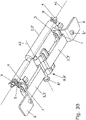
- the invention relates to a locking system for an opening leaf 1, which can be controlled manually on opening, and comprising, on the one hand, a locking member 2 arranged movable in relation to a first axis A1 and, on the other hand , at least one control member 3 with an elongated structure and arranged to pivot around at least a second axis A2, said locking member 2 comprising at least one attachment or engagement element 4 capable of and intended to establish a locking connection for the leaf 1 and at least one element 5 for driving said locking member 2 in displacement, said at least one at least one control member 3 forming a lever arm or tilting pallet and comprising, on the one hand, an operating end 6 situated opposite its end 6' pivotally articulated and, on the other hand, an element 7 of transmission of movement able and intended to cooperate with the drive element 5 of the locking member 2 to move, by direct or indirect action of the user on the end 6 of maneuver, the element or each element of commitment 4 to a position preventing the establishment of the locking connection
- said locking member 2 and the two control members 3 are pivotally articulated with the opening 1.
- a locking system which i) is of simple construction (in particular a single locking member), ii) is mounted directly and entirely on the leaf 1 to be locked in the position of closure and iii) can be released by positive action on at least one of two control members 3 which are distinct, spaced apart and without reciprocal interaction, the action to be carried out being of an identical nature for the two members 3 (comfort, simplicity and flexibility of use).
- constituent movable members 2 and 3 only moving in rotation, they remain substantially in the same size regardless of their position.
- the locking member 2 has a body 2' elongated along the first axis A1, for example a tubular hollow body, and comprises at least two engagement elements 4, for example under form of hooks, spaced apart along said first axis A1, the two drive elements 5, for example in the form of lugs, also being arranged mutually spaced apart along this axis A1, and at each engagement element 4 being advantageously associated with a drive element 5.
- Such a construction limits the size and the need for material, and provides safe and effective temporary securing means (by hooking), as well as easily engageable and releasable (radial hooks engaged and released by simple rotation in opposite directions of the component 2).
- each control member 3 can have its own pivot axis A2 with the body of the opening 1, which allows complete freedom of installation except to allow the mutual cooperation of the elements 4 and 5 and to avoid any interference between the movements of the two control devices 3.
- the first axis A1 and the second axis(ies) A2 are arranged perpendicular to each other, the two control members 3 having a body 3' elongated in a direction substantially parallel to the first axis A1 and arranged oppositely so that their articulated ends 6' are mutually proximal and their operating ends 6 are mutually distal.
- this variant also makes it possible to move the two operating ends 6 away from each other and therefore to separate the two locations from which the unlocking can be controlled (see . figure 5 , 7 and 8 ).
- the two control members form functionally independent tilting pallets 3, are mounted articulated around a single second axis A2 and are arranged in a mutually aligned manner in the direction of extension of their bodies 3 'elongated, the operating ends 6 of the two pallets 3 being arranged opposite one another in the direction of the first axis and the articulated ends 6' of these two pallets 3 advantageously constituting a yoke assembly comprising a tenon 8' of one pallet 3 fitted in a mortise 8 of the other pallet 3, the two being crossed by a rod or pin 8' forming the second axis A2.
- each pallet 3 the operating end 6 is located, in the direction of the outside, just after its movement transmission element 7, which is provided with a face 7' for bearing on the drive element 5 of the locking member 2, the transmission of movement between each of the movement transmission elements 7 and the corresponding drive element 5 being of a unidirectional nature (no transmission of movement possible from the element 5 to the elements 7).
- the maneuvering end 6 is arranged in a plane offset with respect to the support face 7' of the corresponding movement transmission element 7.
- the end 6 can for example be connected to the main part of the elongated body 3' of the member 3 by a secondary part forming a recess.
- the system may comprise at least one return spring 9, urging the pivoting locking member 2 into the locked position, possibly a spring 9 at each longitudinal end of said member 2, the or each return spring being advantageously formed by a spring helical working in torsion along its axis.
- at least one return spring may be provided for each control member 3, urging the latter towards a position of absence of cooperation between the drive element 5 and the end of maneuver concerned 6 (not shown).
- the pivoting locking member 2 with an elongated structure comprises, at a first end, an axial tenon 10 for fixing to the opening 1 and on the side opposite to said first end, an axis 10' for fixing with pivoting on the opening , which is attached, said pivot pin 10' being advantageously fitted fitted in an axial housing of cylindrical shape of the pivoting locking member 2 with an elongated structure, having a lateral opening allowing its insertion into this housing.
- the locking 2 and control 3 members are made by molding a rigid plastic material, together with their respective elements 4, 5, 7, the engagement elements 4 and the drive elements 5 preferably being associated and adjacent in pairs and formed as a part of a single piece two by two.
- the opening 1 may comprise on its visible face, at the locations of the maneuvering ends 6 of the control members 3, clearances allowing easy access and good handling of said ends by the user.
- These ends 6 can be fitted with 6" rubber pads forming support stops in the rest position.
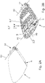
- the invention also relates, as shown by the figure 1 , 2 and 5 to 8 , an opening 1 for closing a box or a cavity in the passenger compartment of a motor vehicle, characterized in that it comprises a controllable locking system on opening as described above, comprising two control devices 3 whose operating ends 6 are remote from each other.
- the opening 1 is connected to the passenger compartment by a pivot connection 12, for example at one of its sides, and the two control members 3 are aligned in a direction parallel to the pivot axis A3 of this link 12.
- the axes A1 and A3 can be parallel to each other (and perpendicular to the axis A2) and the link 12 can be located opposite the locking member 2 on the opening 1, the control members 3, and in particular their ends 6, being for their part located for example between them (cf. figure 2B ), laterally or not.
- the two operating ends 6 of the pallets 3 are spaced apart from each other on the visible face of the opening 1, and possibly arranged on two opposite sides of the opening 1. Conversely, the two operating ends 6 can also be arranged mutually adjacent ( figure 6 ).
- the invention also relates to a motor vehicle comprising at least one closing leaf 1, characterized in that the opening leaf 1 comprises at least one controllable locking system as described above.
- the opening 1 is a closing opening of a housing or storage space 14 formed in the board of the dashboard 13 of said vehicle.
- At least the movement on opening of the opening 1 can be of the assisted or automatic type, by providing for example an elastic means (spring, pneumatic cylinder), possibly associated with a braking means (to have a controlled uniform movement) , or even an electric actuator (jack, rotary electric motor), at or close to the pivot link 12 for example.
- the control of any electric actuator can advantageously be coordinated with the unlocking, for example by means of a sensor or by delayed triggering after action by the user on one of the pallets 3.
Landscapes
- Engineering & Computer Science (AREA)
- Mechanical Engineering (AREA)
- Lock And Its Accessories (AREA)
- Vehicle Step Arrangements And Article Storage (AREA)
Applications Claiming Priority (2)
| Application Number | Priority Date | Filing Date | Title |
|---|---|---|---|
| FR1851825A FR3078546B1 (fr) | 2018-03-02 | 2018-03-02 | Systeme de verrouillage pour ouvrant, notamment d'un ouvrant de fermeture d'un logement dans l'habitacle d'un vehicule automobile |
| PCT/EP2019/055025 WO2019166569A1 (fr) | 2018-03-02 | 2019-02-28 | Système de verrouillage pour ouvrant, notamment d'un ouvrant de fermeture d'un logement dans l'habitable d'un véhicule automobile |
Publications (2)
| Publication Number | Publication Date |
|---|---|
| EP3759300A1 EP3759300A1 (fr) | 2021-01-06 |
| EP3759300B1 true EP3759300B1 (fr) | 2022-04-20 |
Family
ID=62683331
Family Applications (1)
| Application Number | Title | Priority Date | Filing Date |
|---|---|---|---|
| EP19708099.7A Active EP3759300B1 (fr) | 2018-03-02 | 2019-02-28 | Système de verrouillage pour ouvrant, notamment d'un ouvrant de fermeture d'un logement dans l'habitable d'un vehicule automobile |
Country Status (5)
| Country | Link |
|---|---|
| EP (1) | EP3759300B1 (ru) |
| BR (1) | BR112020017913A2 (ru) |
| FR (1) | FR3078546B1 (ru) |
| RU (1) | RU2771089C2 (ru) |
| WO (1) | WO2019166569A1 (ru) |
Family Cites Families (6)
| Publication number | Priority date | Publication date | Assignee | Title |
|---|---|---|---|---|
| JP3052153B2 (ja) * | 1991-01-10 | 2000-06-12 | 株式会社パイオラックス | 自動車のコンソールボックス用等の両開き開閉装置 |
| JP2776148B2 (ja) * | 1992-06-05 | 1998-07-16 | 日産自動車株式会社 | グローブボックスのロック装置 |
| KR101095613B1 (ko) | 2007-01-19 | 2011-12-19 | 가부시키가이샤 파이오락꾸스 | 록킹 장치 |
| FR2962086B1 (fr) * | 2010-07-02 | 2012-08-10 | Faurecia Interieur Ind | Dispositif de rangement pour vehicule automobile comprenant une assistance a l'ouverture |
| KR102084382B1 (ko) * | 2013-11-05 | 2020-03-04 | 현대모비스 주식회사 | 차량용 글로브 박스의 손잡이 구조 |
| FR3041577B1 (fr) * | 2015-09-29 | 2018-09-14 | Faurecia Interieur Industrie | Mecanisme de verrouillage, ensemble interieur de vehicule et vehicule correspondant |
-
2018
- 2018-03-02 FR FR1851825A patent/FR3078546B1/fr active Active
-
2019
- 2019-02-28 RU RU2020132452A patent/RU2771089C2/ru active
- 2019-02-28 BR BR112020017913-2A patent/BR112020017913A2/pt not_active Application Discontinuation
- 2019-02-28 WO PCT/EP2019/055025 patent/WO2019166569A1/fr active Application Filing
- 2019-02-28 EP EP19708099.7A patent/EP3759300B1/fr active Active
Also Published As
| Publication number | Publication date |
|---|---|
| BR112020017913A2 (pt) | 2020-12-22 |
| FR3078546A1 (fr) | 2019-09-06 |
| RU2020132452A (ru) | 2022-04-04 |
| RU2771089C2 (ru) | 2022-04-26 |
| FR3078546B1 (fr) | 2020-09-11 |
| WO2019166569A1 (fr) | 2019-09-06 |
| EP3759300A1 (fr) | 2021-01-06 |
| RU2020132452A3 (ru) | 2022-04-04 |
Similar Documents
| Publication | Publication Date | Title |
|---|---|---|
| EP1920957B1 (fr) | Dispositif de verrouillage à poignée rotative et levier pivotant pour panneau coulissant, dispositif d'obturation et véhicule automobile correspondants. | |
| EP0857598B1 (fr) | Malle arrière pour véhicule découvrable | |
| EP1659247B1 (fr) | Dispositif d'obturation d'une baie à l'aide d'un panneau mobile au moyen de verrouillage participant au déplacement du panneau, et véhicule correspondant | |
| FR2948402A1 (fr) | Commande d'ouverture exterieure d'un ouvrant de vehicule automobile et ouvrant equipe d'une telle commande d'ouverture | |
| EP1728684A1 (fr) | Dispositif elevateur pour coffre de vehicule automobile | |
| EP1916132A1 (fr) | Dispositif de verrouillage à poignée poussoir et levier pour panneau coulissant, dispositif d'obturation et véhicule automobile correspondants. | |
| EP1004730B1 (fr) | Serrure pour portière avant ou arrière de véhicule automobile | |
| EP2072735B1 (fr) | Dispositif d'obturation d'une baie de véhicule automobile à panneau mobile coulissant et rails concentriques, et véhicule automobile correspondant | |
| EP3759300B1 (fr) | Système de verrouillage pour ouvrant, notamment d'un ouvrant de fermeture d'un logement dans l'habitable d'un vehicule automobile | |
| EP2045420B1 (fr) | Système de poignée notamment de crémone, destiné à être implanté sur une face externe de porte, telle qu'une porte de camion frigorifique | |
| FR2601992A1 (fr) | Groupe modulaire serrure cylindrique-barillet | |
| FR2843606A1 (fr) | Porte pour vehicule automobile | |
| EP0791708B1 (fr) | Dispositif de verrouillage d'un ouvrant de véhicule automobile comportant des moyens de blocage de la tringlerie | |
| WO2017157493A1 (fr) | Dispositif vitre affleurant pour porte de vehicule a panneau mobile a moyens de blocage en x, patin, porte et vehicule automobile correspondants | |
| FR2866384A1 (fr) | Cremone, destinee a la manoeuvre d'ouverture et de fermeture d'un ouvrant | |
| EP1189777A1 (fr) | Toit escamotable pour vehicule notamment du type permettant de transformer un coupe en cabriolet et vice versa | |
| EP0352176B1 (fr) | Dispositif de verrouillage d'un boîtier avec couvercle formant par example vide-poches pour véhicule automobile | |
| EP2036774B1 (fr) | Console centrale de véhicule à butée flexible de la façade supérieure | |
| EP1407909B1 (fr) | Dispositif d'obturation d'une baie ménagée dans la carrosserie d'une véhicule automobile, à panneau mobile et pivotant. | |
| EP1433633A1 (fr) | Dispositif d'obturation d'une baie ménagée dans un véhicule automobile, et véhicule correspondant | |
| EP4215701A1 (fr) | Dispositif de commande d'ouverture extérieure | |
| EP1069270A1 (fr) | Poignée d'ouvrant de véhicule automobile comportant des moyens debrayables commandes d'actionnement d'une serrure | |
| FR2905904A1 (fr) | Toit escamotable comprenant un dispositif de verrouillage d'un premier sur un second element | |
| EP4215700A1 (fr) | Mécanisme d'éjection mécanique de poignée | |
| FR2876076A1 (fr) | Structure de coffre de vehicule automobile et vehicule automobile comportant une telle structure |
Legal Events
| Date | Code | Title | Description |
|---|---|---|---|
| STAA | Information on the status of an ep patent application or granted ep patent |
Free format text: STATUS: UNKNOWN |
|
| STAA | Information on the status of an ep patent application or granted ep patent |
Free format text: STATUS: THE INTERNATIONAL PUBLICATION HAS BEEN MADE |
|
| PUAI | Public reference made under article 153(3) epc to a published international application that has entered the european phase |
Free format text: ORIGINAL CODE: 0009012 |
|
| STAA | Information on the status of an ep patent application or granted ep patent |
Free format text: STATUS: REQUEST FOR EXAMINATION WAS MADE |
|
| 17P | Request for examination filed |
Effective date: 20200902 |
|
| AK | Designated contracting states |
Kind code of ref document: A1 Designated state(s): AL AT BE BG CH CY CZ DE DK EE ES FI FR GB GR HR HU IE IS IT LI LT LU LV MC MK MT NL NO PL PT RO RS SE SI SK SM TR |
|
| AX | Request for extension of the european patent |
Extension state: BA ME |
|
| RIN1 | Information on inventor provided before grant (corrected) |
Inventor name: BRACAVAL, THOMAS Inventor name: UTZERI, FRANCO |
|
| DAV | Request for validation of the european patent (deleted) | ||
| DAX | Request for extension of the european patent (deleted) | ||
| RAP3 | Party data changed (applicant data changed or rights of an application transferred) |
Owner name: SMRC AUTOMOTIVE HOLDINGS NETHERLANDS B.V. |
|
| GRAP | Despatch of communication of intention to grant a patent |
Free format text: ORIGINAL CODE: EPIDOSNIGR1 |
|
| STAA | Information on the status of an ep patent application or granted ep patent |
Free format text: STATUS: GRANT OF PATENT IS INTENDED |
|
| INTG | Intention to grant announced |
Effective date: 20211210 |
|
| GRAS | Grant fee paid |
Free format text: ORIGINAL CODE: EPIDOSNIGR3 |
|
| GRAA | (expected) grant |
Free format text: ORIGINAL CODE: 0009210 |
|
| STAA | Information on the status of an ep patent application or granted ep patent |
Free format text: STATUS: THE PATENT HAS BEEN GRANTED |
|
| AK | Designated contracting states |
Kind code of ref document: B1 Designated state(s): AL AT BE BG CH CY CZ DE DK EE ES FI FR GB GR HR HU IE IS IT LI LT LU LV MC MK MT NL NO PL PT RO RS SE SI SK SM TR |
|
| REG | Reference to a national code |
Ref country code: GB Ref legal event code: FG4D Free format text: NOT ENGLISH |
|
| REG | Reference to a national code |
Ref country code: CH Ref legal event code: EP |
|
| REG | Reference to a national code |
Ref country code: DE Ref legal event code: R096 Ref document number: 602019013899 Country of ref document: DE |
|
| REG | Reference to a national code |
Ref country code: IE Ref legal event code: FG4D Free format text: LANGUAGE OF EP DOCUMENT: FRENCH |
|
| REG | Reference to a national code |
Ref country code: AT Ref legal event code: REF Ref document number: 1485264 Country of ref document: AT Kind code of ref document: T Effective date: 20220515 |
|
| REG | Reference to a national code |
Ref country code: LT Ref legal event code: MG9D |
|
| REG | Reference to a national code |
Ref country code: NL Ref legal event code: MP Effective date: 20220420 |
|
| REG | Reference to a national code |
Ref country code: AT Ref legal event code: MK05 Ref document number: 1485264 Country of ref document: AT Kind code of ref document: T Effective date: 20220420 |
|
| PG25 | Lapsed in a contracting state [announced via postgrant information from national office to epo] |
Ref country code: NL Free format text: LAPSE BECAUSE OF FAILURE TO SUBMIT A TRANSLATION OF THE DESCRIPTION OR TO PAY THE FEE WITHIN THE PRESCRIBED TIME-LIMIT Effective date: 20220420 |
|
| PG25 | Lapsed in a contracting state [announced via postgrant information from national office to epo] |
Ref country code: SE Free format text: LAPSE BECAUSE OF FAILURE TO SUBMIT A TRANSLATION OF THE DESCRIPTION OR TO PAY THE FEE WITHIN THE PRESCRIBED TIME-LIMIT Effective date: 20220420 Ref country code: PT Free format text: LAPSE BECAUSE OF FAILURE TO SUBMIT A TRANSLATION OF THE DESCRIPTION OR TO PAY THE FEE WITHIN THE PRESCRIBED TIME-LIMIT Effective date: 20220822 Ref country code: NO Free format text: LAPSE BECAUSE OF FAILURE TO SUBMIT A TRANSLATION OF THE DESCRIPTION OR TO PAY THE FEE WITHIN THE PRESCRIBED TIME-LIMIT Effective date: 20220720 Ref country code: LT Free format text: LAPSE BECAUSE OF FAILURE TO SUBMIT A TRANSLATION OF THE DESCRIPTION OR TO PAY THE FEE WITHIN THE PRESCRIBED TIME-LIMIT Effective date: 20220420 Ref country code: HR Free format text: LAPSE BECAUSE OF FAILURE TO SUBMIT A TRANSLATION OF THE DESCRIPTION OR TO PAY THE FEE WITHIN THE PRESCRIBED TIME-LIMIT Effective date: 20220420 Ref country code: GR Free format text: LAPSE BECAUSE OF FAILURE TO SUBMIT A TRANSLATION OF THE DESCRIPTION OR TO PAY THE FEE WITHIN THE PRESCRIBED TIME-LIMIT Effective date: 20220721 Ref country code: FI Free format text: LAPSE BECAUSE OF FAILURE TO SUBMIT A TRANSLATION OF THE DESCRIPTION OR TO PAY THE FEE WITHIN THE PRESCRIBED TIME-LIMIT Effective date: 20220420 Ref country code: ES Free format text: LAPSE BECAUSE OF FAILURE TO SUBMIT A TRANSLATION OF THE DESCRIPTION OR TO PAY THE FEE WITHIN THE PRESCRIBED TIME-LIMIT Effective date: 20220420 Ref country code: BG Free format text: LAPSE BECAUSE OF FAILURE TO SUBMIT A TRANSLATION OF THE DESCRIPTION OR TO PAY THE FEE WITHIN THE PRESCRIBED TIME-LIMIT Effective date: 20220720 Ref country code: AT Free format text: LAPSE BECAUSE OF FAILURE TO SUBMIT A TRANSLATION OF THE DESCRIPTION OR TO PAY THE FEE WITHIN THE PRESCRIBED TIME-LIMIT Effective date: 20220420 |
|
| PG25 | Lapsed in a contracting state [announced via postgrant information from national office to epo] |
Ref country code: RS Free format text: LAPSE BECAUSE OF FAILURE TO SUBMIT A TRANSLATION OF THE DESCRIPTION OR TO PAY THE FEE WITHIN THE PRESCRIBED TIME-LIMIT Effective date: 20220420 Ref country code: PL Free format text: LAPSE BECAUSE OF FAILURE TO SUBMIT A TRANSLATION OF THE DESCRIPTION OR TO PAY THE FEE WITHIN THE PRESCRIBED TIME-LIMIT Effective date: 20220420 Ref country code: LV Free format text: LAPSE BECAUSE OF FAILURE TO SUBMIT A TRANSLATION OF THE DESCRIPTION OR TO PAY THE FEE WITHIN THE PRESCRIBED TIME-LIMIT Effective date: 20220420 Ref country code: IS Free format text: LAPSE BECAUSE OF FAILURE TO SUBMIT A TRANSLATION OF THE DESCRIPTION OR TO PAY THE FEE WITHIN THE PRESCRIBED TIME-LIMIT Effective date: 20220820 |
|
| REG | Reference to a national code |
Ref country code: DE Ref legal event code: R097 Ref document number: 602019013899 Country of ref document: DE |
|
| PG25 | Lapsed in a contracting state [announced via postgrant information from national office to epo] |
Ref country code: SM Free format text: LAPSE BECAUSE OF FAILURE TO SUBMIT A TRANSLATION OF THE DESCRIPTION OR TO PAY THE FEE WITHIN THE PRESCRIBED TIME-LIMIT Effective date: 20220420 Ref country code: SK Free format text: LAPSE BECAUSE OF FAILURE TO SUBMIT A TRANSLATION OF THE DESCRIPTION OR TO PAY THE FEE WITHIN THE PRESCRIBED TIME-LIMIT Effective date: 20220420 Ref country code: RO Free format text: LAPSE BECAUSE OF FAILURE TO SUBMIT A TRANSLATION OF THE DESCRIPTION OR TO PAY THE FEE WITHIN THE PRESCRIBED TIME-LIMIT Effective date: 20220420 Ref country code: EE Free format text: LAPSE BECAUSE OF FAILURE TO SUBMIT A TRANSLATION OF THE DESCRIPTION OR TO PAY THE FEE WITHIN THE PRESCRIBED TIME-LIMIT Effective date: 20220420 Ref country code: DK Free format text: LAPSE BECAUSE OF FAILURE TO SUBMIT A TRANSLATION OF THE DESCRIPTION OR TO PAY THE FEE WITHIN THE PRESCRIBED TIME-LIMIT Effective date: 20220420 Ref country code: CZ Free format text: LAPSE BECAUSE OF FAILURE TO SUBMIT A TRANSLATION OF THE DESCRIPTION OR TO PAY THE FEE WITHIN THE PRESCRIBED TIME-LIMIT Effective date: 20220420 |
|
| PLBE | No opposition filed within time limit |
Free format text: ORIGINAL CODE: 0009261 |
|
| STAA | Information on the status of an ep patent application or granted ep patent |
Free format text: STATUS: NO OPPOSITION FILED WITHIN TIME LIMIT |
|
| 26N | No opposition filed |
Effective date: 20230123 |
|
| PG25 | Lapsed in a contracting state [announced via postgrant information from national office to epo] |
Ref country code: AL Free format text: LAPSE BECAUSE OF FAILURE TO SUBMIT A TRANSLATION OF THE DESCRIPTION OR TO PAY THE FEE WITHIN THE PRESCRIBED TIME-LIMIT Effective date: 20220420 |
|
| PG25 | Lapsed in a contracting state [announced via postgrant information from national office to epo] |
Ref country code: SI Free format text: LAPSE BECAUSE OF FAILURE TO SUBMIT A TRANSLATION OF THE DESCRIPTION OR TO PAY THE FEE WITHIN THE PRESCRIBED TIME-LIMIT Effective date: 20220420 |
|
| P01 | Opt-out of the competence of the unified patent court (upc) registered |
Effective date: 20230620 |
|
| REG | Reference to a national code |
Ref country code: DE Ref legal event code: R119 Ref document number: 602019013899 Country of ref document: DE |
|
| PG25 | Lapsed in a contracting state [announced via postgrant information from national office to epo] |
Ref country code: MC Free format text: LAPSE BECAUSE OF FAILURE TO SUBMIT A TRANSLATION OF THE DESCRIPTION OR TO PAY THE FEE WITHIN THE PRESCRIBED TIME-LIMIT Effective date: 20220420 |
|
| REG | Reference to a national code |
Ref country code: CH Ref legal event code: PL |
|
| REG | Reference to a national code |
Ref country code: BE Ref legal event code: MM Effective date: 20230228 |
|
| GBPC | Gb: european patent ceased through non-payment of renewal fee |
Effective date: 20230228 |
|
| PG25 | Lapsed in a contracting state [announced via postgrant information from national office to epo] |
Ref country code: LU Free format text: LAPSE BECAUSE OF NON-PAYMENT OF DUE FEES Effective date: 20230228 Ref country code: LI Free format text: LAPSE BECAUSE OF NON-PAYMENT OF DUE FEES Effective date: 20230228 Ref country code: CH Free format text: LAPSE BECAUSE OF NON-PAYMENT OF DUE FEES Effective date: 20230228 |
|
| REG | Reference to a national code |
Ref country code: IE Ref legal event code: MM4A |
|
| PG25 | Lapsed in a contracting state [announced via postgrant information from national office to epo] |
Ref country code: GB Free format text: LAPSE BECAUSE OF NON-PAYMENT OF DUE FEES Effective date: 20230228 |
|
| PG25 | Lapsed in a contracting state [announced via postgrant information from national office to epo] |
Ref country code: IT Free format text: LAPSE BECAUSE OF FAILURE TO SUBMIT A TRANSLATION OF THE DESCRIPTION OR TO PAY THE FEE WITHIN THE PRESCRIBED TIME-LIMIT Effective date: 20220420 Ref country code: IE Free format text: LAPSE BECAUSE OF NON-PAYMENT OF DUE FEES Effective date: 20230228 Ref country code: GB Free format text: LAPSE BECAUSE OF NON-PAYMENT OF DUE FEES Effective date: 20230228 Ref country code: DE Free format text: LAPSE BECAUSE OF NON-PAYMENT OF DUE FEES Effective date: 20230901 |
|
| PG25 | Lapsed in a contracting state [announced via postgrant information from national office to epo] |
Ref country code: BE Free format text: LAPSE BECAUSE OF NON-PAYMENT OF DUE FEES Effective date: 20230228 |
|
| PGFP | Annual fee paid to national office [announced via postgrant information from national office to epo] |
Ref country code: FR Payment date: 20240222 Year of fee payment: 6 |