EP3758536B1 - Verfahren zur herstellung von flüssigkeitsgefüllten kammern - Google Patents
Verfahren zur herstellung von flüssigkeitsgefüllten kammern Download PDFInfo
- Publication number
- EP3758536B1 EP3758536B1 EP19710953.1A EP19710953A EP3758536B1 EP 3758536 B1 EP3758536 B1 EP 3758536B1 EP 19710953 A EP19710953 A EP 19710953A EP 3758536 B1 EP3758536 B1 EP 3758536B1
- Authority
- EP
- European Patent Office
- Prior art keywords
- polymer sheet
- tool
- jig
- flat surface
- chamber
- Prior art date
- Legal status (The legal status is an assumption and is not a legal conclusion. Google has not performed a legal analysis and makes no representation as to the accuracy of the status listed.)
- Active
Links
Images





Classifications
-
- B—PERFORMING OPERATIONS; TRANSPORTING
- B29—WORKING OF PLASTICS; WORKING OF SUBSTANCES IN A PLASTIC STATE IN GENERAL
- B29D—PRODUCING PARTICULAR ARTICLES FROM PLASTICS OR FROM SUBSTANCES IN A PLASTIC STATE
- B29D35/00—Producing footwear
- B29D35/12—Producing parts thereof, e.g. soles, heels, uppers, by a moulding technique
- B29D35/14—Multilayered parts
- B29D35/142—Soles
-
- A—HUMAN NECESSITIES
- A43—FOOTWEAR
- A43B—CHARACTERISTIC FEATURES OF FOOTWEAR; PARTS OF FOOTWEAR
- A43B13/00—Soles; Sole-and-heel integral units
- A43B13/14—Soles; Sole-and-heel integral units characterised by the constructive form
- A43B13/18—Resilient soles
- A43B13/20—Pneumatic soles filled with a compressible fluid, e.g. air, gas
-
- B—PERFORMING OPERATIONS; TRANSPORTING
- B29—WORKING OF PLASTICS; WORKING OF SUBSTANCES IN A PLASTIC STATE IN GENERAL
- B29C—SHAPING OR JOINING OF PLASTICS; SHAPING OF MATERIAL IN A PLASTIC STATE, NOT OTHERWISE PROVIDED FOR; AFTER-TREATMENT OF THE SHAPED PRODUCTS, e.g. REPAIRING
- B29C49/00—Blow-moulding, i.e. blowing a preform or parison to a desired shape within a mould; Apparatus therefor
- B29C49/02—Combined blow-moulding and manufacture of the preform or the parison
- B29C49/06905—Using combined techniques for making the preform
- B29C49/0691—Using combined techniques for making the preform using sheet like material, e.g. sheet blow-moulding from joined sheets
-
- B—PERFORMING OPERATIONS; TRANSPORTING
- B29—WORKING OF PLASTICS; WORKING OF SUBSTANCES IN A PLASTIC STATE IN GENERAL
- B29C—SHAPING OR JOINING OF PLASTICS; SHAPING OF MATERIAL IN A PLASTIC STATE, NOT OTHERWISE PROVIDED FOR; AFTER-TREATMENT OF THE SHAPED PRODUCTS, e.g. REPAIRING
- B29C51/00—Shaping by thermoforming, i.e. shaping sheets or sheet like preforms after heating, e.g. shaping sheets in matched moulds or by deep-drawing; Apparatus therefor
- B29C51/12—Shaping by thermoforming, i.e. shaping sheets or sheet like preforms after heating, e.g. shaping sheets in matched moulds or by deep-drawing; Apparatus therefor of articles having inserts or reinforcements
-
- B—PERFORMING OPERATIONS; TRANSPORTING
- B29—WORKING OF PLASTICS; WORKING OF SUBSTANCES IN A PLASTIC STATE IN GENERAL
- B29C—SHAPING OR JOINING OF PLASTICS; SHAPING OF MATERIAL IN A PLASTIC STATE, NOT OTHERWISE PROVIDED FOR; AFTER-TREATMENT OF THE SHAPED PRODUCTS, e.g. REPAIRING
- B29C65/00—Joining or sealing of preformed parts, e.g. welding of plastics materials; Apparatus therefor
- B29C65/02—Joining or sealing of preformed parts, e.g. welding of plastics materials; Apparatus therefor by heating, with or without pressure
-
- B—PERFORMING OPERATIONS; TRANSPORTING
- B29—WORKING OF PLASTICS; WORKING OF SUBSTANCES IN A PLASTIC STATE IN GENERAL
- B29C—SHAPING OR JOINING OF PLASTICS; SHAPING OF MATERIAL IN A PLASTIC STATE, NOT OTHERWISE PROVIDED FOR; AFTER-TREATMENT OF THE SHAPED PRODUCTS, e.g. REPAIRING
- B29C65/00—Joining or sealing of preformed parts, e.g. welding of plastics materials; Apparatus therefor
- B29C65/02—Joining or sealing of preformed parts, e.g. welding of plastics materials; Apparatus therefor by heating, with or without pressure
- B29C65/18—Joining or sealing of preformed parts, e.g. welding of plastics materials; Apparatus therefor by heating, with or without pressure using heated tools
-
- B—PERFORMING OPERATIONS; TRANSPORTING
- B29—WORKING OF PLASTICS; WORKING OF SUBSTANCES IN A PLASTIC STATE IN GENERAL
- B29D—PRODUCING PARTICULAR ARTICLES FROM PLASTICS OR FROM SUBSTANCES IN A PLASTIC STATE
- B29D35/00—Producing footwear
- B29D35/12—Producing parts thereof, e.g. soles, heels, uppers, by a moulding technique
- B29D35/14—Multilayered parts
- B29D35/148—Moulds or apparatus therefor
-
- A—HUMAN NECESSITIES
- A43—FOOTWEAR
- A43B—CHARACTERISTIC FEATURES OF FOOTWEAR; PARTS OF FOOTWEAR
- A43B13/00—Soles; Sole-and-heel integral units
- A43B13/14—Soles; Sole-and-heel integral units characterised by the constructive form
- A43B13/18—Resilient soles
- A43B13/189—Resilient soles filled with a non-compressible fluid, e.g. gel, water
-
- B—PERFORMING OPERATIONS; TRANSPORTING
- B29—WORKING OF PLASTICS; WORKING OF SUBSTANCES IN A PLASTIC STATE IN GENERAL
- B29K—INDEXING SCHEME ASSOCIATED WITH SUBCLASSES B29B, B29C OR B29D, RELATING TO MOULDING MATERIALS OR TO MATERIALS FOR MOULDS, REINFORCEMENTS, FILLERS OR PREFORMED PARTS, e.g. INSERTS
- B29K2105/00—Condition, form or state of moulded material or of the material to be shaped
- B29K2105/25—Solid
- B29K2105/253—Preform
- B29K2105/256—Sheets, plates, blanks or films
Definitions
- the present disclosure relates to methods of manufacturing fluid-filled chambers and more particularly to methods of manufacturing fluid-filled chambers for incorporation into articles of footwear.
- Articles of footwear conventionally include an upper and a sole structure.
- the upper may be formed from any suitable material(s) to receive, secure, and support a foot on the sole structure.
- the upper may cooperate with laces, straps, or other fasteners to adjust the fit of the upper around the foot.
- Sole structures generally include a layered arrangement extending between a ground surface and the upper.
- One layer of the sole structure includes an outsole that provides abrasion-resistance and traction with the ground surface.
- the outsole may be formed from rubber or other materials that impart durability and wear-resistance, as well as enhancing traction with the ground surface.
- Another layer of the sole structure includes a midsole disposed between the outsole and the upper.
- the midsole provides cushioning for the foot and may include a pressurized fluid-filled chamber that compresses resiliently under an applied load to cushion the foot by attenuating ground-reaction forces.
- Fluid-filled chambers are generally formed from two polymer sheets of material that join together to define a peripheral bond of the fluid-filled chambers.
- a pressurized fluid is then supplied between the two polymer sheets to inflate the chamber.
- a tool having upper and lower mold portions is generally used to impart a desired shape of the chamber and apply heat for joining the two polymer sheets together.
- multiple tools need to be designed and produced to manufacture fluid-filled chambers for each shoe size.
- mold tools are generally specific to the desired shape and, therefore, separate mold tools need to be designed and produced for manufacturing fluid-filled chambers with different shapes.
- EP 2 329 732 A2 relates to a size fitting device adapted to be associated to a wearable article.
- the size fitting device comprises an inflatable member defining an internal chamber, and a plurality of tie members fixed to opposite superficial portions of the inflatable member.
- US 4 999 072 A describes a film encapsulated, gas cushion insole product which maintains its shape by means of a core fabric therein to which a desiccant may be added, if desired. To contain the gas for long periods of time, the film contains a layer of polyvinylalcohol.
- US 2009/288313 A1 relates to a fluid-filled chamber including an outer barrier, a tensile member, and a fluid.
- US 2015/013190A1 describes a sole structure for an article of footwear including a chamber for receiving a pressurized fluid.
- WO 2018/213215 A1 is an Article 54(3) EPC document and relates to a method for forming a fluid-filled chamber and using a jig positioned between the first surface and the first polymer sheet or between the second surface and the second polymer sheet, and the gap between the sheets is maintained within an interior void defined by the jig.
- the objective of this invention is to improve the methods of manufacturing fluid-filled chambers for incorporating into articles of footwear. This objective is achieved by the independent claims and particular embodiments are described in the dependent claims.
- Example configurations will now be described more fully with reference to the accompanying drawings.
- Example configurations are provided so that this disclosure will be thorough, and will fully convey the scope of the disclosure to those of ordinary skill in the art. Specific details are set forth such as examples of specific components, devices, and methods, to provide a thorough understanding of configurations of the present disclosure. It will be apparent to those of ordinary skill in the art that specific details need not be employed, that example configurations may be embodied in many different forms, and that the specific details and the example configurations should not be construed to limit the scope of the invention which is defined by the appended claims.
- first, second, third, etc. may be used herein to describe various elements, components, regions, layers and/or sections. These elements, components, regions, layers and/or sections should not be limited by these terms. These terms may be only used to distinguish one element, component, region, layer or section from another region, layer or section. Terms such as “first,” “second,” and other numerical terms do not imply a sequence or order unless clearly indicated by the context. Thus, a first element, component, region, layer or section discussed below could be termed a second element, component, region, layer or section without departing from the teachings of the example configurations.
- One aspect of the disclosure provides a method of forming a chamber.
- the method includes positioning a first polymer sheet on a substantially first flat surface of a tool, positioning a second polymer sheet on the first polymer sheet, and moving a second substantially flat surface of the tool into contact with the second polymer sheet.
- the method also includes maintaining a gap between the first polymer sheet and the second polymer sheet at a predetermined area and heating one of the two substantially flat surfaces of the tool to heat one of the first polymer sheet and the second polymer sheet.
- the method further includes joining the first polymer sheet and the second polymer sheet together at locations outside of the predetermined area to define a peripheral bond of the chamber.
- Maintaining the gap between the first polymer sheet and the second polymer sheet includes adding a tensile element defining the predetermined area between the first polymer sheet and the second polymer sheet.
- the method also includes heating the one of the two substantially flat surfaces of the tool to potentially heat an entire surface of the one of the two polymer sheets.
- Adding the tensile element defining the predetermined area between the first polymer sheet and the second polymer sheet includes positioning a first tensile layer of the tensile element in contact with the first polymer sheet and positioning a second tensile layer of the tensile element in contact with the second polymer sheet. Heating one of the two substantially flat surfaces of the tool does bond one of the first polymer sheet and the second polymer sheet to a respective one of the first tensile layer and the second tensile layer.
- the method further includes moving the second substantially flat surface of the tool away from the second polymer sheet after joining the first polymer sheet and the second polymer sheet and positioning the second polymer sheet on the substantially first flat surface of the tool.
- the method also includes moving the second substantially flat surface of the tool into contact with the first polymer sheet and heating the one of the two substantially flat surfaces of the tool to heat the other of the first polymer sheet and the second polymer sheet.
- Heating the other of the first polymer sheet and the second polymer sheet may cause the other of the first polymer sheet and the second polymer sheet to bond to a respective one of the first tensile layer and the second tensile layer.
- the method includes heating the other of the two substantially flat surfaces of the tool to heat a surface of the other of the first polymer sheet and the second polymer sheet.
- Joining the first polymer sheet and the second polymer sheet together at locations outside of the predetermined area may include joining the first polymer sheet to the first tensile layer and joining the second polymer sheet to the second tensile layer at locations within the predetermined area.
- the method may further include supplying a pressurized fluid into an area between the first polymer sheet and the second polymer sheet after joining the first polymer sheet and the second polymer sheet together to inflate the chamber.
- Another aspect of the disclosure provides another method of forming a chamber.
- the method includes positioning a jig defining an interior void in a first position on a first surface of a tool, positioning a first polymer sheet on the jig, and positioning a second polymer sheet on the first polymer sheet.
- the method also includes moving a second surface of the tool into contact with the second polymer sheet, heating the tool to heat one of the first polymer sheet and the second polymer sheet, and joining the first polymer sheet and the second polymer sheet together at locations outside of the interior void defined by the jig to define a peripheral bond of the chamber.
- the method includes maintaining a gap between the first polymer sheet and the second polymer sheet.
- the gap has a predetermined area including a shape defined by the interior void of the jig.
- Heating the tool to heat one of the first polymer sheet and the second polymer sheet includes heating the second surface of the tool to heat the second polymer sheet.
- the method includes moving the second surface of the tool away from the second polymer sheet after heating the second polymer sheet, positioning the second polymer sheet on the jig, moving the second surface of the tool into contact with the first polymer sheet, and heating the second surface of the tool to heat the first polymer sheet.
- Positioning the second polymer sheet on the jig may include positioning the peripheral bond on the jig.
- the method may also include moving the second surface of the tool away from the second polymer sheet after heating the second polymer sheet, rotating the jig 180°, and positioning the jig in a second position on the first surface of the tool after rotating the jig 180°.
- the method may further include positioning the second polymer sheet on the jig, moving the second surface of the tool into contact with the first polymer sheet, heating the second surface of the tool to heat the first polymer sheet, and joining the first polymer sheet and the second polymer sheet together at locations outside of the interior void defined by the jig to define the peripheral bond of the chamber.
- the method includes maintaining the gap between the first polymer sheet and the second polymer sheet at the predetermined area within the interior void defined by the jig.
- Positioning the second polymer sheet on the jig may include positioning the peripheral bond on the jig when the jig is in the second position.
- the method may also include supplying a pressurized fluid into an area between the first polymer sheet and the second polymer sheet after joining the first polymer sheet and the second polymer sheet together to inflate the chamber.
- positioning the first polymer sheet on the jig includes positioning a first thermoformed polymer sheet on the jig.
- positioning the second polymer sheet on the first polymer sheet may include positioning a second thermoformed polymer sheet on the first thermoformed polymer sheet.
- positioning the second polymer sheet on the first polymer sheet includes positioning the second polymer sheet that is not thermoformed on the first thermoformed polymer sheet.
- gravity may cause the second polymer sheet to sag relative to the first thermoformed polymer sheet.
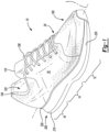
- an article of footwear 10 is provided and includes an upper 100 and a sole structure 200 attached to the upper 100.
- the article of footwear 10 may be divided into one or more portions.
- the portions may include a forefoot portion 12, a mid-foot portion 14, and a heel portion 16.
- the forefoot portion 12 may correspond with toes and joints connecting metatarsal bones with phalanx bones of a foot.
- the mid-foot portion 14 may correspond with an arch area of the foot, and the heel portion 16 may correspond with rear portions of the foot, including a calcaneus bone.
- the footwear 10 may include lateral and medial sides 18, 20, respectively, corresponding with opposite sides of the footwear 10 and extending through the portions 12, 14, 16.
- the upper 100 includes interior surfaces that define an interior void 102 that receives and secures a foot for support on the sole structure 200.
- An ankle opening 104 in the heel portion 16 may provide access to the interior void 102.
- the ankle opening 104 may receive a foot to secure the foot within the void 102 and facilitate entry and removal of the foot to and from the interior void 102.
- one or more fasteners 106 extend along the upper 100 to adjust a fit of the interior void 102 around the foot while concurrently accommodating entry and removal of the foot therefrom.
- the upper 100 may include apertures such as eyelets and/or other engagement features such as fabric or mesh loops that receive the fasteners 106.
- the fasteners 106 may include laces, straps, cords, hook-and-loop, or any other suitable type of fastener.
- the upper 100 may include a tongue portion 110 that extends between the interior void 102 and the fasteners 106.
- the upper 100 may be formed from one or more materials that are stitched or adhesively bonded together to form the interior void 102. Suitable materials of the upper may include, but are not limited, textiles, foam, leather, and synthetic leather. The materials may be selected and located to impart properties of durability, air-permeability, wear-resistance, flexibility, and comfort.
- the sole structure 200 includes an outsole 210 and a strobel 220 arranged in a layered configuration.
- the sole structure 200 (e.g., the outsole 210 and the strobel 220) defines a longitudinal axis L.
- the outsole 210 engages with a ground surface during use of the article of footwear 10 and the strobel 220 is disposed between the upper 100 and the outsole 210.
- the sole structure 200 may also incorporate additional layers such as an insole or sockliner (neither shown), which may reside within the interior void 102 of the upper 100 to receive a plantar surface of the foot to enhance the comfort of the footwear 10.
- a sidewall 230 surrounds a perimeter of the outsole 210 and separates the outsole 210 and the strobel 220 to define a cavity 240 therebetween.
- the cavity 240 receives a fluid-filled chamber 300 filled with a pressurized fluid such as air, nitrogen, helium, sulfur, hexafluoride, or liquids/gels to enhance cushioning characteristics of the footwear 10 in response to ground-reaction forces.
- the fluid-filled chamber 300 defines an interior cavity that receives the pressurized fluid while providing a durable sealed barrier for retaining the pressurized fluid therein.
- the chamber 300 may include a lower barrier portion 301 that opposes the outsole 210 and an upper barrier portion 302 disposed on an opposite side of the chamber 300 than the lower barrier portion 301 and opposing the strobel 220.
- the lower barrier portion 301 may correspond to a first polymer sheet and the upper barrier portion 302 may correspond to a second polymer sheet that joins to the first polymer sheet to define a peripheral bond 350 ( FIGS. 6-9 ) of the chamber 300.
- the peripheral bond 350 defines a predetermined area associated with the interior cavity that receives and retains the pressurized fluid therein. Accordingly, the peripheral bond 350 forms a sidewall 303 that extends around the periphery of the chamber 300 to connect the lower barrier portion 301 to the upper barrier portion 302.
- the interior cavity of the fluid-filled chamber 300 also receives a tensile element 400 having a lower tensile layer 401 that attaches to lower barrier portion 301, an upper tensile layer 402 that attaches to the upper barrier portion 302, and a plurality of tensile elements 430 that extend between the lower and upper tensile layers 401 and 402, respectively, of the tensile element 400.
- Thermobonding may be used to secure the tensile element 400 to the chamber 300.
- the tensile element 400 is operative to prevent the chamber 300 from expanding outward or otherwise distending due to the pressure of the fluid within the internal cavity of the chamber 300. Namely, the tensile element 400 may limit expansion of the chamber 300 when under pressure to retain an intended shape of surfaces of the barrier portions 301 and 302.
- the chamber 300 may define a length that extends substantially parallel to the longitudinal axis L of the sole structure 200 and may be formed to provide contours that conform to a profile of the bottom surface of the foot as well as an inner surface 214 of the outsole 210. In some configurations, the chamber 300 defines a length that only extends through a portion of the length of the sole structure 200. For instance, the chamber 300 may reside in the heel portion 16 of the sole structure 200 to provide cushioning for the heel of the foot. Additionally or alternatively, two or more chambers 300 may reside in the sole structure 200 each defining a length that extends along a portion of the length of the sole structure 200.
- two or more chambers 300 may be layered upon one another that react differently in response to ground-reaction forces to provide gradient cushioning for the foot. While the sole structure 200 may include more than one chamber 300, the sole structure 200 will be described and shown as including a single chamber 300 that extends along the longitudinal axis L from the forefoot portion 12 to the heel portion 16.
- the outsole 210 may include a ground-engaging surface 212 and the opposite inner surface 214.
- the outsole 210 may attach to the upper 100.
- the sidewall 230 extends from the perimeter of the outsole 210 and attaches to the strobel 220 or the upper 100.
- FIG. 1 shows the outsole 210 attaching to the upper 100 proximate to a tip of the forefoot portion 12.
- the outsole 210 generally provides abrasion-resistance and traction with the ground surface during use of the article of footwear 10.
- the outsole 210 may be formed from one or more materials that impart durability and wear-resistance, as well as enhance traction with the ground surface. For example, rubber may form at least a portion of the outsole 210.
- the strobel 220 may include a bottom surface 222 and a footbed 224 disposed on an opposite side of the strobel 220 than the bottom surface 222. Stitching 226 or adhesives may secure the strobel 220 to the upper 100.
- the footbed 224 may be contoured to conform to a profile of the bottom surface (e.g., plantar) of the foot.
- the bottom surface 222 may oppose the inner surface 214 of the outsole 210 to define the cavity 240 therebetween.
- the strobel 220 may be formed from a flexible material that allows the strobel 220 to conform to the fluid-filled chamber 300 residing in the cavity 240 underneath the strobel 220.
- the flexible strobel 220 allows the pressurized fluid retained by the fluid-filled chamber 300 within in the cavity 240 to interact with the profile of the bottom surface of a foot during gradient loading of the sole structure 200.
- the sidewall 230 may define a perimeter of the cavity 240 as well as a depth of the cavity 240 based on a length of separation between the bottom surface 222 and the inner surface 214.
- One or more polymer foam materials may form the sidewall 230 to provide resilient compressibility under applied loads to attenuate ground-reaction forces.
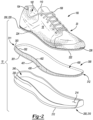
- FIG. 2 provides an exploded view of the article of footwear 10 showing the fluid-filled chamber 300 retaining the pressurized fluid (e.g., air), the inner surface 214 of the outsole 210, and the bottom surface 222 of the strobel 220.
- the length of the chamber 300 may extend between a first end 311 and a second end 312.
- the first end 311 may be disposed proximate to the heel portion 16 of the sole structure 200 and the second end 312 may be disposed proximate to the forefoot portion 12 of the sole structure 200.
- the chamber 300 may also include a thickness extending substantially perpendicular to the longitudinal axis L of the sole structure 200 and a width extending between the lateral side 18 and the medial side 20.
- the length, the width, and the thickness of the chamber 300 may substantially occupy the cavity 240 defined by the inner surface 214 and the bottom surface 222 and may extend through the forefoot, mid-foot, and heel portions 12, 14, 16, respectively, of the outsole 210.
- FIG. 3 is a perspective view of a heat press tool 500 for use in manufacturing the fluid-filled chamber 300 by applying heat and pressure to join the lower barrier portion 301 (e.g., first polymer sheet) and the upper barrier portion 302 (e.g., second polymer sheet) together to define the peripheral bond 350 of the chamber 300.
- the chamber 300 includes the tensile element 400 for limiting expansion of the chamber 300 when the pressurized fluid (e.g., air) is supplied into the internal cavity
- the application of heat and pressure by the heat press tool 500 is also operative to bond the lower barrier portion 301 and the upper barrier portion 302 to respective ones of the lower tensile layer 401 and the upper tensile layer 402.
- the heat press tool 500 includes a housing 510 having a top section 512 and a base section 514.
- a lower platen 516 rigidly attaches to the base section 514 and includes a substantially first flat (planar) surface 501, while an upper platen 518 pivotally attaches to the top section 512 of the housing 512 via an elongate actuation handle 520 and includes a substantially second flat (planar) surface 502.
- the actuation handle 520 has a proximal end pivotally attached to the top section 512 of the housing 510 and a distal end having a gripper portion 522.
- the upper platen 518 is reciprocally movable by the actuation handle 520 relative to the lower platen 516 to operate the tool 500 between an open position when the upper platen 518 is furthest away from the lower platen 516 and a closed position when the upper platen 518 is vertically aligned and proximate to the lower platen 516 such that the first flat surface 501 and the second flat surface 502 are opposing, and in some instances, contacting one another.
- the actuation handle 520 is omitted and one or both of the upper and lower platens 516 and 518 move relative to one another between the open and closed positions in a fully automated manner through the use of one or more actuating mechanisms (none shown).
- FIG. 3 shows the upper platen 518 including one or more heating elements 530 disposed therein that are operable to selectively raise a temperature of the second flat surface 502.
- heating elements are not included in the lower platen 516.
- the lower platen 516 may include one or more heating elements 530 for selecting raising a temperature of the first flat surface 501 while the upper platen 518 may also include the heating elements 530 or omit the heating elements 530.
- the first and second flat surfaces 501 and 502 of the tool 500 are operative to apply sufficient heat and pressure for joining the first and second polymer sheets 301 and 302 together and, thus, define the peripheral bond 350 of the fluid-filled chamber 300.
- the tensile element 400 defines a predetermined area 340 ( FIG. 4 ) and is operative to maintain a gap G between the polymer sheets 301 and 302 at the predetermined area 340 such that the sheets 301 and 302 only join together at locations outside of the predetermined area 340.
- a jig 700 FIG. 12 is positioned between the first flat surface 501 and the first polymer sheet 301 and the gap G between the sheets 301 and 302 is maintained within an interior void 720 ( FIG. 12 ) defined by the jig 700.
- the tool 500 includes a power cord 550 configured to provide power to the tool 500 from an external power source (not shown) for energizing the heating elements 530 to heat the second flat surface 501 to a desired temperature.
- the tool 500 includes an energy storage device (e.g., a battery; not shown) for providing power to energize the heating elements 530.
- the tool 500 may also include data processing hardware 552 for setting the desired temperature of the second flat surface 501.
- FIGS. 4-9 schematic views of the heat press tool 500 of FIG. 3 are provided and include the lower platen 516 and the upper platen 518 operable between the open and closed positions for joining the first polymer sheet 301 and the second polymer sheet 302 together to define the peripheral bond 350 of the fluid-filled chamber 300.
- the fluid-filled chamber 300 may be incorporated into the article of footwear 10 of FIGS. 1 and 2 once formed and inflated.
- the lower platen 516 includes the substantially first flat surface 501 and the upper platen 518 includes the substantially second flat surface 502 and the one or more heating elements 530 disposed therein for raising the temperature (e.g., heating) the second flat surface 502.
- the lower platen 516 may additionally or alternatively include heating elements for raising the temperature of the first flat surface 501 without departing from the scope of the present disclosure.
- the lower platen 516 is fixed and the upper platen 518 translates toward the lower platen 516 to close the heat press tool 500 and thereby apply pressure and heat to the first and second polymer sheets 301 and 302 disposed therebetween.
- the lower platen 516 and the upper platen 518 may each translate toward one another or only the lower patent 516 may translate toward the upper platen 518.
- FIG. 4 shows the tool 500 open and the first polymer sheet 301 positioned on the substantially first flat surface 501 of the tool 500, the second polymer sheet 302 positioned on the first polymer sheet 301, and the tensile element 400 defining the predetermined area 340 disposed between the first polymer sheet 301 and the second polymer sheet 302. More specifically, the first tensile layer 401 of the tensile element 400 is positioned in contact with the first polymer sheet 301 and the second tensile layer 402 of the tensile element 400 is positioned in contact with the second polymer sheet 302.
- the tensile members 430 may be disposed between and connecting the tensile layers 401 and 402.
- the tensile element 400 is operative to maintain the gap G between the first polymer sheet 301 and the second polymer sheet 302 at the predetermined area 340 such that the first polymer sheet 301 and the second polymer sheet 302 are prevented from joining, or otherwise bonding, to one another at locations within the predetermined area 340.
- the upper platen 518 and second flat surface 502 thereof may be moved to the open position in order to expose the first flat surface 501 of the lower platen 516.
- the heating elements 530 begin to heat the second flat surface 502 to a predetermined temperature while the tool 500 is open. As such, the second flat surface 502 may be at a predetermined temperature prior to engaging the second polymer sheet 302.
- the tool 500 may be closed by selectively moving the actuation handle 520 to translate the upper platen 518 toward the lower platen 516.
- FIG. 5 shows the tool 500 closed by moving the second substantially flat surface 502 of the upper platen 518 into contact with the second polymer sheet 302. Moving the second flat surface 502 into contact with the second polymer sheet 302 causes the first polymer sheet 301, the second polymer sheet 302, and the tensile element 400 to compress between the first flat surface 501 and the second flat surface 502 of the heating tool 500.
- the tensile element 400 is operative to maintain the gap G between the first polymer sheet 301 and the second polymer sheet 302 at the predetermined area 340 while the first polymer sheet 301 and the second polymer sheet 302 contact one another at locations outside of the predetermined area 340.
- the heating elements 530 associated with the upper platen 518 apply heat 532 to heat the second flat surface 502 of the tool 500 to a predetermined temperature, thereby heating the second polymer sheet 302 in contact therewith.
- heating the second flat surface 502 of the tool 500 includes heating an entire surface of the second flat surface 502.
- the predetermined temperature includes a temperature suitable for allowing the second polymer sheet 302 to bond with the second tensile layer 402 of the tensile element 400 at the locations within the predetermined area 340, while simultaneously joining with the first polymer sheet 301 at the locations outside of the predetermined area 340 to define the peripheral bond 350 of the chamber 300.
- the lower platen 516 includes heating elements for heating the first flat surface 501 to heat the first polymer sheet 301 in contact therewith to bond with the first tensile layer 401 of the tensile element 400.
- FIG. 6 shows the heating press tool 500 in the open position by moving the second substantially flat surface 502 of the upper platen 518 away from the second polymer sheet 302 after joining the first polymer sheet 301 and the second polymer sheet 302 to define the peripheral bond 350.
- the heat applied by the second substantially flat surface 502 while in contact with the second polymer sheet 302 also allows the second polymer sheet 302 to bond to the second tensile layer 402 of the tensile element 400.
- the heat applied by the second substantially flat surface while in contact with the second polymer sheet 302 is also sufficient to allow the first polymer sheet 301 to bond to the first tensile layer 401 of the tensile element 400.
- the first polymer sheet 301 must also be heated by the second substantially flat surface 502 of the tool 500 while under pressure (e.g., compressed between the two flat surfaces 501 and 502) to bond with the first tensile layer 401 of the tensile element 400.
- FIG. 7 shows the heating press 500 remaining in the open position and the second polymer sheet 302 now positioned on the first flat surface 501 of the tool 500, thereby permitting the heated second flat surface 502 of the tool 500 to contact the first polymer sheet 302 when the tool 500 moves to the closed position by selectively moving the actuation handle 520 to translate the upper platen 518 toward the lower platen 516.
- FIG. 8 shows the tool 500 in the closed position after moving the second substantially flat surface 502 of the upper platen 518 into contact with the second polymer sheet 302. While the polymer sheets 301 and 302 and the tensile element 400 are compressed between the first flat surface 501 and the second flat surface 502 of the tool 500, the heating elements 530 continue to apply heat 532 for heating the second flat surface 502 to heat the first polymer sheet 301 in contact therewith. Accordingly, the heat 532 applied by the second substantially flat surface 502 while in contact with the first polymer sheet 301 allows the first polymer sheet 301 to bond to the first tensile layer 401 of the tensile element 400.
- FIG. 8 shows the tool 500 in the closed position after moving the second substantially flat surface 502 of the upper platen 518 into contact with the second polymer sheet 302. While the polymer sheets 301 and 302 and the tensile element 400 are compressed between the first flat surface 501 and the second flat surface 502 of the tool 500, the heating elements 530 continue to apply heat 532
- the peripheral bond 350 extends around the periphery of the chamber 300 to connect the first polymer sheet 301 (e.g., lower barrier portion 301) to the second polymer sheet 302 (e.g., upper barrier portion). Thereafter, pressurized fluid (e.g., air) may be supplied into an area between the first polymer sheet 301 and the second polymer sheet 302 to inflate the chamber 300 via an inflation port (not shown) inserted between the sheets 301, 302 at a port location along the peripheral bond 350.
- pressurized fluid e.g., air
- the inflation port may be closed by applying heat and pressure to the sheets 301, 302 at the port location to once again seal the bond 350.
- the peripheral bond 350 forms the sidewall 303 extending around the periphery of the chamber 300, while the tensile element 400 is operative to prevent the chamber 300 from expanding outward or otherwise distending due to the pressure of the fluid within the internal cavity of the chamber 300.
- the tensile element 400 may limit expansion of the chamber 300 when under pressure to retain an intended shape of surfaces of the barrier portions 301 and 302.
- the lower platen 516 also includes heating elements for heating the first flat surface 501 while the second flat surface 502 is simultaneously heated by the illustrated heating elements 530.
- the heating of both the first and second flat surfaces 501 and 502 allows the first polymer sheet 301 to bond with the first tensile layer 401 and the second polymer sheet 302 to bond with the second tensile layer 402 concurrently without requiring the second flat surface 502 to heat both of the polymer sheets 301 and 302.
- providing the lower platen 516 with heating elements 530 eliminates the need to rotate/flip the polymer sheets 301 and 302 so that the first polymer sheet 301 can be heated by the second flat surface 502 after the second polymer sheet 302 is heated by the second flat surface 502.
- FIGS. 10 and 11 provide an article of footwear 10a that includes an upper 100 and a sole structure 200a attached to the upper 100.
- like reference numerals are used hereinafter and in the drawings to identify like components while like reference numerals containing letter extensions are used to identify those components that have been modified.
- the sole structure 200a includes the outsole 210 and the strobel 220 arranged in the layered configuration.
- the sidewall 230 may surround the perimeter of the outsole 210 and may separate the outsole 210 and the strobel 220 to define the cavity 240 therebetween.
- the outsole 210 includes an inner surface 214 disposed on an opposite side of the outsole 210 than the ground-engaging surface 212.
- the strobel 220 includes a bottom surface 222 disposed on an opposite side of the strobel 220 than the footbed 224. The bottom surface 222 opposes the inner surface 214 and the sidewall 230 may separate the bottom surface 222 and the inner surface 214 to define a depth of the cavity 240.
- the cavity 240 receives a fluid-filled chamber 300a filled with pressurized fluid (e.g., as air, nitrogen, helium, sulfur, hexafluoride, or liquids/gels) to enhance the cushioning characteristics of the footwear 10a in response to ground-reaction forces.
- the fluid-filled chamber 300a is substantially identical to the fluid-filled chamber 300 of FIGS. 1 and 2 except that the interior cavity of the fluid-filled chamber 300a does not receive the tensile element 400.
- the chamber 300a may include a lower barrier portion 301a that opposes the outsole 210 and an upper barrier portion 302a disposed on an opposite side of the chamber 300a than the lower barrier portion 301a and opposing the strobel 220.
- the lower barrier portion 301a may correspond to a first polymer sheet and the upper barrier portion 302 may correspond to a second polymer sheet that joins to the first polymer sheet to define a peripheral bond 350a ( FIGS. 16-19 ) of the chamber 300a.
- the peripheral bond 350a defines a predetermined area 340a ( FIGS. 14-19 ) associated with the interior cavity that receives and retains the pressurized fluid therein. Accordingly, the peripheral bond 350a forms the sidewall 303 that extends around the periphery of the chamber 300a to connect the lower barrier portion 301a to the upper barrier portion 302a.
- FIG. 11 provides an exploded view of the article of footwear 10a showing the fluid-filled chamber 300a retaining the pressurized fluid (e.g., air), the inner surface 214 of the outsole 210, and the bottom surface 222 of the strobel 220.
- the length of the chamber 300a may extend between the first end 311, disposed proximate to the heel portion 16 of the sole structure 200a, and the second end 312, disposed proximate to the forefoot portion 12 of the sole structure 200a.
- the chamber 300a may also include a thickness extending substantially perpendicular to the longitudinal axis L of the sole structure 200a and a width extending between the lateral side 18 and the medial side 20.
- the length, the width, and the thickness of the chamber 300a may substantially occupy the cavity 240 defined by the inner surface 214 and the bottom surface 222 and may extend through the forefoot, mid-foot, and heel portions 12, 14, 16, respectively, of the outsole 210.
- the fluid-filled chamber 300a may be manufactured using a heat press tool 500a ( FIGS. 14-19 ) that applies heat and pressure to join the lower barrier portion 301a (e.g., first polymer sheet) and the upper barrier portion 302a (e.g., second polymer sheet) together to define the peripheral bond 350a of the chamber 300a.
- the jig 700 defining the interior void 720 is employed to maintain a gap G between the first polymer sheet 301a and the second polymer sheet 302a within the interior void 720.
- the gap G has the predetermined area 340a that includes a shape defined by the interior void 720 of the jig 700 such that the two polymer sheets 301a and 302a join together at locations outside the predetermined area 340a to define the peripheral bond 350a of the chamber 300a.
- FIGS. 12 and 13 provide the jig 700 for use with the heat press tool 500a ( FIGS. 14-19 ) in maintaining the gap G between the first polymer sheet 301a and the second polymer sheet 302a at the predetermined area 340a when forming the chamber 300a.
- the interior void 720 defined by the jig 700 is associated with an asymmetrical shape to form the asymmetrical chamber 300a for incorporation into the article of footwear 10a of FIGS. 10 and 11 .
- the jig 700 is substantially solid and is formed from one or more materials that impart properties of structural rigidity and high compressive strength when under load. In some examples, the jig 700 is formed from silicon.
- the jig 700 may be formed from any rigid materials that can withstand high temperatures such as, without limitation, leather, wood, silicon, and plastic.
- the jig 700 includes a substantially first flat surface 701 and a substantially second flat surface 702 disposed on an opposite side of the jig 700 than the first surface 701.
- the jig 700 defines a length extending from a first end 711 to a second end 712 in a direction parallel to the first and second surfaces 701 and 702, and a thickness extending between the first and second surfaces 701 and 702.
- the interior void 720 defined by the jig 700 is formed entirely through the first and second surfaces 701 and 702 of the jig 700.
- FIG. 13 provides a top view of the jig 700 showing the interior void 720 defining a shape associated with the predetermined area 340a of the gap G to be maintained between the first polymer sheet 301a and the second polymer sheet 302a.
- the interior void 720 may define a length slightly less than the lengths of the polymer sheets 301a and 302a such that the gap is maintained within the interior void 720 and the peripheral bond between the polymer sheets 301a and 302a is formed outside of the interior void 720.
- a heat press tool 500 is provided and includes a lower platen 516 and an upper platen 518 operable between open and closed positions for joining the first polymer sheet 301a and the second polymer sheet 302a together to define the peripheral bond 350a of the fluid-filled chamber 300a for incorporation into the article of footwear 10a of FIGS. 10 and 11 .
- the lower platen 516 includes a substantially first flat surface 501 and the upper platen 518 includes a substantially second flat surface 502.
- the heating elements 530 are disposed in the upper platen 518 for increasing the temperature (e.g., heating) the second flat surface 502.
- the lower platen 516 may additionally or alternatively include heating elements for increasing the temperature of the first flat surface 501 without departing from the scope of the present disclosure.
- the lower platen 516 is fixed and the upper platen 518 translates toward the lower platen 516 to close the heat press tool 500 and thereby apply pressure and heat 532 to the first and second polymer sheets 301a and 302a disposed therebetween.
- the lower platen 516 and the upper platen 518 may each translate toward one another or only the lower platen 516 may translate toward the upper platen 518.
- the lower platen 516 includes heating elements to apply heat 532 in addition to, or in lieu of, applying heat 532 from heating elements 530 disposed in the upper platen 518.
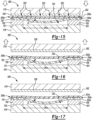
- FIG. 14 shows the heat press tool 500 in the open position and the jig 700 positioned in a first position on the substantially first flat surface 501 of the tool 500, the first polymer sheet 301a positioned on the jig 700, and the second polymer sheet 302a positioned on the first polymer sheet 301a.
- the first position of the jig 700 corresponds to the first flat surface 701 in opposed contact with the first flat surface 501 of the tool 500 and the second flat surface 702 in opposed contact with the first polymer sheet 301a.
- FIG. 14 shows gravity causing the polymer sheets 301a and 302a to sag relative to the first flat surface 701 at locations within the interior void 720.
- the interior void 720 is operative to maintain the gap G between the first polymer sheet 301a and the second polymer sheet 302a within the interior void 720 such that the first polymer sheet 301a and the second polymer sheet 302a are prevented from joining, or otherwise bonding, to one another at the predetermined area 340a including a shape defined by the interior void 720 of the jig 700.
- the gap G prevents the sheets 301a, 302a from contacting one another and, as such, prevents the sheets 301a, 302a from bonding to one another when heat and pressure are applied by the tool 500.
- the heating elements 530 begin to heat the second flat surface 502 to a predetermined temperature while the tool 500 is open. As such, the second flat surface 502 may be at a predetermined temperature prior to engaging the second polymer sheet 302a.
- the tool 500 may close by translating the upper platen 518 toward the lower platen 516.
- FIG. 15 shows the tool 500 closed by moving the second substantially flat surface 502 of the upper platen 518 into contact with the second polymer sheet 302a. Moving the second flat surface 502 into contact with the second polymer sheet 302a causes the jig 700, the first polymer sheet 301a, and the second polymer sheet 302a to compress between the first flat surface 501 and the second flat surface 502 of the heat press tool 500.
- the first polymer sheet 301a and the second polymer sheet 302a compress against one another between the second flat surface 502 of the tool 500 and the jig 700 (e.g., at locations outside the interior void 720), while the gap G is maintained between the two polymer sheets 301a and 302a within the interior void 720 when the tool 500 is in the closed position.
- the interior void 720 defines a shape including the predetermined area 340a such that the gap G is maintained between the two polymer sheets 301a and 302a due to gravity causing the polymer sheets 301a and 302a to sag within the interior void 720.
- heating elements 530 associated with the upper platen 518 heat the second flat surface 502 of the tool 500 to the predetermined temperature to heat the second polymer sheet 302a in contact therewith.
- heating the second flat surface 502 of the tool 500 includes heating an entire surface second flat surface 502.
- the predetermined temperature includes a temperature suitable for allowing the second polymer sheet 302a to join with the first polymer sheet 301a at locations outside of the interior void 720 defined by the jig 700 to define the peripheral bond 350a of the chamber 300a.
- the lower platen 516 additionally or alternatively includes heating elements 530 for heating the first flat surface 501 to heat the first polymer sheet 301a, as described above with respect to the fluid-filled chamber 300.
- FIG. 16 shows the heat press tool 500 in the open position by moving the second substantially flat surface 502 of the upper platen 518 away from the second polymer sheet 302a after joining the first polymer sheet 301a and the second polymer sheet 302a to define the peripheral bond 350a at the locations outside of the interior void 720.
- the peripheral bond 350a may be further strengthened by heating the first polymer sheet 301a and applying pressure to compress the first polymer sheet 301a against the second polymer sheet 302a at the locations outside of the interior void 720.
- the two polymer sheets 301a and 302a may be rotated 180° (e.g., flipped) so that the first polymer sheet 301a can be heated by the substantially second flat surface 502a in configurations when the first platen 516 does not include heating elements 530.
- the chamber 300a defines an asymmetrical shape corresponding to the outline of a foot.
- the jig 700 in order to maintain the gap G between the first polymer sheet 301a and the second polymer sheet 302a at the locations within the interior void 720, the jig 700 must also be rotated 180° (e.g., flipped) so that the second flat surface 702 of the jig 700 is positioned in contact with the substantially first flat surface 501 of the tool 500 and the second polymer sheet 302a is positioned in contact with the first flat surface 701 of the jig 700.
- FIG. 17 shows the heat press tool 500 remaining in the open position while the jig 700 is positioned in a second position on the first flat surface 501 of the tool 500 after rotating the jig 700 180°.
- the second polymer sheet 302a is positioned on the jig 700.
- the second position of the jig 700 corresponds to the second flat surface 702 of the jig 700 now positioned on the first flat surface 501 of the tool 500 to allow the second polymer sheet 302a to be positioned in contact with the jig 700.
- positioning the second polymer sheet 302a in contact with the jig 700 includes positioning the peripheral bond 350a on the jig 700.
- FIG. 18 shows the tool 500 in the closed position after moving the second substantially flat surface 502 of the upper platen 518 into contact with the first polymer sheet 302a.
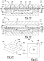
- the gap G between the first polymer sheet 301a and the second polymer sheet 302a is maintained at the locations within the interior void 720 defined by the jig 700.
- the second flat surface 502 heated by the heating elements 530 now heats (via heat 532) the first polymer sheet 301a in contact therewith to further strengthen the peripheral bond 350a at the locations outside of the interior void 720 defined by the jig 700.
- a bond inhibitor is applied between the polymer sheets 301a and 302a within the predetermined area 340a to prevent the polymer sheets 301a and 302a from bonding to each other to create the gap G.
- the bond inhibitor may include placing a printed pigment-based ink within the predetermined area 340a associated with the gap G.
- the pigment-based ink may be printed on a sheet of fabric or paper and the sheet may be placed within the predetermined area 340a.
- the bond inhibitor may include spraying or pressing a pigmented-based ink within the predetermined area 340a.
- the interior cavity of the fluid-filled chamber 300a also receives the tensile element 400 of the article of footwear 10 of FIGS. 1-9 .
- the lower tensile layer 401 may attach to the lower barrier portion 301a
- the upper tensile layer 402 may attach to the upper barrier portion 302a
- the plurality of tensile elements 430 may extend between the lower and upper tensile layers 401 and 402, respectively, of the tensile element 400.
- thermobonding may be used to secure the tensile element 400 to the chamber 300a, and thereby prevent the chamber 300a from expanding outward or otherwise distending due to the pressure of the fluid within the internal cavity of the chamber 300a.
- the tensile element 400 may limit expansion of the chamber 300a when under pressure to retain an intended shape of surfaces of the barrier portions 301a and 302a.
- FIG. 19 shows the heat press tool 500 in the open position after moving the second substantially flat surface 502 of the upper platen 518 away from the first polymer sheet 301a.
- the peripheral bond 350a extends around the periphery of the chamber 300a to connect the first polymer sheet 301a (e.g., lower barrier portion) to the second polymer sheet 302a (e.g., upper barrier portion).
- the pressurized fluid e.g., air
- the peripheral bond 350a forms the sidewall 303 extending around the periphery of the chamber 300a.
- the steps outlined in FIGS. 14-16 where heat 532 is applied directly to the second polymer sheet 302a is sufficient to join the two polymer sheets 301a and 302a together to define the peripheral bond 350a when the two polymer sheets 301a and 302a are compressed together.
- the pressurized fluid e.g., air
- the steps outlined in FIGS. 16-18 that require rotating (e.g., flipping) of both polymer sheets 301a and 302a and the jig 700 180° are optional steps that may serve to further strengthen the peripheral bond 350a therebetween.
- FIGS. 20 and 21 provide a jig 700b for use with a heat press tool 500 ( FIGS. 22-26 ) to form a fluid-filled chamber 300b ( FIG. 27 ) having a symmetrical shape. More specifically, the jig 700b defines an interior void 720b including a symmetrical shape for forming the chamber 300b to provide cushioning for a heel of a foot.
- the chamber 300b may be incorporated into the heel portion 16 of either of the articles of footwear 10, 10a in addition to, or in lieu of, the chambers 300, 300a.
- the chamber 300b defines a length that is shorter than a length of the sole structure 200, 200a.
- the chamber 300b includes a lower barrier portion 301b (e.g., first polymer sheet), an upper barrier portion 302b, and a peripheral bond 350b ( FIGS. 24-26 ) joining the first and second polymer sheets 301b and 302b to define a sidewall 303b extending around the periphery of the fluid-filled chamber 300b.
- a lower barrier portion 301b e.g., first polymer sheet
- an upper barrier portion 302b e.g., first polymer sheet
- a peripheral bond 350b FIGS. 24-26
- the jig 700b is substantially solid and formed from the one or more materials that impart properties of structure rigidity and high compressive strength when under load, e.g., the jig 700b may be formed from silicon or wood.
- the jig 700b includes a substantially first flat surface 701b and a substantially second flat surface 702b disposed on an opposite side of the jig 700b than the first surface 701b.
- the jig 700b defines a length extending from a first end 711b to a second end 712b in a direction substantially parallel to the first and second surfaces 701b and 702b, and a thickness extending between the first and second surfaces 701b and 702b.
- the interior void 720b defined by the jig 700b is formed entirely through the first and second surfaces 701b and 702b of the jig 700b.
- FIG. 21 provides a top view of the jig 700b showing the interior void 720b defining a shape that is symmetrical about a longitudinal axis L of the jig 700b and associated with a predetermined area 340b ( FIG. 22 ) of a gap G ( FIG. 22 ) to be maintained between the first polymer sheet 301b and the second polymer sheet 302b.
- the interior void 720b may define a length slightly less than the lengths of the polymer sheets 301b and 302b such that the gap G is maintained within the interior void 720 and the peripheral bond 350b between the polymer sheets 301b and 302b is formed at locations outside of the interior void 720b.
- the heat press tool 500 is provided and includes a lower platen 516 and an upper platen 518 operable between open and closed positions for joining the first polymer sheet 301b and the second polymer sheet 302b together to define the peripheral bond 350b of the fluid-filled chamber 300b ( FIG. 27 ) for incorporation into the heel region 16 of an article of footwear 10, 10a.
- the lower platen 516 of the heat press tool 500 includes a substantially first flat surface 501 and the upper platen 518 of the heat press tool 500 includes a substantially second flat surface 502.
- the heating elements 530 are disposed in the upper platen 518 for increasing the temperature (e.g., heating) of the second flat surface 502.
- the lower platen 516 may additionally or alternatively include heating elements for increasing the temperature of the first flat surface 501 without departing from the scope of the present disclosure.
- the lower platen 516 is fixed and the upper platen 518 translates toward the lower platen 516 to close the heat press tool 500 and thereby apply pressure and heat to the first and second polymer sheets 301b and 302b disposed therebetween.
- the lower platen 516 and the upper platen 518 may each translate toward one another or only the lower patent 516 may translate toward the upper platen 518.
- FIG. 22 shows the heat press tool 500 in the open position and the jig 700b positioned in the first position on the first flat surface 501 of the tool 500, the first polymer sheet 301b positioned on the jig 700b, and the second polymer sheet 302b positioned on the first polymer sheet 301b.
- the first position of the jig 700b corresponds to the first flat surface 701b in opposed contact with the first flat surface 501 of the tool 500 and the second flat surface 702b in opposed contact with the first polymer sheet 301b.
- FIG. 22 shows gravity causing the polymer sheets 301b and 302b to sag relative to the first flat surface 701b at locations within the interior void 720b.
- the interior void 720b is operative to maintain the gap G between the first polymer sheet 301b and the second polymer sheet 302b within the interior void 720b such that the first polymer sheet 301b and the second polymer sheet 302b are prevented from joining, or otherwise bonding, to one another at a predetermined area 340b including a shape defined by the interior void 720b of the jig 700b.
- the heating elements 530 begin to heat the second flat surface 502 to a predetermined temperature while the tool 500 is open. As such, the second flat surface 502 may be at a predetermined temperature prior to engaging the second polymer sheet 302b.
- the tool 500 may closed by translating the upper platen 518 toward the lower platen 516.
- FIG. 23 shows the tool 500 being closed by moving the second substantially flat surface 502 of the upper platen 518 into contact with the second polymer sheet 302b. Moving the second flat surface 502 into contact with the second polymer sheet 302b causes the jig 700b, the first polymer sheet 301b, and the second polymer sheet 302b to compress between the first flat surface 501 and the second flat surface 502 of the heating tool 500.
- the first polymer sheet 301b and the second polymer sheet 302b compress against one another between the second flat surface 502 of the tool 500 and the jig 700b (e.g., at locations outside the interior void 720b), while the gap G is maintained between the two polymer sheets 301a and 302b at the predetermined area 340b within the interior void 720b when the tool 500 is in the closed position.
- the interior void 720b defines a shape including the predetermined area 340b such that the gap G is maintained between the two polymer sheets 301b and 302b do to gravity causing the polymer sheets 301b and 302b to sag within the interior void 720b.
- the heating elements 530 associated with the upper platen 518 apply heat 532 to the second flat surface 502 of the tool 500 to a predetermined temperature to heat the second polymer sheet 302b in contact therewith.
- heating the second flat surface 502 of the tool 500 includes heating the entire second flat surface 502.
- the predetermined temperature includes a temperature suitable for allowing the second polymer sheet 302b to join with the first polymer sheet 301b at locations outside of the interior void 720b defined by the jig 700b to define the peripheral bond 350b of the chamber 300b.
- the lower platen 516 includes heating elements 530 for heating the first flat surface 501 to heat the first polymer sheet 301b simultaneously with the second polymer sheet 302b.
- FIG. 24 shows the heating press tool 500 in the open position by moving the second substantially flat surface 502 of the upper platen 518 away from the second polymer sheet 302b after joining the first polymer sheet 301b and the second polymer sheet 302b to define the peripheral bond 350b at the locations outside of the interior void 720b defined by the jig 700b.
- the peripheral bond 350b may be further strengthened by heating the first polymer sheet 301b and applying pressure to compress the first polymer sheet 301b against the second polymer sheet 302b at the locations outside of the interior void 720b.
- the two polymer sheets 301b and 302b may be rotated 180° (e.g., flipped) so that the first polymer sheet 301b can be heated by the substantially second flat surface 502 in configurations when the first platen 516 does not include heating elements.
- the jig 700b may remain in the first position on the first flat surface 501 of the tool 500 while the second polymer sheet 302b is positioned in contact with the first flat surface 701b of the jig 700b.
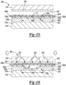
- FIG 25 shows the heating press tool 500 remaining in the open position while the jig 700b remains positioned in the first position on the first flat surface 501 of the tool 500 after the second polymer sheet 302b is positioned on the jig 700b underneath the first polymer sheet 301b.
- positioning the second polymer sheet 302b in contact with the jig 700b includes positioning the peripheral bond 350b on the jig 700b.
- FIG. 26 shows the tool 500 in the closed position after moving the second substantially flat surface 502 of the upper platen 518 into contact with the first polymer sheet 301b.
- the gap G between the first polymer sheet 301b and the second polymer sheet 302b is maintained at the locations within the interior void 720b defined by the jig 700b.
- the second flat surface 502 heated by the heating elements 530 now applies the heat 532 to the first polymer sheet 301b in contact therewith to further strengthen the peripheral bond 350b at the locations outside of the interior void 720b defined by the jig 700b.
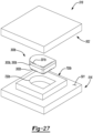
- FIG. 27 provides a perspective view of the heating press tool 500 in the open position after forming the chamber 300b by joining the first polymer sheet 301b to the second polymer sheet 301b at the peripheral bond 350b.
- the peripheral bond 350b extends around the periphery of the chamber 300b to connect the first polymer sheet 301b (e.g., lower barrier portion) to the second polymer sheet 302b (e.g., upper barrier portion).
- pressurized fluid e.g., air
- the peripheral bond 350b forms the sidewall 303b extending around the periphery of the chamber 300b. Accordingly, the fluid-filled chamber 300b may be incorporated into any of the articles of footwear 10, 10a to provide cushioning for the foot in the heel portion 16.
- a first thermoformed polymer sheet 301c and a second thermoformed polymer sheet 302c join together at a peripheral bond 350d to form a fluid-filled chamber 300c ( FIG. 32 ).
- the chamber 300c may be incorporated into the heel portion 16 of either of the articles of footwear 10, 10a in addition to, or in lieu of, the chambers 300, 300a.
- the heat press tool 500 is provided and includes a lower platen 516 and an upper platen 518 operable between open and closed positions.
- the lower platen 516 and upper platen 518 may be used to join the first thermoformed polymer sheet 301c and the second thermoformed polymer sheet 302c together by defining a peripheral bond 350c of the fluid-filled chamber 300c ( FIG. 33 ). Once formed, the fluid-filled chamber 300c may be incorporated into an article of footwear 10, 10a. The sheets 301c and 302c may be thermoformed to define a shape of the fluid-filled chamber 300c. As with the heat press tools 500 of FIGS. 3-19 and 22-26 , the lower platen 516 of the heat press tool 500 includes a substantially first flat surface 501 and the upper platen 518 of the heat press tool 500 includes a substantially second flat surface 502.
- the heating elements 530 are disposed in the upper platen 518 for increasing the temperature (e.g., heating) of the second flat surface 502.
- the lower platen 516 may additionally or alternatively include heating elements for increasing the temperature of the first flat surface 501 without departing from the scope of the present disclosure.
- the lower platen 516 is fixed and the upper platen 518 translates toward the lower platen 516 to close the heat press tool 500 and thereby apply pressure and heat to the first and second thermoformed polymer sheets 301c and 302c disposed therebetween.
- the lower platen 516 and the upper platen 518 may each translate toward one another or only the lower platen 516 may translate toward the upper platen 518.
- FIG. 28 shows the heat press tool 500 in the open position and a jig 700c positioned on the first flat surface 501 of the tool 500, the first thermoformed polymer sheet 301c positioned on the jig 700c, and the second thermoformed polymer sheet 302c positioned on the first polymer sheet 301c.
- the jig 700c includes a first flat surface 701c in opposed contact with the first flat surface 501 of the tool 500 and a second flat surface 702c in opposed contact with the first thermoformed polymer sheet 301c.
- the jig 700c defines an interior void 720c that may accommodate the surface profile of the first thermoformed polymer sheet 301c and the surface profile of the second thermoformed polymer sheet 302c may nest with the first thermoformed polymer sheet 301c within the interior void 720c.
- the polymer sheet 302c is not thermoformed and is simply positioned on top of the first thermoformed polymer sheet 301c, whereby gravity causes the second polymer sheet 302c to sag relative to the first flat surface 701c at locations within the interior void 720c.
- the polymer sheets 301c and 302c are thermoformed to include shapes that are curved or more arcuate.
- the interior void 720c compensates for a thickness or depth of the chamber 300c within a predetermined area 340c where the thermoformed polymer sheets 301c and 302c are prevented from joining, or otherwise, bonding to one another.
- the heating elements 530 begin to heat the second flat surface 502 to a predetermined temperature while the tool 500 is open.
- the second flat surface 502 may be at a predetermined temperature prior to engaging the second thermoformed polymer sheet 302c.
- the jig 700c may define the interior void 720c having a symmetrical shape to form the fluid-filled chamber 300c ( FIG. 33 ) having a corresponding symmetrical shape to provide cushioning for a heel of a foot.
- the jig 700c, the heat press tool 500, and the use of at least one thermoformed polymer sheets 301c and 302c may form a fluid-filled chamber having a shape (e.g., asymmetrical) substantially identical to the fluid-filled chambers 300, 300a.
- the tool 500 may be closed by translating the upper platen 518 toward the lower platen 516.
- FIG. 29 shows the tool 500 being closed by moving the second substantially flat surface 502 of the upper platen 518 into contact with the second thermoformed polymer sheet 302c. Moving the second flat surface 502 into contact with the second thermoformed polymer sheet 302c causes the jig 700c, the first thermoformed polymer sheet 301c, and the second thermoformed polymer sheet 302c to compress between the first flat surface 501 and the second flat surface 502 of the heating tool 500.
- first thermoformed polymer sheet 301c and the second thermoformed polymer sheet 302c compress against one another between the second flat surface 502 of the tool 500 and the jig 700c (e.g., at locations outside the interior void 720c), while the portions of the two polymer sheets 301c and 302c within predetermined area 340c that are not to be joined/bonded nest within the interior void 720c when the tool 500 is in the closed position.
- the heating elements 530 associated with the upper platen 518 apply heat 532 to the second flat surface 502 of the tool 500 to a predetermined temperature to heat the second thermoformed polymer sheet 302c in contact therewith.
- heating the second flat surface 502 of the tool 500 includes heating the entire second flat surface 502.
- the predetermined temperature includes a temperature suitable for allowing the second thermoformed polymer sheet 302c to join with the first thermoformed polymer sheet 301c at locations outside of the interior void 720c defined by the jig 700c to define the peripheral bond 350c of the chamber 300c.
- FIG. 30 shows the heating press tool 500 in the open position by moving the second substantially flat surface 502 of the upper platen 518 away from the second thermoformed polymer sheet 302c after joining the first thermoformed polymer sheet 301c and the second thermoformed polymer sheet 302c to define the peripheral bond 350c at the locations outside of the interior void 720c defined by the jig 700c.
- the peripheral bond 350c may form an offset seam located around the peripheral edges of the sheets 301c and 302c.
- FIG. 31 shows the first and second thermoformed polymer sheets 301c and 302c removed from the tool 500 after forming the peripheral bond 350c at the locations outside the predetermined area 340c.
- the chamber 300c is deflated.
- one of the thermoformed polymer sheets 301c and 302c defines a port 304 operative to fluidly couple the chamber 300c to a fluid source 800 containing a pressurized fluid (e.g., air) 850.
- the port 304 receives a conduit 802 extending from the fluid source 800 to supply the pressurized fluid 850 into the port 304 to inflate the chamber 300c.
- FIG. 32 shows the fluid source 800 inflating the chamber 300c by delivering the pressurized fluid 850 through the port 304 via the conduit 802 and into an internal cavity between the first and second thermoformed polymer sheets 301c and 302c.
- the peripheral bond 350c seals the chamber 300c and allows pressure P within the internal cavity 352 to increase.
- the pressure P causes inversion of the second thermoformed polymer sheet 302c such that the thermoformed polymer sheets 301c and 302c expand away from one another as the chamber 300c inflates.
- the peripheral bond 350c forms the sidewall 303c extending around the periphery of the chamber 300c.
- FIG. 33 provides a perspective view of the chamber 300c formed after inflating the chamber 300c and sealing the port 304.
- the chamber 300c may be incorporated into the heel portion 16 of any of the articles of the footwear 10, 10a.
- the peripheral bond 350c associated with the offset seam forms the sidewall 303c extending around the periphery of the chamber 300c.
- the jig 700c, the heat press tool 500, and the use of at least one thermoformed polymer sheets 301c and 302c may form a fluid-filled chamber having any shape suitable to provide cushioning for the foot in at least one of the forefoot, mid-foot, and heel portions 12, 14, 16, respectively, of either of the articles of footwear 10, 10a.
Landscapes
- Engineering & Computer Science (AREA)
- Mechanical Engineering (AREA)
- Manufacturing & Machinery (AREA)
- Lining Or Joining Of Plastics Or The Like (AREA)
- Footwear And Its Accessory, Manufacturing Method And Apparatuses (AREA)
Claims (12)
- Ein Verfahren zur Bildung einer fluidgefüllten Kammer (300, 300a, 300b) für den Einbau in einen Fußbekleidungsartikel, wobei das Verfahren Folgendes umfasst:Positionieren einer ersten Polymerfolie (301, 301a, 301b) auf einer im Wesentlichen ersten flachen Oberfläche (501) eines Werkzeugs (500, 500a);Positionieren einer zweiten Polymerfolie (302, 302a, 302b) auf der ersten Polymerfolie (301, 301a, 301b);Bewegen einer zweiten im Wesentlichen flachen Oberfläche des Werkzeugs (500, 500a), sodass sie mit der zweiten Polymerfolie (302, 302a, 302b) in Kontakt kommt;Aufrechterhalten eines Zwischenraums zwischen der ersten Polymerfolie (301, 301a, 301b) und der zweiten Polymerfolie (302, 302a, 302b) in einem vorbestimmten Bereich (340, 340a, 340b);Erhitzen einer der beiden im Wesentlichen flachen Oberflächen des Werkzeugs (500, 500a), um eine von der ersten Polymerfolie (301, 301a, 301b) und der zweiten Polymerfolie (302, 302a, 302b) zu erhitzen;Zusammenfügen der ersten Polymerfolie (301, 301a, 301b) und der zweiten Polymerfolie (302, 302a, 302b) an Stellen außerhalb des vorbestimmten Bereichs (340, 340a, 340b), um eine Umfangsbindung bzw. periphere Verklebung (peripheral bond) (350, 350a) der Kammer (300, 300a, 300b) zu definieren;das Aufrechterhalten des Zwischenraums zwischen der ersten Polymerfolie (301) und der zweiten Polymerfolie (302) beinhaltet das Hinzufügen eines Zugelements, das den vorbestimmten Bereich (340) zwischen der ersten Polymerfolie (301) und der zweiten Polymerfolie (302) definiert;das Hinzufügen des Zugelements, das den vorbestimmten Bereich (340) zwischen der ersten Polymerfolie (301) und der zweiten Polymerfolie (302) definiert, beinhaltet das Positionieren einer ersten Zugschicht des Zugelements in Kontakt mit der ersten Polymerfolie (301) und das Positionieren einer zweiten Zugschicht des Zugelements in Kontakt mit der zweiten Polymerfolie (302);das Erhitzen einer der beiden im Wesentlichen flachen Oberflächen des Werkzeugs (500) verbindet eine von der ersten Polymerfolie (301) und der zweiten Polymerfolie (302) mit einer jeweiligen von der ersten Zugschicht und der zweiten Zugschicht;Bewegen der zweiten im Wesentlichen flachen Oberfläche des Werkzeugs (500) weg von der zweiten Polymerfolie (302) nach dem Zusammenfügen der ersten Polymerfolie (301) und der zweiten Polymerfolie (302),Positionieren der zweiten Polymerfolie (302) auf der im Wesentlichen ersten flachen Oberfläche (501) des Werkzeugs (500);Bewegen der zweiten im Wesentlichen flachen Oberfläche (502) des Werkzeugs (500), sodass sie mit der ersten Polymerfolie (301) in Kontakt kommt; undErhitzen der einen von den beiden im Wesentlichen flachen Oberflächen (501, 502) des Werkzeugs (500), um die andere von der ersten Polymerfolie (301) und der zweiten Polymerfolie (302) zu erhitzen.
- Das Verfahren nach Anspruch 1, wobei das Erhitzen der einen von den beiden im Wesentlichen flachen Oberflächen des Werkzeugs (500) eine gesamte Oberfläche der einen von den beiden Polymerfolien erwärmt.
- Das Verfahren nach Anspruch 1, wobei das Erhitzen der anderen von der ersten Polymerfolie (301) und der zweiten Polymerfolie (302) bewirkt, dass die andere von der ersten Polymerfolie (301) und der zweiten Polymerfolie (302) mit einer von der ersten Zugschicht bzw. der zweiten Zugschicht verklebt wird.
- Das Verfahren nach Anspruch 1, das ferner Folgendes umfasst: Erhitzen der anderen von den beiden im Wesentlichen flachen Oberflächen (501, 502) des Werkzeugs (500), um eine Oberfläche der anderen von der ersten Polymerfolie (301) und der zweiten Polymerfolie (302) zu erhitzen.
- Das Verfahren nach Anspruch 4, wobei das Zusammenfügen der ersten Polymerfolie (301) und der zweiten Polymerfolie (302) an Stellen außerhalb des vorbestimmten Bereichs (340) das Zusammenfügen der ersten Polymerfolie (301) mit der ersten Zugschicht und das Zusammenfügen der zweiten Polymerfolie (302) mit der zweiten Zugschicht an Stellen innerhalb des vorbestimmten Bereichs (340) beinhaltet.
- Das Verfahren nach Anspruch 1, das ferner Folgendes umfasst: Zuführen eines unter Druck stehenden Fluids in einen Bereich zwischen der ersten Polymerfolie (301, 301a, 301b) und der zweiten Polymerfolie (302, 302a, 302b), um die Kammer (300, 300a, 300b) aufzublasen nachdem die erste Polymerfolie (301, 301a, 301b) und die zweite Polymerfolie (302, 302a, 302b) zusammengefügt wurden.
- Ein Verfahren zur Bildung einer fluidgefüllten Kammer (300, 300a, 300b) für den Einbau in einen Fußbekleidungsartikel, wobei das Verfahren Folgendes umfasst:Positionieren einer Vorrichtung (jig) (700, 700b), die einen inneren Hohlraum (720) definiert, in einer ersten Position auf einer ersten Oberfläche eines Werkzeugs (500a);Positionieren einer ersten Polymerfolie (301b) auf der Vorrichtung (700, 700b);Positionieren einer zweiten Polymerfolie (302b) auf der ersten Polymerfolie (301b);Bewegen einer zweiten Oberfläche des Werkzeugs (500a), sodass sie mit der zweiten Polymerfolie (302b) in Kontakt kommt;Erhitzen des Werkzeugs (500a), um eines von der ersten Polymerfolie (301b) und der zweiten Polymerfolie (302b) zu erhitzen;Zusammenfügen der ersten Polymerfolie (301b) und der zweiten Polymerfolie (302b) an Stellen außerhalb des durch die Vorrichtung (700, 700b) definierten inneren Hohlraums (720), um eine Umfangsbindung bzw. periphere Verklebung (peripheral bond) (350b) der Kammer (300b) zu definieren;Aufrechterhalten eines Zwischenraums zwischen der ersten Polymerfolie (301b) und der zweiten Polymerfolie (302b), wobei der Zwischenraum eine vorbestimmte Fläche aufweist, die eine durch den inneren Hohlraum (720b) der Vorrichtung (700, 700b) definierte Form beinhaltet,wobei das Erhitzen des Werkzeugs (500a) zum Erhitzen eines von der ersten Polymerfolie (301b) und der zweiten Polymerfolie (302b) das Erhitzen der zweiten Oberfläche des Werkzeugs zum Erhitzen der zweiten Polymerfolie (302b) beinhaltet;Bewegen der zweiten Oberfläche des Werkzeugs weg von der zweiten Polymerfolie nach dem Erhitzen der zweiten Polymerfolie (302b);Positionieren der zweiten Polymerfolie (302b) auf der Vorrichtung (700, 700b);Bewegen der zweiten Oberfläche des Werkzeugs, sodass sie mit der ersten Polymerfolie (301b) in Kontakt kommt; undErhitzen der zweiten Oberfläche des Werkzeugs, um die erste Polymerfolie (301b) zu erhitzen.
- Das Verfahren nach Anspruch 7, wobei das Positionieren der zweiten Polymerfolie (302b) auf der Vorrichtung (700, 700b) das Positionieren der peripheren Verklebung (350b) auf der Vorrichtung (700, 700b) beinhaltet.
- Das Verfahren nach Anspruch 7, das ferner Folgendes umfasst:Bewegen der zweiten Oberfläche des Werkzeugs (500a) weg von der zweiten Polymerfolie nach dem Erhitzen der zweiten Polymerfolie (302b);Drehen der Vorrichtung um 180°;Positionieren der Vorrichtung (700, 700b) in einer zweiten Position auf der ersten Oberfläche des Werkzeugs nach dem Drehen der Vorrichtung um 180°;Positionieren der zweiten Polymerfolie (302b) auf der Vorrichtung (700, 700b);Bewegen der zweiten Oberfläche des Werkzeugs (500a), sodass sie mit der ersten Polymerfolie (301b) in Kontakt kommt;Erhitzen der zweiten Oberfläche des Werkzeugs (500a), um die erste Polymerfolie (301b) zu erhitzen; undZusammenfügen der ersten Polymerfolie (301b) und der zweiten Polymerfolie (302b) an Stellen außerhalb des durch die Vorrichtung (700, 700b) definierten inneren Hohlraums (720b), um die periphere Verklebung (350b) der Kammer (300b) zu definieren.
- Das Verfahren nach Anspruch 9, das ferner Folgendes umfasst:
Aufrechterhalten des Zwischenraums zwischen der ersten Polymerfolie (301b) und der zweiten Polymerfolie (302b) im vorbestimmten Bereich innerhalb des durch die Vorrichtung (700, 700b) definierten inneren Hohlraums (720b). - Das Verfahren nach Anspruch 9, wobei das Positionieren der zweiten Polymerfolie (302b) auf der Vorrichtung (700, 700b) das Positionieren der peripheren Verklebung (350b) auf der Vorrichtung (700, 700b) beinhaltet, wenn sich die Vorrichtung (700, 700b) in der zweiten Position befindet.
- Das Verfahren nach Anspruch 7, das ferner Folgendes umfasst:
Zuführen eines unter Druck stehenden Fluids in einen Bereich zwischen der ersten Polymerfolie (301b) und der zweiten Polymerfolie (302b) nach dem Zusammenfügen der ersten Polymerfolie (301b) und der zweiten Polymerfolie (302b), um die Kammer (300b) aufzublasen, und/oder wobei das Positionieren einer ersten Polymerfolie (301b) auf der Vorrichtung (700, 700b) das Positionieren einer ersten warmgeformten Polymerfolie (301c) auf der Vorrichtung beinhaltet, wobei, optional, das Positionieren einer zweiten Polymerfolie (302b) auf der ersten Polymerfolie (301b) das Positionieren einer zweiten warmgeformten Polymerfolie (302c) auf der ersten warmgeformten Polymerfolie umfasst.
Applications Claiming Priority (3)
| Application Number | Priority Date | Filing Date | Title |
|---|---|---|---|
| US201862636883P | 2018-03-01 | 2018-03-01 | |
| US16/289,161 US11186055B2 (en) | 2018-03-01 | 2019-02-28 | Method of manufacturing fluid-filled chambers |
| PCT/US2019/020210 WO2019169222A1 (en) | 2018-03-01 | 2019-03-01 | Method of manufacturing fluid-filled chambers |
Publications (2)
| Publication Number | Publication Date |
|---|---|
| EP3758536A1 EP3758536A1 (de) | 2021-01-06 |
| EP3758536B1 true EP3758536B1 (de) | 2024-12-04 |
Family
ID=67767353
Family Applications (1)
| Application Number | Title | Priority Date | Filing Date |
|---|---|---|---|
| EP19710953.1A Active EP3758536B1 (de) | 2018-03-01 | 2019-03-01 | Verfahren zur herstellung von flüssigkeitsgefüllten kammern |
Country Status (4)
| Country | Link |
|---|---|
| US (4) | US11186055B2 (de) |
| EP (1) | EP3758536B1 (de) |
| CN (2) | CN120770613A (de) |
| WO (1) | WO2019169222A1 (de) |
Families Citing this family (1)
| Publication number | Priority date | Publication date | Assignee | Title |
|---|---|---|---|---|
| WO2021086878A1 (en) * | 2019-10-29 | 2021-05-06 | Biomerieux, Inc. | Assay devices and methods of manufacture |
Family Cites Families (34)
| Publication number | Priority date | Publication date | Assignee | Title |
|---|---|---|---|---|
| US3289281A (en) * | 1963-07-09 | 1966-12-06 | Reynolds Metals Co | Manufacture of bonded and inflated sheet laminations |
| US3281301A (en) * | 1963-12-11 | 1966-10-25 | Us Rubber Co | Method of making rigid laminate of thermoplastic sheets having increased load-bearing ability |
| US4025974A (en) * | 1972-01-10 | 1977-05-31 | Lea James M | Air mattress and method of making the same |
| US3982877A (en) * | 1974-02-15 | 1976-09-28 | E. I. Du Pont De Nemours And Company | Apparatus for expanding sealing a laminated plastic preform |
| US4999072A (en) | 1987-10-19 | 1991-03-12 | Milliken Research Corporation | Method of making an insole product |
| US5108532A (en) * | 1988-02-02 | 1992-04-28 | Northrop Corporation | Method and apparatus for shaping, forming, consolidating and co-consolidating thermoplastic or thermosetting composite products |
| US5042176A (en) * | 1989-01-19 | 1991-08-27 | Robert C. Bogert | Load carrying cushioning device with improved barrier material for control of diffusion pumping |
| US5283028A (en) * | 1990-05-02 | 1994-02-01 | Penda Corporation | Process for producing a selectively reinforced thermoformed article |
| US5225015A (en) * | 1991-04-15 | 1993-07-06 | Corning Incorporated | Method for making stiffened ceramic matrix composite panel |
| DE4200041A1 (de) * | 1992-01-02 | 1993-08-05 | Kneissl Dachstein Sportartikel | Laufsohle, insbesondere fuer einen wander- oder bergschuh |
| US5460773A (en) * | 1993-08-11 | 1995-10-24 | Fritz; Michael L. | Seal for blow down platen |
| JPH081698A (ja) * | 1994-06-15 | 1996-01-09 | Sumitomo Chem Co Ltd | 繊維強化熱可塑性樹脂成形体の製造方法およびそれに用いる金型 |
| US5648109A (en) * | 1995-05-03 | 1997-07-15 | Massachusetts Institute Of Technology | Apparatus for diaphragm forming |
| US5637330A (en) * | 1995-06-07 | 1997-06-10 | Samsonite Corporation | Apparatus for differential pressure forming shells for hard sided luggage containers |
| US5918383A (en) * | 1995-10-16 | 1999-07-06 | Fila U.S.A., Inc. | Sports shoe having an elastic insert |
| US5993585A (en) * | 1998-01-09 | 1999-11-30 | Nike, Inc. | Resilient bladder for use in footwear and method of making the bladder |
| US6837951B2 (en) * | 2001-11-26 | 2005-01-04 | Nike, Inc. | Method of thermoforming a bladder structure |
| ITMI20030027A1 (it) * | 2003-01-10 | 2004-07-11 | Cannon Spa | Termoformatura in doppia lastra di serbatoi in materiale plastico. |
| JP2006099474A (ja) * | 2004-09-29 | 2006-04-13 | Fanuc Ltd | ロボットの軌跡制御方法 |
| DE102005032664A1 (de) * | 2005-07-13 | 2007-01-25 | Bayer Materialscience Ag | Verfahren zur Herstellung eines Verbundbauteils |
| US7588654B2 (en) * | 2007-08-13 | 2009-09-15 | Nike, Inc. | Fluid-filled chambers with foam tensile members and methods for manufacturing the chambers |
| US7591919B2 (en) * | 2007-08-13 | 2009-09-22 | Nike, Inc. | Fluid-filled chambers with foam tensile members and methods for manufacturing the chambers |
| US8241451B2 (en) * | 2008-05-20 | 2012-08-14 | Nike, Inc. | Contoured fluid-filled chamber with a tensile member |
| US8151486B2 (en) * | 2008-05-20 | 2012-04-10 | Nike, Inc. | Fluid-filled chamber with a textile tensile member |
| DE102009044112A1 (de) * | 2009-09-27 | 2011-04-07 | Technische Universität Ilmenau | Mikrostrukturiertes Verbundbauteil sowie Verfahren und Vorrichtung zu dessen Herstellung |
| ITVR20090212A1 (it) | 2009-12-04 | 2011-06-05 | Dainese Spa | Dispositivo di adattamento di taglia ed articolo indossabile includente tale dispositivo |
| US8470113B2 (en) * | 2010-05-12 | 2013-06-25 | Nike, Inc. | Method of manufacturing a contoured fluid-filled chamber with a tensile member |
| CN102601994B (zh) * | 2011-01-21 | 2014-07-02 | 上海华培胶带有限公司 | 热压成型工艺、成型系统及其模具组 |
| US20130255103A1 (en) * | 2012-04-03 | 2013-10-03 | Nike, Inc. | Apparel And Other Products Incorporating A Thermoplastic Polymer Material |
| US9730487B2 (en) | 2013-07-12 | 2017-08-15 | Nike, Inc. | Contoured fluid-filled chamber |
| US10076856B2 (en) * | 2015-06-15 | 2018-09-18 | International Automotive Components Group North America, Inc. | Manufacture of an article having a decorative cover sheet overlying a substrate |
| US10709199B2 (en) * | 2017-03-10 | 2020-07-14 | Nike, Inc. | Footwear sole structure having a fluid-filled chamber including a tensile member |
| US10766202B2 (en) | 2017-05-18 | 2020-09-08 | Nike, Inc. | System and method for welding a chamber |
| KR102294768B1 (ko) * | 2017-05-18 | 2021-08-30 | 나이키 이노베이트 씨.브이. | 인장 부품을 가지는 관절형 쿠션 물품 및 쿠션 물품 제조 방법 |
-
2019
- 2019-02-28 US US16/289,161 patent/US11186055B2/en active Active
- 2019-03-01 EP EP19710953.1A patent/EP3758536B1/de active Active
- 2019-03-01 CN CN202511105083.5A patent/CN120770613A/zh active Pending
- 2019-03-01 CN CN201980016580.4A patent/CN111918579A/zh active Pending
- 2019-03-01 WO PCT/US2019/020210 patent/WO2019169222A1/en not_active Ceased
-
2021
- 2021-11-16 US US17/527,922 patent/US11667094B2/en active Active
-
2023
- 2023-04-25 US US18/306,555 patent/US12049055B2/en active Active
-
2024
- 2024-07-01 US US18/761,161 patent/US20240351299A1/en active Pending
Also Published As
| Publication number | Publication date |
|---|---|
| US11186055B2 (en) | 2021-11-30 |
| US20230256695A1 (en) | 2023-08-17 |
| US20240351299A1 (en) | 2024-10-24 |
| US12049055B2 (en) | 2024-07-30 |
| US20220072820A1 (en) | 2022-03-10 |
| CN120770613A (zh) | 2025-10-14 |
| CN111918579A (zh) | 2020-11-10 |
| US11667094B2 (en) | 2023-06-06 |
| WO2019169222A1 (en) | 2019-09-06 |
| EP3758536A1 (de) | 2021-01-06 |
| US20190270267A1 (en) | 2019-09-05 |
Similar Documents
| Publication | Publication Date | Title |
|---|---|---|
| JP3227311U (ja) | 引張コンポーネントを用いたクッション製品 | |
| EP3884802B1 (de) | Schuhwerksohlenstruktur mit einer flüssigkeitsgefüllten kammer mit einem zugelement | |
| CN104981342B (zh) | 带有无充注通道的流体填充的腔室的鞋类物品及其制造方法 | |
| JP6063046B2 (ja) | 流体を充填したチャンバ | |
| US11220063B2 (en) | System and method for welding a chamber | |
| US20240351299A1 (en) | Method of manufacturing fluid-filled chambers | |
| TW202110352A (zh) | 一元化的充氣與密封的方法 |
Legal Events
| Date | Code | Title | Description |
|---|---|---|---|
| STAA | Information on the status of an ep patent application or granted ep patent |
Free format text: STATUS: UNKNOWN |
|
| STAA | Information on the status of an ep patent application or granted ep patent |
Free format text: STATUS: THE INTERNATIONAL PUBLICATION HAS BEEN MADE |
|
| PUAI | Public reference made under article 153(3) epc to a published international application that has entered the european phase |
Free format text: ORIGINAL CODE: 0009012 |
|
| STAA | Information on the status of an ep patent application or granted ep patent |
Free format text: STATUS: REQUEST FOR EXAMINATION WAS MADE |
|
| 17P | Request for examination filed |
Effective date: 20200831 |
|
| AK | Designated contracting states |
Kind code of ref document: A1 Designated state(s): AL AT BE BG CH CY CZ DE DK EE ES FI FR GB GR HR HU IE IS IT LI LT LU LV MC MK MT NL NO PL PT RO RS SE SI SK SM TR |
|
| AX | Request for extension of the european patent |
Extension state: BA ME |
|
| DAV | Request for validation of the european patent (deleted) | ||
| DAX | Request for extension of the european patent (deleted) | ||
| STAA | Information on the status of an ep patent application or granted ep patent |
Free format text: STATUS: EXAMINATION IS IN PROGRESS |
|
| 17Q | First examination report despatched |
Effective date: 20220914 |
|
| P01 | Opt-out of the competence of the unified patent court (upc) registered |
Effective date: 20230515 |
|
| GRAP | Despatch of communication of intention to grant a patent |
Free format text: ORIGINAL CODE: EPIDOSNIGR1 |
|
| STAA | Information on the status of an ep patent application or granted ep patent |
Free format text: STATUS: GRANT OF PATENT IS INTENDED |
|
| INTG | Intention to grant announced |
Effective date: 20240208 |
|
| GRAJ | Information related to disapproval of communication of intention to grant by the applicant or resumption of examination proceedings by the epo deleted |
Free format text: ORIGINAL CODE: EPIDOSDIGR1 |
|
| STAA | Information on the status of an ep patent application or granted ep patent |
Free format text: STATUS: EXAMINATION IS IN PROGRESS |
|
| GRAP | Despatch of communication of intention to grant a patent |
Free format text: ORIGINAL CODE: EPIDOSNIGR1 |
|
| STAA | Information on the status of an ep patent application or granted ep patent |
Free format text: STATUS: GRANT OF PATENT IS INTENDED |
|
| INTC | Intention to grant announced (deleted) | ||
| INTG | Intention to grant announced |
Effective date: 20240625 |
|
| GRAS | Grant fee paid |
Free format text: ORIGINAL CODE: EPIDOSNIGR3 |
|
| GRAA | (expected) grant |
Free format text: ORIGINAL CODE: 0009210 |
|
| STAA | Information on the status of an ep patent application or granted ep patent |
Free format text: STATUS: THE PATENT HAS BEEN GRANTED |
|
| AK | Designated contracting states |
Kind code of ref document: B1 Designated state(s): AL AT BE BG CH CY CZ DE DK EE ES FI FR GB GR HR HU IE IS IT LI LT LU LV MC MK MT NL NO PL PT RO RS SE SI SK SM TR |
|
| REG | Reference to a national code |
Ref country code: GB Ref legal event code: FG4D |
|
| REG | Reference to a national code |
Ref country code: CH Ref legal event code: EP |
|
| REG | Reference to a national code |
Ref country code: DE Ref legal event code: R096 Ref document number: 602019062911 Country of ref document: DE |
|
| REG | Reference to a national code |
Ref country code: IE Ref legal event code: FG4D |
|
| REG | Reference to a national code |
Ref country code: LT Ref legal event code: MG9D |
|
| REG | Reference to a national code |
Ref country code: NL Ref legal event code: MP Effective date: 20241204 |
|
| PG25 | Lapsed in a contracting state [announced via postgrant information from national office to epo] |
Ref country code: HR Free format text: LAPSE BECAUSE OF FAILURE TO SUBMIT A TRANSLATION OF THE DESCRIPTION OR TO PAY THE FEE WITHIN THE PRESCRIBED TIME-LIMIT Effective date: 20241204 |
|
| PG25 | Lapsed in a contracting state [announced via postgrant information from national office to epo] |
Ref country code: FI Free format text: LAPSE BECAUSE OF FAILURE TO SUBMIT A TRANSLATION OF THE DESCRIPTION OR TO PAY THE FEE WITHIN THE PRESCRIBED TIME-LIMIT Effective date: 20241204 |
|
| PG25 | Lapsed in a contracting state [announced via postgrant information from national office to epo] |
Ref country code: BG Free format text: LAPSE BECAUSE OF FAILURE TO SUBMIT A TRANSLATION OF THE DESCRIPTION OR TO PAY THE FEE WITHIN THE PRESCRIBED TIME-LIMIT Effective date: 20241204 |
|
| PG25 | Lapsed in a contracting state [announced via postgrant information from national office to epo] |
Ref country code: ES Free format text: LAPSE BECAUSE OF FAILURE TO SUBMIT A TRANSLATION OF THE DESCRIPTION OR TO PAY THE FEE WITHIN THE PRESCRIBED TIME-LIMIT Effective date: 20241204 |
|
| PG25 | Lapsed in a contracting state [announced via postgrant information from national office to epo] |
Ref country code: NO Free format text: LAPSE BECAUSE OF FAILURE TO SUBMIT A TRANSLATION OF THE DESCRIPTION OR TO PAY THE FEE WITHIN THE PRESCRIBED TIME-LIMIT Effective date: 20250304 |
|
| PG25 | Lapsed in a contracting state [announced via postgrant information from national office to epo] |
Ref country code: GR Free format text: LAPSE BECAUSE OF FAILURE TO SUBMIT A TRANSLATION OF THE DESCRIPTION OR TO PAY THE FEE WITHIN THE PRESCRIBED TIME-LIMIT Effective date: 20250305 Ref country code: LV Free format text: LAPSE BECAUSE OF FAILURE TO SUBMIT A TRANSLATION OF THE DESCRIPTION OR TO PAY THE FEE WITHIN THE PRESCRIBED TIME-LIMIT Effective date: 20241204 |
|
| PG25 | Lapsed in a contracting state [announced via postgrant information from national office to epo] |
Ref country code: RS Free format text: LAPSE BECAUSE OF FAILURE TO SUBMIT A TRANSLATION OF THE DESCRIPTION OR TO PAY THE FEE WITHIN THE PRESCRIBED TIME-LIMIT Effective date: 20250304 |
|
| PG25 | Lapsed in a contracting state [announced via postgrant information from national office to epo] |
Ref country code: NL Free format text: LAPSE BECAUSE OF FAILURE TO SUBMIT A TRANSLATION OF THE DESCRIPTION OR TO PAY THE FEE WITHIN THE PRESCRIBED TIME-LIMIT Effective date: 20241204 |
|
| REG | Reference to a national code |
Ref country code: AT Ref legal event code: MK05 Ref document number: 1747163 Country of ref document: AT Kind code of ref document: T Effective date: 20241204 |
|
| PG25 | Lapsed in a contracting state [announced via postgrant information from national office to epo] |
Ref country code: SM Free format text: LAPSE BECAUSE OF FAILURE TO SUBMIT A TRANSLATION OF THE DESCRIPTION OR TO PAY THE FEE WITHIN THE PRESCRIBED TIME-LIMIT Effective date: 20241204 |
|
| PG25 | Lapsed in a contracting state [announced via postgrant information from national office to epo] |
Ref country code: PL Free format text: LAPSE BECAUSE OF FAILURE TO SUBMIT A TRANSLATION OF THE DESCRIPTION OR TO PAY THE FEE WITHIN THE PRESCRIBED TIME-LIMIT Effective date: 20241204 |
|
| PG25 | Lapsed in a contracting state [announced via postgrant information from national office to epo] |
Ref country code: IS Free format text: LAPSE BECAUSE OF FAILURE TO SUBMIT A TRANSLATION OF THE DESCRIPTION OR TO PAY THE FEE WITHIN THE PRESCRIBED TIME-LIMIT Effective date: 20250404 |
|
| PG25 | Lapsed in a contracting state [announced via postgrant information from national office to epo] |
Ref country code: PT Free format text: LAPSE BECAUSE OF FAILURE TO SUBMIT A TRANSLATION OF THE DESCRIPTION OR TO PAY THE FEE WITHIN THE PRESCRIBED TIME-LIMIT Effective date: 20250404 |
|
| PG25 | Lapsed in a contracting state [announced via postgrant information from national office to epo] |
Ref country code: EE Free format text: LAPSE BECAUSE OF FAILURE TO SUBMIT A TRANSLATION OF THE DESCRIPTION OR TO PAY THE FEE WITHIN THE PRESCRIBED TIME-LIMIT Effective date: 20241204 |
|
| PG25 | Lapsed in a contracting state [announced via postgrant information from national office to epo] |
Ref country code: RO Free format text: LAPSE BECAUSE OF FAILURE TO SUBMIT A TRANSLATION OF THE DESCRIPTION OR TO PAY THE FEE WITHIN THE PRESCRIBED TIME-LIMIT Effective date: 20241204 Ref country code: AT Free format text: LAPSE BECAUSE OF FAILURE TO SUBMIT A TRANSLATION OF THE DESCRIPTION OR TO PAY THE FEE WITHIN THE PRESCRIBED TIME-LIMIT Effective date: 20241204 |
|
| PG25 | Lapsed in a contracting state [announced via postgrant information from national office to epo] |
Ref country code: SK Free format text: LAPSE BECAUSE OF FAILURE TO SUBMIT A TRANSLATION OF THE DESCRIPTION OR TO PAY THE FEE WITHIN THE PRESCRIBED TIME-LIMIT Effective date: 20241204 |
|
| PG25 | Lapsed in a contracting state [announced via postgrant information from national office to epo] |
Ref country code: CZ Free format text: LAPSE BECAUSE OF FAILURE TO SUBMIT A TRANSLATION OF THE DESCRIPTION OR TO PAY THE FEE WITHIN THE PRESCRIBED TIME-LIMIT Effective date: 20241204 |
|
| PG25 | Lapsed in a contracting state [announced via postgrant information from national office to epo] |
Ref country code: IT Free format text: LAPSE BECAUSE OF FAILURE TO SUBMIT A TRANSLATION OF THE DESCRIPTION OR TO PAY THE FEE WITHIN THE PRESCRIBED TIME-LIMIT Effective date: 20241204 |
|
| REG | Reference to a national code |
Ref country code: DE Ref legal event code: R097 Ref document number: 602019062911 Country of ref document: DE |
|
| PG25 | Lapsed in a contracting state [announced via postgrant information from national office to epo] |
Ref country code: SE Free format text: LAPSE BECAUSE OF FAILURE TO SUBMIT A TRANSLATION OF THE DESCRIPTION OR TO PAY THE FEE WITHIN THE PRESCRIBED TIME-LIMIT Effective date: 20241204 |
|
| PG25 | Lapsed in a contracting state [announced via postgrant information from national office to epo] |
Ref country code: DK Free format text: LAPSE BECAUSE OF FAILURE TO SUBMIT A TRANSLATION OF THE DESCRIPTION OR TO PAY THE FEE WITHIN THE PRESCRIBED TIME-LIMIT Effective date: 20241204 |
|
| PLBE | No opposition filed within time limit |
Free format text: ORIGINAL CODE: 0009261 |
|
| STAA | Information on the status of an ep patent application or granted ep patent |
Free format text: STATUS: NO OPPOSITION FILED WITHIN TIME LIMIT |
|
| PG25 | Lapsed in a contracting state [announced via postgrant information from national office to epo] |
Ref country code: MC Free format text: LAPSE BECAUSE OF FAILURE TO SUBMIT A TRANSLATION OF THE DESCRIPTION OR TO PAY THE FEE WITHIN THE PRESCRIBED TIME-LIMIT Effective date: 20241204 |
|
| REG | Reference to a national code |
Ref country code: CH Ref legal event code: L10 Free format text: ST27 STATUS EVENT CODE: U-0-0-L10-L00 (AS PROVIDED BY THE NATIONAL OFFICE) Effective date: 20251015 |
|
| REG | Reference to a national code |
Ref country code: CH Ref legal event code: H13 Free format text: ST27 STATUS EVENT CODE: U-0-0-H10-H13 (AS PROVIDED BY THE NATIONAL OFFICE) Effective date: 20251023 |
|
| 26N | No opposition filed |
Effective date: 20250905 |
|
| PG25 | Lapsed in a contracting state [announced via postgrant information from national office to epo] |
Ref country code: LU Free format text: LAPSE BECAUSE OF NON-PAYMENT OF DUE FEES Effective date: 20250301 |
|
| REG | Reference to a national code |
Ref country code: BE Ref legal event code: MM Effective date: 20250331 |
|
| PGFP | Annual fee paid to national office [announced via postgrant information from national office to epo] |
Ref country code: FR Payment date: 20251231 Year of fee payment: 8 |
|
| PG25 | Lapsed in a contracting state [announced via postgrant information from national office to epo] |
Ref country code: BE Free format text: LAPSE BECAUSE OF NON-PAYMENT OF DUE FEES Effective date: 20250331 |
|
| PG25 | Lapsed in a contracting state [announced via postgrant information from national office to epo] |
Ref country code: CH Free format text: LAPSE BECAUSE OF NON-PAYMENT OF DUE FEES Effective date: 20250331 |
|
| PG25 | Lapsed in a contracting state [announced via postgrant information from national office to epo] |
Ref country code: IE Free format text: LAPSE BECAUSE OF NON-PAYMENT OF DUE FEES Effective date: 20250301 |
|
| PGFP | Annual fee paid to national office [announced via postgrant information from national office to epo] |
Ref country code: GB Payment date: 20260106 Year of fee payment: 8 |
|
| PGFP | Annual fee paid to national office [announced via postgrant information from national office to epo] |
Ref country code: DE Payment date: 20260102 Year of fee payment: 8 |