EP3758193B1 - Rotor für einen elektromotor - Google Patents
Rotor für einen elektromotor Download PDFInfo
- Publication number
- EP3758193B1 EP3758193B1 EP20173840.8A EP20173840A EP3758193B1 EP 3758193 B1 EP3758193 B1 EP 3758193B1 EP 20173840 A EP20173840 A EP 20173840A EP 3758193 B1 EP3758193 B1 EP 3758193B1
- Authority
- EP
- European Patent Office
- Prior art keywords
- rotor
- segments
- carrier body
- magnet
- receiving
- Prior art date
- Legal status (The legal status is an assumption and is not a legal conclusion. Google has not performed a legal analysis and makes no representation as to the accuracy of the status listed.)
- Active
Links
Images





Classifications
-
- H—ELECTRICITY
- H02—GENERATION; CONVERSION OR DISTRIBUTION OF ELECTRIC POWER
- H02K—DYNAMO-ELECTRIC MACHINES
- H02K1/00—Details of the magnetic circuit
- H02K1/06—Details of the magnetic circuit characterised by the shape, form or construction
- H02K1/22—Rotating parts of the magnetic circuit
- H02K1/27—Rotor cores with permanent magnets
- H02K1/2706—Inner rotors
- H02K1/272—Inner rotors the magnetisation axis of the magnets being perpendicular to the rotor axis
- H02K1/274—Inner rotors the magnetisation axis of the magnets being perpendicular to the rotor axis the rotor consisting of two or more circumferentially positioned magnets
- H02K1/2746—Inner rotors the magnetisation axis of the magnets being perpendicular to the rotor axis the rotor consisting of two or more circumferentially positioned magnets the rotor consisting of magnets arranged with the same polarity, e.g. consequent pole type
-
- H—ELECTRICITY
- H02—GENERATION; CONVERSION OR DISTRIBUTION OF ELECTRIC POWER
- H02K—DYNAMO-ELECTRIC MACHINES
- H02K9/00—Arrangements for cooling or ventilating
- H02K9/22—Arrangements for cooling or ventilating by solid heat conducting material embedded in, or arranged in contact with, the stator or rotor, e.g. heat bridges
- H02K9/227—Heat sinks
-
- H—ELECTRICITY
- H02—GENERATION; CONVERSION OR DISTRIBUTION OF ELECTRIC POWER
- H02K—DYNAMO-ELECTRIC MACHINES
- H02K2213/00—Specific aspects, not otherwise provided for and not covered by codes H02K2201/00 - H02K2211/00
- H02K2213/03—Machines characterised by numerical values, ranges, mathematical expressions or similar information
Definitions
- the invention relates to an improved rotor for an electric motor.
- the rotors known in the prior art have various disadvantages. There is regularly a need to reduce the proportion of magnetic material without having adverse effects on the required magnetic flux.
- Rotors for an electric motor which have receiving spaces that are limited in the radial direction, are known, for example, from the documents EP 3 334 012 A1 , WO 92/09132 A1 and WO 91/09443 A1 known. Individual characteristics are also identified by the writings U.S. 2013/162090 A1 and U.S. 2011/057523 A1 taught.
- the invention is therefore based on the object of improving the aforementioned aspects and proposing a new design concept for a rotor which is optimized in terms of the properties mentioned.
- a rotor for an electric motor (with the number of pole pairs p) according to claim 1 is proposed for this purpose.
- a rotor according to the invention comprises a carrier body in which a rotor lamination arrangement made of stacked electrical laminations is accommodated, which are each formed from a substantially round central ring section with the number of p integrally connected wing-like lamination segments (thus one lamination segment per pole), with between the carrier body and the respective sheet metal segments of the rotor sheet metal arrangement are formed with pocket-like receiving pockets for receiving magnet segments (thus one receptacle for a magnet segment per pole).
- the receiving pockets are also referred to below as pockets or receiving spaces.
- the rotor lamination arrangement serves as an iron return body, which is preferably partially overmoulded with plastic in an injection molding tool, so that correspondingly shaped receiving pockets are formed, into which the magnet segments and preferably also the rotor shaft can be added.
- a cooling wing geometry including a balance compensation, can also be injected very cost-effectively at the same time.
- the plastic encapsulation serves to fix the magnet segments and the rotor shaft.
- pole pair number p exactly p pocket-like receiving spaces are formed, which are formed uniformly in the circumferential direction between the respective p wing-like sheet metal segments.
- a pair of poles is therefore made up of an electrical sheet segment and a magnet segment (placed in a pocket-shaped receptacle).
- the carrier body forms two holding segments in the form of a partially cylindrical jacket, the inner surface (inner jacket surface) of which delimits a receiving space for a magnet segment for each of the p pole pairs.
- the retaining segments which are partially in the shape of a cylinder jacket, are arranged around the central axis of the rotor and are connected at one axial end to a cylindrical plate part of the carrier body.
- the carrier body also has a hollow-cylindrical sleeve element around its central axis, which sleeve element forms a receptacle for a rotor shaft.
- the carrier body is elastically and/or plastically deformable and protrudes into the receiving space Forms holding means, against which a fully inserted into the receiving space magnet segment rests in a non-positive manner.
- Corresponding rib structures or holding structures are introduced to compensate for tolerances during the fixation in order to compensate for the tolerances that are usual in the production of permanent magnets.
- the magnet segments are inserted into the pockets provided, the ribs being partially scraped off or deformed and/or elastically deformed.
- a further advantageous concept provides that the mentioned retaining segments, which are partially in the shape of a cylinder jacket, each have two projections, lugs or projections directed radially inwards towards the central axis of the rotor, from which elastically and/or plastically deformable retaining means protrude into the receiving space.
- said holding means are formed as a rib structure extending in the axial direction of the rotor and made up of one or more holding ribs running in parallel.
- each pole (consisting of magnet segment and electrical lamination segment and, if applicable, intermediate spaces) spans a very specific radian measure.
- the respective wing-like sheet metal segments each form a partial ring section in the circumferential direction with an arc angle of ⁇ 3, where the following applies to ⁇ 3: 0.25 * ⁇ 1 ⁇ 3 ⁇ 0.5 * ⁇ 1.
- the carrier body also has a plurality of integral cooling wings. In this way, it can also assume a cooling function in addition to its fixing and positioning function.
- the carrier body is formed at least in sections from a rib structure or framework structure, namely from ribs or teeth arranged next to one another and pairs of recesses or cavities lying between them. It is advantageously provided that the rib structure or framework structure is provided at least in the area of the projections and/or the cylindrical sleeve element.
- the described concept makes it possible to fix even torn magnet segments in the exact position through the carrier body and to prevent unwanted shifting.
- magnet segments can be pre-magnetized and assembled in this state by simply sliding them into the receiving pockets.
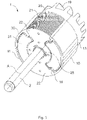
- FIG. 1 to 7 an exemplary embodiment of a rotor 1 according to the invention with 2 pairs of poles is shown.
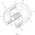
- the rotor 1 has a support body 10, as in the perspective view of FIG figure 3 shown is.
- the rotor 1 has a rotor lamination arrangement 20 made of stacked electrical laminations 21 which is accommodated in the carrier body 10 .
- the electrical laminations 21 each consist of a substantially round central annular portion 25 with two integrally connected wing-like laminations 22 which extend radially outwards to diametrically opposite sides.
- the two sheet metal segments 22 each span the same radian measure ⁇ 3.
- Pocket-like receiving spaces 30 for receiving magnet segments 31 are located between the carrier body 10 and the respective sheet metal segments 22 of the rotor sheet metal arrangement 20.
- the carrier body 10 has two holding segments 11 in the form of a partial cylinder jacket. These are located mirror-symmetrically opposite one another in relation to a central plane running through the central axis A and have hook-like projections 16 which extend radially inwards.
- the projections are provided with a rib structure of ribs 17 arranged next to one another and cavities 18 lying between them.
- the sleeve element 14 described below has a comparable framework structure.
- the respective inner surface 11i of the two holding segments 11 in the form of part cylinder jackets delimits the receiving space 30 for the respective magnet segment 31 and accordingly represents a contact surface for fixing the respective magnet segment 31.
- the retaining segments 11 which are partially in the shape of a cylinder jacket, are arranged around the central axis of the rotor and are connected to a cylindrical plate part 13 at one of their axial ends 12 .
- a hollow-cylindrical sleeve member 14 which forms a receptacle for a rotor shaft 2, which in the figure 1 is shown as an example.
- the sleeve element 14 has a rib structure consisting of a multiplicity of ribs 17 arranged next to one another, between which recesses 18 are provided.
- the carrier body 10 has two elastically and plastically deformable ribs 15 which protrude into the receiving space 30 and against which the magnet segments 31 rest. During assembly of the magnet segments 31, these ribs 15 have been elastically deformed, so that the magnet segments 31 are elastically fixed in their position.
- the support body 10 further integrally has a plurality of cooling fins 19 projecting from the plate member 13. As shown in FIG. A weight element can also be molded onto the plate part 13 in order to thereby eliminate possible imbalances.
- the selected shape of the magnet segments 30 on their end faces 33 viewed in the circumferential direction is good in the figure 7 to recognize.
- a step is provided in each case, with which the magnet segment 30 rests against the projection 16 formed on the carrier body.
Landscapes
- Engineering & Computer Science (AREA)
- Power Engineering (AREA)
- Permanent Field Magnets Of Synchronous Machinery (AREA)
- Iron Core Of Rotating Electric Machines (AREA)
Description
- Die Erfindung betrifft einen verbesserten Rotor für einen Elektromotor.
- Die im Stand der Technik bekannten Rotoren weisen diverse Nachteile auf. So besteht regelmäßig ein Bedürfnis danach den Magnetmaterialanteil zu reduzieren ohne nachteilige Auswirkungen betreffend dem erforderlichen magnetischen Fluss zu haben.
- Daneben kommt es immer wieder vor, dass Magnete (bei Permanentmagnetrotoren) brechen oder Risse bekommen und dann nicht mehr ihre Funktion erfüllen, da sie sich nicht mehr in ihrer bestimmungsgemäßen Position befinden.
- Ein grundsätzlicher Bedarf besteht im Hinblick auf die Erleichterung der Magnetisierung und bei der Erhöhung der Variabilität des magnetischen Flussverlaufs.
- Rotoren für einen Elektromotor, welche in Radialrichtung begrenzte Aufnahmeräume aufweisen, sind beispielsweise aus den Schriften
EP 3 334 012 A1 ,WO 92/09132 A1 WO 91/09443 A1 US 2013/162090 A1 undUS 2011/057523 A1 gelehrt. - Der Erfindung liegt deshalb die Aufgabe zugrunde, vorbesagte Aspekte zu verbessern und ein neuartiges Konstruktionskonzept für einen in den besagten Eigenschaften optimierten Rotor vorzuschlagen.
- Diese Aufgabe wird durch die Merkmalskombination gemäß Anspruch 1 gelöst.
- Erfindungsgemäß wird hierzu ein Rotor für einen Elektromotor (mit der Polpaarzahl p) gemäß Anspruch 1 vorgeschlagen. Ein solcher erfindungsgemäßer Rotor umfasst einen Trägerkörper in dem eine Rotorblechanordnung aus gestapelten Elektroblechen aufgenommen ist, welche aus jeweils einem im wesentlichen runden zentralen Ringabschnitt mit der Anzahl an p einstückig damit verbundenen flügelartigen Blechsegmenten gebildet sind (somit je Pol ein Blechsegment), wobei zwischen dem Trägerkörper und den jeweiligen Blechsegmenten der Rotorblechanordnung taschenartige Aufnahmetaschen zur Aufnahme von Magnetsegmenten (somit je Pol eine Aufnahme für ein Magnetsegment) ausgebildet sind. Die Aufnahmetaschen werden im Weiteren auch als Taschen oder Aufnahmeräume bezeichnet.
- Die Rotorblechanordnung dient als Eisenrückschlusskörper, welcher vorzugsweise in einem Spritzgusswerkzeug mit Kunststoff teilumspritzt wird, so dass entsprechend geformte Aufnahmetaschen gebildet werden, in welche die Magnetsegmente und vorzugsweise auch die Rotorwelle gefügt werden können. Bei diesem Fertigungskonzeptkann auch gleichzeitig sehr kostengünstig eine Kühlflügelgeometrie inklusive einem Wuchtausgleich mit angespritzt werden. Die Kunststoffumspritzung dient hierbei als Fixierung der Magnetsegmente und der Rotorwelle.
- Mit Vorteil ist dabei vorgesehen, dass für die Polpaarzahl p genau p taschenartige Aufnahmeräume ausgebildet sind, die in Umfangsrichtung gleichmäßig zwischen den jeweils p flügelartigen Blechsegmenten ausgebildet sind. Ein Polpaar setzt sich somit aus einem Elektroblechsegment und einem Magnetsegment (eingebracht in eine taschenförmige Aufnahme) zusammen.
- In einer vorteilhaften Ausgestaltung der Erfindung ist vorgesehen, dass der Trägerkörper zwei teilzylindermantelförmige Haltesegmente ausbildet, deren Innenfläche (innere Mantelfläche) jeweils einen Aufnahmeraum für ein Magnetsegment je eines der p Polpaare begrenzt.
- Weiter ist mit Vorteil vorgesehen, dass die teilzylindermantelförmigen Haltesegmente um die zentrale Achse des Rotors herum angeordnet sind und mit ihrem einen axialen Ende an einem zylinderförmigen Plattenteil des Trägerkörpers verbunden sind.
- In einer weiteren vorteilhaften Ausgestaltung der Erfindung ist vorgesehen, dass der Trägerkörper ferner um seine zentrale Achse herum ein hohlzylinderförmiges Hülsenelement besitzt, welches eine Aufnahme für eine Rotorwelle ausbildet.
- Ebenfalls von Vorteil ist eine Gestaltung, bei der der Trägerkörper jeweils in den Aufnahmeraum hineinragende elastisch und/oder plastisch verformbare Haltemittel ausbildet, gegen die ein vollständig in den Aufnahmeraum jeweils eingeführtes Magnetsegment kraftschlüssig anliegt. Als Toleranzausgleich bei der Fixierung werden entsprechende Rippenstrukturen oder Haltestrukturen eingebracht, um die bei der Herstellung von Dauermagneten üblichen Toleranzen auszugleichen. Die Magnetsegmente werden dabei in die vorgesehenen Tasche gefügt, wobei die Rippen zu einem Teil abgeschabt oder deformiert werden und/oder elastisch verformt werden.
- Ein weiteres vorteilhaftes Konzept sieht vor, dass die genannten teilzylindermantelförmigen Haltesegmente jeweils zwei radial nach innen zur zentralen Achse des Rotors gerichtete Vorsprünge, Nasen oder Auskragungen aufweisen, von denen sich jeweils in den Aufnahmeraum hineinragende elastisch und/oder plastisch verformbare Haltemittel weg erstrecken.
- Weiter vorteilhaft ist es, wenn die besagten Haltemittel als eine sich in Axialrichtung des Rotors erstreckende Rippenstruktur aus einer oder mehreren parallel verlaufenden Halterippen gebildet sind.
- In einer besonders vorteilhaften Ausführung ist vorgesehen, dass jeder Pol (bestehend aus Magnetsegment und Elektroblechsegment und ggf. Zwischenräume) ein ganz bestimmtes Bogenmaß aufspannt. Hierzu wird vorgeschlagen, dass die jeweiligen Magnetsegmente eines der p Polpaare jeweils als ein Teilringabschnitt mit einem Bogenwinkel von α2 ausgebildet sind, wobei für α2 folgendes gilt: 0,4*α1 ≤ α2 ≤ 0,7*α1 und α1=360/p. Weiter ist vorgesehen, dass die jeweiligen flügelartigen Blechsegmente jeweils in Umfangsrichtung einen Teilringabschnitt mit einem Bogenwinkel von α3 ausbilden, wobei für α3 folgendes gilt: 0,25*α1 ≤ α3 ≤ 0,5*α1.
- Es hat sich weiter als vorteilhaft erwiesen, wenn der Trägerkörper ferner eine Mehrzahl an Kühlflügel integral aufweist. Auf diese Weise kann dieser gleichzeitig zu seiner Fixier- und Positionierfunktion auch noch eine Kühlfunktion übernehmen.
- Zur Optimierung der Positionierung und zum Abfangen von Zentripetalkräften der Magnetsegmenten, besitzen diese an ihren in Umfangsrichtung betrachteten Stirnseiten je eine Stufe oder Schulter, mit der sie jeweils gegen einen am Trägerkörper ausgebildeten Vorsprung anliegen.
- Weiterhin ist zum Abfangen auftretender dynamischer Lasten und Kräfte ein Konzept vorgesehen, bei dem der Trägerkörper zumindest abschnittsweise, aus einer Rippenstruktur oder Fachwerkstruktur gebildet wird und zwar aus nebeneinander angeordneten Rippen oder Zähnen und jeweils paarweise dazwischen liegenden Ausnehmungen oder Hohlräumen. Mit Vorteil ist vorgesehen, dass die Rippenstruktur oder Fachwerkstruktur zumindest im Bereich der Vorsprünge und/oder dem zylindrischen Hülsenelement vorgesehen ist.
- Durch das beschriebene Konzept ist es möglich durch den Trägerkörper auch gerissene Magnetsegmente in exakter Position zu fixieren und ein unerwünschtes Verschieben zu verhindern.
- Ferner können Magnetsegmente vormagnetisiert und in diesem Zustand montiert werden, indem diese einfach in die Aufnahmetaschen eingeschoben werden.
- Andere vorteilhafte Weiterbildungen der Erfindung sind in den Unteransprüchen gekennzeichnet bzw. werden nachstehend zusammen mit der Beschreibung der bevorzugten Ausführung der Erfindung anhand der Figuren näher dargestellt.
- Es zeigen:
- Fig. 1
- eine perspektivische Ansicht eines Ausführungsbeispiels eines Rotors,
- Fig. 2
- eine Seitenansicht des Rotors aus
Figur 1 , - Fig. 3
- eine perspektivische Ansicht eines Trägerkörpers des Rotors aus
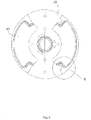
Figur 1 , - Fig. 4
- eine stirnseitige Ansicht auf den Trägerkörper aus
Fig. 3 , - Fig. 5
- eine stirnseitige Ansicht auf den Trägerkörper aus
Fig. 3 mit eingefügten Magnetsegmenten, - Fig. 6
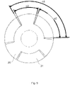
- das Detail B aus
Figur 4 , - Fig. 7
- das Detail C aus
Figur 5 , - Fig. 8
- drei Ausführungsbeispiele von Anordnungen mit unterschiedlichen Bogenmaßen der Magnetsegmente und Blechpaketsegmente bei einer Ausführung mit 4 Polen (p = 2),
- Fig. 9, 10
- drei Ausführungsbeispiele von Anordnungen mit unterschiedlichen Bogenmaßen der Magnetsegmente und Blechpaketsegmente bei einer Ausführung mit 6 Polen (p = 3) und
- Fig. 11,12
- zwei nicht erfindungsgmäße Beispiele e von Anordnungen mit unterschiedlichen Bogenmaßen der Magnetsegmente und Blechpaketsegmente bei einer Ausführung mit 6 Polen (p = 3) mit einer alternativen Magnetanordnung.
- Im Folgenden wird die Erfindung mit Bezug auf die
Figuren 1 bis 12 näher erläutert, wobei gleiche Bezugszeichen in den Figuren auf gleiche strukturelle und/oder funktionale Merkmale hinweisen. - In den
Figuren 1 bis 7 ist eine beispielhafte Ausführungsform eines erfindungsgemäßen Rotors 1 mit 2 Polpaaren gezeigt. Der Rotor 1 besitzt einen Trägerkörper 10, wie dieser in der perspektivischen Ansicht derFigur 3 dargestellt ist. - Ferner besitzt der Rotor 1 eine Rotorblechanordnung 20 aus gestapelten Elektroblechen 21, die in dem Trägerkörper 10 aufgenommen ist. Die Elektroblechen 21 bestehen aus jeweils einem im wesentlichen runden zentralen Ringabschnitt 25 mit zwei einstückig damit verbundenen flügelartigen Blechsegmenten 22, die sich radial nach außen zu diametral gegenüberliegenden Seiten hin erstrecken. Die beiden Blechsegmente 22 spannen dabei jeweils ein gleiches Bogenmaß α3 auf.
- Zwischen dem Trägerkörper 10 und den jeweiligen Blechsegmenten 22 der Rotorblechanordnung 20 befinden sich taschenartige Aufnahmeräume 30 zur Aufnahme von Magnetsegmenten 31.
- Wie in der
Figur 3 gut ersichtlich, besitzt der Trägerkörper 10 zwei teilzylindermantelförmige Haltesegmente 11. Diese liegen sich bezogen auf eine durch die zentrale Achse A verlaufenden Mittelebene spiegelsymmetrisch gegenüber und besitzen hakenartige Vorsprünge 16, die sich nach radial Innen erstrecken. - Die Vorsprünge sind mit einer Rippenstruktur aus nebeneinander angeordneten Rippen 17 und dazwischen liegenden Hohlräumen 18 versehen. Eine vergleichbare Fachwerkstruktur besitzt das nachfolgend noch beschriebene Hülsenelement 14.
- Die jeweilige Innenfläche 11i der beiden teilzylindermantelförmigen Haltesegmente 11 begrenzt den Aufnahmeraum 30 für das jeweilige Magnetsegment 31 und stellt demnach eine Anlagefläche zum Fixieren des jeweiligen Magnetsegments 31 dar.
- Die teilzylindermantelförmigen Haltesegmente 11 sind um die zentrale Achse des Rotors herum angeordnet und mit ihrem einen axialen Ende 12 an einem zylinderförmigen Plattenteil 13 verbunden. An diesem Plattenteil 13 des Trägerkörpers 10 ist ferner um die zentrale Achse herum ein hohlzylinderförmiges Hülsenelement 14 vorgesehen, welches eine Aufnahme für eine Rotorwelle 2 ausbildet, die in der
Figur 1 beispielhaft gezeigt ist. Das Hülsenelement 14 besitzt eine Rippenstruktur bestehend aus einer Vielzahl nebeneinander angeordneter Rippen 17 zwischen denen Aussparungen 18 vorgesehen sind. - Mit Hilfe der Detailansichten der
Figuren 6 und7 lässt sich das Fixieren der toleranzbehafteten Magnetsegmente 31 erläutern. Der Trägerkörper 10 besitzt hierzu jeweils zwei in den Aufnahmeraum 30 hineinragende elastisch und plastisch verformbare Rippen 15 gegen die die Magnetsegmente 31 anliegen. Bei der Montage der Magnetsegmente 31 sind diese Rippen 15 elastisch verformt worden, so dass die Magnetsegmente 31 elastisch in ihrer Position fixiert sind. - Der Trägerkörper 10 besitzt ferner integral eine Mehrzahl an Kühlflügel 19, die von dem Plattenteil 13 wegstehen. An das Plattenteil 13 kann ferner ein Gewichtselement angespritzt werden, um dadurch mögliche Unwuchten zu beseitigen.
- Die gewählte Form der Magnetsegmente 30 an ihren in Umfangsrichtung betrachteten Stirnseiten 33 ist gut in der
Figur 7 zu erkennen. Hierzu ist je eine Stufe vorgesehen, mit der das Magnetsegment 30 jeweils gegen den am Trägerkörper ausgebildeten Vorsprung 16 anliegt. - In der
Figur 8 sind drei Ausführungsbeispiele von Anordnungen mit unterschiedlichen Bogenmaßen α2 der Magnetsegmente 31 und Bogenmaßen α3 der Blechpaketsegmente 22 gezeigt (siehe nachfolgende Tabelle 1). Das Bogenmaß wird dabei am äußeren radialen Rand gemessen. Das Bogenmaß α1 hat immer den Wert α1 = 360°/p.Tabelle 1 Ansicht der Figur 8 Bogenmaß α2 Bogenmaß α3 1. Ausführungsbeispiel Linke Ansicht 0,45 × 180° 0,41 × 180° 2. Ausführungsbeispiel Mittlere Ansicht 0,55 × 180° 0,34 × 180° 3. Ausführungsbeispiel Rechte Ansicht 0,65 × 180° 0,26 × 180° - In den
Figuren 9 und10 sind drei weitere Ausführungsbeispiele von Anordnungen mit unterschiedlichen Bogenmaßen der Magnetsegmente 31 und Blechpaketsegmente 22 bei einer Ausführung mit 6 Polen (p = 3) gezeigt, wobei folgende Zusammenhänge bestehen (siehe Tabelle 2).Tabelle 2 Ansicht der Figur 10 Bogenmaß α2 Bogenmaß α3 1. Ausführungsbeispiel Linke Ansicht 0,475 × 120° 0,475 × 120° 2. Ausführungsbeispiel Mittlere Ansicht 0,575 × 120° 0,375 × 120° 3. Ausführungsbeispiel Rechte Ansicht 0,675 × 120° 0,275 × 120° - In den
Figuren 11 und12 sind zwei nicht erfindungsgemäße Beispiele von Anordnungen mit unterschiedlichen Breiten der Magnetsegmente 31 und Blechpaketsegmente 22 bei einer Ausführung mit 6 Polen (p = 3) gezeigt, wobei folgende Zusammenhänge bestehen (siehe Tabelle 3). Der Trägerkörper 10 ist dabei in denFiguren 11 und12 nicht dargestellt.Tabelle 3 Ansicht der Figur 12 Bogenmaß α3 1. Ausführungsbeispiel Linke Ansicht 0,214 × 120° 2. Ausführungsbeispiel rechte Ansicht 0,364 × 120° - Die Erfindung beschränkt sich in ihrer Ausführung nicht auf die vorstehend angegebenen bevorzugten Ausführungsbeispiele. Vielmehr ist eine Anzahl von Varianten denkbar, welche von der dargestellten Lösung auch bei grundsätzlich anders gearteten Ausführungen Gebrauch . macht, entsprechend dem Umfang der Ansprüche.
Claims (14)
- Rotor (1) für einen Elektromotor mit der Polpaarzahl p umfassend einen Trägerkörper (10) in dem eine Rotorblechanordnung (20) aus gestapelten Elektroblechen (21) aufgenommen ist, welche aus jeweils einem im Wesentlichen runden zentralen Ringabschnitt mit der Anzahl an p einstückig damit verbundenen flügelartigen Blechsegmenten (22) gebildet sind, welche jeweils einen Pol ausbilden, dadurch gekennzeichnet, dass zwischen dem Trägerkörper (10) und den jeweiligen Blechsegmenten (22) der Rotorblechanordnung (20) Aufnahmetaschen (30) zur Aufnahme von Magnetsegmenten (31) ausgebildet sind, welche durch den Trägerkörper (10) in Radialrichtung nach außen und in Axialrichtung einseitig begrenzt sind, so dass die Magnetsegmente (31) in die Auf nahmetaschen (30) eingeschoben werden können.
- Rotor (1) nach Anspruch 1, dadurch gekennzeichnet, dass für die Polpaarzahl p genau p Aufnahmetaschen (30) ausgebildet sind, die in Umfangsrichtung gleichmäßig zwischen den jeweils p flügelartigen Blechsegmenten (22) ausgebildet sind.
- Rotor (1) nach Anspruch 1, dadurch gekennzeichnet, dass der Trägerkörper (10) zwei teilzylindermantelförmige Haltesegmente (11) ausbildet, deren Innenfläche (11i) jeweils eine Aufnahmetasche (30) für ein Magnetsegment (31) je eines der p Polpaare begrenzt.
- Rotor (1) nach einem der vorhergehenden Ansprüche 3, dadurch gekennzeichnet, dass die teilzylindermantelförmigen Haltesegmente (11) um die zentrale Achse (A) herum angeordnet sind und mit ihrem einen axialen Ende (12) an einem zylinderförmigen Plattenteil (13) verbunden sind.
- Rotor (1) nach einem der vorhergehenden Ansprüche 1 bis 4, dadurch gekennzeichnet, dass der Trägerkörper (10) ferner um die zentrale Achse (A) herum ein hohlzylinderförmiges Hülsenelement (14) besitzt, welches eine Aufnahme für eine Rotorwelle (2) ausbildet.
- Rotor (1) nach einem der vorhergehenden Ansprüche, dadurch gekennzeichnet, dass der Trägerkörper (10) jeweils in den Aufnahmetasche (30) hinein ragende elastisch und/oder plastisch verformbare Haltemittel (15) ausbildet, gegen die jeweils ein vollständig in die Aufnahmetasche (30) eingeführtes Magnetsegment (31) kraftschlüssig anliegt.
- Rotor (1) nach einem der vorhergehenden Ansprüche 3 bis 6, dadurch gekennzeichnet, dass die teilzylindermantelförmigen Haltesegmente (11) jeweils zwei radial nach innen zur zentralen Achse (A) hin gerichtete Vorsprünge (16) aufweisen, von denen sich jeweils in die Aufnahmetasche (30) hineinragende elastisch und/oder plastisch verformbare Haltemittel (15) weg erstrecken.
- Rotor (1) nach Anspruch 6 oder 7, dadurch gekennzeichnet, dass die Haltemittel (15) als eine sich in Axialrichtung des Rotors erstreckende Rippenstruktur aus einer oder mehreren parallel verlaufenden Halterippen gebildet sind.
- Rotor (1) nach einem der vorhergehenden Ansprüche, dadurch gekennzeichnet, dass die jeweiligen Magnetsegmente (30) eines der p Polpaare jeweils als ein Teilringabschnitt mit einem Bogenwinkel von α2 ausgebildet sind, wobei 0,4*α1 ≤ α2 ≤ 0,7*α1 mit p=2 und α1=360/p.
- Rotor (1) nach einem der vorhergehenden Ansprüche, dadurch gekennzeichnet, dass die jeweiligen flügelartigen Blechsegmente (22) jeweils in Umfangsrichtung einen Teilringabschnitt mit einem Bogenwinkel von α3 ausbilden, wobei 0,25*α1 ≤ α3 ≤ 0,5*α1, wobei p=2 und α1=360/p.
- Rotor (1) nach einem der vorhergehenden Ansprüche, dadurch gekennzeichnet, dass der Trägerkörper (10) eine Mehrzahl an Kühlflügeln (19) integral aufweist.
- Rotor (1) nach einem der vorhergehenden Ansprüche, dadurch gekennzeichnet, dass die Magnetsegmente (30) an ihren in Umfangsrichtung betrachteten Stirnseiten (33) je eine Stufe oder Schulter aufweisen, mit der sie jeweils gegen einen am Trägerkörper (10) ausgebildeten Vorsprung (16) anliegen.
- Rotor (1) nach einem der vorhergehenden Ansprüche, dadurch gekennzeichnet, dass der Trägerkörper (10) zumindest abschnittsweise, aus einer Rippenstruktur oder Fachwerkstruktur gebildet ist, welche aus nebeneinander angeordneten Rippen (17) oder Zähnen und dazwischenliegenden Ausnehmungen oder Hohlräumen (18) besteht.
- Rotor (1) nach Anspruch 5, 7 und 13, dadurch gekennzeichnet, dass zumindest die Vorsprünge (16) und/oder das zylindrische Hülsenelement (14) abschnittsweise durch die Rippenstruktur oder Fachwerkstruktur gebildet werden/wird.
Applications Claiming Priority (1)
| Application Number | Priority Date | Filing Date | Title |
|---|---|---|---|
| DE102019117432.5A DE102019117432A1 (de) | 2019-06-27 | 2019-06-27 | Rotor für einen Elektromotor |
Publications (2)
| Publication Number | Publication Date |
|---|---|
| EP3758193A1 EP3758193A1 (de) | 2020-12-30 |
| EP3758193B1 true EP3758193B1 (de) | 2022-10-26 |
Family
ID=70680360
Family Applications (1)
| Application Number | Title | Priority Date | Filing Date |
|---|---|---|---|
| EP20173840.8A Active EP3758193B1 (de) | 2019-06-27 | 2020-05-11 | Rotor für einen elektromotor |
Country Status (3)
| Country | Link |
|---|---|
| EP (1) | EP3758193B1 (de) |
| CN (1) | CN210898673U (de) |
| DE (1) | DE102019117432A1 (de) |
Family Cites Families (9)
| Publication number | Priority date | Publication date | Assignee | Title |
|---|---|---|---|---|
| FR2476930A1 (fr) * | 1980-02-26 | 1981-08-28 | Jeumont Schneider | Rotor a aimants permanents interpolaires pour machine dynamoelectrique |
| US5191256A (en) * | 1989-12-15 | 1993-03-02 | American Motion Systems | Interior magnet rotary machine |
| WO1992009131A1 (en) * | 1990-11-20 | 1992-05-29 | Seiko Epson Corporation | Rotor of brushless motor |
| CN102013780B (zh) * | 2009-09-07 | 2014-03-12 | 德昌电机(深圳)有限公司 | 微型无刷电机 |
| US8981611B2 (en) * | 2011-10-28 | 2015-03-17 | Asmo Co., Ltd. | Rotor and motor |
| CN103178631B (zh) * | 2011-12-26 | 2017-08-08 | 德昌电机(深圳)有限公司 | 电机转子 |
| JP2015008259A (ja) * | 2013-05-28 | 2015-01-15 | アスモ株式会社 | ロータの製造方法及びロータの製造装置 |
| DE102014202572A1 (de) * | 2014-02-12 | 2015-08-13 | BSH Hausgeräte GmbH | Elektrischer Antriebsmotor, Pumpe und Haushaltsgerät mit einer solchen Pumpe |
| DE102016014526A1 (de) * | 2016-12-07 | 2018-06-07 | Wilo Se | Permanentmagnetrotor für eine elektrische Maschine |
-
2019
- 2019-06-27 DE DE102019117432.5A patent/DE102019117432A1/de not_active Withdrawn
- 2019-08-09 CN CN201921286871.9U patent/CN210898673U/zh active Active
-
2020
- 2020-05-11 EP EP20173840.8A patent/EP3758193B1/de active Active
Also Published As
| Publication number | Publication date |
|---|---|
| EP3758193A1 (de) | 2020-12-30 |
| CN210898673U (zh) | 2020-06-30 |
| DE102019117432A1 (de) | 2020-12-31 |
Similar Documents
| Publication | Publication Date | Title |
|---|---|---|
| DE69310627T2 (de) | Rotor eines synchronmotors | |
| DE60309811T2 (de) | Elektromotor mit Dauermagnetläufer | |
| DE69216587T2 (de) | Rotor synchroner drehmaschinen | |
| DE112013006500B4 (de) | Drehender elektrischer Mechanismus der Permanentmagnetbauart | |
| EP3913771A1 (de) | Elektromotor | |
| EP3672028B1 (de) | Rotorblech, rotor und elektrische maschine sowie verfahren zur herstellung eines rotors | |
| DE202012000842U1 (de) | Rotor für eine rotierende elektrische Maschine und Elektromotor | |
| DE102012100158A1 (de) | Stator für drehende elektrische Maschinen und Verfahren zum Herstellen desselben | |
| DE4033454A1 (de) | Permanentmagnetrotor | |
| DE102018215864A1 (de) | Rotor eines Elektromotors sowie Elektromotor | |
| DE112013006518T5 (de) | Elektrische Rotationsmaschine vom Permanentmagnet-Typ | |
| DE112017005282T5 (de) | Rotor für rotierende elektrische Maschine | |
| DE112017004455T5 (de) | Rotor für rotierende elektrische maschine und verfahren zum herstellen einer rotierenden elektrischen maschine | |
| EP2022157A1 (de) | Verfahren zur herstellung eines stators und zugehöriger stator | |
| DE20115098U1 (de) | Stator mit einer radialen Wicklung | |
| DE112006001929T5 (de) | Rotornabe und -baugruppe für eine Permanentmagnet-Elektromaschine | |
| DE102017201438A1 (de) | Blechpaketscheibe mit einer Mehrzahl von Blechpaketscheibensegmenten sowie Rotor | |
| EP2399333B1 (de) | Rotoranordnung für einen elektromotor | |
| DE202019103563U1 (de) | Rotor für einen Elektromotor | |
| WO2014180875A2 (de) | Spulenträger für eine statorwicklung eines elektromotors | |
| EP3076520B1 (de) | Rotor für eine elektrische maschine und herstellungsverfahren | |
| DE102019123433A1 (de) | Rotorblechpaket für einen Rotor und Verfahren zur Herstellung eines Rotorblechpakets | |
| DE102005060118A1 (de) | Rotor für einen elektrischen Motor | |
| WO2016162137A1 (de) | Rotoranordnung für eine elektromaschine | |
| EP3208912A1 (de) | Läufer |
Legal Events
| Date | Code | Title | Description |
|---|---|---|---|
| PUAI | Public reference made under article 153(3) epc to a published international application that has entered the european phase |
Free format text: ORIGINAL CODE: 0009012 |
|
| STAA | Information on the status of an ep patent application or granted ep patent |
Free format text: STATUS: THE APPLICATION HAS BEEN PUBLISHED |
|
| AK | Designated contracting states |
Kind code of ref document: A1 Designated state(s): AL AT BE BG CH CY CZ DE DK EE ES FI FR GB GR HR HU IE IS IT LI LT LU LV MC MK MT NL NO PL PT RO RS SE SI SK SM TR |
|
| AX | Request for extension of the european patent |
Extension state: BA ME |
|
| STAA | Information on the status of an ep patent application or granted ep patent |
Free format text: STATUS: REQUEST FOR EXAMINATION WAS MADE |
|
| 17P | Request for examination filed |
Effective date: 20210615 |
|
| RBV | Designated contracting states (corrected) |
Designated state(s): AL AT BE BG CH CY CZ DE DK EE ES FI FR GB GR HR HU IE IS IT LI LT LU LV MC MK MT NL NO PL PT RO RS SE SI SK SM TR |
|
| REG | Reference to a national code |
Ref country code: DE Ref legal event code: R079 Ref document number: 502020001881 Country of ref document: DE Free format text: PREVIOUS MAIN CLASS: H02K0001270000 Ipc: H02K0001274600 |
|
| RIC1 | Information provided on ipc code assigned before grant |
Ipc: H02K 9/22 20060101ALI20220502BHEP Ipc: H02K 1/2746 20220101AFI20220502BHEP |
|
| GRAP | Despatch of communication of intention to grant a patent |
Free format text: ORIGINAL CODE: EPIDOSNIGR1 |
|
| STAA | Information on the status of an ep patent application or granted ep patent |
Free format text: STATUS: GRANT OF PATENT IS INTENDED |
|
| INTG | Intention to grant announced |
Effective date: 20220620 |
|
| GRAS | Grant fee paid |
Free format text: ORIGINAL CODE: EPIDOSNIGR3 |
|
| GRAA | (expected) grant |
Free format text: ORIGINAL CODE: 0009210 |
|
| STAA | Information on the status of an ep patent application or granted ep patent |
Free format text: STATUS: THE PATENT HAS BEEN GRANTED |
|
| AK | Designated contracting states |
Kind code of ref document: B1 Designated state(s): AL AT BE BG CH CY CZ DE DK EE ES FI FR GB GR HR HU IE IS IT LI LT LU LV MC MK MT NL NO PL PT RO RS SE SI SK SM TR |
|
| REG | Reference to a national code |
Ref country code: GB Ref legal event code: FG4D Free format text: NOT ENGLISH |
|
| REG | Reference to a national code |
Ref country code: CH Ref legal event code: EP |
|
| REG | Reference to a national code |
Ref country code: DE Ref legal event code: R096 Ref document number: 502020001881 Country of ref document: DE |
|
| REG | Reference to a national code |
Ref country code: AT Ref legal event code: REF Ref document number: 1527780 Country of ref document: AT Kind code of ref document: T Effective date: 20221115 |
|
| REG | Reference to a national code |
Ref country code: IE Ref legal event code: FG4D Free format text: LANGUAGE OF EP DOCUMENT: GERMAN |
|
| REG | Reference to a national code |
Ref country code: LT Ref legal event code: MG9D |
|
| REG | Reference to a national code |
Ref country code: NL Ref legal event code: MP Effective date: 20221026 |
|
| PG25 | Lapsed in a contracting state [announced via postgrant information from national office to epo] |
Ref country code: NL Free format text: LAPSE BECAUSE OF FAILURE TO SUBMIT A TRANSLATION OF THE DESCRIPTION OR TO PAY THE FEE WITHIN THE PRESCRIBED TIME-LIMIT Effective date: 20221026 |
|
| PG25 | Lapsed in a contracting state [announced via postgrant information from national office to epo] |
Ref country code: SE Free format text: LAPSE BECAUSE OF FAILURE TO SUBMIT A TRANSLATION OF THE DESCRIPTION OR TO PAY THE FEE WITHIN THE PRESCRIBED TIME-LIMIT Effective date: 20221026 Ref country code: PT Free format text: LAPSE BECAUSE OF FAILURE TO SUBMIT A TRANSLATION OF THE DESCRIPTION OR TO PAY THE FEE WITHIN THE PRESCRIBED TIME-LIMIT Effective date: 20230227 Ref country code: NO Free format text: LAPSE BECAUSE OF FAILURE TO SUBMIT A TRANSLATION OF THE DESCRIPTION OR TO PAY THE FEE WITHIN THE PRESCRIBED TIME-LIMIT Effective date: 20230126 Ref country code: LT Free format text: LAPSE BECAUSE OF FAILURE TO SUBMIT A TRANSLATION OF THE DESCRIPTION OR TO PAY THE FEE WITHIN THE PRESCRIBED TIME-LIMIT Effective date: 20221026 Ref country code: FI Free format text: LAPSE BECAUSE OF FAILURE TO SUBMIT A TRANSLATION OF THE DESCRIPTION OR TO PAY THE FEE WITHIN THE PRESCRIBED TIME-LIMIT Effective date: 20221026 Ref country code: ES Free format text: LAPSE BECAUSE OF FAILURE TO SUBMIT A TRANSLATION OF THE DESCRIPTION OR TO PAY THE FEE WITHIN THE PRESCRIBED TIME-LIMIT Effective date: 20221026 |
|
| PG25 | Lapsed in a contracting state [announced via postgrant information from national office to epo] |
Ref country code: RS Free format text: LAPSE BECAUSE OF FAILURE TO SUBMIT A TRANSLATION OF THE DESCRIPTION OR TO PAY THE FEE WITHIN THE PRESCRIBED TIME-LIMIT Effective date: 20221026 Ref country code: PL Free format text: LAPSE BECAUSE OF FAILURE TO SUBMIT A TRANSLATION OF THE DESCRIPTION OR TO PAY THE FEE WITHIN THE PRESCRIBED TIME-LIMIT Effective date: 20221026 Ref country code: LV Free format text: LAPSE BECAUSE OF FAILURE TO SUBMIT A TRANSLATION OF THE DESCRIPTION OR TO PAY THE FEE WITHIN THE PRESCRIBED TIME-LIMIT Effective date: 20221026 Ref country code: IS Free format text: LAPSE BECAUSE OF FAILURE TO SUBMIT A TRANSLATION OF THE DESCRIPTION OR TO PAY THE FEE WITHIN THE PRESCRIBED TIME-LIMIT Effective date: 20230226 Ref country code: HR Free format text: LAPSE BECAUSE OF FAILURE TO SUBMIT A TRANSLATION OF THE DESCRIPTION OR TO PAY THE FEE WITHIN THE PRESCRIBED TIME-LIMIT Effective date: 20221026 Ref country code: GR Free format text: LAPSE BECAUSE OF FAILURE TO SUBMIT A TRANSLATION OF THE DESCRIPTION OR TO PAY THE FEE WITHIN THE PRESCRIBED TIME-LIMIT Effective date: 20230127 |
|
| P01 | Opt-out of the competence of the unified patent court (upc) registered |
Effective date: 20230521 |
|
| REG | Reference to a national code |
Ref country code: DE Ref legal event code: R097 Ref document number: 502020001881 Country of ref document: DE |
|
| PG25 | Lapsed in a contracting state [announced via postgrant information from national office to epo] |
Ref country code: SM Free format text: LAPSE BECAUSE OF FAILURE TO SUBMIT A TRANSLATION OF THE DESCRIPTION OR TO PAY THE FEE WITHIN THE PRESCRIBED TIME-LIMIT Effective date: 20221026 Ref country code: RO Free format text: LAPSE BECAUSE OF FAILURE TO SUBMIT A TRANSLATION OF THE DESCRIPTION OR TO PAY THE FEE WITHIN THE PRESCRIBED TIME-LIMIT Effective date: 20221026 Ref country code: EE Free format text: LAPSE BECAUSE OF FAILURE TO SUBMIT A TRANSLATION OF THE DESCRIPTION OR TO PAY THE FEE WITHIN THE PRESCRIBED TIME-LIMIT Effective date: 20221026 Ref country code: DK Free format text: LAPSE BECAUSE OF FAILURE TO SUBMIT A TRANSLATION OF THE DESCRIPTION OR TO PAY THE FEE WITHIN THE PRESCRIBED TIME-LIMIT Effective date: 20221026 Ref country code: CZ Free format text: LAPSE BECAUSE OF FAILURE TO SUBMIT A TRANSLATION OF THE DESCRIPTION OR TO PAY THE FEE WITHIN THE PRESCRIBED TIME-LIMIT Effective date: 20221026 |
|
| PG25 | Lapsed in a contracting state [announced via postgrant information from national office to epo] |
Ref country code: SK Free format text: LAPSE BECAUSE OF FAILURE TO SUBMIT A TRANSLATION OF THE DESCRIPTION OR TO PAY THE FEE WITHIN THE PRESCRIBED TIME-LIMIT Effective date: 20221026 Ref country code: AL Free format text: LAPSE BECAUSE OF FAILURE TO SUBMIT A TRANSLATION OF THE DESCRIPTION OR TO PAY THE FEE WITHIN THE PRESCRIBED TIME-LIMIT Effective date: 20221026 |
|
| PLBE | No opposition filed within time limit |
Free format text: ORIGINAL CODE: 0009261 |
|
| STAA | Information on the status of an ep patent application or granted ep patent |
Free format text: STATUS: NO OPPOSITION FILED WITHIN TIME LIMIT |
|
| 26N | No opposition filed |
Effective date: 20230727 |
|
| PG25 | Lapsed in a contracting state [announced via postgrant information from national office to epo] |
Ref country code: SI Free format text: LAPSE BECAUSE OF FAILURE TO SUBMIT A TRANSLATION OF THE DESCRIPTION OR TO PAY THE FEE WITHIN THE PRESCRIBED TIME-LIMIT Effective date: 20221026 |
|
| REG | Reference to a national code |
Ref country code: CH Ref legal event code: PL |
|
| PG25 | Lapsed in a contracting state [announced via postgrant information from national office to epo] |
Ref country code: MC Free format text: LAPSE BECAUSE OF FAILURE TO SUBMIT A TRANSLATION OF THE DESCRIPTION OR TO PAY THE FEE WITHIN THE PRESCRIBED TIME-LIMIT Effective date: 20221026 |
|
| REG | Reference to a national code |
Ref country code: BE Ref legal event code: MM Effective date: 20230531 |
|
| PG25 | Lapsed in a contracting state [announced via postgrant information from national office to epo] |
Ref country code: MC Free format text: LAPSE BECAUSE OF FAILURE TO SUBMIT A TRANSLATION OF THE DESCRIPTION OR TO PAY THE FEE WITHIN THE PRESCRIBED TIME-LIMIT Effective date: 20221026 Ref country code: LU Free format text: LAPSE BECAUSE OF NON-PAYMENT OF DUE FEES Effective date: 20230511 Ref country code: LI Free format text: LAPSE BECAUSE OF NON-PAYMENT OF DUE FEES Effective date: 20230531 Ref country code: CH Free format text: LAPSE BECAUSE OF NON-PAYMENT OF DUE FEES Effective date: 20230531 |
|
| REG | Reference to a national code |
Ref country code: IE Ref legal event code: MM4A |
|
| PG25 | Lapsed in a contracting state [announced via postgrant information from national office to epo] |
Ref country code: IE Free format text: LAPSE BECAUSE OF NON-PAYMENT OF DUE FEES Effective date: 20230511 |
|
| PG25 | Lapsed in a contracting state [announced via postgrant information from national office to epo] |
Ref country code: IE Free format text: LAPSE BECAUSE OF NON-PAYMENT OF DUE FEES Effective date: 20230511 |
|
| PG25 | Lapsed in a contracting state [announced via postgrant information from national office to epo] |
Ref country code: IT Free format text: LAPSE BECAUSE OF FAILURE TO SUBMIT A TRANSLATION OF THE DESCRIPTION OR TO PAY THE FEE WITHIN THE PRESCRIBED TIME-LIMIT Effective date: 20221026 Ref country code: FR Free format text: LAPSE BECAUSE OF NON-PAYMENT OF DUE FEES Effective date: 20230531 Ref country code: BE Free format text: LAPSE BECAUSE OF NON-PAYMENT OF DUE FEES Effective date: 20230531 |
|
| PGFP | Annual fee paid to national office [announced via postgrant information from national office to epo] |
Ref country code: DE Payment date: 20240517 Year of fee payment: 5 |
|
| PG25 | Lapsed in a contracting state [announced via postgrant information from national office to epo] |
Ref country code: BG Free format text: LAPSE BECAUSE OF FAILURE TO SUBMIT A TRANSLATION OF THE DESCRIPTION OR TO PAY THE FEE WITHIN THE PRESCRIBED TIME-LIMIT Effective date: 20221026 |
|
| PG25 | Lapsed in a contracting state [announced via postgrant information from national office to epo] |
Ref country code: BG Free format text: LAPSE BECAUSE OF FAILURE TO SUBMIT A TRANSLATION OF THE DESCRIPTION OR TO PAY THE FEE WITHIN THE PRESCRIBED TIME-LIMIT Effective date: 20221026 |
|
| GBPC | Gb: european patent ceased through non-payment of renewal fee |
Effective date: 20240511 |
|
| PG25 | Lapsed in a contracting state [announced via postgrant information from national office to epo] |
Ref country code: GB Free format text: LAPSE BECAUSE OF NON-PAYMENT OF DUE FEES Effective date: 20240511 |
|
| PGFP | Annual fee paid to national office [announced via postgrant information from national office to epo] |
Ref country code: AT Payment date: 20250721 Year of fee payment: 5 |
|
| PG25 | Lapsed in a contracting state [announced via postgrant information from national office to epo] |
Ref country code: CY Free format text: LAPSE BECAUSE OF FAILURE TO SUBMIT A TRANSLATION OF THE DESCRIPTION OR TO PAY THE FEE WITHIN THE PRESCRIBED TIME-LIMIT; INVALID AB INITIO Effective date: 20200511 |
|
| PG25 | Lapsed in a contracting state [announced via postgrant information from national office to epo] |
Ref country code: HU Free format text: LAPSE BECAUSE OF FAILURE TO SUBMIT A TRANSLATION OF THE DESCRIPTION OR TO PAY THE FEE WITHIN THE PRESCRIBED TIME-LIMIT; INVALID AB INITIO Effective date: 20200511 |
|
| REG | Reference to a national code |
Ref country code: DE Ref legal event code: R119 Ref document number: 502020001881 Country of ref document: DE |
|
| PG25 | Lapsed in a contracting state [announced via postgrant information from national office to epo] |
Ref country code: TR Free format text: LAPSE BECAUSE OF FAILURE TO SUBMIT A TRANSLATION OF THE DESCRIPTION OR TO PAY THE FEE WITHIN THE PRESCRIBED TIME-LIMIT Effective date: 20221026 |
|
| PG25 | Lapsed in a contracting state [announced via postgrant information from national office to epo] |
Ref country code: DE Free format text: LAPSE BECAUSE OF NON-PAYMENT OF DUE FEES Effective date: 20251202 |