EP3757602A1 - Electromagnetic wave detection device and information acquisition system - Google Patents
Electromagnetic wave detection device and information acquisition system Download PDFInfo
- Publication number
- EP3757602A1 EP3757602A1 EP19754546.0A EP19754546A EP3757602A1 EP 3757602 A1 EP3757602 A1 EP 3757602A1 EP 19754546 A EP19754546 A EP 19754546A EP 3757602 A1 EP3757602 A1 EP 3757602A1
- Authority
- EP
- European Patent Office
- Prior art keywords
- image forming
- electromagnetic waves
- detection apparatus
- wave detection
- electromagnetic wave
- Prior art date
- Legal status (The legal status is an assumption and is not a legal conclusion. Google has not performed a legal analysis and makes no representation as to the accuracy of the status listed.)
- Pending
Links
- 238000001514 detection method Methods 0.000 title claims abstract description 212
- 230000002250 progressing effect Effects 0.000 claims abstract description 30
- 230000003287 optical effect Effects 0.000 claims description 33
- 239000004973 liquid crystal related substance Substances 0.000 claims description 15
- 230000005540 biological transmission Effects 0.000 claims description 11
- 230000008859 change Effects 0.000 claims description 5
- RFVFQQWKPSOBED-PSXMRANNSA-N 1-myristoyl-2-palmitoyl-sn-glycero-3-phosphocholine Chemical compound CCCCCCCCCCCCCCCC(=O)O[C@@H](COP([O-])(=O)OCC[N+](C)(C)C)COC(=O)CCCCCCCCCCCCC RFVFQQWKPSOBED-PSXMRANNSA-N 0.000 claims 1
- 230000000694 effects Effects 0.000 description 12
- 230000006870 function Effects 0.000 description 11
- 238000010586 diagram Methods 0.000 description 9
- 230000005855 radiation Effects 0.000 description 5
- 238000000926 separation method Methods 0.000 description 4
- 238000002366 time-of-flight method Methods 0.000 description 4
- 238000004891 communication Methods 0.000 description 3
- 238000003384 imaging method Methods 0.000 description 3
- 238000000034 method Methods 0.000 description 2
- 238000012986 modification Methods 0.000 description 2
- 230000004048 modification Effects 0.000 description 2
- 230000007480 spreading Effects 0.000 description 2
- 238000003892 spreading Methods 0.000 description 2
- 230000009471 action Effects 0.000 description 1
- 230000008901 benefit Effects 0.000 description 1
- 230000015572 biosynthetic process Effects 0.000 description 1
- 238000000265 homogenisation Methods 0.000 description 1
- 238000002329 infrared spectrum Methods 0.000 description 1
- 238000004519 manufacturing process Methods 0.000 description 1
- 238000005259 measurement Methods 0.000 description 1
- 238000012545 processing Methods 0.000 description 1
- 230000000644 propagated effect Effects 0.000 description 1
- 238000003860 storage Methods 0.000 description 1
- 239000000758 substrate Substances 0.000 description 1
Images


Classifications
-
- G—PHYSICS
- G02—OPTICS
- G02B—OPTICAL ELEMENTS, SYSTEMS OR APPARATUS
- G02B26/00—Optical devices or arrangements for the control of light using movable or deformable optical elements
- G02B26/08—Optical devices or arrangements for the control of light using movable or deformable optical elements for controlling the direction of light
- G02B26/0816—Optical devices or arrangements for the control of light using movable or deformable optical elements for controlling the direction of light by means of one or more reflecting elements
- G02B26/0833—Optical devices or arrangements for the control of light using movable or deformable optical elements for controlling the direction of light by means of one or more reflecting elements the reflecting element being a micromechanical device, e.g. a MEMS mirror, DMD
-
- G—PHYSICS
- G01—MEASURING; TESTING
- G01S—RADIO DIRECTION-FINDING; RADIO NAVIGATION; DETERMINING DISTANCE OR VELOCITY BY USE OF RADIO WAVES; LOCATING OR PRESENCE-DETECTING BY USE OF THE REFLECTION OR RERADIATION OF RADIO WAVES; ANALOGOUS ARRANGEMENTS USING OTHER WAVES
- G01S17/00—Systems using the reflection or reradiation of electromagnetic waves other than radio waves, e.g. lidar systems
- G01S17/02—Systems using the reflection of electromagnetic waves other than radio waves
- G01S17/06—Systems determining position data of a target
- G01S17/08—Systems determining position data of a target for measuring distance only
- G01S17/10—Systems determining position data of a target for measuring distance only using transmission of interrupted, pulse-modulated waves
-
- G—PHYSICS
- G01—MEASURING; TESTING
- G01S—RADIO DIRECTION-FINDING; RADIO NAVIGATION; DETERMINING DISTANCE OR VELOCITY BY USE OF RADIO WAVES; LOCATING OR PRESENCE-DETECTING BY USE OF THE REFLECTION OR RERADIATION OF RADIO WAVES; ANALOGOUS ARRANGEMENTS USING OTHER WAVES
- G01S17/00—Systems using the reflection or reradiation of electromagnetic waves other than radio waves, e.g. lidar systems
- G01S17/87—Combinations of systems using electromagnetic waves other than radio waves
-
- G—PHYSICS
- G01—MEASURING; TESTING
- G01S—RADIO DIRECTION-FINDING; RADIO NAVIGATION; DETERMINING DISTANCE OR VELOCITY BY USE OF RADIO WAVES; LOCATING OR PRESENCE-DETECTING BY USE OF THE REFLECTION OR RERADIATION OF RADIO WAVES; ANALOGOUS ARRANGEMENTS USING OTHER WAVES
- G01S17/00—Systems using the reflection or reradiation of electromagnetic waves other than radio waves, e.g. lidar systems
- G01S17/88—Lidar systems specially adapted for specific applications
- G01S17/89—Lidar systems specially adapted for specific applications for mapping or imaging
- G01S17/894—3D imaging with simultaneous measurement of time-of-flight at a 2D array of receiver pixels, e.g. time-of-flight cameras or flash lidar
-
- G—PHYSICS
- G01—MEASURING; TESTING
- G01S—RADIO DIRECTION-FINDING; RADIO NAVIGATION; DETERMINING DISTANCE OR VELOCITY BY USE OF RADIO WAVES; LOCATING OR PRESENCE-DETECTING BY USE OF THE REFLECTION OR RERADIATION OF RADIO WAVES; ANALOGOUS ARRANGEMENTS USING OTHER WAVES
- G01S7/00—Details of systems according to groups G01S13/00, G01S15/00, G01S17/00
- G01S7/48—Details of systems according to groups G01S13/00, G01S15/00, G01S17/00 of systems according to group G01S17/00
- G01S7/481—Constructional features, e.g. arrangements of optical elements
- G01S7/4816—Constructional features, e.g. arrangements of optical elements of receivers alone
-
- G—PHYSICS
- G01—MEASURING; TESTING
- G01S—RADIO DIRECTION-FINDING; RADIO NAVIGATION; DETERMINING DISTANCE OR VELOCITY BY USE OF RADIO WAVES; LOCATING OR PRESENCE-DETECTING BY USE OF THE REFLECTION OR RERADIATION OF RADIO WAVES; ANALOGOUS ARRANGEMENTS USING OTHER WAVES
- G01S7/00—Details of systems according to groups G01S13/00, G01S15/00, G01S17/00
- G01S7/48—Details of systems according to groups G01S13/00, G01S15/00, G01S17/00 of systems according to group G01S17/00
- G01S7/481—Constructional features, e.g. arrangements of optical elements
- G01S7/4817—Constructional features, e.g. arrangements of optical elements relating to scanning
-
- G—PHYSICS
- G01—MEASURING; TESTING
- G01S—RADIO DIRECTION-FINDING; RADIO NAVIGATION; DETERMINING DISTANCE OR VELOCITY BY USE OF RADIO WAVES; LOCATING OR PRESENCE-DETECTING BY USE OF THE REFLECTION OR RERADIATION OF RADIO WAVES; ANALOGOUS ARRANGEMENTS USING OTHER WAVES
- G01S7/00—Details of systems according to groups G01S13/00, G01S15/00, G01S17/00
- G01S7/48—Details of systems according to groups G01S13/00, G01S15/00, G01S17/00 of systems according to group G01S17/00
- G01S7/483—Details of pulse systems
- G01S7/486—Receivers
- G01S7/4861—Circuits for detection, sampling, integration or read-out
- G01S7/4863—Detector arrays, e.g. charge-transfer gates
-
- H—ELECTRICITY
- H04—ELECTRIC COMMUNICATION TECHNIQUE
- H04N—PICTORIAL COMMUNICATION, e.g. TELEVISION
- H04N23/00—Cameras or camera modules comprising electronic image sensors; Control thereof
- H04N23/50—Constructional details
- H04N23/55—Optical parts specially adapted for electronic image sensors; Mounting thereof
-
- H—ELECTRICITY
- H04—ELECTRIC COMMUNICATION TECHNIQUE
- H04N—PICTORIAL COMMUNICATION, e.g. TELEVISION
- H04N23/00—Cameras or camera modules comprising electronic image sensors; Control thereof
- H04N23/56—Cameras or camera modules comprising electronic image sensors; Control thereof provided with illuminating means
-
- G—PHYSICS
- G02—OPTICS
- G02B—OPTICAL ELEMENTS, SYSTEMS OR APPARATUS
- G02B13/00—Optical objectives specially designed for the purposes specified below
- G02B13/14—Optical objectives specially designed for the purposes specified below for use with infrared or ultraviolet radiation
-
- G—PHYSICS
- G02—OPTICS
- G02B—OPTICAL ELEMENTS, SYSTEMS OR APPARATUS
- G02B17/00—Systems with reflecting surfaces, with or without refracting elements
- G02B17/08—Catadioptric systems
Definitions
- the present disclosure relates to an electromagnetic wave detection apparatus and an information acquisition system.
- DMD Digital Micromirror Device
- CCD Charge-Coupled Device
- An electromagnetic wave detection apparatus includes:
- An information acquisition system includes:
- An information acquisition system includes:
- An information acquisition system includes:
- the present disclosure relates to homogenization of the intensity of electromagnetic waves of a secondary image without enlarging an apparatus. According to the present embodiment, the intensity of electromagnetic waves of a secondary image may be homogenized.
- An electromagnetic wave detection apparatus includes a primary image forming optical system configured to form an image of electromagnetic waves incident thereon, a progression unit configured to direct electromagnetic waves having propagated from the primary image forming optical system and being incident on a reference surface in a direction different from an incident direction using each pixel, a secondary image forming optical system configured to cause a detector to form an image of electromagnetic waves formed on the reference surface by the progression unit, and the detector.
- the electromagnetic wave detection apparatus can cause the detector to detect electromagnetic waves of the secondary image.
- the progression unit does not refract electronic waves incident thereon.
- an image of electromagnetic waves formed on the reference surface progresses in a progression direction while spreading.
- the large secondary image forming optical system 19' may interfere with a primary image forming optical system 15' and complicate actual manufacture. This is due to a relatively small switching angle of the DMD, whereby an angle formed by a direction of electromagnetic waves that are progressed to the DMD from the primary image forming optical system 15' and a direction of electromagnetic waves that are progressed by the DMD is also small. As illustrated in FIG.
- the electromagnetic wave detection apparatus applying the present disclosure can suppress the spread of electromagnetic waves advancing in the progression direction from the reference surface and reduce the probability of the occurrence of vignetting caused by some pixels, without adopting a large secondary image forming optical system.
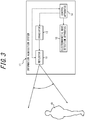
- An information acquisition system 11 that includes an electromagnetic wave detection apparatus 10 according to a first embodiment of the present disclosure includes the electromagnetic wave detection apparatus 10, an irradiator 12, a reflector 13, and a control apparatus 14, as illustrated in FIG. 3 .
- a broken line connecting functional blocks indicates a flow of a control signal or communicated information. Communication represented by a broken line may be wired communication or wireless communication. A solid line projecting from each functional block indicates a beam of electromagnetic waves.
- the electromagnetic wave detecting apparatus 10 includes a first aperture 23, a first image forming unit 15, a separator 16, a progression unit 18, a second image forming unit 19, a first detector 20, a third image forming unit 21, a second detector 22, and a third detector 17.
- the first aperture 23 defines, for example, an aperture and allows a portion of electromagnetics wave incident on the aperture to pass therethrough.
- the first aperture 23 may be, for example, an aperture stop and may function as a diaphragm for the first image forming unit 15 configured to adjust an amount of electromagnetic waves to pass therethrough.
- the first aperture 23 may be arranged at a location in the vicinity of a front focal point of the first image forming unit 15.
- the "location in the vicinity of the front focal point” is a location of the aperture where an angle formed by a principal ray of each angle of view on an image side of the first image forming unit 15 and a principal axis of the first image forming unit 15 is equal to or smaller than a predetermined value.
- the "location in the vicinity of the front focal point” is a location of the aperture where an angle formed by a principal ray of a largest angle of view on the image side of the first image forming unit 15 and the principal axis of the first image forming unit 15 is equal to or smaller than the predetermined value.
- the predetermined value may be, for example, 15°.
- the first aperture 23 may be arranged at the front focal point of the first image forming unit 15 and constitute an image side telecentric optical system, together with the first image forming unit 15.
- the first aperture 23 does not need to constitute the image side telecentric optical system, together with the first image forming unit 15.
- the first image forming unit 15 forms an image of incident electromagnetic waves from the first aperture 23.
- the first image forming unit 15 is arranged in such a manner that an angle formed by a progression axis of electromagnetic waves with each angle of view having passed through the first image forming unit 15 and a principal axis of the first image forming unit 15 is equal to or smaller than the predetermined value mentioned above.
- the first image forming unit 15 may be arranged such that the progression axis and the principal axis are parallel to each other.
- the first image forming unit 15 may be arranged such that the progression axis of incident electromagnetic waves with each angle of view sequentially pass through a center of an image forming part on a preceding stage and then an image forming part on a subsequent stage, as illustrated in FIG. 5 .
- the first image forming unit 15 may be arranged at a location opposing an aperture ap formed in a housing of the electromagnetic wave detection apparatus 10 in such a manner that an axis of the aperture ap and the principal axis are parallel to each other.
- the axis of the aperture ap is an axis of the cylinder.
- the axis of the aperture ap is a line that passes through the center of the aperture ap and is perpendicular to a wall surface of the housing surrounding the aperture ap.
- the aperture ap is different from the opening defined by the first aperture 23, the aperture ap may be the opening defined by the first aperture 23.
- the first image forming unit 15 includes, for example, at least one of a lens and a mirror.
- the first image forming unit 15 forms an image of incident electromagnetic waves that have passed through the first aperture 23 from an object ob serving as a subject.
- the fist image forming unit 15 may be a retrofocus lens system.
- the separator 16 is arranged between the first image forming unit 15 and a primary image forming location where an image of the object ob is formed by the first image forming unit 15.
- the separator 16 separates incident electromagnetic waves from the first image forming unit 15 into electromagnetic waves that progress in a progression unit direction da towards the progression unit 18 and electromagnetic waves that progress in a third progression direction d3 towards the third detector 17.
- the separator 16 may separate electromagnetic waves such that incident electromagnetic waves of a first frequency progress in the progression unit direction da and incident electromagnetic waves of a second frequency progress in the third direction d3.
- the separator 16 separates incident electromagnetic waves into electromagnetic waves that progress in the third direction d3 and electromagnetic waves that progress in the progression direction, by employing at least one of reflection, separation, and refraction.
- the separator 16 reflects some of incident electromagnetic waves in the third direction d3 and transmits other incident electromagnetic waves in the progression unit direction d3, by way of example.
- the separator 16 may transmit some of incident electromagnetic waves in the third direction d3 and reflect other incident electromagnetic waves in the progression unit direction da.
- the separator 16 may refract some of incident electromagnetic waves in the third direction d3 and transmit other incident electromagnetic waves in the progression unit direction da.
- the separator 16 may transmit some of incident electromagnetic waves in the third direction d3 and refract other incident electromagnetic waves in the progression unit direction da.
- the separator 16 may refract some of incident electromagnetic waves in the third direction d3 and refract other incident electromagnetic waves in the progression unit direction da.
- the separator 16 may include at least one of, for example, a half mirror, a beam splitter, a dichroic mirror, a cold mirror, a hot mirror, a meta surface, a deflecting element, and a prism.
- the progression unit 18 is arranged on a path of electromagnetic waves progressing in the progression unit direction da from the separator 16. Further, the progression unit 18 is arranged at or in the vicinity of the primary image forming location of the object ob in the progression unit direction da by the first image forming unit 15.
- the progression unit 18 is arranged at the primary image forming location.
- the progression unit 18 has a reference surface ss on which electromagnetic waves having passed through the first image forming unit 15 and the separator 16 are to be incident.
- the reference surface ss is composed of a plurality of pixels px arranged in a two-dimensional manner.
- the reference surface ss is a surface that causes effects such as, for example, reflection and transmission of an electromagnetic wave in at least one of a first state and a second state, which will be described later.
- the reference surface ss may be perpendicular to a central axis of electromagnetic waves that progress in the progression unit direction da from the separator 16.
- the progression unit 18 can switch each of the pixels px between the first state in which electromagnetic waves incident on the reference surface ss are caused to progress in a first direction d1 and the second state in which electromagnetic waves incident on the reference surface ss are caused to progress in a second direction d2.
- the first state is a first reflection state in which electromagnetic waves incident on the reference surface ss are reflected in the first direction d1.
- the second state is a second reflection state in which electromagnetic waves incident on the reference surface ss are reflected in the second direction d2.
- the progression unit 18 includes, in particular, a reflection surface for each of the pixels px to reflect electromagnetic waves.
- the progression unit 18 switches between the first reflection state and the second reflection state by changing an orientation of the reflection surface for each of the pixels px.
- the progression unit 18 includes, for example, a DMD (Digital Micromirror Device).
- the DMD can drive minute reflection surfaces constituting the reference surface ss such that the reflection surface for each of the pixels px is inclined at +12° or -12° with respect to the reference surface ss.
- the reference surface ss is parallel to a plate surface of the substrate having the minute reflection surfaces mounted thereon.
- the progression unit 18 switches each of the pixels px between the first state and the second state, based on control by the control apparatus 14, as will be described later.
- the progression unit 18 can simultaneously switch some of the pixels px to the first state such that electromagnetic waves incident thereon are caused to progress in the first direction d1 and switch other pixels px to the second state such that electromagnetic waves incident thereon are caused to progress in the second direction d2.
- the second image forming unit 19 is arranged in the first direction d1 from the progression unit 18.
- the second image forming unit 19 includes, for example, at least one of a lens and a mirror.
- the second image forming unit 19 may be arranged such that a principal plane thereof is inclined with respect to the reference surface ss of the progression unit 18.
- the second image forming unit 19 may be arranged such that the principal axis thereof passes through a region of the reference surface ss of the progression unit 18.
- the second image forming unit 19 may be arranged such that the principal axis thereof passes through a center of the reference surface ss, i.e., a central pixel px.
- the second image forming unit 19 forms an image of the object ob from electronic waves for which the progression direction is switched by the progression unit 18.
- the first detector 20 is arranged on a path of electromagnetic waves progressing from the second image forming unit 19 after progressing in the first direction d1 by virtue of the progression unit 18.
- the first detector 20 is arranged at or in the vicinity of a secondary image forming location where an image of electromagnetic waves formed on the reference surface ss of the progression unit 18 is formed by the second image forming unit 19.
- the first detector 20 may be arranged such that a detection surface thereof is inclined with respect to the reference surface ss, that is, such that an extension surface of the detection surface and an extension surface of the reference surface ss intersect each other.
- the first detector 20 may be arranged to incline with respect to a principal plane of the second image forming unit 19.
- the first detector 20 may be arranged such that a principal axis of the second image forming unit 19 passes through a range of the detection surface of the first detector 20. Further, the first detector 20 may be arranged such that the principal axis of the second image forming unit 19 pass through a center of the detection surface of the first detector 20.
- the first detector 20 may be arranged such that an extension surface of its detection surface intersects an extension surface of the reference surface ss and an extension surface of the principal plane of the second image forming unit 19 on a single straight line. Accordingly, the reference surface ss, the principal plane of the second image forming unit 19, and the detection surface of the first detector 20 may be arranged in a manner satisfying the Scheimpflug principle.
- the first detector 20 detects electromagnetic waves having passed through the second image forming unit 19, i.e., electromagnetic waves progressing in the first direction d1.
- the first detector 20 is a passive sensor.
- the first detector 20 includes, in particular, an element array.
- the first detector 20 including an image sensor or an imaging array captures an image of electromagnetic waves formed on the detection surface and generates image information regarding the captured object ob.
- the first detector 20 captures, in particular, an image of visible light.
- the first detector 20 generates the image information and transmits a signal representing the image information to the control apparatus 14.
- the first detector 20 may capture an image of infrared light, ultraviolet, radio waves, or the like rather than an image of visible light.
- the first detector 20 may include a distance measuring sensor. In this configuration, the electromagnetic wave detection apparatus 10 can acquire distance information in the form of an image using the first detector 20.
- the first detector 20 may include a temperature sensor or the like. In this configuration, the electromagnetic wave detection apparatus 10 can acquire temperature information in the form of an image using the first detector 20.
- the third image forming unit 21 is arranged in the second direction d2 from the progression unit 18.
- the third image forming unit 21 includes, for example, at least one of a lens and a mirror.
- the third image forming unit 21 may be arranged such that a principal plane thereof is inclined with respect to the reference surface ss of the progression unit 18.
- the third image forming unit 21 may be arranged such that its principal axis passes through a region of the reference surface ss of the progression unit 18. Further, the third image forming unit 21 may be arranged such that its principal axis passes through the center of the reference surface ss, i.e., the central pixel px.
- the third image forming unit 21 forms an image of electromagnetic waves from the object ob for which the progression direction is changed by the progression unit 18.
- the second detector 22 is arranged on the path of electromagnetic waves progressing from the third image forming unit 21 after progressing in the second direction d2 by virtue of the progression unit 18.
- the second detector 22 is arranged at or in the vicinity of the secondary image forming location where an image of electromagnetic waves formed on the reference surface ss of the progression unit 18 is formed by the third image forming unit 21.
- the second detector 22 may be arranged such that a detection surface thereof is inclined with respect to the reference surface ss, that is, such that an extension surface of the detection surface and the extension surface of the reference surface ss intersect each other.
- the second detector 22 may be arranged to incline with respect to the principal plane of the third image forming unit 21.
- the second detector 22 may be arranged such that a principal axis of the third image forming unit 21 passes through a region of the detection surface of the second detector 22. Further, the second detector 22 may be arranged such that the principal axis of the third image forming unit 21 passes through the center of the detection surface of the second detector 22.
- the second detector 22 may be arranged such that an extension surface of its detection surface intersects the extension surface of the reference surface ss and an extension surface of the third image forming unit 21 on a single straight line.
- the reference surface ss, the principal plane of the third image forming unit 21, and the detection surface of the second detector 22 may be arranged in a manner satisfying the Scheimpflug principle.
- the second detector 22 detects electromagnetic waves having passed the third image forming unit 21, i.e., electromagnetic waves progressing in the second direction d2.
- the second detector 22 is an active sensor configured to detect electromagnetic waves reflected from the target ob after being radiated toward the object ob by the irradiator 12. In the first embodiment, the second detector 22 detects electromagnetic waves that are reflected from the object ob after being radiated by the irradiator 12, reflected by the reflector 13, and then progress to the object ob. As will be described below, the electromagnetic waves radiated by the irradiator 12 are at least one of infrared light, visible light, ultraviolet, and radio waves.
- the second detector 22 is a sensor of a type that is the same as or a different from that of the first detector 20, and detects electromagnetic waves of a different type or the same type.
- the second detector 22 includes, in particular, an element constituting the distance measuring sensor.
- the second detector 22 includes an element such as an APD (Avalanche PhotoDiode), a PD (PhotoDiode), an SPAD (Single Photon Avalanche Diode), a millimeter wave sensor, a submillimeter-wave sensor, or a distance image sensor.
- the second detector 22 may include an element array such as an APD array, a PD array, an MPPC (Multi Photon Pixel Counter), a distance measuring imaging array, or a distance measuring image sensor.
- the second detector 22 transmits, as a signal, detection information indicating that electromagnetic waves reflected from the subject are detected to the control apparatus 14.
- the second detector 22 is, in particular, an infrared sensor configured to detect electromagnetic waves in the infrared spectrum.
- the second detector 22 composed of one element constituting the distance measuring sensor as described above simply needs to be able to detect electromagnetic waves and does not need to form an image on the detection surface.
- the second detector 22 does not necessarily need to be arranged at or in the vicinity of the second image forming location where an image is formed by the third image forming unit 21. That is, in this configuration, provided that electromagnetic waves from all angles of view can be incident on the detection surface of the second detector 22, the second detector 22 may be arranged at any location on the path of electromagnetic waves progressing from the third image forming unit 21 after progressing in the progression unit direction da by virtue of the progression unit 18.
- the third detector 17 is arranged on the path of electromagnetic waves that progress in the third direction d3 from the separator 16. Further, the third detector 17 is arranged at or in the vicinity of the image forming location of the object ob by the first image forming unit 15 in the third direction d3 from the separator 16. The third detector 17 detects electromagnetic waves progressing in the third direction d3 from the separator 16.
- the third detector 17 is a passive sensor.
- the third detector 17 includes, in particular, an element array.
- the third detector 17 includes an image sensor or an imaging array and is configured to capture an image of electromagnetic waves formed on the detection surface and generate image information regarding the captured object ob.
- the third detector 17 captures, in particular, an image of visible light.
- the third detector 17 transmits, as a signal, the generated image information to the control apparatus 14.
- the third detector 17 may capture an image of infrared light, ultraviolet, or radio waves, other than an image of visible light.
- the third detector 17 may include a distance measuring sensor.
- the electromagnetic wave detecting apparatus 10 can acquire distance information in the form of an image using the third detector 17.
- the third detector 17 may include a distance measuring sensor, a temperature sensor, or the like. In this configuration, the electromagnetic wave detecting apparatus 10 can acquire temperature information in the form of an image using the third detector 17.
- the irradiator 12 radiates at least one of infrared light, visible light, ultraviolet, and radio waves. In the first embodiment, the irradiator 12 radiates infrared light. The irradiator 12 irradiates the object ob with electromagnetic waves, directly or indirectly via the reflector 13. In the first embodiment, the irradiator 12 irradiates the object ob with electromagnetic waves indirectly via the reflector 13.
- the irradiator 12 radiates a narrow beam of electromagnetic waves having a beam spread of, for example, 0.5°.
- the irradiator 12 can radiate an electromagnetic wave in pulses.
- the irradiator 12 includes an LED (Light Emitting Diode) or an LD (Laser Diode).
- the irradiator 12 switches between radiating and not radiating electromagnetic waves, based on control by the control apparatus 14.
- the reflector 13 changes an irradiation location of electromagnetic waves which irradiate the object ob by reflecting electromagnetic waves radiated from the irradiator 12 while changing the direction thereof. That is, the reflector 13 scans the object ob using electromagnetic waves radiated from the irradiator 12.
- the second detector 22 constitutes a scanning type distance measuring sensor, together with the reflector 13.
- the reflector 13 scans the object ob in a one-dimension or in two-dimensions. In the first embodiment, the reflector 13 scans the object ob in two-dimensions.
- the reflector 13 is configured such that at least a portion of an irradiation region of electromagnetic waves that are radiated from the irradiator 12 and reflected by the reflector 13 is included in a detection region of electromagnetic waves in the electromagnetic wave detection apparatus 10. Thus, at least some of electromagnetic waves radiated to the object ob via the reflector 13 can be detected by the electromagnetic wave detection apparatus 10.
- the reflector 13 is configured such that at least a portion of the irradiation region of electromagnetic waves that is radiated from the irradiator 12 and reflected by the reflector 13 is included in a detection region of the second detector 22. In the first embodiment, thus, at least some of electromagnetic waves radiated to the object ob via the reflector 13 can be detected by the second detector 22.
- the reflector 13 includes, for example, a MEMS (Microelectromechanical systems) mirror, a polygon mirror, a galvanometer mirror, or the like. In the first embodiment, the reflector 13 includes the MEMS mirror.
- MEMS Microelectromechanical systems
- the reflector 13 changes a reflection direction of electromagnetic waves, based on control by the control apparatus 14, which will be described later.
- the reflector 13 may include an angle sensor such as, for example, an encoder and notify the control apparatus 14 of an angle detected by the angle sensor as direction information used for reflecting electromagnetic waves.
- the control apparatus 14 can calculate the irradiation location, based on the direction information acquired from the reflector 13.
- the control apparatus 14 can calculate the irradiation location, based on a driving signal input to cause the reflector 13 to change the reflection direction of electromagnetic waves.
- the control apparatus 14 includes one or more processors and a memory.
- the processor may include a general purpose processor configured to read a specific program and perform a specific function, or a specialized processor dedicated for specific processing.
- the specialized processor may include an ASIC (Application Specific Integrated Circuit).
- the processor may include a PLD (Programmable Logic Device).
- the PLD may include an FPGA (Field-Programmable Gate Array).
- the control apparatus 14 may include at least one of a SoC (System-on-a-Chip) that includes one or more cooperating processors or a SiP (System in a Package).
- the control apparatus 14 acquires information regarding the surroundings of the electromagnetic wave detection apparatus 10, based on electromagnetic waves respectively detected by the first detector 20, the second detector 22, and the third detector 17.
- the information regarding the surroundings is, for example, image information, distance information, temperature information, or the like.
- the control apparatus 14 acquires electromagnetic waves detected as an image by the first detector 20 or the third detector 17 serving as the image information, as described above.
- the control apparatus 14 acquires the distance information regarding the irradiation location irradiated by the irradiator 12 using a ToF (Time-of-Flight) method, which will be described later, based on the detection information detected by the second detector 22.
- ToF Time-of-Flight
- the control apparatus 14 causes the irradiator 12 to emit electromagnetic waves in pulses by inputting an electromagnetic wave radiation signal to the irradiator 12 (see “ELECTROMAGNETIC WAVE RADIATION SIGNAL” field).
- the irradiator 12 emits electromagnetic waves, based on the electromagnetic wave radiation signal (see "IRRADIATOR RADIATION AMOUNT” field).
- the electromagnetic waves that have been radiated by the irradiator 12, reflected by the reflector 13, irradiate any irradiation region are reflected in the irradiation region.
- the control apparatus 14 changes at least some of the pixels px within an image formation region of the progression unit 18 for an image of the reflected wave from the irradiation region formed by the first image forming unit 15 to the first state, and changes other pixels px to the second state. Then, when the first detector 20 detects electromagnetic waves reflected from the irradiation region (see "ELECTROMAGNETIC WAVE DETECTION AMOUNT" field), the first detector 20 notifies the control apparatus 14 of the detection information, as described above.
- the control apparatus 14 includes, for example, a time measuring LSI (Large Scale Integrated circuit) and measures a time ⁇ T from a time T1 at which the control apparatus 14 causes the irradiator 12 to radiate electromagnetic waves to a time T2 at which the detection information is acquired (see "ACQUISITION OF DETECTION INFORMATION").
- the control apparatus 14 calculates a distance to the irradiation location by multiplying the time ⁇ T by the speed of light and then dividing an acquired value by 2.
- the control apparatus 14 calculates the irradiation location, based on the direction information acquired from the reflector 13 or the driving signal input to the reflector 13 by the control apparatus 14, as described above.
- the control apparatus 14 calculates a distance to an irradiation location while changing the irradiation location, and thus generates the distance information in the form of an image.
- the information acquisition system 11 is configured to generate the distance information employing a Direct ToF technique that directly measures the time period for radiated electromagnetic waves to return, as described above.
- the information acquisition system 11 is not limited to this configuration.
- the information acquisition system 11 may be configured to generate the distance information employing a Flash ToF technique that radiates electromagnetic waves in a constant cycle and indirectly measures the time period for the electromagnetic waves to return, based on a phase difference between the radiated electromagnetic waves and returned electromagnetic waves.
- the information acquisition system 11 may generate the distance employing another ToF technique such as, for example, a Phased ToF technique.
- the electromagnetic wave detecting apparatus 10 of the first embodiment configured as described above causes electromagnetic waves incident on the first image forming unit 15 to be incident on the reference surface ss of the progression unit 18, and the angle formed by the progression angle of each angle of view of the first image forming unit 15 and the principal axis of the first image forming unit 15 is equal to or smaller than the predetermined value.
- a principal ray of each angle of view at the first image forming unit 15 has relatively small spread from the principal axis, as illustrated in FIG. 7 . Accordingly, the electromagnetic wave detection apparatus 10 can suppress the spread of electromagnetic waves that progress toward the second image forming unit 19 and the third image forming unit 21 from the reference surface ss.
- the electromagnetic wave detection apparatus 10 can avoid enlargement of the second image forming unit 19 and the third image forming unit 21 that cause electromagnetic waves incident on the progression unit 18 to be incident thereon without causing vignetting.
- the electromagnetic wave detection apparatus 10 can homogenize the intensity of electromagnetic waves of the secondary images formed by the second image forming unit 19 and the third image forming unit 21, without enlarging the electromagnetic wave detection apparatus 10 in its entirety.
- Such configuration and effect are applicable also to an electromagnetic wave detection apparatus according to a second embodiment, which will be described later.
- the first aperture 23 and the first image forming unit 15 are arranged to constitute the image-side telecentric optical system.
- the electromagnetic wave detecting apparatus 10 having this configuration enables minimization of the spread of electromagnetic waves that progress in the progression unit direction da from the reference surface ss. Accordingly, the electromagnetic wave detection apparatus 10 can homogenize the intensity of electromagnetic waves of the secondary images formed by the second image forming unit 19 and the third image forming unit 21 while avoiding enlargement of the electromagnetic wave detection apparatus 10 in its entirety.
- Such configuration and effect are applicable also to the electromagnetic wave detection apparatus according to the second embodiment, which will be described later.
- the progression unit 18, the second image forming unit 19, and the first detector 20 are arranged such that the extension surface of the reference surface ss and the extension surface of the detection surface of the first detector 20 intersect each other and the principal axis of the second image forming unit 19 passes through the reference surface ss and the detection surface of the first detector 20.
- a configuration different from the electromagnetic wave detection apparatus 10 of the first embodiment a configuration illustrated in FIG.
- a principal plane of a primary image forming optical system 15"' for forming an image of electromagnetic waves on a reference surface of a progression unit 18"', a reference surface of the progression unit 18"', a principal plane of a secondary image forming optical system 19"', and a detection surface of a detector 20'" are parallel to one another.
- a range of an angle of view of the secondary image forming optical system 19'" spaced apart from the principal axis is used for detection.
- a resolution in a range of an angle of view spaced apart from a principal axis of an image forming system is lower than that of around the principal axis.
- the first embodiment has the above configuration in which the reference surface ss of the progression unit 18, the principal plane of the second image forming unit 19, and the detection surface of the first detector 20 can be arranged in a manner so as to satisfy the Scheimpflug principle. Accordingly, in the electromagnetic wave detection apparatus 10, even when the second image forming unit 19 is deviated from the location opposing the progression unit 18, an image of electromagnetic waves in the vicinity of the principal axis of the second image forming unit 19 associated with an image formed by the first image forming unit 15 on the reference surface ss can be included in the detection surface of the first detector 20 and formed. Thus, the electromagnetic wave detection apparatus 10 can improve the resolution of the image of electromagnetic waves detected by the first detector 20. Such configuration and effect are applicable also to the electromagnetic wave detection apparatus according to the second embodiment, which will be described later.
- the principal axis of the second image forming unit 19 passes through the center of the reference surface ss and the center of the detection surface of the first detector 20.
- the electromagnetic wave detection apparatus 10 having this configuration can cause an image of electromagnetic waves in a region close to the principal axis of the second image forming unit 19 to be preferentially included in the detection surface of the first detector 20 and formed.
- the electromagnetic wave detection apparatus 10 can maximize the resolution of the image of electromagnetic waves detected by the first detector 20.
- Such configuration and effect are applicable also to the electromagnetic wave detection apparatus according to the second embodiment, which will be described later.
- the extension surface of the reference surface ss, the extension surface of the principal plane of the second image forming unit 19, and the extension surface of the detection surface of the first detector 20 intersect one another on the same straight line.
- the reference surface ss of the progression unit 18, the principal plane of the second image forming unit 19, and the detection surface of the first detector 20 satisfy the Scheimpflug principle. Accordingly, the electromagnetic wave detection apparatus 10 reliably improves the resolution of the image of electromagnetic waves detected by the first detector 20.
- Such configuration and effect are applicable also to the electromagnetic wave detection apparatus according to the second embodiment, which will be described later.
- electromagnetic waves can be switched between the first state and the second state for each of the pixels px.
- the electromagnetic wave detection apparatus 10 having this configuration can cause the principal axis of the first image forming unit 15 to coincide with the principal axis of the second image forming unit 19 in the first direction d1 in which electromagnetic waves are caused to progress in the first state and the principal axis of the third image forming unit 21 in the second direction d2 in which electromagnetic waves are caused to progress in the second state.
- the electromagnetic wave detection apparatus 10 can suppress a deviation between the principal axis of the first detector 20 and the principal axis of the second detector 22 by switching the pixels px of the progression unit 18 to one of the first state and the second state.
- the electromagnetic wave detection apparatus 10 can suppress a deviation between coordinate systems in a detection result by the first detector 20 and a detection result by the second detector 22.
- Such configuration and effect are applicable also to the electromagnetic wave detection apparatus according to the second embodiment, which will be described later.
- the electromagnetic wave detection apparatus 10 of the first embodiment includes the third image forming unit 21 and the second detector 22.
- the electromagnetic wave detection apparatus 10 having this configuration can enable the second detector 22 to detect information based on electromagnetic waves from each portion of the object ob that reflects electromagnetic waves to be incident on each of the pixels px. Such configuration and effect are applicable also to the electromagnetic wave detection apparatus according to the second embodiment, which will be described later.
- the progression unit 18, the third image forming unit 21, and the second detector 22 are arranged such that the extension surface of the reference surface ss, the extension surface of the principal plane of the third image forming unit 21, and the extension surface of the detection surface of the second detector 22 intersect one another on the same straight line.
- This configuration enables the arrangement of the reference surface ss, the principal plane of the third image forming unit 21, and the detection surface of the second detector 22 that satisfies the Scheimpflug principle.
- the electromagnetic wave detection apparatus 10 even when the third image forming unit 21 is deviated from the location opposing the progression unit 18, an image of electromagnetic waves in the vicinity of the principal axis of the third image forming unit 21 may be detected on the detection surface of the second detector 22. Accordingly, the electromagnetic wave detection apparatus 10 can improve the resolution of the image of electromagnetic waves detected by the second detector 22.
- electromagnetic waves progressing from the first image forming unit 15 are separated into electromagnetic waves progressing in the progression unit direction da and electromagnetic waves progressing in the third direction d3.
- the electromagnetic wave detection apparatus 10 having this configuration can cause the principal axis of the first image forming unit 15 to coincide with the central axis of electromagnetic waves caused to progress in the progression unit direction da and the central axis of electromagnetic waves caused to progress in the third direction d3.
- the electromagnetic wave detection apparatus 10 can suppress a deviation between the coordinate systems of the first detector 20 and the second detector 22 and the coordination system of the third detector 17.
- Such configuration and effect are applicable also to the electromagnetic wave detection apparatus according to the second embodiment, which will be described later.
- the electromagnetic wave detection apparatus 10 of the first embodiment includes the third detector 17.
- the electromagnetic wave detection apparatus 10 having this configuration can separately detect electromagnetic waves of an image the same as the image formed by the first detector 20. Such configuration and effect are applicable also to the electromagnetic wave detection apparatus according to the second embodiment, which will be described later.
- the first image forming unit 15 is a retrofocus lens system.
- the first image forming unit 15 has a short focal length and a long flange focal distance.
- the electromagnetic wave detection apparatus 10 can reduce the probability of interference between electromagnetic waves progressing in the first direction d1 or the second direction d2 by the progression unit 18 and the first image forming unit 15, while employing the first image forming unit 15 having a wide angle.
- the control apparatus 14 acquires the information regarding the surroundings of the electromagnetic wave detection apparatus 10, based on electromagnetic waves respectively detected by the first detector 20, the second detector 22, and the third detector 17.
- the information acquisition system 11 having this configuration can provide useful information based on detected electromagnetic waves.
- the electromagnetic wave detection apparatus according to the second embodiment of the present disclosure will be described.
- the orientations of the progression unit and the third detector with respect to the first image forming unit are different from those of the first embodiment, and the locations and the orientations of the third image forming unit and the second detector with respect to the progression unit are different from those of the first embodiment.
- the second embodiment will be described focusing on aspects different from the first embodiment. Note that elements having the same configurations of the elements of the first embodiment will be denoted by the same reference signs.
- An electromagnetic wave detection apparatus 100 includes the first aperture 23, a first image forming unit 150, the separator 16, a progression unit 180, the second image forming unit 19, the first detector 20, a third image forming unit 210, a second detector 220, and a third detector 170, as illustrated in FIG. 10 .
- the information acquisition system 11 of the second embodiment has the same configuration as that of the first embodiment, except for the configuration of the electromagnetic wave detection apparatus 100.
- the configurations and functions of the first aperture 23, the separator 16, the second image forming unit 19, and the first detector 20 are the same as those of the first embodiment.
- the first image forming unit 150 can be arranged such that a principal axis thereof is inclined with respect to the axis of the aperture ap and, simultaneously, passes through the aperture ap, in a manner different from the first embodiment.
- the configuration and the function of the first image forming unit 150 are the same as those of the first image forming unit 150 of the first embodiment.
- the progression unit 180 may be arranged in a manner different from the first embodiment, such that the reference surface ss is inclined with respect to a virtual plane vp on which a principal axis of the first image forming unit 150 extends, that is, such that an extension surface of the virtual plane vp and an extension surface of the reference surface ss intersect each other.
- the virtual plane vp may be a plane that is spaced apart from the first image forming unit 150 by a predetermined distance and perpendicular to the axis of the aperture ap.
- the predetermined distance is a distance to an object surface from the first image forming unit 150 that is located at a predetermined distance from the progression unit 180 and uses the reference surface ss as an image surface.
- the progression unit 180 may be arranged such that an extension surface of the principal plane of the first image forming unit 150 and an extension surface of the reference surface ss of the progression unit 180 intersect each other, that is, such that the reference surface ss is inclined with respect to the principal plane of the first image forming unit 150.
- such an inclined arrangement in which the reference surface ss is inclined with respect to the principal plane of the first image forming unit 150 means, in a case in which the separator 16 refracts the electromagnetic waves into the progression unit direction da for the separation, an inclined arrangement in which the reference surface ss of the progression unit 180 rotated about the location of the separator 16 by an amount ("angle of incidence” - "refraction angle") in a direction opposite to the refraction is inclined with respect to the principal plane of the first image forming unit 150.
- such an inclined arrangement in which the reference surface ss is inclined with respect to the principal plane of the first image forming unit 150 means, in a case in which the separation in the progression unit direction da by the separator 16 is performed by reflection, an inclined arrangement in which the reference surface ss in a plane-symmetrical orientation with respect to the reflection surface of the separator 16 is inclined with respect to the principal plane of the first image forming unit 150.
- the progression unit 180 may be arranged such that the principal axis of the first image forming unit 150 passes within a region of the reference surface ss of the progression unit 180. Further, the progression unit 180 may be arranged such that the principal axis of the first image forming unit 150 passes the center of the reference surface ss of the progression unit 180.
- the progression unit 180 may be arranged such that the extension surface of the reference surface ss intersect the principal plane of the first image forming unit 150 and the virtual plane vp on one straight line.
- the principal plane of the first image forming unit 150, the reference surface ss, and the virtual plane vp are arranged in a manner so as to satisfy the Scheimpflug principle.
- the progression unit 180 may be arranged such that the second direction d2 in which the progression unit 180 causes progression is perpendicular to the reference surface ss.
- the configuration and the function of the progression unit 180 other than the orientation described above are the same as the progression unit 18 of the first embodiment.
- the second image forming unit 19 may be arranged in the first direction d1 in which the progression unit 180 causes progression such that the principal plane thereof is inclined with respect to the reference surface ss of the progression unit 180, in a manner similar to the first embodiment.
- Other arrangement conditions, configurations, and functions of the second image forming unit 19 of the second embodiment are the same as the second image forming unit 19 of the first embodiment.
- the first detector 20 is arranged at or in the vicinity of the secondary image forming location of the second image forming unit 19 for an image of electromagnetic waves formed on the reference surface ss of the progression unit 180, in a manner similar to the first embodiment.
- the first detector 20 may be arranged in a manner similar to the first embodiment, such that the extension surface of the detection surface of the first detector 20 intersects the extension surface of the reference surface ss and the extension surface of the principal plane of the second image forming unit 19 on one straight line.
- the reference surface ss, the principal plane of the second image forming unit 19, and the detection surface of the first detector 20 may be arranged in a manner so as to satisfy the Scheimpflug principle, in a manner similar to the first embodiment.
- Other arrangement conditions, configurations, and functions of the first detector 20 of the second embodiment are the same as the first detector 20 of the first embodiment.
- the third image forming unit 210 may be arranged such that the principal plane thereof is parallel to the reference surface ss of the progression unit 180, in a manner different from the first embodiment.
- Other arrangement conditions, configurations, and functions of the third image forming unit 210 of the second embodiment are the same as the third image forming unit 21 of the first embodiment.
- the second detector 220 may be arranged such that the detection surface thereof is perpendicular to the principal axis of the third image forming unit 210, in a manner different from the first embodiment.
- Other arrangement conditions, configurations, and functions of the second detector 220 of the second embodiment are the same as the second detector 22 of the first embodiment.
- the third detector 170 may be arranged such that the extension surface of the first image forming unit 150 and the extension surface of the detection surface of the third detector 170 intersect each other, in a manner different from the first embodiment. That is, the detection surface may be arranged to incline with respect to the principal plane of the first image forming unit 150.
- such an inclined arrangement of the detection surface inclined with respect to the principal plane of the first image forming unit 150 means, in a case in which the separator 16 separates electromagnetic waves in the third direction d3 by refraction, an inclined arrangement in which the detection surface of the third detector 170 rotated about the location of the separator 16 by the amount ("angle of incidence” - "refraction angle") in a direction opposite to the refraction is inclined with respect to the principal plane of the first image forming unit 150.
- such an inclined arrangement of the detection surface inclined with respect to the principal plane of the first image forming unit 150 means, in a case in which the separator 16 reflects the electromagnetic waves into the third direction d3 for the separation, an inclined arrangement in which the detection surface in a plane-symmetry orientation with respect to the reflection surface of the separator 16 is inclined with respect to the principal plane of the first image forming unit 150.
- the third detector 170 and the first image forming unit 150 may be arranged such that the extension surface of the principal plane of the first image forming unit 150 and the extension surface of the detection surface of the third detector 170 intersect each other on the virtual plane vp.
- the principal plane of the first image forming unit 150, the detection surface of the third detector 170, and the virtual plane vp may be arranged in a manner so as to satisfy the Scheimpflug principle.
- Other arrangement conditions, configurations, and functions of the third detector 170 of the second embodiment are the same as the third detector 17 of the first embodiment.
- This configuration enables the arrangement in which the object surface located at the predetermined distance from the first image forming unit 150, the principal plane of the first image forming unit 150, the reference surface ss of the progression unit 180, the principal plane of the second image forming unit 19, and the detection surface of the first detector 20 satisfy the Scheimpflug principle.
- the electromagnetic wave detection apparatus 100 is configured such that the first image forming unit 150 is not arranged at the location opposing the progression unit 180, an image of electromagnetic waves of an object in the vicinity of the principal axis formed by the first image forming unit 150 on the virtual plane vp, on which the principal axis of the first image forming unit 150 passes, can be included in the reference surface ss and formed.
- the third image forming unit 210 may be arranged at the location opposing the progression unit 180.
- the third image forming unit 210 can be arranged in such a manner that the reference surface ss of the progression unit 180 and the principal plane of the third image forming unit 210 are parallel to each other and, simultaneously, the principal axis of the third image forming unit 210 passes within the reference surface ss of the progression unit 180.
- an image in a range of an angle of view in the vicinity of the principal axis of the third image forming unit 210 may be formed by the second detector 220.
- a resolution of an image of electromagnetic waves detected by the second detector 220 can be improved.
- the principal axis of the first image forming unit 150 passes through the center of the reference surface ss.
- the electromagnetic wave detection apparatus 100 having this configuration can cause an image of electromagnetic waves in a region close to the principal axis of the first image forming unit 150 to be incident on the reference surface ss of the progression unit 180.
- the electromagnetic wave detection apparatus 100 can propagate the image of the electromagnetic waves in the region close to the principal axis of the first image forming unit 150 to the first detector 20 and the second detector 220. Accordingly, the electromagnetic wave detection apparatus 100 can maximize a resolution of an image of the electromagnetic waves detected by the first detector 20 and the second detector 220.
- the extension surface of the reference surface ss of the progression unit 180 and the extension surface of the principal plane of the first image forming unit 150 intersect each other on the same straight line.
- the electromagnetic wave detecting apparatus 100 having this configuration enables the arrangement in which the reference surface ss of the progression unit 180 and the principal plane of the first image forming unit 150 satisfy the Scheimpflug principle. Accordingly, the electromagnetic wave detection apparatus 100 can further improve a resolution of an image of electromagnetic waves detected by the first detector 20 and the second detector 220.
- the electromagnetic wave detection apparatuses 10 and 100 may include at least one of them, e.g., the control apparatus 14 as a controller.
- progression unit 18 of the first embodiment and the progression unit 180 of the second embodiment can change the progression direction of electromagnetic waves incident on the reference surface ss between the two directions: the second direction d1 and the second direction d2, the progression units 18 and 180 may be able to change the progression direction between three or more directions, rather than two directions.
- first state of the progression units 18 and 180 of the first and second embodiments refers the first reflection state for reflecting electromagnetic waves incident on the reference surface ss in the first direction d1
- second state refers the second reflection state for reflecting electromagnetic waves incident on the reference surface ss in the second direction d2
- these states may refer to other conditions.
- the first state may refer a passing state in which electromagnetic waves incident on the reference surface ss are caused to pass and progress in the first direction d1.
- each of the progression units 18 and 180 may include a shutter that is provided for each of the pixels px and has a reflection surface for reflecting electromagnetic waves in the second direction d2.
- the progression units 18 and 180 having this configuration can switch between the passing state or the transmission state serving as the first state and the reflection state serving as the second state, by opening or closing the shutter for each of the pixels px.
- the progression units 18 and 180 having such a configuration may include, for example, a MEMS shutter in which a plurality of shutters capable of opening and closing are arranged in an array on a plane.
- each of the progression units 18 and 181 may include a liquid crystal shutter that can be switched between the reflection state for reflecting electromagnetic waves and the transmission state for transmitting electromagnetic waves, in accordance with a liquid crystal alignment.
- the progression units 18 and 181 having this configuration can switch between the transmission state serving as the first state and the reflection state serving as the second state for each of the pixels px by switching the liquid crystal alignment for each of the pixels px.
- the information acquisition system 11 has the configuration in which the reflector 13 scans a beam of an electromagnetic wave radiated by the irradiator 12, and the second detectors 22 and 220 function as scanning type active sensors in cooperation with the reflector 13.
- the information acquisition system 11 is not limited to this configuration. An effect similar to the first embodiment can be obtained by, for example, the information acquisition system 11 in which the reflector 13 is omitted and the irradiator 12 radiates electromagnetic waves and information is acquired without scanning.
- the information acquisition system 11 has the configuration in which the first detector 20 and the third detectors 17 and 170 serve as passive sensors, and the second detector 220 serves as an active sensor.
- the information acquisition system 11 is not limited to this configuration. An effect similar to the first and second embodiments can be obtained by, for example, the information acquisition system 11 in which the first detector 20, the second detectors 22 and 220, and the third detectors 17 and 170 all serve as active sensors or passive sensors, or one of them serves as a passive sensor.
- the first aperture and the first image forming unit are arranged to form an image side telecentric optical system.
- At least one of an arrangement in which the principal axis of the second image forming unit passes through a center of the reference surface and a center of the detection surface of the first detector and an arrangement in which the principal axis of the first image forming unit passes through the center of the reference surface is satisfied.
- At least one of an arrangement in which an extension surface of the reference surface, an extension surface of a principal plane of the second image forming unit, and an extension surface of the detection surface of the first detector intersect one another on the same straight line and an arrangement in which the extension surface of the reference surface and an extension surface of the principal plane of the first image forming unit intersect each other is satisfied.
- the progression unit can switch each of the pixels between a first state in which incident electromagnetic waves from the first image forming unit are caused to progress in the first direction and a second state in which electromagnetic waves are caused to progress in a second direction.
- the electromagnetic wave detection apparatus further includes:
- the extension surface of the reference surface, an extension surface of a principal plane of the third image forming unit, and an extension surface of a detection surface of the second detector are arranged to intersect one another on the same straight line.
- the reference surface, the principal plane of the third image forming unit, and the detection surface of the second detector are arranged to satisfy the Scheimpflug principle.
- the progression unit includes a reflection surface for each of the pixels and can change an orientation of the reflection surface for each of the pixels.
- the progression unit switches each of the pixels between the first state and the second state by changing an orientation of the reflection surface for each of the pixels.
- the progression unit includes a digital micromirror device in which a plurality of mirrors are arranged in a plane, and switches each of the pixels between the first state and the second state by changing an orientation of each of the mirrors of the digital micromirror device for each of the pixels.
- the progression unit includes a reflection surface for each of the pixels and can open and close the reflection surface for each of the pixels.
- the progression unit switches each of the pixels between the first state and the second state by opening and closing the reflection surface for each of the pixels.
- the progression unit includes a MEMS shutter in which a plurality of shutters capable of opening and closing the reflection surface for each of the pixels are arranged in a plane, and switches each of the pixels between the first state and the second state by opening and closing each of the shutters of the MEMS shutter.
- the progression unit can switch each of the pixels between a reflection state for reflecting electromagnetic waves and a transmission state for transmitting electromagnetic waves, in accordance with a liquid crystal alignment.
- the progression unit switches each of the pixels between the first state and the second state by switching each of the pixels between the reflection state and the transmission state in accordance with the liquid crystal alignment.
- the progression unit includes a liquid crystal shutter capable of switching between the reflection state and the transmission state in accordance with the liquid crystal alignment and switches each of the pixels between the first state and the second state by changing the liquid crystal alignment of the liquid crystal shutter.
- the first detector includes at least one of a PD, an APD, an SPAD, an MPPC, an image sensor, an infrared sensor, a millimeter wave sensor, a submillimeter wave sensor, a distance measuring image sensor, a distance measuring sensor, and a temperature sensor.
- the first detector detects at least one of infrared light, visible light, ultraviolet, and radio waves.
- the second detector includes a sensor of a type that is the same as or different from that of the first detector.
- the electromagnetic wave detection apparatus further includes a separator for separating incident electromagnetic waves from the first image forming unit into electromagnetic waves progressing toward the progression unit and electromagnetic waves progressing in a third direction.
- the separator separates incident electromagnetic waves from the first image forming unit such that electromagnetic waves in a first frequency progress toward the progression unit and electromagnetic waves in a second frequency progress in the third direction.
- the separator separates incident electromagnetic waves employing at least one of reflection, transmission, and refraction, such that electromagnetic waves progress toward the progression unit and in the third direction.
- the separator transmits some incident electromagnetic waves toward the progression unit and reflects other electromagnetic waves in the third direction.
- the separator reflects some incident electromagnetic waves toward the progression unit and transmits other electromagnetic waves in the third direction.
- the separator transmits some incident electromagnetic waves toward the progression unit and refracts other electromagnetic waves in the third direction.
- the separator refracts some incident electromagnetic waves toward the progression unit and transmits other electromagnetic waves in the third direction.
- the separator refracts some incident electromagnetic waves toward the progression unit and refracts other electromagnetic waves in the third direction.
- the separator includes at least one of a half mirror, a beam splitter, a dichroic mirror, a cold mirror, a hot mirror, a meta surface, a deflection element, and a prism.
- the electromagnetic wave detection apparatus further includes a third detector configured to detect electromagnetic waves progressing in the third direction.
- the first image forming unit is a retrofocus lens system.
- the electromagnetic wave detection apparatus further includes a controller configured to acquire information regarding the surroundings, based on electromagnetic waves detected by the first detector.
- the electromagnetic wave detection apparatus further includes a controller configured to acquire information regarding the surroundings, based on electromagnetic waves detected by the second detector.
- the electromagnetic wave detection apparatus further includes a controller configured to acquire information regarding the surroundings, based on electromagnetic waves detected by the third detector.
Abstract
Description
- This application claims priority to and the benefit of Japanese Patent Applications No.
2018-027323 filed on February 19, 2018 2018-109593 filed on June 7, 2018 - The present disclosure relates to an electromagnetic wave detection apparatus and an information acquisition system.
- Devices such as a DMD (Digital Micromirror Device) that include an element for changing a progression direction of electromagnetic waves incident on each pixel are known. For example, an apparatus that forms a primary image of an object on a surface of a DMD and then forms a secondary image of the primary image formed on the surface of the DMD on a surface of a CCD (Charge-Coupled Device) via a lens is known (see PTL 1 set forth below).
- PTL 1:
JP 3507865 B2 - An electromagnetic wave detection apparatus according to a first aspect includes:
- a first image forming unit configured to form an image of incident electromagnetic waves;
- a progression unit that includes a plurality of pixels arranged along a reference surface and is configured to cause electromagnetic waves incident on the reference surface from the first image forming unit to progress in a first direction using each of the pixels;
- a second image forming unit configured to form an image of electromagnetic waves progressing in the first direction; and
- a first detector configured to detect incident electromagnetic waves from the second image forming unit,
- wherein an angle formed by a progression axis at each angle of view of electromagnetic waves that have passed the first image forming unit and a principal axis of the first image forming unit is equal to or smaller than a predetermined value.
- An information acquisition system according to a second aspect includes:
- an electromagnetic wave detection apparatus that includes
- a first image forming unit configured to form an image of incident electromagnetic waves,
- a progression unit that includes a plurality of pixels arranged along a reference surface and is configured to cause electromagnetic waves incident on the reference surface from the first image forming unit to progress in a first direction using each of the pixels,
- a second image forming unit configured to form an image of electromagnetic waves progressing in the first direction, and
- a first detector configured to detect incident electromagnetic waves from the second image forming unit,
- wherein an angle formed by a progression axis at each angle of view of electromagnetic waves that have passed the first image forming unit and a principal axis of the first image forming unit is equal to or smaller than a predetermined value; and
- a control apparatus configured to acquire information regarding the surroundings of the electromagnetic wave detection apparatus, based on electromagnetic waves detected by the first detector.
- An information acquisition system according to a third aspect includes:
- an electromagnetic wave detection apparatus that includes
- a first image forming unit configured to form an image of incident electromagnetic waves,
- a progression unit that includes a plurality of pixels arranged along a reference surface and is configured to cause electromagnetic waves incident on the reference surface from the first image forming unit to progress in a first direction using each of the pixels,
- a second image forming unit configured to form an image of electromagnetic waves progressing in the first direction, and
- a first detector configured to detect incident electromagnetic waves from the second image forming unit,
- a third image forming unit configured to form an image of incident electromagnetic waves progressing in the second direction, and
- a second detector configured to detect incident electromagnetic wavs from the third image forming unit,
- wherein an angle formed by a progression axis at each angle of view of electromagnetic waves having passed the first image forming unit and a principal axis of the first image forming unit is equal to or smaller than a predetermined value; and
- a control apparatus configured to acquire information regarding the surroundings of the electromagnetic wave detection apparatus, based on electromagnetic waves detected by the second detector.
- An information acquisition system according to a fourth aspect includes:
- an electromagnetic wave detection apparatus that includes
- a first image forming unit configured to form an image of incident electromagnetic waves,
- a progression unit that includes a plurality of pixels arranged along a reference surface and is configured to cause electromagnetic waves incident on the reference surface from the first image forming unit to progress in a first direction using each of the pixels,
- a second image forming unit configured to form an image of electromagnetic waves progressing in the first direction,
- a first detector configured to detect incident electromagnetic waves from the second image forming unit, and
- a third detector configured to detect electromagnetic waves progressing in the third direction,
- wherein an angle formed by a progression axis at each angle of view of electromagnetic waves that have passed the first image forming unit and a principal axis of the first image forming unit is equal to or smaller than a predetermined value; and
- a control apparatus configured to acquire information regarding the surroundings of the electromagnetic wave detection apparatus, based on electromagnetic waves detected by the third detector.
- It should be understood that, although the apparatus and the systems have been described above as the solutions of the disclosure herein, the present disclosure can also be realized by embodiments that include the apparatus or the systems. Accordingly, a method, a program, and a storage medium storing the program that substantially correspond to the apparatus or the systems may implement the disclosure and thus are included in the scope of the disclosure herein.
-
-
FIG. 1 is a diagram illustrating a configuration of an electromagnetic wave detection apparatus that does not include an aperture in the vicinity of a front focal point of a primary image forming optical system and is configured to cause electronic waves which propagate in a progression direction, by virtue of a progression unit, to be incident on a secondary image forming optical system without leakage; -
FIG. 2 is a diagram illustrating a configuration of an electromagnetic wave detection apparatus that does not include an aperture in the vicinity of a front focal point of a primary image forming optical system and is configured to cause electronic waves which propagate in a progression direction, by virtue of a progression unit, to be incident on a secondary image forming optical system while avoiding interference by the primary image forming optical system and the secondary image forming optical system; -
FIG. 3 is a diagram illustrating a schematic configuration of an information acquisition system that includes an electromagnetic wave detection apparatus according to a first embodiment; -
FIG. 4 is a diagram illustrating a schematic configuration of the electromagnetic wave detection apparatus illustrated inFIG. 3 ; -
FIG. 5 is a configuration diagram illustrating an example variation of a first image forming unit illustrated inFIG. 4 ; -
FIG. 6 is a timing chart illustrating an electromagnetic wave radiation timing and an electromagnetic wave detection timing, for explaining the principle of measurement of distance performed by a distance measuring sensor made up of an irradiator, a second detector, and a controller illustrated inFIG. 3 ; -
FIG. 7 is a diagram illustrating an optical path in the electromagnetic wave detection apparatus illustrated inFIG. 3 , for explaining spreading of electromagnetic waves that are caused to progress in a first direction by a progression unit and electromagnetic waves that are caused to progress in a second direction by the progression unit; -
FIG. 8 is a diagram illustrating a range of an angle of view of an image in a secondary image forming optical system to be formed on a detection surface in an electromagnetic wave detection apparatus in which a principal plane of a primary image forming optical system, a reference surface of a progression unit, a principal plane of the secondary image forming optical system, and the detection surface of a detector are parallel with one another; -
FIG. 9 is a diagram illustrating a range of an angle of view of an image at the second image forming unit to be formed on the first detection surface in the electronic wave detection apparatus illustrated inFIG. 4 ; and -
FIG. 10 is a diagram illustrating a schematic configuration of an electromagnetic wave detection apparatus according to a second embodiment. - It is advantageous to homogenize the intensity of electromagnetic waves of a secondary image while downsizing an entire apparatus. The present disclosure relates to homogenization of the intensity of electromagnetic waves of a secondary image without enlarging an apparatus. According to the present embodiment, the intensity of electromagnetic waves of a secondary image may be homogenized. Hereinafter, embodiments of an electromagnetic wave detection apparatus that apply the present disclosure will be described with reference to the drawings. An electromagnetic wave detection apparatus includes a primary image forming optical system configured to form an image of electromagnetic waves incident thereon, a progression unit configured to direct electromagnetic waves having propagated from the primary image forming optical system and being incident on a reference surface in a direction different from an incident direction using each pixel, a secondary image forming optical system configured to cause a detector to form an image of electromagnetic waves formed on the reference surface by the progression unit, and the detector. The electromagnetic wave detection apparatus can cause the detector to detect electromagnetic waves of the secondary image. Unlike a relay lens, however, the progression unit does not refract electronic waves incident thereon. Thus, an image of electromagnetic waves formed on the reference surface progresses in a progression direction while spreading. Accordingly, in order to cause the electromagnetic waves incident on the progression unit to be incident on the secondary image forming optical system without leakage, it is necessary to adopt a large secondary image forming optical system 19' as illustrated in
FIG. 1 , which hinders downsizing of the entire apparatus. Further, in a configuration that applies a DMD as the progression unit, the large secondary image forming optical system 19' may interfere with a primary image forming optical system 15' and complicate actual manufacture. This is due to a relatively small switching angle of the DMD, whereby an angle formed by a direction of electromagnetic waves that are progressed to the DMD from the primary image forming optical system 15' and a direction of electromagnetic waves that are progressed by the DMD is also small. As illustrated inFIG. 2 , meanwhile, by reducing a length of a back flange of a primary image formingoptical system 15" and downsizing a secondary image formingoptical system 19", downsizing of an apparatus may be realized while avoiding interference between the primary image formingoptical system 15" and the secondary image formingoptical system 19". However, vignetting can occur to electromagnetic waves reflected by some pixels, and a secondary image may have uneven intensity. As such, the electromagnetic wave detection apparatus applying the present disclosure can suppress the spread of electromagnetic waves advancing in the progression direction from the reference surface and reduce the probability of the occurrence of vignetting caused by some pixels, without adopting a large secondary image forming optical system. - An
information acquisition system 11 that includes an electromagneticwave detection apparatus 10 according to a first embodiment of the present disclosure includes the electromagneticwave detection apparatus 10, anirradiator 12, areflector 13, and acontrol apparatus 14, as illustrated inFIG. 3 . - In subsequent drawings, a broken line connecting functional blocks indicates a flow of a control signal or communicated information. Communication represented by a broken line may be wired communication or wireless communication. A solid line projecting from each functional block indicates a beam of electromagnetic waves.
- As illustrated in
FIG. 4 , the electromagneticwave detecting apparatus 10 includes afirst aperture 23, a firstimage forming unit 15, aseparator 16, aprogression unit 18, a secondimage forming unit 19, afirst detector 20, a thirdimage forming unit 21, asecond detector 22, and athird detector 17. - The
first aperture 23 defines, for example, an aperture and allows a portion of electromagnetics wave incident on the aperture to pass therethrough. Thefirst aperture 23 may be, for example, an aperture stop and may function as a diaphragm for the firstimage forming unit 15 configured to adjust an amount of electromagnetic waves to pass therethrough. - The
first aperture 23 may be arranged at a location in the vicinity of a front focal point of the firstimage forming unit 15. The "location in the vicinity of the front focal point" is a location of the aperture where an angle formed by a principal ray of each angle of view on an image side of the firstimage forming unit 15 and a principal axis of the firstimage forming unit 15 is equal to or smaller than a predetermined value. In other words, the "location in the vicinity of the front focal point" is a location of the aperture where an angle formed by a principal ray of a largest angle of view on the image side of the firstimage forming unit 15 and the principal axis of the firstimage forming unit 15 is equal to or smaller than the predetermined value. The predetermined value may be, for example, 15°. Further, thefirst aperture 23 may be arranged at the front focal point of the firstimage forming unit 15 and constitute an image side telecentric optical system, together with the firstimage forming unit 15. When progression angles of angles of view of electromagnetic waves having passed through the firstimage forming unit 15 are approximately parallel to one another as illustrated inFIG. 5 , thefirst aperture 23 does not need to constitute the image side telecentric optical system, together with the firstimage forming unit 15. - The first
image forming unit 15 forms an image of incident electromagnetic waves from thefirst aperture 23. The firstimage forming unit 15 is arranged in such a manner that an angle formed by a progression axis of electromagnetic waves with each angle of view having passed through the firstimage forming unit 15 and a principal axis of the firstimage forming unit 15 is equal to or smaller than the predetermined value mentioned above. The firstimage forming unit 15 may be arranged such that the progression axis and the principal axis are parallel to each other. For example, the firstimage forming unit 15 may be arranged such that the progression axis of incident electromagnetic waves with each angle of view sequentially pass through a center of an image forming part on a preceding stage and then an image forming part on a subsequent stage, as illustrated inFIG. 5 . - The first
image forming unit 15 may be arranged at a location opposing an aperture ap formed in a housing of the electromagneticwave detection apparatus 10 in such a manner that an axis of the aperture ap and the principal axis are parallel to each other. Note that, in a configuration in which the aperture ap is defined by a cylinder such as a barrel, the axis of the aperture ap is an axis of the cylinder. In a configuration in which the aperture ap is formed by the housing itself, the axis of the aperture ap is a line that passes through the center of the aperture ap and is perpendicular to a wall surface of the housing surrounding the aperture ap. Although in the first embodiment the aperture ap is different from the opening defined by thefirst aperture 23, the aperture ap may be the opening defined by thefirst aperture 23. - The first
image forming unit 15 includes, for example, at least one of a lens and a mirror. The firstimage forming unit 15 forms an image of incident electromagnetic waves that have passed through thefirst aperture 23 from an object ob serving as a subject. The fistimage forming unit 15 may be a retrofocus lens system. - The
separator 16 is arranged between the firstimage forming unit 15 and a primary image forming location where an image of the object ob is formed by the firstimage forming unit 15. Theseparator 16 separates incident electromagnetic waves from the firstimage forming unit 15 into electromagnetic waves that progress in a progression unit direction da towards theprogression unit 18 and electromagnetic waves that progress in a third progression direction d3 towards thethird detector 17. Theseparator 16 may separate electromagnetic waves such that incident electromagnetic waves of a first frequency progress in the progression unit direction da and incident electromagnetic waves of a second frequency progress in the third direction d3. - The
separator 16 separates incident electromagnetic waves into electromagnetic waves that progress in the third direction d3 and electromagnetic waves that progress in the progression direction, by employing at least one of reflection, separation, and refraction. In the first embodiment, theseparator 16 reflects some of incident electromagnetic waves in the third direction d3 and transmits other incident electromagnetic waves in the progression unit direction d3, by way of example. For example, theseparator 16 may transmit some of incident electromagnetic waves in the third direction d3 and reflect other incident electromagnetic waves in the progression unit direction da. For example, theseparator 16 may refract some of incident electromagnetic waves in the third direction d3 and transmit other incident electromagnetic waves in the progression unit direction da. For example, theseparator 16 may transmit some of incident electromagnetic waves in the third direction d3 and refract other incident electromagnetic waves in the progression unit direction da. For example, theseparator 16 may refract some of incident electromagnetic waves in the third direction d3 and refract other incident electromagnetic waves in the progression unit direction da. - The
separator 16 may include at least one of, for example, a half mirror, a beam splitter, a dichroic mirror, a cold mirror, a hot mirror, a meta surface, a deflecting element, and a prism. - The
progression unit 18 is arranged on a path of electromagnetic waves progressing in the progression unit direction da from theseparator 16. Further, theprogression unit 18 is arranged at or in the vicinity of the primary image forming location of the object ob in the progression unit direction da by the firstimage forming unit 15. - In the first embodiment, the
progression unit 18 is arranged at the primary image forming location. Theprogression unit 18 has a reference surface ss on which electromagnetic waves having passed through the firstimage forming unit 15 and theseparator 16 are to be incident. The reference surface ss is composed of a plurality of pixels px arranged in a two-dimensional manner. The reference surface ss is a surface that causes effects such as, for example, reflection and transmission of an electromagnetic wave in at least one of a first state and a second state, which will be described later. The reference surface ss may be perpendicular to a central axis of electromagnetic waves that progress in the progression unit direction da from theseparator 16. - The
progression unit 18 can switch each of the pixels px between the first state in which electromagnetic waves incident on the reference surface ss are caused to progress in a first direction d1 and the second state in which electromagnetic waves incident on the reference surface ss are caused to progress in a second direction d2. According to the first embodiment, the first state is a first reflection state in which electromagnetic waves incident on the reference surface ss are reflected in the first direction d1. The second state is a second reflection state in which electromagnetic waves incident on the reference surface ss are reflected in the second direction d2. - According to the first embodiment, the
progression unit 18 includes, in particular, a reflection surface for each of the pixels px to reflect electromagnetic waves. Theprogression unit 18 switches between the first reflection state and the second reflection state by changing an orientation of the reflection surface for each of the pixels px. - According to the first embodiment, the
progression unit 18 includes, for example, a DMD (Digital Micromirror Device). The DMD can drive minute reflection surfaces constituting the reference surface ss such that the reflection surface for each of the pixels px is inclined at +12° or -12° with respect to the reference surface ss. The reference surface ss is parallel to a plate surface of the substrate having the minute reflection surfaces mounted thereon. - The
progression unit 18 switches each of the pixels px between the first state and the second state, based on control by thecontrol apparatus 14, as will be described later. For example, theprogression unit 18 can simultaneously switch some of the pixels px to the first state such that electromagnetic waves incident thereon are caused to progress in the first direction d1 and switch other pixels px to the second state such that electromagnetic waves incident thereon are caused to progress in the second direction d2. - The second
image forming unit 19 is arranged in the first direction d1 from theprogression unit 18. The secondimage forming unit 19 includes, for example, at least one of a lens and a mirror. The secondimage forming unit 19 may be arranged such that a principal plane thereof is inclined with respect to the reference surface ss of theprogression unit 18. Also, the secondimage forming unit 19 may be arranged such that the principal axis thereof passes through a region of the reference surface ss of theprogression unit 18. Further, the secondimage forming unit 19 may be arranged such that the principal axis thereof passes through a center of the reference surface ss, i.e., a central pixel px. The secondimage forming unit 19 forms an image of the object ob from electronic waves for which the progression direction is switched by theprogression unit 18. - The
first detector 20 is arranged on a path of electromagnetic waves progressing from the secondimage forming unit 19 after progressing in the first direction d1 by virtue of theprogression unit 18. Thefirst detector 20 is arranged at or in the vicinity of a secondary image forming location where an image of electromagnetic waves formed on the reference surface ss of theprogression unit 18 is formed by the secondimage forming unit 19. Thefirst detector 20 may be arranged such that a detection surface thereof is inclined with respect to the reference surface ss, that is, such that an extension surface of the detection surface and an extension surface of the reference surface ss intersect each other. Thefirst detector 20 may be arranged to incline with respect to a principal plane of the secondimage forming unit 19. Thefirst detector 20 may be arranged such that a principal axis of the secondimage forming unit 19 passes through a range of the detection surface of thefirst detector 20. Further, thefirst detector 20 may be arranged such that the principal axis of the secondimage forming unit 19 pass through a center of the detection surface of thefirst detector 20. - The
first detector 20 may be arranged such that an extension surface of its detection surface intersects an extension surface of the reference surface ss and an extension surface of the principal plane of the secondimage forming unit 19 on a single straight line. Accordingly, the reference surface ss, the principal plane of the secondimage forming unit 19, and the detection surface of thefirst detector 20 may be arranged in a manner satisfying the Scheimpflug principle. Thefirst detector 20 detects electromagnetic waves having passed through the secondimage forming unit 19, i.e., electromagnetic waves progressing in the first direction d1. - In the first embodiment, the
first detector 20 is a passive sensor. In the first embodiment, thefirst detector 20 includes, in particular, an element array. For example, thefirst detector 20 including an image sensor or an imaging array captures an image of electromagnetic waves formed on the detection surface and generates image information regarding the captured object ob. - In the first embodiment, the
first detector 20 captures, in particular, an image of visible light. Thefirst detector 20 generates the image information and transmits a signal representing the image information to thecontrol apparatus 14. - The
first detector 20 may capture an image of infrared light, ultraviolet, radio waves, or the like rather than an image of visible light. Thefirst detector 20 may include a distance measuring sensor. In this configuration, the electromagneticwave detection apparatus 10 can acquire distance information in the form of an image using thefirst detector 20. Thefirst detector 20 may include a temperature sensor or the like. In this configuration, the electromagneticwave detection apparatus 10 can acquire temperature information in the form of an image using thefirst detector 20. - The third
image forming unit 21 is arranged in the second direction d2 from theprogression unit 18. The thirdimage forming unit 21 includes, for example, at least one of a lens and a mirror. The thirdimage forming unit 21 may be arranged such that a principal plane thereof is inclined with respect to the reference surface ss of theprogression unit 18. The thirdimage forming unit 21 may be arranged such that its principal axis passes through a region of the reference surface ss of theprogression unit 18. Further, the thirdimage forming unit 21 may be arranged such that its principal axis passes through the center of the reference surface ss, i.e., the central pixel px. The thirdimage forming unit 21 forms an image of electromagnetic waves from the object ob for which the progression direction is changed by theprogression unit 18. - The
second detector 22 is arranged on the path of electromagnetic waves progressing from the thirdimage forming unit 21 after progressing in the second direction d2 by virtue of theprogression unit 18. Thesecond detector 22 is arranged at or in the vicinity of the secondary image forming location where an image of electromagnetic waves formed on the reference surface ss of theprogression unit 18 is formed by the thirdimage forming unit 21. Thesecond detector 22 may be arranged such that a detection surface thereof is inclined with respect to the reference surface ss, that is, such that an extension surface of the detection surface and the extension surface of the reference surface ss intersect each other. Thesecond detector 22 may be arranged to incline with respect to the principal plane of the thirdimage forming unit 21. Thesecond detector 22 may be arranged such that a principal axis of the thirdimage forming unit 21 passes through a region of the detection surface of thesecond detector 22. Further, thesecond detector 22 may be arranged such that the principal axis of the thirdimage forming unit 21 passes through the center of the detection surface of thesecond detector 22. - The
second detector 22 may be arranged such that an extension surface of its detection surface intersects the extension surface of the reference surface ss and an extension surface of the thirdimage forming unit 21 on a single straight line. Thus, the reference surface ss, the principal plane of the thirdimage forming unit 21, and the detection surface of thesecond detector 22 may be arranged in a manner satisfying the Scheimpflug principle. Thesecond detector 22 detects electromagnetic waves having passed the thirdimage forming unit 21, i.e., electromagnetic waves progressing in the second direction d2. - In the first embodiment, the
second detector 22 is an active sensor configured to detect electromagnetic waves reflected from the target ob after being radiated toward the object ob by theirradiator 12. In the first embodiment, thesecond detector 22 detects electromagnetic waves that are reflected from the object ob after being radiated by theirradiator 12, reflected by thereflector 13, and then progress to the object ob. As will be described below, the electromagnetic waves radiated by theirradiator 12 are at least one of infrared light, visible light, ultraviolet, and radio waves. Thesecond detector 22 is a sensor of a type that is the same as or a different from that of thefirst detector 20, and detects electromagnetic waves of a different type or the same type. - In the first embodiment, the
second detector 22 includes, in particular, an element constituting the distance measuring sensor. For example, thesecond detector 22 includes an element such as an APD (Avalanche PhotoDiode), a PD (PhotoDiode), an SPAD (Single Photon Avalanche Diode), a millimeter wave sensor, a submillimeter-wave sensor, or a distance image sensor. Thesecond detector 22 may include an element array such as an APD array, a PD array, an MPPC (Multi Photon Pixel Counter), a distance measuring imaging array, or a distance measuring image sensor. - In the first embodiment, the
second detector 22 transmits, as a signal, detection information indicating that electromagnetic waves reflected from the subject are detected to thecontrol apparatus 14. Thesecond detector 22 is, in particular, an infrared sensor configured to detect electromagnetic waves in the infrared spectrum. - The
second detector 22 composed of one element constituting the distance measuring sensor as described above simply needs to be able to detect electromagnetic waves and does not need to form an image on the detection surface. Thus, thesecond detector 22 does not necessarily need to be arranged at or in the vicinity of the second image forming location where an image is formed by the thirdimage forming unit 21. That is, in this configuration, provided that electromagnetic waves from all angles of view can be incident on the detection surface of thesecond detector 22, thesecond detector 22 may be arranged at any location on the path of electromagnetic waves progressing from the thirdimage forming unit 21 after progressing in the progression unit direction da by virtue of theprogression unit 18. - The
third detector 17 is arranged on the path of electromagnetic waves that progress in the third direction d3 from theseparator 16. Further, thethird detector 17 is arranged at or in the vicinity of the image forming location of the object ob by the firstimage forming unit 15 in the third direction d3 from theseparator 16. Thethird detector 17 detects electromagnetic waves progressing in the third direction d3 from theseparator 16. - In the first embodiment, the
third detector 17 is a passive sensor. In the first embodiment, thethird detector 17 includes, in particular, an element array. For example, thethird detector 17 includes an image sensor or an imaging array and is configured to capture an image of electromagnetic waves formed on the detection surface and generate image information regarding the captured object ob. - In the first embodiment, the
third detector 17 captures, in particular, an image of visible light. Thethird detector 17 transmits, as a signal, the generated image information to thecontrol apparatus 14. - The
third detector 17 may capture an image of infrared light, ultraviolet, or radio waves, other than an image of visible light. Thethird detector 17 may include a distance measuring sensor. In this configuration, the electromagneticwave detecting apparatus 10 can acquire distance information in the form of an image using thethird detector 17. Thethird detector 17 may include a distance measuring sensor, a temperature sensor, or the like. In this configuration, the electromagneticwave detecting apparatus 10 can acquire temperature information in the form of an image using thethird detector 17. - The
irradiator 12 radiates at least one of infrared light, visible light, ultraviolet, and radio waves. In the first embodiment, theirradiator 12 radiates infrared light. Theirradiator 12 irradiates the object ob with electromagnetic waves, directly or indirectly via thereflector 13. In the first embodiment, theirradiator 12 irradiates the object ob with electromagnetic waves indirectly via thereflector 13. - In the first embodiment, the
irradiator 12 radiates a narrow beam of electromagnetic waves having a beam spread of, for example, 0.5°. In the first embodiment, theirradiator 12 can radiate an electromagnetic wave in pulses. For example, theirradiator 12 includes an LED (Light Emitting Diode) or an LD (Laser Diode). Theirradiator 12 switches between radiating and not radiating electromagnetic waves, based on control by thecontrol apparatus 14. - The
reflector 13 changes an irradiation location of electromagnetic waves which irradiate the object ob by reflecting electromagnetic waves radiated from theirradiator 12 while changing the direction thereof. That is, thereflector 13 scans the object ob using electromagnetic waves radiated from theirradiator 12. In the first embodiment, accordingly, thesecond detector 22 constitutes a scanning type distance measuring sensor, together with thereflector 13. Thereflector 13 scans the object ob in a one-dimension or in two-dimensions. In the first embodiment, thereflector 13 scans the object ob in two-dimensions. - The
reflector 13 is configured such that at least a portion of an irradiation region of electromagnetic waves that are radiated from theirradiator 12 and reflected by thereflector 13 is included in a detection region of electromagnetic waves in the electromagneticwave detection apparatus 10. Thus, at least some of electromagnetic waves radiated to the object ob via thereflector 13 can be detected by the electromagneticwave detection apparatus 10. - In the first embodiment, the
reflector 13 is configured such that at least a portion of the irradiation region of electromagnetic waves that is radiated from theirradiator 12 and reflected by thereflector 13 is included in a detection region of thesecond detector 22. In the first embodiment, thus, at least some of electromagnetic waves radiated to the object ob via thereflector 13 can be detected by thesecond detector 22. - The
reflector 13 includes, for example, a MEMS (Microelectromechanical systems) mirror, a polygon mirror, a galvanometer mirror, or the like. In the first embodiment, thereflector 13 includes the MEMS mirror. - The
reflector 13 changes a reflection direction of electromagnetic waves, based on control by thecontrol apparatus 14, which will be described later. Thereflector 13 may include an angle sensor such as, for example, an encoder and notify thecontrol apparatus 14 of an angle detected by the angle sensor as direction information used for reflecting electromagnetic waves. In this configuration, thecontrol apparatus 14 can calculate the irradiation location, based on the direction information acquired from thereflector 13. Alternatively, thecontrol apparatus 14 can calculate the irradiation location, based on a driving signal input to cause thereflector 13 to change the reflection direction of electromagnetic waves. - The
control apparatus 14 includes one or more processors and a memory. The processor may include a general purpose processor configured to read a specific program and perform a specific function, or a specialized processor dedicated for specific processing. The specialized processor may include an ASIC (Application Specific Integrated Circuit). The processor may include a PLD (Programmable Logic Device). The PLD may include an FPGA (Field-Programmable Gate Array). Thecontrol apparatus 14 may include at least one of a SoC (System-on-a-Chip) that includes one or more cooperating processors or a SiP (System in a Package). - The
control apparatus 14 acquires information regarding the surroundings of the electromagneticwave detection apparatus 10, based on electromagnetic waves respectively detected by thefirst detector 20, thesecond detector 22, and thethird detector 17. The information regarding the surroundings is, for example, image information, distance information, temperature information, or the like. In the first embodiment, thecontrol apparatus 14 acquires electromagnetic waves detected as an image by thefirst detector 20 or thethird detector 17 serving as the image information, as described above. In the first embodiment, further, thecontrol apparatus 14 acquires the distance information regarding the irradiation location irradiated by theirradiator 12 using a ToF (Time-of-Flight) method, which will be described later, based on the detection information detected by thesecond detector 22. - As illustrated in
FIG. 6 , thecontrol apparatus 14 causes theirradiator 12 to emit electromagnetic waves in pulses by inputting an electromagnetic wave radiation signal to the irradiator 12 (see "ELECTROMAGNETIC WAVE RADIATION SIGNAL" field). Theirradiator 12 emits electromagnetic waves, based on the electromagnetic wave radiation signal (see "IRRADIATOR RADIATION AMOUNT" field). The electromagnetic waves that have been radiated by theirradiator 12, reflected by thereflector 13, irradiate any irradiation region are reflected in the irradiation region. Thecontrol apparatus 14 changes at least some of the pixels px within an image formation region of theprogression unit 18 for an image of the reflected wave from the irradiation region formed by the firstimage forming unit 15 to the first state, and changes other pixels px to the second state. Then, when thefirst detector 20 detects electromagnetic waves reflected from the irradiation region (see "ELECTROMAGNETIC WAVE DETECTION AMOUNT" field), thefirst detector 20 notifies thecontrol apparatus 14 of the detection information, as described above. - The
control apparatus 14 includes, for example, a time measuring LSI (Large Scale Integrated circuit) and measures a time ΔT from a time T1 at which thecontrol apparatus 14 causes theirradiator 12 to radiate electromagnetic waves to a time T2 at which the detection information is acquired (see "ACQUISITION OF DETECTION INFORMATION"). Thecontrol apparatus 14 calculates a distance to the irradiation location by multiplying the time ΔT by the speed of light and then dividing an acquired value by 2. Thecontrol apparatus 14 calculates the irradiation location, based on the direction information acquired from thereflector 13 or the driving signal input to thereflector 13 by thecontrol apparatus 14, as described above. Thecontrol apparatus 14 calculates a distance to an irradiation location while changing the irradiation location, and thus generates the distance information in the form of an image. - In the first embodiment, the
information acquisition system 11 is configured to generate the distance information employing a Direct ToF technique that directly measures the time period for radiated electromagnetic waves to return, as described above. However, theinformation acquisition system 11 is not limited to this configuration. For example, theinformation acquisition system 11 may be configured to generate the distance information employing a Flash ToF technique that radiates electromagnetic waves in a constant cycle and indirectly measures the time period for the electromagnetic waves to return, based on a phase difference between the radiated electromagnetic waves and returned electromagnetic waves. Theinformation acquisition system 11 may generate the distance employing another ToF technique such as, for example, a Phased ToF technique. - The electromagnetic
wave detecting apparatus 10 of the first embodiment configured as described above causes electromagnetic waves incident on the firstimage forming unit 15 to be incident on the reference surface ss of theprogression unit 18, and the angle formed by the progression angle of each angle of view of the firstimage forming unit 15 and the principal axis of the firstimage forming unit 15 is equal to or smaller than the predetermined value. Thus, in the electromagneticwave detection apparatus 10, a principal ray of each angle of view at the firstimage forming unit 15 has relatively small spread from the principal axis, as illustrated inFIG. 7 . Accordingly, the electromagneticwave detection apparatus 10 can suppress the spread of electromagnetic waves that progress toward the secondimage forming unit 19 and the thirdimage forming unit 21 from the reference surface ss. As a result, the electromagneticwave detection apparatus 10 can avoid enlargement of the secondimage forming unit 19 and the thirdimage forming unit 21 that cause electromagnetic waves incident on theprogression unit 18 to be incident thereon without causing vignetting. Thus, the electromagneticwave detection apparatus 10 can homogenize the intensity of electromagnetic waves of the secondary images formed by the secondimage forming unit 19 and the thirdimage forming unit 21, without enlarging the electromagneticwave detection apparatus 10 in its entirety. Such configuration and effect are applicable also to an electromagnetic wave detection apparatus according to a second embodiment, which will be described later. - In the electromagnetic
wave detecting apparatus 10 of the first embodiment, further, thefirst aperture 23 and the firstimage forming unit 15 are arranged to constitute the image-side telecentric optical system. The electromagneticwave detecting apparatus 10 having this configuration enables minimization of the spread of electromagnetic waves that progress in the progression unit direction da from the reference surface ss. Accordingly, the electromagneticwave detection apparatus 10 can homogenize the intensity of electromagnetic waves of the secondary images formed by the secondimage forming unit 19 and the thirdimage forming unit 21 while avoiding enlargement of the electromagneticwave detection apparatus 10 in its entirety. Such configuration and effect are applicable also to the electromagnetic wave detection apparatus according to the second embodiment, which will be described later. - In the electromagnetic
wave detecting apparatus 10 of the first embodiment, further, theprogression unit 18, the secondimage forming unit 19, and thefirst detector 20 are arranged such that the extension surface of the reference surface ss and the extension surface of the detection surface of thefirst detector 20 intersect each other and the principal axis of the secondimage forming unit 19 passes through the reference surface ss and the detection surface of thefirst detector 20. As a configuration different from the electromagneticwave detection apparatus 10 of the first embodiment, a configuration illustrated inFIG. 8 in which a principal plane of a primary image formingoptical system 15"' for forming an image of electromagnetic waves on a reference surface of aprogression unit 18"', a reference surface of theprogression unit 18"', a principal plane of a secondary image formingoptical system 19"', and a detection surface of a detector 20'" are parallel to one another may be conceived. In this configuration, a range of an angle of view of the secondary image forming optical system 19'" spaced apart from the principal axis is used for detection. Generally, a resolution in a range of an angle of view spaced apart from a principal axis of an image forming system is lower than that of around the principal axis. On the other hand, the first embodiment has the above configuration in which the reference surface ss of theprogression unit 18, the principal plane of the secondimage forming unit 19, and the detection surface of thefirst detector 20 can be arranged in a manner so as to satisfy the Scheimpflug principle. Accordingly, in the electromagneticwave detection apparatus 10, even when the secondimage forming unit 19 is deviated from the location opposing theprogression unit 18, an image of electromagnetic waves in the vicinity of the principal axis of the secondimage forming unit 19 associated with an image formed by the firstimage forming unit 15 on the reference surface ss can be included in the detection surface of thefirst detector 20 and formed. Thus, the electromagneticwave detection apparatus 10 can improve the resolution of the image of electromagnetic waves detected by thefirst detector 20. Such configuration and effect are applicable also to the electromagnetic wave detection apparatus according to the second embodiment, which will be described later. - In the electromagnetic
wave detection apparatus 10 of the first embodiment, the principal axis of the secondimage forming unit 19 passes through the center of the reference surface ss and the center of the detection surface of thefirst detector 20. The electromagneticwave detection apparatus 10 having this configuration can cause an image of electromagnetic waves in a region close to the principal axis of the secondimage forming unit 19 to be preferentially included in the detection surface of thefirst detector 20 and formed. Thus, the electromagneticwave detection apparatus 10 can maximize the resolution of the image of electromagnetic waves detected by thefirst detector 20. Such configuration and effect are applicable also to the electromagnetic wave detection apparatus according to the second embodiment, which will be described later. - In the electromagnetic
wave detection apparatus 10 of the first embodiment, the extension surface of the reference surface ss, the extension surface of the principal plane of the secondimage forming unit 19, and the extension surface of the detection surface of thefirst detector 20 intersect one another on the same straight line. In the electromagneticwave detection apparatus 10 having this configuration, the reference surface ss of theprogression unit 18, the principal plane of the secondimage forming unit 19, and the detection surface of thefirst detector 20 satisfy the Scheimpflug principle. Accordingly, the electromagneticwave detection apparatus 10 reliably improves the resolution of the image of electromagnetic waves detected by thefirst detector 20. Such configuration and effect are applicable also to the electromagnetic wave detection apparatus according to the second embodiment, which will be described later. - In the electromagnetic
wave detection apparatus 10 of the first embodiment, electromagnetic waves can be switched between the first state and the second state for each of the pixels px. The electromagneticwave detection apparatus 10 having this configuration can cause the principal axis of the firstimage forming unit 15 to coincide with the principal axis of the secondimage forming unit 19 in the first direction d1 in which electromagnetic waves are caused to progress in the first state and the principal axis of the thirdimage forming unit 21 in the second direction d2 in which electromagnetic waves are caused to progress in the second state. Thus, the electromagneticwave detection apparatus 10 can suppress a deviation between the principal axis of thefirst detector 20 and the principal axis of thesecond detector 22 by switching the pixels px of theprogression unit 18 to one of the first state and the second state. In this way, the electromagneticwave detection apparatus 10 can suppress a deviation between coordinate systems in a detection result by thefirst detector 20 and a detection result by thesecond detector 22. Such configuration and effect are applicable also to the electromagnetic wave detection apparatus according to the second embodiment, which will be described later. - The electromagnetic
wave detection apparatus 10 of the first embodiment includes the thirdimage forming unit 21 and thesecond detector 22. The electromagneticwave detection apparatus 10 having this configuration can enable thesecond detector 22 to detect information based on electromagnetic waves from each portion of the object ob that reflects electromagnetic waves to be incident on each of the pixels px. Such configuration and effect are applicable also to the electromagnetic wave detection apparatus according to the second embodiment, which will be described later. - In the electromagnetic
wave detection apparatus 10 of the first embodiment, theprogression unit 18, the thirdimage forming unit 21, and thesecond detector 22 are arranged such that the extension surface of the reference surface ss, the extension surface of the principal plane of the thirdimage forming unit 21, and the extension surface of the detection surface of thesecond detector 22 intersect one another on the same straight line. This configuration enables the arrangement of the reference surface ss, the principal plane of the thirdimage forming unit 21, and the detection surface of thesecond detector 22 that satisfies the Scheimpflug principle. Thus, in the electromagneticwave detection apparatus 10, even when the thirdimage forming unit 21 is deviated from the location opposing theprogression unit 18, an image of electromagnetic waves in the vicinity of the principal axis of the thirdimage forming unit 21 may be detected on the detection surface of thesecond detector 22. Accordingly, the electromagneticwave detection apparatus 10 can improve the resolution of the image of electromagnetic waves detected by thesecond detector 22. - In the electromagnetic
wave detection apparatus 10 of the first embodiment, electromagnetic waves progressing from the firstimage forming unit 15 are separated into electromagnetic waves progressing in the progression unit direction da and electromagnetic waves progressing in the third direction d3. The electromagneticwave detection apparatus 10 having this configuration can cause the principal axis of the firstimage forming unit 15 to coincide with the central axis of electromagnetic waves caused to progress in the progression unit direction da and the central axis of electromagnetic waves caused to progress in the third direction d3. Thus, the electromagneticwave detection apparatus 10 can suppress a deviation between the coordinate systems of thefirst detector 20 and thesecond detector 22 and the coordination system of thethird detector 17. Such configuration and effect are applicable also to the electromagnetic wave detection apparatus according to the second embodiment, which will be described later. - The electromagnetic
wave detection apparatus 10 of the first embodiment includes thethird detector 17. The electromagneticwave detection apparatus 10 having this configuration can separately detect electromagnetic waves of an image the same as the image formed by thefirst detector 20. Such configuration and effect are applicable also to the electromagnetic wave detection apparatus according to the second embodiment, which will be described later. - In the electromagnetic
wave detection apparatus 10 of the first embodiment, the firstimage forming unit 15 is a retrofocus lens system. In the electromagneticwave detection apparatus 10 having this configuration, the firstimage forming unit 15 has a short focal length and a long flange focal distance. Thus, the electromagneticwave detection apparatus 10 can reduce the probability of interference between electromagnetic waves progressing in the first direction d1 or the second direction d2 by theprogression unit 18 and the firstimage forming unit 15, while employing the firstimage forming unit 15 having a wide angle. - In the
information acquisition system 11 of the first embodiment, thecontrol apparatus 14 acquires the information regarding the surroundings of the electromagneticwave detection apparatus 10, based on electromagnetic waves respectively detected by thefirst detector 20, thesecond detector 22, and thethird detector 17. Theinformation acquisition system 11 having this configuration can provide useful information based on detected electromagnetic waves. - Next, the electromagnetic wave detection apparatus according to the second embodiment of the present disclosure will be described. In the second embodiment, the orientations of the progression unit and the third detector with respect to the first image forming unit are different from those of the first embodiment, and the locations and the orientations of the third image forming unit and the second detector with respect to the progression unit are different from those of the first embodiment. Hereinafter, the second embodiment will be described focusing on aspects different from the first embodiment. Note that elements having the same configurations of the elements of the first embodiment will be denoted by the same reference signs.
- An electromagnetic
wave detection apparatus 100 according to the second embodiment includes thefirst aperture 23, a firstimage forming unit 150, theseparator 16, aprogression unit 180, the secondimage forming unit 19, thefirst detector 20, a thirdimage forming unit 210, asecond detector 220, and athird detector 170, as illustrated inFIG. 10 . Note that theinformation acquisition system 11 of the second embodiment has the same configuration as that of the first embodiment, except for the configuration of the electromagneticwave detection apparatus 100. The configurations and functions of thefirst aperture 23, theseparator 16, the secondimage forming unit 19, and thefirst detector 20 are the same as those of the first embodiment. - In the second embodiment, the first
image forming unit 150 can be arranged such that a principal axis thereof is inclined with respect to the axis of the aperture ap and, simultaneously, passes through the aperture ap, in a manner different from the first embodiment. The configuration and the function of the firstimage forming unit 150 are the same as those of the firstimage forming unit 150 of the first embodiment. - In the second embodiment, the
progression unit 180 may be arranged in a manner different from the first embodiment, such that the reference surface ss is inclined with respect to a virtual plane vp on which a principal axis of the firstimage forming unit 150 extends, that is, such that an extension surface of the virtual plane vp and an extension surface of the reference surface ss intersect each other. Note that the virtual plane vp may be a plane that is spaced apart from the firstimage forming unit 150 by a predetermined distance and perpendicular to the axis of the aperture ap. The predetermined distance is a distance to an object surface from the firstimage forming unit 150 that is located at a predetermined distance from theprogression unit 180 and uses the reference surface ss as an image surface. - The
progression unit 180 may be arranged such that an extension surface of the principal plane of the firstimage forming unit 150 and an extension surface of the reference surface ss of theprogression unit 180 intersect each other, that is, such that the reference surface ss is inclined with respect to the principal plane of the firstimage forming unit 150. In the second embodiment, such an inclined arrangement in which the reference surface ss is inclined with respect to the principal plane of the firstimage forming unit 150 means, in a case in which theseparator 16 refracts the electromagnetic waves into the progression unit direction da for the separation, an inclined arrangement in which the reference surface ss of theprogression unit 180 rotated about the location of theseparator 16 by an amount ("angle of incidence" - "refraction angle") in a direction opposite to the refraction is inclined with respect to the principal plane of the firstimage forming unit 150. In the second embodiment, such an inclined arrangement in which the reference surface ss is inclined with respect to the principal plane of the firstimage forming unit 150 means, in a case in which the separation in the progression unit direction da by theseparator 16 is performed by reflection, an inclined arrangement in which the reference surface ss in a plane-symmetrical orientation with respect to the reflection surface of theseparator 16 is inclined with respect to the principal plane of the firstimage forming unit 150. - The
progression unit 180 may be arranged such that the principal axis of the firstimage forming unit 150 passes within a region of the reference surface ss of theprogression unit 180. Further, theprogression unit 180 may be arranged such that the principal axis of the firstimage forming unit 150 passes the center of the reference surface ss of theprogression unit 180. - The
progression unit 180 may be arranged such that the extension surface of the reference surface ss intersect the principal plane of the firstimage forming unit 150 and the virtual plane vp on one straight line. Thus, the principal plane of the firstimage forming unit 150, the reference surface ss, and the virtual plane vp are arranged in a manner so as to satisfy the Scheimpflug principle. - In the second embodiment, further, the
progression unit 180 may be arranged such that the second direction d2 in which theprogression unit 180 causes progression is perpendicular to the reference surface ss. The configuration and the function of theprogression unit 180 other than the orientation described above are the same as theprogression unit 18 of the first embodiment. - In the second embodiment, the second
image forming unit 19 may be arranged in the first direction d1 in which theprogression unit 180 causes progression such that the principal plane thereof is inclined with respect to the reference surface ss of theprogression unit 180, in a manner similar to the first embodiment. Other arrangement conditions, configurations, and functions of the secondimage forming unit 19 of the second embodiment are the same as the secondimage forming unit 19 of the first embodiment. - In the second embodiment, the
first detector 20 is arranged at or in the vicinity of the secondary image forming location of the secondimage forming unit 19 for an image of electromagnetic waves formed on the reference surface ss of theprogression unit 180, in a manner similar to the first embodiment. In the second embodiment, thefirst detector 20 may be arranged in a manner similar to the first embodiment, such that the extension surface of the detection surface of thefirst detector 20 intersects the extension surface of the reference surface ss and the extension surface of the principal plane of the secondimage forming unit 19 on one straight line. In the second embodiment, thus, the reference surface ss, the principal plane of the secondimage forming unit 19, and the detection surface of thefirst detector 20 may be arranged in a manner so as to satisfy the Scheimpflug principle, in a manner similar to the first embodiment. Other arrangement conditions, configurations, and functions of thefirst detector 20 of the second embodiment are the same as thefirst detector 20 of the first embodiment. - In the second embodiment, the third
image forming unit 210 may be arranged such that the principal plane thereof is parallel to the reference surface ss of theprogression unit 180, in a manner different from the first embodiment. Other arrangement conditions, configurations, and functions of the thirdimage forming unit 210 of the second embodiment are the same as the thirdimage forming unit 21 of the first embodiment. - In the second embodiment, the
second detector 220 may be arranged such that the detection surface thereof is perpendicular to the principal axis of the thirdimage forming unit 210, in a manner different from the first embodiment. Other arrangement conditions, configurations, and functions of thesecond detector 220 of the second embodiment are the same as thesecond detector 22 of the first embodiment. - In the second embodiment, the
third detector 170 may be arranged such that the extension surface of the firstimage forming unit 150 and the extension surface of the detection surface of thethird detector 170 intersect each other, in a manner different from the first embodiment. That is, the detection surface may be arranged to incline with respect to the principal plane of the firstimage forming unit 150. In the second embodiment, such an inclined arrangement of the detection surface inclined with respect to the principal plane of the firstimage forming unit 150 means, in a case in which theseparator 16 separates electromagnetic waves in the third direction d3 by refraction, an inclined arrangement in which the detection surface of thethird detector 170 rotated about the location of theseparator 16 by the amount ("angle of incidence" - "refraction angle") in a direction opposite to the refraction is inclined with respect to the principal plane of the firstimage forming unit 150. In the second embodiment, also, such an inclined arrangement of the detection surface inclined with respect to the principal plane of the firstimage forming unit 150 means, in a case in which theseparator 16 reflects the electromagnetic waves into the third direction d3 for the separation,, an inclined arrangement in which the detection surface in a plane-symmetry orientation with respect to the reflection surface of theseparator 16 is inclined with respect to the principal plane of the firstimage forming unit 150. - The
third detector 170 and the firstimage forming unit 150 may be arranged such that the extension surface of the principal plane of the firstimage forming unit 150 and the extension surface of the detection surface of thethird detector 170 intersect each other on the virtual plane vp. Thus, the principal plane of the firstimage forming unit 150, the detection surface of thethird detector 170, and the virtual plane vp may be arranged in a manner so as to satisfy the Scheimpflug principle. Other arrangement conditions, configurations, and functions of thethird detector 170 of the second embodiment are the same as thethird detector 17 of the first embodiment. - As described above, in the electromagnetic
wave detecting apparatus 100 of the second embodiment, the extension surface of the reference surface ss and the extension surface of the virtual plane vp serving as the object surface of the firstimage forming unit 150, which is located at a predetermined distance from theprogression unit 180 and uses the reference surface ss as the image surface, intersect each other, and the principal axis of the firstimage forming unit 150 passes through the reference surface ss. This configuration enables the arrangement in which the object surface located at the predetermined distance from the firstimage forming unit 150, the principal plane of the firstimage forming unit 150, the reference surface ss of theprogression unit 180, the principal plane of the secondimage forming unit 19, and the detection surface of thefirst detector 20 satisfy the Scheimpflug principle. Thus, even when the electromagneticwave detection apparatus 100 is configured such that the firstimage forming unit 150 is not arranged at the location opposing theprogression unit 180, an image of electromagnetic waves of an object in the vicinity of the principal axis formed by the firstimage forming unit 150 on the virtual plane vp, on which the principal axis of the firstimage forming unit 150 passes, can be included in the reference surface ss and formed. In the electromagneticwave detecting apparatus 100, thus, the thirdimage forming unit 210 may be arranged at the location opposing theprogression unit 180. As a result, the thirdimage forming unit 210 can be arranged in such a manner that the reference surface ss of theprogression unit 180 and the principal plane of the thirdimage forming unit 210 are parallel to each other and, simultaneously, the principal axis of the thirdimage forming unit 210 passes within the reference surface ss of theprogression unit 180. In this arrangement of the electromagneticwave detection apparatus 100, an image in a range of an angle of view in the vicinity of the principal axis of the thirdimage forming unit 210 may be formed by thesecond detector 220. Thus, a resolution of an image of electromagnetic waves detected by thesecond detector 220 can be improved. - In the electromagnetic
wave detection apparatus 100 of the second embodiment, as described above, the principal axis of the firstimage forming unit 150 passes through the center of the reference surface ss. The electromagneticwave detection apparatus 100 having this configuration can cause an image of electromagnetic waves in a region close to the principal axis of the firstimage forming unit 150 to be incident on the reference surface ss of theprogression unit 180. Thus, the electromagneticwave detection apparatus 100 can propagate the image of the electromagnetic waves in the region close to the principal axis of the firstimage forming unit 150 to thefirst detector 20 and thesecond detector 220. Accordingly, the electromagneticwave detection apparatus 100 can maximize a resolution of an image of the electromagnetic waves detected by thefirst detector 20 and thesecond detector 220. - In the electromagnetic
wave detection apparatus 100 of the second embodiment, further, the extension surface of the reference surface ss of theprogression unit 180 and the extension surface of the principal plane of the firstimage forming unit 150 intersect each other on the same straight line. The electromagneticwave detecting apparatus 100 having this configuration enables the arrangement in which the reference surface ss of theprogression unit 180 and the principal plane of the firstimage forming unit 150 satisfy the Scheimpflug principle. Accordingly, the electromagneticwave detection apparatus 100 can further improve a resolution of an image of electromagnetic waves detected by thefirst detector 20 and thesecond detector 220. - Although the disclosure has been described based on the figures and the embodiments, it is to be understood that various changes and modifications may be implemented based on the present disclosure by those who are ordinarily skilled in the art. Accordingly, such changes and modifications are included in the scope of the disclosure herein.
- For example, although the
irradiator 12, thereflector 13, and thecontrol apparatus 14, together with the electromagneticwave detection apparatus information acquisition system 11 in the first embodiment and the second embodiment, the electromagneticwave detection apparatuses control apparatus 14 as a controller. - Although the
progression unit 18 of the first embodiment and theprogression unit 180 of the second embodiment can change the progression direction of electromagnetic waves incident on the reference surface ss between the two directions: the second direction d1 and the second direction d2, theprogression units - Although the first state of the
progression units - For example, the first state may refer a passing state in which electromagnetic waves incident on the reference surface ss are caused to pass and progress in the first direction d1. In particular, each of the
progression units progression units progression units - Further, each of the
progression units 18 and 181 may include a liquid crystal shutter that can be switched between the reflection state for reflecting electromagnetic waves and the transmission state for transmitting electromagnetic waves, in accordance with a liquid crystal alignment. Theprogression units 18 and 181 having this configuration can switch between the transmission state serving as the first state and the reflection state serving as the second state for each of the pixels px by switching the liquid crystal alignment for each of the pixels px. - In the first and second embodiments, the
information acquisition system 11 has the configuration in which thereflector 13 scans a beam of an electromagnetic wave radiated by theirradiator 12, and thesecond detectors reflector 13. However, theinformation acquisition system 11 is not limited to this configuration. An effect similar to the first embodiment can be obtained by, for example, theinformation acquisition system 11 in which thereflector 13 is omitted and theirradiator 12 radiates electromagnetic waves and information is acquired without scanning. - In the first and second embodiments, the
information acquisition system 11 has the configuration in which thefirst detector 20 and thethird detectors second detector 220 serves as an active sensor. However, theinformation acquisition system 11 is not limited to this configuration. An effect similar to the first and second embodiments can be obtained by, for example, theinformation acquisition system 11 in which thefirst detector 20, thesecond detectors third detectors - An electromagnetic wave detection apparatus according to an embodiment of the present disclosure includes:
- a first aperture for allowing some incident electromagnetic waves incident to pass through;
- a first image forming unit configured to form an image of incident electromagnetic waves from the first aperture;
- a progression unit that includes a plurality of pixels arranged along a reference surface and is configured to cause electromagnetic waves incident on the reference surface from the first image forming unit to progress in a first direction using each of the pixels;
- a second image forming unit configured to form an image of electromagnetic waves progressing in the first direction; and
- a first detector configured to detect incident electromagnetic waves from the second image forming unit,
- wherein the first aperture is arranged in the vicinity of a front focal point of the first image forming unit.
- An electromagnetic wave detection apparatus according to another embodiment of the present disclosure includes:
- a first image forming unit configured to form an image of incident electromagnetic waves;
- a progression unit that includes a plurality of pixels arranged along a reference surface and is configured to cause electromagnetic waves incident on the reference surface from the first image forming unit to progress in a first direction using each of the pixels;
- a second image forming unit configured to form an image of electromagnetic waves progressing in the first direction; and
- a first detector configured to detect incident electromagnetic waves from the second image forming unit,
- wherein an angle formed by a principal ray of each angle of view on an image side of the first image forming unit and a principal axis of the first image forming unit is 15° or less.
- The first aperture and the first image forming unit are arranged to form an image side telecentric optical system.
- At least one of an arrangement in which an extension surface of the reference surface and an extension surface of a detection surface of the first detector intersect each other and a principal axis of the second image forming unit passes the reference surface and the detection surface of the first detector, and an arrangement in which an extension surface of an object surface of the first image forming unit that is located at a predetermined distance from the progression unit and uses the reference surface as an image surface and an extension surface of the reference surface intersect each other, and the principal axis of the first image forming unit passes through the reference surface is satisfied.
- At least one of an arrangement in which the principal axis of the second image forming unit passes through a center of the reference surface and a center of the detection surface of the first detector and an arrangement in which the principal axis of the first image forming unit passes through the center of the reference surface is satisfied.
- At least one of an arrangement in which an extension surface of the reference surface, an extension surface of a principal plane of the second image forming unit, and an extension surface of the detection surface of the first detector intersect one another on the same straight line and an arrangement in which the extension surface of the reference surface and an extension surface of the principal plane of the first image forming unit intersect each other is satisfied.
- At least one of an arrangement in which the reference surface, the principal plane of the second image forming unit, and the detection surface of the first detector satisfy the Scheimpflug principle and an arrangement in which the principal plane of the first image forming unit and the reference surface satisfy the Scheimpflug principle is satisfied.
- The progression unit can switch each of the pixels between a first state in which incident electromagnetic waves from the first image forming unit are caused to progress in the first direction and a second state in which electromagnetic waves are caused to progress in a second direction.
- The electromagnetic wave detection apparatus further includes:
- a third image forming unit configured to form an image of electromagnetic waves progressing in the second direction; and
- a second detector configured to detect incident electromagnetic waves from the third image forming unit.
- The extension surface of the reference surface, an extension surface of a principal plane of the third image forming unit, and an extension surface of a detection surface of the second detector are arranged to intersect one another on the same straight line.
- The reference surface, the principal plane of the third image forming unit, and the detection surface of the second detector are arranged to satisfy the Scheimpflug principle.
- The progression unit includes a reflection surface for each of the pixels and can change an orientation of the reflection surface for each of the pixels.
- The progression unit switches each of the pixels between the first state and the second state by changing an orientation of the reflection surface for each of the pixels.
- The progression unit includes a digital micromirror device in which a plurality of mirrors are arranged in a plane, and switches each of the pixels between the first state and the second state by changing an orientation of each of the mirrors of the digital micromirror device for each of the pixels.
- The progression unit includes a reflection surface for each of the pixels and can open and close the reflection surface for each of the pixels.
- The progression unit switches each of the pixels between the first state and the second state by opening and closing the reflection surface for each of the pixels.
- The progression unit includes a MEMS shutter in which a plurality of shutters capable of opening and closing the reflection surface for each of the pixels are arranged in a plane, and switches each of the pixels between the first state and the second state by opening and closing each of the shutters of the MEMS shutter.
- The progression unit can switch each of the pixels between a reflection state for reflecting electromagnetic waves and a transmission state for transmitting electromagnetic waves, in accordance with a liquid crystal alignment.
- The progression unit switches each of the pixels between the first state and the second state by switching each of the pixels between the reflection state and the transmission state in accordance with the liquid crystal alignment.
- The progression unit includes a liquid crystal shutter capable of switching between the reflection state and the transmission state in accordance with the liquid crystal alignment and switches each of the pixels between the first state and the second state by changing the liquid crystal alignment of the liquid crystal shutter.
- The first detector includes at least one of a PD, an APD, an SPAD, an MPPC, an image sensor, an infrared sensor, a millimeter wave sensor, a submillimeter wave sensor, a distance measuring image sensor, a distance measuring sensor, and a temperature sensor.
- The first detector detects at least one of infrared light, visible light, ultraviolet, and radio waves.
- The second detector includes a sensor of a type that is the same as or different from that of the first detector.
- The electromagnetic wave detection apparatus further includes a separator for separating incident electromagnetic waves from the first image forming unit into electromagnetic waves progressing toward the progression unit and electromagnetic waves progressing in a third direction.
- The separator separates incident electromagnetic waves from the first image forming unit such that electromagnetic waves in a first frequency progress toward the progression unit and electromagnetic waves in a second frequency progress in the third direction.
- The separator separates incident electromagnetic waves employing at least one of reflection, transmission, and refraction, such that electromagnetic waves progress toward the progression unit and in the third direction.
- The separator transmits some incident electromagnetic waves toward the progression unit and reflects other electromagnetic waves in the third direction.
- The separator reflects some incident electromagnetic waves toward the progression unit and transmits other electromagnetic waves in the third direction.
- The separator transmits some incident electromagnetic waves toward the progression unit and refracts other electromagnetic waves in the third direction.
- The separator refracts some incident electromagnetic waves toward the progression unit and transmits other electromagnetic waves in the third direction.
- The separator refracts some incident electromagnetic waves toward the progression unit and refracts other electromagnetic waves in the third direction.
- The separator includes at least one of a half mirror, a beam splitter, a dichroic mirror, a cold mirror, a hot mirror, a meta surface, a deflection element, and a prism.
- The electromagnetic wave detection apparatus further includes a third detector configured to detect electromagnetic waves progressing in the third direction.
- The first image forming unit is a retrofocus lens system.
- The electromagnetic wave detection apparatus further includes a controller configured to acquire information regarding the surroundings, based on electromagnetic waves detected by the first detector.
- The electromagnetic wave detection apparatus further includes a controller configured to acquire information regarding the surroundings, based on electromagnetic waves detected by the second detector.
- The electromagnetic wave detection apparatus further includes a controller configured to acquire information regarding the surroundings, based on electromagnetic waves detected by the third detector.
- An information acquisition system according to an embodiment of the present disclosure includes:
- the electromagnetic wave detection apparatus described above; and
- a control apparatus configured to acquire information regarding the surroundings, based on electromagnetic waves detected by the first detector.
- An information acquisition system according to another embodiment of the present disclosure includes:
- the electromagnetic wave detection apparatus described above; and
- a control apparatus configured to acquire information regarding the surroundings, based on electromagnetic waves detected by the second detector.
- An information acquisition system according to another embodiment of the present disclosure includes:
- the electromagnetic wave detection apparatus described above; and
- a control apparatus configured to acquire information regarding the surroundings, based on electromagnetic waves detected by the third detector.
-
- 10,100
- electromagnetic wave detection apparatus
- 11
- information acquisition system
- 12
- irradiator
- 13
- reflector
- 14
- controller
- 15
- first image forming unit
- 15', 15", 15"'
- primary image forming optical system
- 16
- separator
- 17
- third detector
- 18, 180, 18', 18"'
- progression unit
- 19
- second image forming unit
- 19', 19", 19'"
- secondary image forming optical system
- 20
- first detector
- 20'"
- detector
- 21
- third image forming unit
- 22
- second detector
- 23
- first aperture
- ap
- aperture
- da
- progression unit direction
- d1, d2, d3
- first direction, second direction, third direction
- ob
- object
- px
- pixel
- ss
- action surface
- vp
- virtual plane
Claims (42)
- An electromagnetic wave detection apparatus comprising:a first image forming unit configured to form an image of incident electromagnetic waves;a progression unit that includes a plurality of pixels arranged along a reference surface and is configured to cause electromagnetic waves incident on the reference surface from the first image forming unit to progress in a first direction using each of the pixels;a second image forming unit configured to form an image of electromagnetic waves progressing in the first direction; anda first detector configured to detect incident electromagnetic waves from the second image forming unit,wherein an angle formed by a progression axis at each angle of view of electromagnetic waves that have passed the first image forming unit and a principal axis of the first image forming unit is equal to or smaller than a predetermined value.
- The electromagnetic wave detection apparatus according to claim 1, further comprising a first aperture that is arranged in the vicinity of a front focal point of the first image forming unit and allows some incident electromagnetic waves to pass through,
wherein the first image forming unit forms an image of incident electromagnetic waves from the first aperture. - The electromagnetic wave detection apparatus according to claim 2,
wherein the first aperture and the first image forming unit constitute an image side telecentric optical system. - The electromagnetic wave detection apparatus according to any one of claims 1 to 3,
wherein a predetermined value is 15°. - The electromagnetic wave detection apparatus according to any one of claims 1 to 4,
wherein the progression axis and the principal axis are parallel to each other. - The electromagnetic wave detection apparatus according to any one of claims 1 to 5,
wherein at least one of:an arrangement in which an extension surface of a reference surface and an extension surface of a detection surface of the first detector intersect each other, and a principal axis of the second image passes through the reference surface and a detection surface of the first detector, andan arrangement in which an extension surface of an object surface of the first image forming unit that is arranged at a predetermined distance from the progression unit and uses the reference surface as an image surface and an extension surface of the reference surface intersect each other, and a principal axis of the first image forming unit passes through the reference surface,is satisfied. - The electromagnetic wave detection apparatus according to claim 6,
wherein at least one of:an arrangement in which a principal axis of the second image forming unit passes through a center of the reference surface and a center of the detection surface of the first detector, andan arrangement in which the principal axis of the first image forming unit passes through the center of the reference surface,is satisfied. - The electromagnetic wave detection apparatus according to claim 6 or 7,
wherein at least one of:an arrangement in which an extension surface of the reference surface, an extension surface of a principal plane of the second image forming unit, and an extension surface of a detection surface of the first detector intersect one another on the same straight line, andan arrangement in which the extension surface of the reference surface and an extension surface of a principal plane of the first image forming unit intersect each other,is satisfied. - The electromagnetic wave detection apparatus according to any one of claims 6 to 8,
wherein at least one of
an arrangement in which the reference surface, the principal plane of the second image forming unit, and the detection surface of the first detector satisfy the Scheimpflug principle, and
an arrangement in which a principal plane of the first image forming unit and the reference surface satisfy the Scheimpflug principle
is satisfied. - The electromagnetic wave detection apparatus according to any one of claims 1 to 9,
wherein the progression unit can switch each of the pixels between a first state in which electromagnetic waves incident on the reference surface from the first image forming unit are caused to progress in a first direction and a second state in which electromagnetic waves are caused to progress in a second direction. - The electromagnetic wave detection apparatus according to claim 10,
further comprising:a third image forming unit configured to form an image of electromagnetic waves progressing in the second direction; anda second detector configured to detect incident electromagnetic waves from the third image forming unit. - The electromagnetic wave detection apparatus according to claim 11,
wherein an extension surface of the reference surface, an extension surface of a principal plane of the third image forming unit, and an extension surface of a detection surface of the second detector intersect one another on the same straight line. - The electromagnetic wave detection apparatus according to claim 11 or 12,
wherein the reference surface, a principal plane of the third image forming unit, and the detection surface of the second detector are arranged to satisfy the Scheimpflug principle. - The electromagnetic wave detection apparatus according to any one of claims 10 to 13,
wherein the progression unit includes a reflection surface for each of the pixels and can change an orientation of the reflection surface for each of the pixels. - The electromagnetic wave detection apparatus according to claim 14,
wherein the progression unit switches each of the pixels between a first state and a second state by changing an orientation of the reflection surface for each of the pixels. - The electromagnetic wave detection apparatus according to claim 15,
wherein the progression unit includes a digital micromirror device in which a plurality of mirrors are arranged in a plane and switches each of the pixels between the first state and the second state by changing an orientation of each of the mirrors of the digital micromirror device for each of the pixels. - The electromagnetic wave detection apparatus according to any one of claims 10 to 13,
wherein the progression unit includes a reflection surface for each of pixels and can open and close the reflection surface for each of the pixels. - The electromagnetic wave detection apparatus according to claim 17,
wherein the progression unit switches each of the pixels between the first state and the second state by opening or closing the reflection surface for each of the pixels. - The electromagnetic wave detection apparatus according to claim 18,
wherein the progression unit includes a MEMS shutter in which a plurality of shutters capable of opening and closing the reflection surface for each of the pixels are arranged in a plane and switches each of the pixels between the first state and the second state by opening or closing each of the shutters of the MEMS shutter. - The electromagnetic wave detection apparatus according to any one of claims 10 to 13,
wherein the progression unit can switch each of the pixels between a reflection state for reflecting electromagnetic waves and a transmission state for transmitting electromagnetic waves, in accordance with liquid crystal alignment. - The electromagnetic wave detection apparatus according to claim 20,
wherein the progression unit switches each of the pixels between the first state and the second state by switching each of the pixels between the reflection state and the transmission state, in accordance with the liquid crystal alignment. - The electromagnetic wave detection apparatus according to claim 21,
wherein the progression unit includes a liquid crystal shutter capable of switching between the reflection state and the transmission state in accordance with the liquid crystal alignment and switches each of the pixels between the first state and the second state by changing the liquid crystal alignment of the liquid crystal shutter. - The electromagnetic wave detection apparatus according to any one of claims 1 to 22,
wherein a first detector includes at least one of a PD, an APD, an SPAD, an MPPC, an image sensor, an infrared sensor, a millimeter wave sensor, a submillimeter wave sensor, a distance measuring image sensor, a distance measuring sensor, and a temperature sensor. - The electromagnetic wave detection apparatus according to any one of claims 1 to 22,
wherein a first detector detects at least one of infrared light, visible light, ultraviolet, and radio waves. - The electromagnetic wave detection apparatus according to claim 11,
wherein the second detector includes a sensor of a type that is the same as or different from that of a first detector. - The electromagnetic wave detection apparatus according to any one of claims 1 to 25,
further comprising a separator for separating incident electromagnetic waves from the first image forming unit, such that electromagnetic waves progress toward the progression unit and in a third direction. - The electromagnetic wave detection apparatus according to claim 26,
wherein the separator separates incident electromagnetic waves from the first image forming unit, such that electromagnetic waves of a first frequency progress toward the progression unit and electromagnetic waves of a second frequency progress in the third direction. - The electromagnetic wave detection apparatus according to claim 26 or 27,
wherein the separator separates incident electromagnetic waves by reflecting, transmitting, or refracting electromagnetic waves such that electromagnetic waves progress toward the progression unit and in the third direction. - The electromagnetic wave detection apparatus according to any one of claims 26 to 28,
wherein the separator transmits some incident electromagnetic waves toward the progression unit and reflects other electromagnetic waves in the third direction. - The electromagnetic wave detection apparatus according to any one of claims 26 to 28,
wherein the separator reflects some incident electromagnetic waves toward the progression unit and transmits other electromagnetic waves in the third direction. - The electromagnetic wave detection apparatus according to any one of claims 26 to 28,
wherein the separator transmits some incident electromagnetic waves toward the progression unit and refracts other electromagnetic waves in the third direction. - The electromagnetic wave detection apparatus according to any one of claims 26 to 28,
wherein the separator refracts some incident electromagnetic waves toward the progression unit and transmits other electromagnetic waves in the third direction. - The electromagnetic wave detection apparatus according to any one of claims 26 to 28,
wherein the separator refracts some incident electromagnetic waves toward the progression unit and refracts other electromagnetic waves in the third direction. - The electromagnetic wave detection apparatus according to any one of claims 26 to 33,
wherein the separator includes at least one of a half mirror, a beam splitter, a dichroic mirror, a cold mirror, a hot mirror, a meta surface, a deflection element, and a prism. - The electromagnetic wave detection apparatus according to any one of claims 26 to 34,
further comprising a third detector configured to detect electromagnetic waves progressing in the third direction. - The electromagnetic wave detection apparatus according to any one of claims 1 to 35,
wherein the first image forming unit is a retrofocus lens system. - The electromagnetic wave detection apparatus according to any one of claims 1 to 36,
further comprising a controller configured to acquire information regarding the surroundings, based on electromagnetic waves detected by the first detector. - The electromagnetic wave detection apparatus according to claim 11,
further comprising a controller configured to acquire information regarding the surroundings, based on electromagnetic waves detected by the second detector. - The electromagnetic wave detection apparatus according to claim 35,
further comprising a controller configured to acquire information regarding the surroundings, based on electromagnetic waves detected by the third detector. - An information acquisition system comprising:the electromagnetic wave detection apparatus according to any one of claims 1 to 36; anda control apparatus configured to acquire information regarding the surroundings of the electromagnetic wave detection apparatus, based on electromagnetic waves detected by the first detector.
- An information acquisition system comprising:the electromagnetic wave detection apparatus according to claim 11; anda control apparatus configured to acquire information regarding the surroundings of the electromagnetic wave detection apparatus, based on electromagnetic waves detected by the second detector.
- An information acquisition system comprising:the electromagnetic wave detection apparatus according to claim 35; anda control apparatus configured to acquire information regarding the surroundings of the electromagnetic wave detection apparatus, based on electromagnetic waves detected by the third detector.
Applications Claiming Priority (3)
| Application Number | Priority Date | Filing Date | Title |
|---|---|---|---|
| JP2018027323 | 2018-02-19 | ||
| JP2018109593A JP7260966B2 (en) | 2018-02-19 | 2018-06-07 | Electromagnetic wave detector |
| PCT/JP2019/005002 WO2019159933A1 (en) | 2018-02-19 | 2019-02-13 | Electromagnetic wave detection device and information acquisition system |
Publications (2)
| Publication Number | Publication Date |
|---|---|
| EP3757602A1 true EP3757602A1 (en) | 2020-12-30 |
| EP3757602A4 EP3757602A4 (en) | 2021-10-20 |
Family
ID=67772236
Family Applications (1)
| Application Number | Title | Priority Date | Filing Date |
|---|---|---|---|
| EP19754546.0A Pending EP3757602A4 (en) | 2018-02-19 | 2019-02-13 | Electromagnetic wave detection device and information acquisition system |
Country Status (4)
| Country | Link |
|---|---|
| US (1) | US20210011168A1 (en) |
| EP (1) | EP3757602A4 (en) |
| JP (1) | JP7260966B2 (en) |
| CN (1) | CN111684299A (en) |
Family Cites Families (23)
| Publication number | Priority date | Publication date | Assignee | Title |
|---|---|---|---|---|
| JPH10164413A (en) * | 1996-12-02 | 1998-06-19 | Nikon Corp | Image-pickup device |
| EP0911667B1 (en) * | 1997-10-22 | 2003-04-02 | Max-Planck-Gesellschaft zur Förderung der Wissenschaften e.V. | Programmable spatially light modulated microscope and microscopy method |
| JP4844780B2 (en) | 2000-04-13 | 2011-12-28 | ソニー株式会社 | Imaging control apparatus, imaging control method, program, and program recording medium |
| DE10127611C2 (en) | 2001-06-07 | 2003-08-07 | Jena Optronik Gmbh | Arrangement for exciting and reading out the fluorescent radiation of a sample carrier with a large number of individual samples |
| JP2003025656A (en) * | 2001-07-11 | 2003-01-29 | Hitachi Ltd | Method for correcting printing position |
| WO2003014796A1 (en) | 2001-08-09 | 2003-02-20 | The Trustees Of Columbia University In The City Of New York | Adaptive imaging using digital light processing |
| WO2003025656A1 (en) | 2001-09-03 | 2003-03-27 | Kabushiki Kaisha Hayashi Soken | Digital control scanning method and apparatus |
| JP4352106B2 (en) | 2001-11-16 | 2009-10-28 | 独立行政法人産業技術総合研究所 | Focus adjustment method, projection exposure method, focus adjustment apparatus, and projection exposure apparatus |
| JP3691837B2 (en) | 2002-08-16 | 2005-09-07 | 株式会社林創研 | Biochip analyzer |
| CN1702452B (en) | 2004-05-24 | 2011-05-04 | 中国科学院光电技术研究所 | Digital microscope multi-objective imaging spectrometer apparatus |
| JP2006337719A (en) * | 2005-06-02 | 2006-12-14 | Konica Minolta Medical & Graphic Inc | Image recording device |
| DE102005049471B4 (en) | 2005-10-13 | 2007-09-13 | Ingenieurbüro Spies GbR (vertretungsberechtigte Gesellschafter: Hans Spies, Martin Spies, 86558 Hohenwart) | Distance sensor with single surface scan |
| US7483151B2 (en) | 2006-03-17 | 2009-01-27 | Alpineon D.O.O. | Active 3D triangulation-based imaging method and device |
| JP4974689B2 (en) * | 2007-01-24 | 2012-07-11 | オリンパス株式会社 | Scanning microscope |
| JP5016340B2 (en) * | 2007-03-27 | 2012-09-05 | 株式会社ブイ・テクノロジー | Fluorescence microscope |
| CN101889197A (en) * | 2007-12-06 | 2010-11-17 | 株式会社尼康 | Inspecting apparatus and inspecting method |
| JP5339098B2 (en) * | 2011-04-26 | 2013-11-13 | 横河電機株式会社 | Light intensity distribution correcting optical system and optical microscope using the same |
| US9716846B2 (en) | 2011-09-30 | 2017-07-25 | Los Alamos National Security, Llc | Full-frame, programmable hyperspectral imager |
| US8783874B1 (en) * | 2012-01-18 | 2014-07-22 | Nusensors, Inc. | Compressive optical display and imager |
| CN103809287B (en) | 2012-11-06 | 2017-03-15 | 中国科学院光电研究院 | Width visual field collaboration tracking system based on aperture segmentation technology |
| ES2512965B2 (en) | 2013-02-13 | 2015-11-24 | Universitat Politècnica De Catalunya | System and method to scan a surface and computer program that implements the method |
| WO2016062785A2 (en) | 2014-10-21 | 2016-04-28 | University College Cork - National University Of Ireland, Cork | Smart photonic imaging method and apparatus |
| US20170357000A1 (en) | 2016-06-09 | 2017-12-14 | Texas Instruments Incorporated | Processing techniques for lidar receiver using spatial light modulators |
-
2018
- 2018-06-07 JP JP2018109593A patent/JP7260966B2/en active Active
-
2019
- 2019-02-13 EP EP19754546.0A patent/EP3757602A4/en active Pending
- 2019-02-13 CN CN201980011591.3A patent/CN111684299A/en active Pending
- 2019-02-13 US US16/968,759 patent/US20210011168A1/en active Pending
Also Published As
| Publication number | Publication date |
|---|---|
| JP2019144219A (en) | 2019-08-29 |
| EP3757602A4 (en) | 2021-10-20 |
| CN111684299A (en) | 2020-09-18 |
| US20210011168A1 (en) | 2021-01-14 |
| JP7260966B2 (en) | 2023-04-19 |
Similar Documents
| Publication | Publication Date | Title |
|---|---|---|
| US11719790B2 (en) | Electromagnetic wave detection apparatus and information acquisition system | |
| JP2022115975A (en) | Electromagnetic wave detection device and information acquisition system | |
| US11675052B2 (en) | Electromagnetic wave detection apparatus, program, and electromagnetic wave detection system | |
| US11573316B2 (en) | Electromagnetic wave detection apparatus and information acquisition system | |
| WO2019220978A1 (en) | Electromagnetic wave detection device and information acquisition system | |
| WO2019159933A1 (en) | Electromagnetic wave detection device and information acquisition system | |
| EP3757602A1 (en) | Electromagnetic wave detection device and information acquisition system | |
| JP7118865B2 (en) | Electromagnetic wave detector and information acquisition system | |
| US11381722B2 (en) | Electromagnetic wave detection apparatus and information acquisition system | |
| US11302731B2 (en) | Electromagnetic wave detection apparatus and information acquisition system | |
| JP2020073895A (en) | Electromagnetic wave detection device and information acquisition system | |
| JP2020073894A (en) | Electromagnetic wave detection device and information acquisition system |
Legal Events
| Date | Code | Title | Description |
|---|---|---|---|
| STAA | Information on the status of an ep patent application or granted ep patent |
Free format text: STATUS: THE INTERNATIONAL PUBLICATION HAS BEEN MADE |
|
| PUAI | Public reference made under article 153(3) epc to a published international application that has entered the european phase |
Free format text: ORIGINAL CODE: 0009012 |
|
| STAA | Information on the status of an ep patent application or granted ep patent |
Free format text: STATUS: REQUEST FOR EXAMINATION WAS MADE |
|
| 17P | Request for examination filed |
Effective date: 20200803 |
|
| AK | Designated contracting states |
Kind code of ref document: A1 Designated state(s): AL AT BE BG CH CY CZ DE DK EE ES FI FR GB GR HR HU IE IS IT LI LT LU LV MC MK MT NL NO PL PT RO RS SE SI SK SM TR |
|
| AX | Request for extension of the european patent |
Extension state: BA ME |
|
| DAV | Request for validation of the european patent (deleted) | ||
| DAX | Request for extension of the european patent (deleted) | ||
| A4 | Supplementary search report drawn up and despatched |
Effective date: 20210916 |
|
| RIC1 | Information provided on ipc code assigned before grant |
Ipc: G01S 17/87 20200101ALI20210910BHEP Ipc: G01S 17/10 20200101ALI20210910BHEP Ipc: H04N 5/30 20060101ALI20210910BHEP Ipc: H04N 5/225 20060101ALI20210910BHEP Ipc: G02B 26/08 20060101ALI20210910BHEP Ipc: G02B 17/08 20060101ALI20210910BHEP Ipc: G02B 13/04 20060101ALI20210910BHEP Ipc: G01S 7/481 20060101AFI20210910BHEP |
|
| P01 | Opt-out of the competence of the unified patent court (upc) registered |
Effective date: 20230505 |
|
| STAA | Information on the status of an ep patent application or granted ep patent |
Free format text: STATUS: EXAMINATION IS IN PROGRESS |
|
| 17Q | First examination report despatched |
Effective date: 20230828 |