EP3757337A1 - Haushaltsgerät - Google Patents
Haushaltsgerät Download PDFInfo
- Publication number
- EP3757337A1 EP3757337A1 EP20186272.9A EP20186272A EP3757337A1 EP 3757337 A1 EP3757337 A1 EP 3757337A1 EP 20186272 A EP20186272 A EP 20186272A EP 3757337 A1 EP3757337 A1 EP 3757337A1
- Authority
- EP
- European Patent Office
- Prior art keywords
- door
- rope
- cable
- household appliance
- spring element
- Prior art date
- Legal status (The legal status is an assumption and is not a legal conclusion. Google has not performed a legal analysis and makes no representation as to the accuracy of the status listed.)
- Granted
Links
Images




Classifications
-
- E—FIXED CONSTRUCTIONS
- E05—LOCKS; KEYS; WINDOW OR DOOR FITTINGS; SAFES
- E05F—DEVICES FOR MOVING WINGS INTO OPEN OR CLOSED POSITION; CHECKS FOR WINGS; WING FITTINGS NOT OTHERWISE PROVIDED FOR, CONCERNED WITH THE FUNCTIONING OF THE WING
- E05F15/00—Power-operated mechanisms for wings
- E05F15/60—Power-operated mechanisms for wings using electrical actuators
- E05F15/603—Power-operated mechanisms for wings using electrical actuators using rotary electromotors
- E05F15/611—Power-operated mechanisms for wings using electrical actuators using rotary electromotors for swinging wings
- E05F15/627—Power-operated mechanisms for wings using electrical actuators using rotary electromotors for swinging wings operated by flexible elongated pulling elements, e.g. belts, chains or cables
-
- A—HUMAN NECESSITIES
- A47—FURNITURE; DOMESTIC ARTICLES OR APPLIANCES; COFFEE MILLS; SPICE MILLS; SUCTION CLEANERS IN GENERAL
- A47L—DOMESTIC WASHING OR CLEANING; SUCTION CLEANERS IN GENERAL
- A47L15/00—Washing or rinsing machines for crockery or tableware
- A47L15/42—Details
- A47L15/4251—Details of the casing
- A47L15/4257—Details of the loading door
- A47L15/4261—Connections of the door to the casing, e.g. door hinges
-
- A—HUMAN NECESSITIES
- A47—FURNITURE; DOMESTIC ARTICLES OR APPLIANCES; COFFEE MILLS; SPICE MILLS; SUCTION CLEANERS IN GENERAL
- A47L—DOMESTIC WASHING OR CLEANING; SUCTION CLEANERS IN GENERAL
- A47L15/00—Washing or rinsing machines for crockery or tableware
- A47L15/42—Details
- A47L15/4251—Details of the casing
- A47L15/4257—Details of the loading door
- A47L15/4259—Arrangements of locking or security/safety devices for doors, e.g. door latches, switch to stop operation when door is open
-
- A—HUMAN NECESSITIES
- A47—FURNITURE; DOMESTIC ARTICLES OR APPLIANCES; COFFEE MILLS; SPICE MILLS; SUCTION CLEANERS IN GENERAL
- A47L—DOMESTIC WASHING OR CLEANING; SUCTION CLEANERS IN GENERAL
- A47L15/00—Washing or rinsing machines for crockery or tableware
- A47L15/42—Details
- A47L15/4293—Arrangements for programme selection, e.g. control panels; Indication of the selected programme, programme progress or other parameters of the programme, e.g. by using display panels
-
- E—FIXED CONSTRUCTIONS
- E05—LOCKS; KEYS; WINDOW OR DOOR FITTINGS; SAFES
- E05Y—INDEXING SCHEME ASSOCIATED WITH SUBCLASSES E05D AND E05F, RELATING TO CONSTRUCTION ELEMENTS, ELECTRIC CONTROL, POWER SUPPLY, POWER SIGNAL OR TRANSMISSION, USER INTERFACES, MOUNTING OR COUPLING, DETAILS, ACCESSORIES, AUXILIARY OPERATIONS NOT OTHERWISE PROVIDED FOR, APPLICATION THEREOF
- E05Y2900/00—Application of doors, windows, wings or fittings thereof
- E05Y2900/30—Application of doors, windows, wings or fittings thereof for domestic appliances
- E05Y2900/304—Application of doors, windows, wings or fittings thereof for domestic appliances for dishwashers
-
- E—FIXED CONSTRUCTIONS
- E05—LOCKS; KEYS; WINDOW OR DOOR FITTINGS; SAFES
- E05Y—INDEXING SCHEME ASSOCIATED WITH SUBCLASSES E05D AND E05F, RELATING TO CONSTRUCTION ELEMENTS, ELECTRIC CONTROL, POWER SUPPLY, POWER SIGNAL OR TRANSMISSION, USER INTERFACES, MOUNTING OR COUPLING, DETAILS, ACCESSORIES, AUXILIARY OPERATIONS NOT OTHERWISE PROVIDED FOR, APPLICATION THEREOF
- E05Y2900/00—Application of doors, windows, wings or fittings thereof
- E05Y2900/30—Application of doors, windows, wings or fittings thereof for domestic appliances
- E05Y2900/308—Application of doors, windows, wings or fittings thereof for domestic appliances for ovens
-
- F—MECHANICAL ENGINEERING; LIGHTING; HEATING; WEAPONS; BLASTING
- F24—HEATING; RANGES; VENTILATING
- F24C—DOMESTIC STOVES OR RANGES ; DETAILS OF DOMESTIC STOVES OR RANGES, OF GENERAL APPLICATION
- F24C15/00—Details
- F24C15/02—Doors specially adapted for stoves or ranges
- F24C15/023—Mounting of doors, e.g. hinges, counterbalancing
Definitions
- the household appliance can comprise a device which can compensate for the weight of the door in order to prevent the door from falling down in the open position.
- the device comprises, for example, a rope which is connected at one end to the door and at its other end to a spring element.
- the spring element is in turn connected, for example, to a housing of the household appliance.
- the spring is pretensioned, for example, so that a spring force acts on the door with the aid of the rope in such a way that the door does not fall down.
- friction elements can be provided which make it more difficult for the door to pivot. In the open position of the door, a corresponding frictional force can form a difference between the weight of the door, which pulls on the rope, and the spring force.
- the EP 0 541 974 A1 shows, for example, a dishwasher with a device housing in which an electric motor drive is provided. With the help of the electric motor drive, for example, an appliance door of the dishwasher can be completely or partially closed or opened.
- one object of the present invention is to provide an improved household appliance.
- a household appliance with a housing, a door pivotably connected to the housing, a cable which is connected at one end to the door, a motor and a cable drum onto which the cable can be at least partially wound and from which the cable can be at least partially unwound, the cable and the motor being set up to effect a pivoting movement of the door by winding the cable onto the cable drum or by unwinding the cable from the cable drum.
- a particularly space-saving arrangement can be provided.
- the pivoting movement of the door can be directly influenced with the aid of the cable drum.
- a robust door opening mechanism can advantageously be provided since, for example, a direct power transmission from the cable drum to the cable pulling on the door is possible.
- a household appliance can be provided in which an automatic door pivoting movement can be implemented with a small number of components.
- the household appliance is preferably a household dishwasher, a washing machine, a refrigeration device, preferably a refrigerator, or an oven.
- the housing is preferably at least in sections an outermost housing of the household appliance.
- the housing preferably comprises a base housing and a washing container arranged on the base housing.
- the base housing comprises, for example, a base, two opposite outer walls and a rear wall arranged opposite the closed door.
- the base, the outer walls and the rear wall of the base housing are preferably connected to one another and form a substantially cuboid geometry.
- the door is preferably connected to the housing by means of a hinge. For example, the door is pivoted towards a floor on which the household appliance stands.
- the door preferably comprises a lever to which one end of the rope is connected.
- another end of the rope is connected to the rope drum.
- the motor is, for example, an electric motor.
- the motor, the cable and the cable drum are provided redundantly and are arranged accordingly along the two outer walls of the housing.
- “Cable drum” in the present case means, for example, a rotatably mounted roller which is set up in such a way that the cable can be wound onto the roller or unwound from the roller.
- “Winding up” means increasing a contact area between the rope and the rope drum and / or that rope sections are placed on other sections of the rope, so that a spiral shape is formed.
- "unwinding” means a reduction in the contact area between the rope and the rope drum and / or that rope sections are detached from other sections of the rope. For example, during unwinding, an angle of wrap of the rope around the rope drum is reduced, and when it is wound up, the angle of wrap of the rope around the rope drum is increased.
- the wrap angle is greater or less than 360 °.
- the rope preferably comprises plastic and / or metal.
- the rope can comprise yarn and / or textiles, in particular natural fibers and / or man-made fibers.
- the rope is formed from several rope sections which are mechanically connected to one another.
- the cable drum is drive-connected to the motor and / or flanged to the motor.
- the cable drum can be driven or rotated directly with the aid of the motor.
- the cable drum and the motor are arranged in a space-saving manner.
- the motor comprises a drive shaft on which the cable drum sits.
- the motor is preferably firmly connected to the housing.
- the cable drum together with the motor can also be referred to as a cable winch.
- the household appliance comprises a further rope, which is connected at one end to the door, wherein the rope and the further rope can be synchronously at least partially wound onto the rope drum and at least partially unwound from the rope drum, the rope that further rope and the motor are set up to effect the pivoting movement of the door by winding the rope and the further rope onto the rope drum or unwinding the rope and the further rope from the rope drum.
- two power drive points can be created on the door with the aid of the cable drum, the cable and the further cable.
- a safe pivoting movement of the door can thereby be implemented, for example.
- tilting of the door can be prevented.
- an asymmetrical pivoting movement of the door can be counteracted.
- one end of the further rope is connected to a further lever of the door and the other end of the further rope is connected to the rope drum.
- the cable drum preferably comprises a first section onto which the cable can be wound or from which the cable can be unwound.
- the cable drum comprises, for example, a second section on which the further rope can be wound up or from which the further rope can be unwound.
- the first section and the second section of the cable drum are preferably arranged coaxially.
- the first section and the second section of the cable drum are designed identically and firmly connected to one another.
- the first and second sections of the cable drum can be formed in one piece of material.
- the household appliance comprises a spring element which is set up to at least partially compensate for a weight of the door.
- the spring element is preferably a helical spring.
- a spring characteristic of the spring element is progressive, degressive or linear.
- the household appliance preferably further comprises a friction element which is set up to apply a friction force to the rope.
- a frictional force corresponds to a difference between the weight of the door, which pulls on the rope and possibly on the further rope, and the spring force.
- the door can assume a resting position at any opening angle. Since the weight of the door is at least partially compensated with the aid of the spring element, a motor with a low motor power can be used.
- the household appliance comprises a rotation element which is set up to tension the spring element.
- the spring element can be tensioned or relaxed with the aid of a rotary movement, thereby creating a space-saving arrangement.
- one end of the spring element is connected directly to the rotation element.
- the other end of the spring element is connected to the housing.
- the rotary element and the cable drum are drive-connected to one another.
- the household appliance comprises an auxiliary rope, the rotation element being designed as an auxiliary rope drum, the auxiliary rope being at least partially wound onto the auxiliary rope drum and at least partially unwound from the auxiliary rope drum and being connected at one end to the spring element.
- an indirect connection can be formed between the rotation element and the spring element.
- the auxiliary cable drum is preferably arranged coaxially to the cable drum.
- the auxiliary cable drum is firmly connected to the cable drum.
- the auxiliary cable drum and the cable drum can be designed as a single cable drum.
- the rope drum and the auxiliary rope drum are set up to wind up the rope and at the same time unwind the auxiliary rope or unwind the rope and simultaneously wind up the auxiliary rope.
- the auxiliary rope and the rope are wound or unwound parallel to one another.
- the use of the cable drum and the auxiliary cable drum has the advantage that there is preferably no slippage between the cable and the cable drum and / or the auxiliary cable and the auxiliary cable drum.
- the rotation element is designed as a lever which is drive-connected to the cable drum and connected to the spring element.
- a lever has the advantage, for example, that the spring element can be connected directly to the lever and, for example, there is no need for an auxiliary rope.
- the lever and the cable drum are manufactured as an integral injection-molded component.
- the cable drum and the lever are designed to rotate about the same central axis.
- a first end of the spring element is connected to another end of the cable and a second end of the spring element is connected to the motor and / or the cable drum.
- the spring element is thus arranged, for example, between the cable and the motor and / or the cable drum.
- the household appliance comprises a coupling which is set up to separate a drive connection between the motor and the cable drum and / or the cable.
- the motor can advantageously be decoupled from the pivoting movement of the door with the aid of the coupling.
- a decoupling can be referred to as an idling circuit.
- the clutch is preferably set up to trigger when a door limit resistance is exceeded, so that the drive connection between the motor and the cable drum and / or the cable is disconnected.
- a door limit resistance is achieved when an object is trapped between the housing and the door.
- a safety device can be created by means of which crushing can be avoided. This reduces the risk of injury at shear and pinching points.
- the clutch is designed as a slip clutch or a separating clutch.
- the household appliance comprises a control device which is set up to control the motor in such a way that a pivoting movement of the door is effected.
- a fully automatic pivoting movement of the door can thereby advantageously be implemented, for example.
- the control device and the motor are coupled to one another for signaling purposes.
- the control device is preferably set up to control a complete opening movement of the door.
- the control device can be set up, for example, to control a complete closing movement of the door.
- the control device is connected to the clutch for signaling purposes.
- the control device can be set up to actuate the clutch, in particular the disconnect clutch.
- the control device is set up to control the motor for opening the door in order to counteract the formation of an odor within the household appliance.
- control device is set up to switch the motor into generator mode in order to generate a resistance against the pivoting movement of the door.
- Haptic feedback on the door can advantageously be optimized in this way.
- the resistance can be used to compensate for the difference between the weight of the door pulling on the rope and the spring force.
- the household appliance comprises a user interface which is set up to communicate with the control device.
- the operator interface comprises a push button, a touch display, a microphone or some other input device or output device.
- the operator interface can comprise a sensor which is set up to detect an operator input, in particular a gesture by the operator.
- the household appliance comprises an output device which is set up to output an acoustic signal and / or optical signal during the pivoting movement of the door.
- the output device preferably comprises a loudspeaker for outputting the acoustic signal and / or a light source for outputting the optical signal.
- the household appliance comprises a parking brake which is set up to prevent a winding movement and / or an unwinding movement of the cable drum and / or the pivoting movement of the door.
- the parking brake is set up to prevent the door from catching a movement.
- the parking brake is preferably connected to the control device for signaling purposes.
- a household appliance is proposed with a housing, a door pivotally connected to the housing, a spring element, a rope that is connected at one end to the door and at its other end to the spring element, and a linear drive that is connected to the Housing is attached, is directly connected to the spring element and is set up to move the spring element to cause a pivoting movement of the door.
- the linear drive preferably comprises a spindle drive or the linear drive is designed as a spindle drive.
- Fig. 1 shows a schematic perspective view of a household appliance 1.
- the household appliance 1 is, for example, a household dishwasher.
- the household appliance 1 can be designed as a washing machine, refrigeration appliance, for example as a refrigerator, or as an oven.
- the household appliance 1 comprises a washing compartment 2, which can be closed by a door 3, in particular watertight.
- a sealing device can be provided between the door 3 and the washing container 2.
- the washing container 2 is preferably cuboid.
- the washing container 2 is arranged in a housing 16 (only partially shown) of the household appliance 1.
- the washing compartment 2 and the door 3 can form a washing area 4 for washing items to be washed.
- Door 3 is in the Fig. 1 shown in their open position.
- the door 3 can be closed or opened by pivoting about a pivot axis 5 provided at a lower end of the door 3. With the aid of the door 3, a loading opening 6 of the washing compartment 2 are closed or opened.
- the washing compartment 2 has a base plate 7, a ceiling 8 arranged opposite the base plate 7, a rear wall 9 arranged opposite the closed door 3 and two side walls 10, 11 arranged opposite one another.
- the floor panel 7, the ceiling 8, the rear wall 9 and the side walls 10, 11 can be made of sheet steel, for example.
- the floor panel 7 can be made of a different material than the ceiling 8 and the side walls 10, 11.
- the floor panel 7 can be made from the material 1.4301, the ceiling 8 and the side walls 10, 11 from the material 1.4016 and the rear wall 9 also be made of the material 1.4916.
- a first side wall 10, a second side wall 11 and the ceiling 8 arranged between the first side wall 10 and the second side wall 11 are formed in one piece, in particular as a single piece of material, and form a washing container jacket 12 of the washing container 2.
- the washing container jacket 12, the rear wall 9 and the base plate 7 are components that are manufactured separately from one another, but are connected to one another in a watertight manner.
- the washing container 2 is arranged on a base housing 63 and connected to it.
- the household appliance 1 comprises a housing 16 which comprises the floor housing 63 and the washing container 2.
- the bottom housing 63 comprises a bottom 50, two outer walls 37, 41 (see Fig. 5 ) and a rear wall 36 arranged opposite the closed door 3 (see Fig. 5 ).
- the household appliance 1 also has at least one washware receptacle 13 to 15.
- washware receptacle 13 to 15 can be provided, the washware receptacle 13 being a lower washware receptacle or a lower basket, the washware receptacle 14 an upper washware receptacle or an upper basket and the washware receptacle 15 a cutlery drawer.
- the washware receptacles 13 to 15 are arranged one above the other in the washing container 2.
- Each washware receptacle 13 to 15 can optionally be moved into or out of the wash container 2.
- each washware receptacle 13 to 15 can be pushed into the washing container 2 in an insertion direction E and can be pulled out of the washing container 2 in a pull-out direction A counter to the insertion direction E.
- washing container 2 a washing container, a cooling container or a cooking container can also be provided.
- Fig. 2 shows a schematic side view of a further embodiment of the household appliance 1.
- the household appliance 1 comprises the housing 16 and the door 3, which is pivotably connected to the housing 16 with the aid of a hinge 20.
- the door 3 further comprises a lever 21 which projects into an interior 22 of the housing 16. By moving the lever 21, the entire door 3 can be opened and closed about the pivot axis 5, which runs through the hinge 20.
- the household appliance 1 also comprises a rope 17, which is connected at one end 18 to the lever 21.
- the household appliance 1 comprises a motor 19 which is connected to the housing 16 or the washing compartment 3 (see FIG Fig. 1 ) is connected, and a cable drum 23, onto which the cable 17 can at least partially be wound and from which the cable 17 can at least partially be unwound.
- the cable 17 and the motor 19 are set up to effect a pivoting movement of the door 3 by winding the cable 17 onto the cable drum 23 or by unwinding the cable 17 from the cable drum 23.
- the cable drum 23 is drive-connected to the motor 19.
- the motor 19 is set up to bring about a rotary movement of the cable drum 23.
- a second end 24 of the cable 17 is firmly connected to the cable drum 23.
- Fig. 3 shows a schematic side view of a further embodiment of the household appliance 1.
- the household appliance 1 comprises a spring element 25 which is set up to at least partially compensate for a weight G of the door 3.
- the household appliance 1 furthermore comprises a rotation element 26 which is set up to tension the spring element 25 (rotation element 26 in Fig. 3 not visible).
- the rotation element 26 is rigidly connected to the cable drum 23. When the cable drum 23 rotates, the rotation element 26 would rotate with it.
- the household appliance 1 also comprises an auxiliary rope 27 which is connected to the rotation element 26.
- the auxiliary rope 27 is connected with its one end 28 to one end 29 of the spring element 25.
- the other end 30 of the spring element 25 is connected to the housing 16.
- the spring element 25 can thus be tensioned with the aid of the auxiliary rope 27.
- the auxiliary rope 27 is thereby moved with the aid of the rotation element 26 released or pulled.
- the spring element 25 is elongated and thus pretensioned.
- the auxiliary rope 27 contracts again.
- the household appliance 1 further comprises a friction element 31 on which the rope 17 rubs. A frictional force is generated in order to inhibit an undesired pivoting movement of the door 3.
- the household appliance 1 also includes a control device 32 which is set up to control the motor 19 in such a way that the door 3 executes the pivoting movement.
- the control device 32 is coupled to the motor 19 for signaling purposes (indicated by dashed lines).
- the control device 32 is set up to switch the motor 19 to a generator mode in order to generate a resistance against the pivoting movement of the door 3.
- haptic feedback for an operator who is manually executing the pivoting movement of the door 3 can be improved.
- the household appliance 1 comprises a user interface 33 which is set up to communicate with the control device 32.
- the operator interface 33 can for example comprise a push button, touch display, microphone, a sensor or some other input device or output device.
- the operator interface 33 is coupled to the control device 32 for signaling purposes (indicated by dashed lines).
- the household appliance 1 can furthermore comprise a sensor 34 which is arranged, for example, in the door 3 or in the hinge 20 and is set up to detect the pivoting movement of the door 3.
- the sensor 34 is also connected to the control device 32 for signaling purposes (indicated by dashed lines).
- the door 3 can be automatically closed with the aid of a foot contact by the operator or with the aid of a detection of a foot position or foot gesture by the operator.
- the closed door 3 opens with the aid of a pressure entry by the operator of the household appliance 1.
- the door 3 is pressed down or up in any position and then automatically continues the door movement.
- the opening of the door 3 is initiated with the aid of an actuation of the operator interface 33, in particular a key actuation.
- the household appliance 1 can comprise an output device 35 which is set up to output an acoustic signal during the pivoting movement of the door 3.
- the output device 35 comprises, for example, a loudspeaker.
- the output device 35 is coupled to the control device 32 for signaling purposes (indicated by dashed lines).
- the cable 17 and / or the lever 21 and / or the cable drum 23 and / or the motor 19 and / or the rotation element 26 and / or the auxiliary cable 27 and / or the spring element 25 can for example be designed as described above or below and redundant , in particular along the side wall 10 (see Fig. 1 ) and along the side wall 11 (see Fig. 1 ), be provided.
- Fig. 4 shows a partial section IV - IV Fig. 1 , which runs horizontally through the household appliance 1.
- the bottom housing 63 here comprises the outer wall 37.
- the rotation element 26 is designed as an auxiliary cable drum 38.
- the auxiliary cable drum 38 is firmly connected to the cable drum 23.
- the auxiliary cable drum 38 and the cable drum 23 can be configured identically.
- the cable drum 23 and the auxiliary cable drum 38 can be designed as a double cable drum.
- the cable drum 23 and the auxiliary cable drum 38 are made of metal or plastic.
- the cable drum 23 and the auxiliary cable drum 38 are arranged coaxially and rotatable about a central axis M.
- the cable drum 23 and the auxiliary cable drum 38 can be rotationally symmetrical with respect to the central axis M.
- the auxiliary cable 27 can be at least partially wound onto the auxiliary cable drum 38 and at least partially unwound from the auxiliary cable drum 38 and is connected at one end 28 to the spring element 25.
- the motor 19 is connected, for example, to the outer wall 37 and is arranged coaxially to the cable drum 23 and to the auxiliary cable drum 38.
- the cable drum 23 and the auxiliary cable drum 38 are mounted on the motor 19, with a coupling 39 is arranged between the cable drum 23 and the motor 19.
- the coupling 39 is set up to separate a drive connection between the motor 19 and the cable drum 23 and / or the cable 17.
- the clutch 39 is, for example, a slip clutch.
- the cable drum 23 can be flanged to the motor 19.
- Fig. 5 shows a schematic plan view of a further embodiment of the household appliance 1.
- the household appliance 1 comprises a further rope 42, which is connected at one end 44 to a further lever 43 of the door 3, the rope 17 and the further rope 42 at least synchronously can be partially wound onto the cable drum 23 and at least partially unwound from the cable drum 23.
- the cable 17, the further cable 42 and the motor 19 are set up to control the pivoting movement of the door 3 by winding the cable 17 and the further cable 42 onto the cable drum 23 or unwinding the cable 17 and the further cable 42 from the cable drum 23 cause.
- the cable drum 23 comprises a first section 45 from which the cable 17 can be unwound.
- the cable drum 23 comprises a second section 46, from which the further cable 42 can be unwound.
- the first section 45 and the second section 46 are arranged next to one another and coaxially to the central axis M.
- the second section 46 is formed in one piece with the first section 45.
- the first section 45 and the second section 46 can be configured identically, for example.
- the rope 17 runs from the first section 45 to the outer wall 37, runs around a deflection roller 47 and then runs along the outer wall 37 towards the door 3.
- the rope 17 is preferably deflected by 90 ° by means of the deflection roller 47.
- the further cable 42 runs from the second section 46 to the outer wall 41, runs around a deflection roller 48 and then runs along the outer wall 41 to the door 3.
- the deflection is preferably carried out with the help of the deflection roller 48 by 90 °. It is advantageous that with the aid of a single motor 19 two cables 17, 42 are unwound and wound up, each of which is attached to the door 3.
- the auxiliary cable drum 38 is also driven with the aid of the motor 19, with the aid of which the spring element 25 can be tensioned and relaxed in order to compensate for the weight G of the door 3.
- the household appliance 1 also includes a parking brake 49 which is set up to prevent a winding movement and / or an unwinding movement of the cable drum 23 and / or the pivoting movement of the door 3.
- the parking brake 49 is arranged between the motor 19 and the cable drum 23.
- the parking brake 49 can also be provided in the motor 19.
- a certain opening angle of the door 3 can be fixed with the aid of the parking brake 39.
- the motor 19, the cable drum 23 and the auxiliary cable drum 38 can be provided centrally in the household appliance 1.
- the central axis M thus runs through a vertical plane K which divides the household appliance 1 into two halves of equal size.
- the auxiliary rope 27 runs from the auxiliary rope drum 38 to the outer wall 37, the auxiliary rope 27 being connected to the outer wall 37 with the aid of the spring element 25.
- the auxiliary rope can run to the outer wall 41 and be connected to the outer wall 41 with the aid of the spring element 25.
- the central axis M runs from the closed door 3 to the rear wall 36.
- the motor 19 and / or the cable drum 23 and / or the auxiliary cable drum 38 and / or the cable 17 and / or the further cable 42 and / or the auxiliary cable 27 and / or the spring element 25 can, for example, between the base 50 of the base housing 63 and the base plate 7 (see FIG Fig. 1 ) of the washing container jacket 12 can be arranged.
- Fig. 6 shows a schematic plan view of another embodiment of the household appliance 1.
- the central axis M runs vertically upwards from the floor 50 to the ceiling 8 (see Fig. 1 ).
- the motor 19 and the cable drum 23 thus have a different orientation than in FIG Fig. 5 shown.
- the rotation element 26 is designed as a lever 51.
- the lever 51 is rigidly coupled to the cable drum 23 and rotates about the central axis M when the cable 17 is wound up and / or unwound.
- the lever 51 is connected with its one end 52 to the cable drum 23 and attached with its other end 53 to one end 29 of the spring element 25.
- the lever 51 is thus drive-connected to the cable drum 23 and connected to the spring element 25.
- With the aid of the motor 19, a pivoting movement of the lever 51 is brought about and thus the spring element 25 is tensioned and / or relaxed.
- Fig. 7 shows a schematic plan view of a further embodiment of the household appliance 1.
- the rope 17 has an interrupted area 54 in which the spring element 25 is arranged.
- the cable 17 is divided into a first cable section 55 and a second cable section 56, which are connected with the aid of the spring element 25.
- the spring element 25 is connected to the door 3 with the aid of the second cable section 56.
- the further rope 42 has an interrupted area 57 in which a further spring element 58 is arranged.
- the further cable 42 is divided into a first cable section 59 and a second cable section 60, which are connected to one another with the aid of the further spring element 58.
- the further spring element 58 is connected to the door 3 with the aid of the second cable section 60.
- Fig. 8 shows a schematic side view of a further embodiment of the household appliance 1.
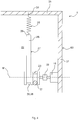
- the household appliance 1 comprises the housing 16, the door 3 pivotably connected to the housing 16, the spring element 25, the cable 17, which at its one end 18 with the door 3 and at its the other end 24 is connected to the spring element 25, and a linear drive 61, which is attached to the housing 16, is directly connected to the spring element 25 and is set up to move the spring element 25 in order to effect the pivoting movement of the door 3.
- One end 18 of the cable 17 is connected to the lever 21 and the other end 24 of the cable 17 is connected to the end 29 of the spring element 25.
- the other end 30 of the spring element 25 is in turn connected to the linear drive 61.
- the rope 17 is deflected with the aid of an element 62, which can be designed as a deflection roller or friction element.
- the spring element 25 can be displaced in translation. With the help of this translational displacement, the cable 17 is moved accordingly, so that the door 3 performs the pivoting movement.
- the motor 19, as in FIGS FIGS. 2 to 7 described be provided instead of the linear drive 61.
- the motor 19 with the cable drum 23 can be provided instead of the linear drive 61.
- Such a downstream motor 19 with respect to the spring element is set up, for example, to change a pretensioning of the spring element 25.
- the rope 17 and / or the further rope 42 and / or the auxiliary rope 27 can consist of several separate rope sections which are mechanically connected to one another. Furthermore, any number of friction elements or deflection rollers can be provided in order to deflect the cables 17, 27, 42 or to generate friction in a targeted manner. Furthermore, the ropes 17, 27, 42 can consist of any material. The ropes 17, 27, 42 can comprise metal, plastic, textile or some other material, for example.
Landscapes
- Engineering & Computer Science (AREA)
- Chemical & Material Sciences (AREA)
- Combustion & Propulsion (AREA)
- Mechanical Engineering (AREA)
- General Engineering & Computer Science (AREA)
- Power-Operated Mechanisms For Wings (AREA)
Abstract
Description
- Viele Haushaltsgeräte, wie beispielsweise Haushalts-Geschirrspülmaschinen, umfassen eine verschwenkbare Tür. Weiterhin kann das Haushaltsgerät eine Einrichtung umfassen, die die Gewichtskraft der Tür kompensieren kann, um ein Herunterfallen der Tür in geöffneter Stellung zu vermeiden. Dafür umfasst die Einrichtung beispielsweise ein Seil, welches mit seinem einen Ende mit der Tür und mit seinem anderen Ende mit einem Federelement verbunden ist. Das Federelement wiederum ist beispielsweise mit einem Gehäuse des Haushaltsgeräts verbunden. Bei einer Öffnungsbewegung der Tür wird beispielsweise die Feder vorgespannt, so dass eine Federkraft mit Hilfe des Seils derart an der Tür angreift, dass ein Herunterfallen der Tür vermieden wird. Weiterhin können Reibelemente vorgesehen sein, die eine Verschwenkbewegung der Tür erschweren. Eine entsprechende Reibkraft kann in geöffneter Stellung der Tür eine Differenz zwischen der Gewichtskraft der Tür, die an dem Seil zieht, und der Federkraft bilden.
- Die
EP 0 541 974 A1 zeigt beispielsweise eine Geschirrspülmaschine mit einem Gerätegehäuse, in welchem ein elektromotorischer Antrieb vorgesehen ist. Mit Hilfe des elektromotorischen Antriebs kann beispielsweise eine Gerätetür der Geschirrspülmaschine ganz oder teilweise geschlossen oder geöffnet werden. - Vor diesem Hintergrund besteht eine Aufgabe der vorliegenden Erfindung darin, ein verbessertes Haushaltsgerät zur Verfügung zu stellen.
- Demgemäß wird ein Haushaltsgerät bereitgestellt, mit einem Gehäuse, einer mit dem Gehäuse verschwenkbar verbundenen Tür, einem Seil, das an seinem einen Ende mit der Tür verbunden ist, einem Motor und einer Seiltrommel, auf die das Seil zumindest teilweise aufwickelbar und von der das Seil zumindest teilweise abwickelbar ist, wobei das Seil und der Motor dazu eingerichtet sind, eine Verschwenkbewegung der Tür mittels Aufwickelns des Seils auf die Seiltrommel oder mittels Abwickelns des Seils von der Seiltrommel zu bewirken.
- Indem eine Seiltrommel verwendet wird, kann eine besonders platzsparende Anordnung bereitgestellt werden. Beispielsweise kann mit Hilfe der Seiltrommel direkt auf die Verschwenkbewegung der Tür Einfluss genommen werden. Vorteilhafterweise kann dadurch ein robuster Türöffnungsmechanismus bereitgestellt werden, da beispielsweise eine direkte Kraftübertragung von der Seiltrommel auf das Seil, das an der Tür zieht, möglich ist. Außerdem kann ein Haushaltsgerät bereitgestellt werden, bei dem mit einer geringen Anzahl an Bauteilen eine automatische Türverschwenkbewegung realisiert werden kann.
- Das Haushaltsgerät ist vorzugsweise eine Haushalts-Geschirrspülmaschine, eine Waschmaschine, ein Kältegerät, vorzugsweise ein Kühlschrank, oder ein Backofen. Das Gehäuse ist vorzugsweise zumindest abschnittsweise ein äußerstes Gehäuse des Haushaltsgeräts. Vorzugsweise umfasst das Gehäuse ein Bodengehäuse und einen auf dem Bodengehäuse angeordneten Spülbehälter. Das Bodengehäuse umfasst beispielsweise einen Boden, zwei gegenüberliegende Außenwände und eine gegenüber der geschlossenen Tür angeordnete Rückwand. Vorzugsweise sind der Boden, die Außenwände und die Rückwand des Bodengehäuses miteinander verbunden und bilden eine im Wesentlichen quaderförmige Geometrie aus. Vorzugsweise ist die Tür mit Hilfe eines Scharniers mit dem Gehäuse verbunden. Beispielsweise wird die Tür zu einem Boden, auf dem das Haushaltsgerät steht, hin verschwenkt. Vorzugsweise umfasst die Tür einen Hebel, mit welchem das eine Ende des Seils verbunden ist. Beispielsweise ist ein anderes Ende des Seils mit der Seiltrommel verbunden. Der Motor ist beispielsweise ein Elektromotor. Beispielsweise sind der Motor, das Seil und die Seiltrommel redundant vorgesehen und entsprechend entlang der beiden Außenwände des Gehäuses angeordnet.
- "Seiltrommel" meint vorliegend beispielsweise eine drehbar gelagerte Rolle, die derart eingerichtet ist, dass das Seil auf die Rolle aufgewickelt oder von der Rolle abgewickelt werden kann. Dabei meint "Aufwickeln" ein Erhöhen einer Kontaktfläche zwischen dem Seil und der Seiltrommel und/oder, dass Seilabschnitte auf andere Abschnitte des Seils gelegt werden, so dass sich eine Spiralform ausbildet. Dabei meint "Abwickeln" ein Verringern der Kontaktfläche zwischen dem Seil und der Seiltrommel und/oder, dass Seilabschnitte von andere Abschnitte des Seils gelöst werden. Beispielsweise wird bei dem Abwickeln ein Umschlingungswinkel des Seils um die Seiltrommel verringert und bei dem Aufwickeln der Umschlingungswinkel des Seils um die Seiltrommel erhöht. Dabei kann der Umschlingungswinkel größer oder kleiner als 360° betragen. Beispielsweise wird mit Hilfe des Aufwickelns des Seils auf die Seiltrommel das eine Ende des Seils gezogen, so dass der Hebel der Tür geschwenkt wird und dadurch die Tür um das Scharnier rotiert. Vorzugsweise umfasst das Seil Kunststoff und/oder Metall. Alternativ oder zusätzlich kann das Seil Garn und/oder Textilien, insbesondere Naturfasern und/oder Chemiefasern, umfassen. Beispielsweise ist das Seil aus mehreren Seilabschnitten, die mechanisch miteinander verbunden sind, gebildet.
- Gemäß einer Ausführungsform ist die Seiltrommel mit dem Motor antriebsverbunden und/oder an den Motor angeflanscht.
- Dadurch kann die Seiltrommel direkt mit Hilfe des Motors angetrieben beziehungsweise rotiert werden. Weiterhin werden dadurch die Seiltrommel und der Motor platzsparend angeordnet. Beispielsweise umfasst der Motor eine Antriebswelle, auf der die Seiltrommel sitzt. Vorzugsweise ist der Motor fest mit dem Gehäuse verbunden. Beispielsweise können die Seiltrommel samt Motor auch als Seilwinde bezeichnet werden.
- Gemäß einer weiteren Ausführungsform umfasst das Haushaltsgerät ein weiteres Seil, das an seinem einen Ende mit der Tür verbunden ist, wobei das Seil und das weitere Seil synchron zumindest teilweise auf die Seiltrommel aufwickelbar und von der Seiltrommel zumindest teilweise abwickelbar sind, wobei das Seil, das weitere Seil und der Motor dazu eingerichtet sind, die Verschwenkbewegung der Tür mittels Aufwickelns des Seils und des weiteren Seils auf die Seiltrommel oder Abwickelns des Seils und des weiteren Seils von der Seiltrommel zu bewirken.
- Vorteilhaft ist, dass mit Hilfe der Seiltrommel, des Seils und des weiteren Seils zwei Kraftantriebspunkte an der Tür geschaffen werden können. Insbesondere kann dadurch beispielsweise eine sichere Verschwenkbewegung der Tür realisiert werden. Weiterhin kann ein Verkanten der Tür verhindert werden. Außerdem kann einer unsymmetrischen Verschwenkbewegung der Tür entgegengewirkt werden. Beispielsweise sind das eine Ende des weiteren Seils mit einem weiteren Hebel der Tür und das andere Ende des weiteren Seils mit der Seiltrommel verbunden. Vorzugsweise umfasst die Seiltrommel einen ersten Abschnitt, auf den das Seil aufwickelbar beziehungsweise von dem das Seil abwickelbar ist. Weiterhin umfasst die Seiltrommel beispielsweise einen zweiten Abschnitt, auf den das weitere Seil aufwickelbar beziehungsweise von dem das weitere Seil abwickelbar ist. Vorzugsweise sind der erste Abschnitt und der zweite Abschnitt der Seiltrommel koaxial angeordnet. Beispielsweise sind der erste Abschnitt und der zweite Abschnitt der Seiltrommel identisch ausgestaltet und fest miteinander verbunden. Weiterhin können der erste und zweite Abschnitt der Seiltrommel materialeinstückig ausgebildet sein.
- Gemäß einer weiteren Ausführungsform umfasst das Haushaltsgerät ein Federelement, das dazu eingerichtet ist, eine Gewichtskraft der Tür zumindest teilweise zu kompensieren.
- Dies hat den Vorteil, dass ein unkontrolliertes Auffallen der Tür vermieden werden kann. Weiterhin wird ein manuelles Verschließen der Tür erleichtert. Das Federelement ist vorzugsweise eine Schraubenfeder. Beispielsweise ist eine Federkennlinie des Federelements progressiv, degressiv oder linear. Beispielsweise wird das Federelement bei Vergrößerung eines Öffnungswinkels der Tür gelängt und dadurch vorgespannt. Vorzugsweise umfasst das Haushaltsgerät weiterhin ein Reibelement, das dazu eingerichtet ist, eine Reibkraft auf das Seil aufzubringen. Beispielsweise entspricht eine derartige Reibkraft einer Differenz zwischen der Gewichtskraft der Tür, die an dem Seil und gegebenenfalls an dem weiteren Seil zieht, und der Federkraft. Beispielsweise kann mit Hilfe des Reibelements die Tür eine ruhende Position bei einem beliebigen Öffnungswinkel annehmen. Da die Gewichtskraft der Tür mit Hilfe des Federelements zumindest teilweise kompensiert wird, kann ein Motor mit geringer Motorleistung verwendet werden.
- Gemäß einer weiteren Ausführungsform umfasst das Haushaltsgerät ein Rotationselement, das dazu eingerichtet ist, das Federelement zu spannen.
- Vorteilhaft ist, dass das Federelement mit Hilfe einer rotatorischen Bewegung gespannt beziehungsweise entspannt werden kann und dadurch eine platzsparende Anordnung geschaffen wird. Beispielsweise ist das Federelement mit seinem einen Ende direkt mit dem Rotationselement verbunden. Beispielsweise ist das Federelement mit seinem anderen Ende mit dem Gehäuse verbunden. Beispielsweise sind das Rotationselement und die Seiltrommel miteinander antriebsverbunden.
- Gemäß einer weiteren Ausführungsform umfasst das Haushaltsgerät ein Hilfsseil, wobei das Rotationselement als Hilfsseiltrommel ausgebildet ist, wobei das Hilfsseil auf die Hilfsseiltrommel zumindest teilweise aufwickelbar und von der Hilfsseiltrommel zumindest teilweise abwickelbar ist und an seinem einen Ende mit dem Federelement verbunden ist.
- Vorteilhafterweise kann mit Hilfe des Hilfsseils eine indirekte Verbindung (Seilverbindung) zwischen dem Rotationselement und dem Federelement gebildet werden. Vorzugsweise ist die Hilfsseiltrommel koaxial zu der Seiltrommel angeordnet. Beispielsweise ist die Hilfsseiltrommel fest mit der Seiltrommel verbunden. Dabei können die Hilfsseiltrommel und die Seiltrommel als eine einzige Seiltrommel ausgebildet sein. Beispielsweise sind die Seiltrommel und die Hilfsseiltrommel dazu eingerichtet, das Seil aufzuwickeln und zeitgleich das Hilfsseil abzuwickeln beziehungsweise das Seil abzuwickeln und zeitgleich das Hilfsseil aufzuwickeln. Dabei werden beispielsweise das Hilfsseil und das Seil parallel zueinander aufgewickelt beziehungsweise abgewickelt. Weiterhin hat das Verwenden der Seiltrommel und der Hilfsseiltrommel den Vorteil, dass vorzugsweise kein Schlupf zwischen dem Seil und der Seiltrommel und/oder dem Hilfsseil und der Hilfsseiltrommel auftritt.
- Gemäß einer weiteren Ausführungsform ist das Rotationselement als Hebel ausgebildet, der mit der Seiltrommel antriebsverbunden und mit dem Federelement verbunden ist.
- Das Verwenden eines Hebels hat beispielsweise den Vorteil, dass das Federelement direkt mit dem Hebel verbunden werden kann und beispielsweise dadurch auf ein Hilfsseil verzichtet werden kann. Beispielsweise sind der Hebel und die Seiltrommel als integrales Spritzgussbauteil gefertigt. Beispielsweise sind die Seiltrommel und der Hebel dazu eingerichtet, um die gleiche Mittelachse zu rotieren.
- Gemäß einer weiteren Ausführungsform ist ein erstes Ende des Federelements mit einem anderen Ende des Seils verbunden und ein zweites Ende des Federelements mit dem Motor und/oder der Seiltrommel verbunden.
- Damit ist das Federelement beispielsweise zwischen dem Seil und dem Motor und/oder der Seiltrommel angeordnet.
- Gemäß einer weiteren Ausführungsform umfasst das Haushaltsgerät eine Kupplung, die dazu eingerichtet ist, eine Antriebsverbindung zwischen dem Motor und der Seiltrommel und/oder dem Seil zu trennen.
- Vorteilhafterweise kann mit Hilfe der Kupplung der Motor von der Verschwenkbewegung der Tür entkoppelt werden. Beispielsweise kann eine derartige Entkopplung als Leerlaufschaltung bezeichnet werden. Beispielsweise kann dadurch der Motor geschont werden und/oder ein Widerstand für eine manuelle Bewegung der Tür verringert werden. Vorzugsweise ist die Kupplung dazu eingerichtet, bei Überschreiten eines Türgrenzwiderstands auszulösen, so dass die Antriebsverbindung zwischen dem Motor und der Seiltrommel und/oder dem Seil getrennt wird. Beispielsweise wird ein derartiger Türgrenzwiderstand bei Einklemmen eines Gegenstands zwischen dem Gehäuse und der Tür erreicht. Vorteilhafterweise kann dadurch eine Sicherheitseinrichtung geschaffen werden, durch die Quetschungen vermieden werden können. Eine Verletzungsgefahr an Scher- und Klemmstellen ist damit reduziert. Beispielsweise ist die Kupplung als Rutschkupplung oder Trennkupplung ausgebildet.
- Gemäß einer weiteren Ausführungsform umfasst das Haushaltsgerät eine Steuereinrichtung, die dazu eingerichtet ist, den Motor derart anzusteuern, dass eine Verschwenkbewegung der Tür bewirkt wird.
- Vorteilhafterweise kann dadurch beispielsweise eine vollautomatische Verschwenkbewegung der Tür realisiert werden. Beispielsweise sind die Steuereinrichtung und der Motor signaltechnisch miteinander gekoppelt. Vorzugsweise ist die Steuereinrichtung dazu eingerichtet, eine vollständige Öffnungsbewegung der Tür anzusteuern. Weiterhin kann die Steuereinrichtung beispielweise dazu eingerichtet sein, eine vollständige Verschließbewegung der Tür anzusteuern. Beispielsweise ist die Steuereinrichtung signaltechnisch mit der Kupplung verbunden. Dabei kann die Steuereinrichtung dazu eingerichtet sein, die Kupplung, insbesondere die Trennkupplung, zu betätigen. Beispielsweise ist die Steuereinrichtung dazu eingerichtet, den Motor zum Öffnen der Tür anzusteuern, um einer Geruchsbildung innerhalb des Haushaltsgeräts entgegenzuwirken.
- Gemäß einer weiteren Ausführungsform ist die Steuereinrichtung dazu eingerichtet, den Motor in einen Generatorbetrieb zu schalten, um einen Widerstand entgegen der Verschwenkbewegung der Tür zu erzeugen.
- Vorteilhafterweise kann dadurch ein haptisches Feedback an der Tür optimiert werden. Beispielsweise kann mit Hilfe des Widerstands die Differenz zwischen der Gewichtskraft der Tür, die am Seil zieht, und der Federkraft kompensiert werden.
- Gemäß einer weiteren Ausführungsform umfasst das Haushaltsgerät eine Bedienerschnittstelle, die dazu eingerichtet ist, mit der Steuereinrichtung zu kommunizieren.
- Dies hat den Vorteil, dass unterschiedliche Öffnungs- oder Schließfunktionen der Tür in das Haushaltsgerät implementiert werden können. Beispielsweise umfasst die Bedienerschnittstelle einen Druckknopf, ein Touch-Display, ein Mikrofon oder eine sonstige Eingabevorrichtung beziehungsweise Ausgabevorrichtung. Weiterhin kann die Bedienerschnittstelle einen Sensor umfassen, der dazu eingerichtet ist, eine Bedienereingabe, insbesondere eine Geste des Bedieners, zu erfassen.
- Gemäß einer weiteren Ausführungsform umfasst das Haushaltsgerät eine Ausgabevorrichtung, die dazu eingerichtet ist, während der Verschwenkbewegung der Tür ein akustisches Signal und/oder optisches Signal auszugeben.
- Dies hat den Vorteil, dass Personen, die sich in der Nähe des Haushaltsgeräts befinden, mit Hilfe des akustischen Signals und/oder optischen Signals gewarnt werden. Hierdurch können beispielsweise ungewollte Kollisionen zwischen der Tür und den Personen vermieden werden. Vorzugsweise umfasst die Ausgabevorrichtung einen Lautsprecher zum Ausgeben des akustischen Signals und/oder eine Lichtquelle zum Ausgeben des optischen Signals.
- Gemäß einer weiteren Ausführungsform umfasst das Haushaltsgerät eine Feststellbremse, die dazu eingerichtet ist, eine Aufwickelbewegung und/oder Abwickelbewegung der Seiltrommel und/oder die Verschwenkbewegung der Tür zu unterbinden.
- Beispielsweise ist die Feststellbremse dazu eingerichtet, eine Auffallbewegung der Tür zu unterbinden. Vorzugsweise ist die Feststellbremse signaltechnisch mit der Steuereinrichtung verbunden.
- Weiterhin wird ein Haushaltsgerät vorgeschlagen, mit einem Gehäuse, einer mit dem Gehäuse verschwenkbar verbundenen Tür, einem Federelement, einem Seil, das an seinem einen Ende mit der Tür und an seinem anderen Ende mit dem Federelement verbunden ist, und einem Linearantrieb, der an dem Gehäuse befestigt ist, unmittelbar mit dem Federelement verbunden ist und dazu eingerichtet ist, das Federelement zu bewegen, um eine Verschwenkbewegung der Tür zu bewirken.
- Mit Hilfe des Linearantriebs, der unmittelbar mit dem Federelement verbunden ist, kann ein kompakter Türöffnungsmechanismus bereitgestellt werden. Weiterhin kann ein einfacher und eindeutiger Wirkmechanismus bereitgestellt werden. Vorzugsweise umfasst der Linearantrieb einen Spindelantrieb oder ist der Linearantrieb als Spindelantrieb ausgebildet. Die für das Haushaltsgerät mit der Seiltrommel genannten Vorteile und Ausführungsformen gelten entsprechend für das den Linearantrieb umfassende Haushaltsgerät.
- Weitere mögliche Implementierungen der Erfindung umfassen auch nicht explizit genannte Kombinationen von zuvor oder im Folgenden bezüglich der Ausführungsbeispiele beschriebenen Merkmale oder Ausführungsformen. Dabei wird der Fachmann auch Einzelaspekte als Verbesserungen oder Ergänzungen zu der jeweiligen Grundform der Erfindung hinzufügen.
- Weitere vorteilhafte Ausgestaltungen und Aspekte der Erfindung sind Gegenstand der Unteransprüche sowie der im Folgenden beschriebenen Ausführungsbeispiele der Erfindung. Im Weiteren wird die Erfindung anhand von bevorzugten Ausführungsformen unter Bezugnahme auf die beigelegten Figuren näher erläutert.
-
Fig. 1 zeigt eine schematische perspektivische Ansicht einer Ausführungsform eines Haushaltsgeräts; -
Fig. 2 zeigt eine schematische Seitenansicht einer weiteren Ausführungsform eines Haushaltsgeräts; -
Fig. 3 zeigt eine schematische Seitenansicht einer weiteren Ausführungsform eines Haushaltsgeräts; -
Fig. 4 zeigt einen schematischen Teilschnitt IV - IV ausFig.1 ; -
Fig. 5 zeigt eine schematische Aufsicht einer weiteren Ausführungsform eines Haushaltsgeräts; -
Fig. 6 zeigt eine schematische Aufsicht einer weiteren Ausführungsform eines Haushaltsgeräts; -
Fig. 7 zeigt eine schematische Aufsicht einer weiteren Ausführungsform eines Haushaltsgeräts; und -
Fig. 8 zeigt eine schematische Seitenansicht einer weiteren Ausführungsform eines Haushaltsgeräts. - In den Figuren sind gleiche oder funktionsgleiche Elemente mit denselben Bezugszeichen versehen worden, sofern nichts anderes angegeben ist.
-
Fig. 1 zeigt eine schematische perspektivische Ansicht eines Haushaltsgeräts 1. Das Haushaltsgerät 1 ist beispielsweise eine Haushalts-Geschirrspülmaschine. Alternativ kann das Haushaltsgerät 1 als Waschmaschine, Kältegerät, zum Beispiel als Kühlschrank, oder als Backofen ausgebildet sein. Das Haushaltsgerät 1 umfasst einen Spülbehälter 2, der durch eine Tür 3, insbesondere wasserdicht, verschließbar ist. Hierzu kann zwischen der Tür 3 und dem Spülbehälter 2 eine Dichteinrichtung vorgesehen sein. Der Spülbehälter 2 ist vorzugsweise quaderförmig. Der Spülbehälter 2 ist in einem Gehäuse 16 (nur teilweise dargestellt) des Haushaltsgeräts 1 angeordnet. Der Spülbehälter 2 und die Tür 3 können einen Spülraum 4 zum Spülen von Spülgut bilden. - Die Tür 3 ist in der
Fig. 1 in ihrer geöffneten Stellung dargestellt. Durch ein Verschwenken um eine an einem unteren Ende der Tür 3 vorgesehene Schwenkachse 5 kann die Tür 3 geschlossen oder geöffnet werden. Mit Hilfe der Tür 3 kann eine Beschickungsöffnung 6 des Spülbehälters 2 geschlossen oder geöffnet werden. Der Spülbehälter 2 weist ein Bodenblech 7, eine dem Bodenblech 7 gegenüberliegend angeordnete Decke 8, eine der geschlossenen Tür 3 gegenüberliegend angeordnete Rückwand 9 und zwei einander gegenüberliegend angeordnete Seitenwände 10, 11 auf. Das Bodenblech 7, die Decke 8, die Rückwand 9 und die Seitenwände 10, 11 können beispielsweise aus einem Stahlblech gefertigt sein. Insbesondere kann beispielsweise das Bodenblech 7 aus einem anderen Material gefertigt sein als die Decke 8 und die Seitenwände 10, 11. Beispielsweise kann das Bodenblech 7 aus dem Werkstoff 1.4301, die Decke 8 und die Seitenwände 10, 11 aus dem Werkstoff 1.4016 und die Rückwand 9 ebenfalls aus dem Werkstoff 1.4916 gefertigt sein. - Eine erste Seitenwand 10, eine zweite Seitenwand 11 und die zwischen der ersten Seitenwand 10 und der zweiten Seitenwand 11 angeordnete Decke 8 sind einteilig, insbesondere materialeinstückig, ausgebildet und bilden einen Spülbehältermantel 12 des Spülbehälters 2. Der Spülbehältermantel 12, die Rückwand 9 und das Bodenblech 7 sind voneinander getrennt gefertigte Bauteile, die jedoch wasserdicht miteinander verbunden sind. Der Spülbehälter 2 ist auf einem Bodengehäuse 63 angeordnet und mit diesem verbunden. Das Haushaltsgerät 1 umfasst ein Gehäuse 16, welches das Bodengehäuse 63 und den Spülbehälter 2 umfasst. Das Bodengehäuse 63 umfasst einen Boden 50, zwei Außenwände 37, 41 (siehe
Fig. 5 ) und eine gegenüber der geschlossenen Tür 3 angeordnete Rückwand 36 (sieheFig. 5 ). - Das Haushaltsgerät 1 weist ferner zumindest eine Spülgutaufnahme 13 bis 15 auf. Vorzugsweise können mehrere, beispielsweise drei, Spülgutaufnahmen 13 bis 15 vorgesehen sein, wobei die Spülgutaufnahme 13 eine untere Spülgutaufnahme oder ein Unterkorb, die Spülgutaufnahme 14 eine obere Spülgutaufnahme oder ein Oberkorb und die Spülgutaufnahme 15 eine Besteckschublade sein kann. Wie die
Fig. 1 weiterhin zeigt, sind die Spülgutaufnahmen 13 bis 15 übereinander in dem Spülbehälter 2 angeordnet. Jede Spülgutaufnahme 13 bis 15 ist wahlweise in den Spülbehälter 2 hinein- oder aus diesem herausverlagerbar. Insbesondere ist jede Spülgutaufnahme 13 bis 15 in einer Einschubrichtung E in den Spülbehälter 2 hineinschiebbar und entgegen der Einschubrichtung E in einer Auszugsrichtung A aus dem Spülbehälter 2 herausziehbar. - Anstelle des Spülbehälters 2 kann auch ein Waschbehälter, ein Kühlbehälter oder ein Garbehälter vorgesehen sein.
-
Fig. 2 zeigt eine schematische Seitenansicht einer weiteren Ausführungsform des Haushaltsgeräts 1. Das Haushaltsgerät 1 umfasst das Gehäuse 16 und die Tür 3, die mit Hilfe eines Scharniers 20 mit dem Gehäuse 16 verschwenkbar verbunden ist. Weiterhin umfasst die Tür 3 einen Hebel 21, der in einen Innenraum 22 des Gehäuses 16 hineinragt. Mittels Bewegen des Hebels 21 kann die gesamte Tür 3 um die Schwenkachse 5, die durch das Scharnier 20 verläuft, geöffnet und geschlossen werden. Weiterhin umfasst das Haushaltsgerät 1 ein Seil 17, das an seinem einen Ende 18 mit dem Hebel 21 verbunden ist. Außerdem umfasst das Haushaltsgerät 1 einen Motor 19, der mit dem Gehäuse 16 oder dem Spülbehälter 3 (sieheFig. 1 ) verbunden ist, und eine Seiltrommel 23, auf die das Seil 17 zumindest teilweise aufwickelbar und von der das Seil 17 zumindest teilweise abwickelbar ist. Das Seil 17 und der Motor 19 sind dazu eingerichtet, eine Verschwenkbewegung der Tür 3 mittels Aufwickelns des Seils 17 auf die Seiltrommel 23 oder mittels Abwickelns des Seils 17 von der Seiltrommel 23 zu bewirken. Beispielsweise ist die Seiltrommel 23 mit dem Motor 19 antriebsverbunden. Der Motor 19 ist dazu eingerichtet, eine Drehbewegung der Seiltrommel 23 zu bewirken. Beispielsweise ist ein zweites Ende 24 des Seils 17 fest mit der Seiltrommel 23 verbunden. -
Fig. 3 zeigt eine schematische Seitenansicht einer weiteren Ausführungsform des Haushalsgeräts 1. Im Unterschied zurFig. 2 umfasst das Haushaltsgerät 1 ein Federelement 25, das dazu eingerichtet ist, eine Gewichtskraft G der Tür 3 zumindest teilweise zu kompensieren. Weiterhin umfasst das Haushaltsgerät 1 ein Rotationselement 26, das dazu eingerichtet ist, das Federelement 25 zu spannen (Rotationselement 26 inFig. 3 nicht sichtbar). Beispielsweise ist das Rotationselement 26 starr mit der Seiltrommel 23 verbunden. Bei einer Drehung der Seiltrommel 23 würde sich somit das Rotationselement 26 mitdrehen. - Ferner umfasst das Haushaltsgerät 1 ein Hilfsseil 27, das mit dem Rotationselement 26 verbunden ist. Dabei ist das Hilfsseil 27 mit seinem einen Ende 28 mit einem Ende 29 des Federelements 25 verbunden. Weiterhin ist das andere Ende 30 des Federelements 25 an dem Gehäuse 16 angebunden. Damit lässt sich das Federelement 25 mit Hilfe des Hilfsseils 27 spannen. Dabei wird das Hilfsseil 27 mit Hilfe des Rotationselementes 26 freigegeben oder gezogen. Beim Ziehen des Hilfsseils 27 wird das Federelement 25 gelängt und damit vorgespannt. Beim Freigeben des Hilfsseils 27 zieht sich das Federelement 25 wieder zusammen. Das Haushaltsgerät 1 umfasst ferner ein Reibelement 31, an dem das Seil 17 reibt. Dabei wird eine Reibkraft erzeugt, um eine ungewollte Verschwenkbewegung der Tür 3 zu hemmen. Dies ist insbesondere dann hilfreich, wenn eine Zugkraft in dem Seil 17 aufgrund der Gewichtskraft G der Tür 3 eine Federkraft übersteigt oder die Federkraft die Zugkraft in dem Seil 17 aufgrund der Gewichtskraft G übersteigt. Für den Fall, dass sich das Gesamtsystem im Kräftegleichgewicht befindet, reicht beispielsweise ein einseitiger Kraftangriff an dem Hebel 21 aus um die gesamte Tür 3 aus der Ruhelage zu bringen. Anstelle des Reibelements 31 kann auch eine Umlenkrolle vorgesehen sein.
- Das Haushaltsgerät 1 umfasst weiterhin eine Steuereinrichtung 32, die dazu eingerichtet ist, den Motor 19 derart anzusteuern, dass die Tür 3 die Verschwenkbewegung ausführt. Die Steuereinrichtung 32 ist mit dem Motor 19 signaltechnisch gekoppelt (gestrichelt angedeutet). Beispielsweise ist die Steuereinrichtung 32 dazu eingerichtet, den Motor 19 in einen Generatorbetrieb zu schalten, um einen Widerstand entgegen der Verschwenkbewegung der Tür 3 zu erzeugen. Hierdurch kann beispielsweise ein haptisches Feedback für einen Bediener, der die Verschwenkbewegung der Tür 3 manuell ausführt, verbessert werden. Beispielsweise umfasst das Haushaltsgerät 1 eine Bedienerschnittstelle 33, die dazu eingerichtet ist, mit der Steuereinrichtung 32 zu kommunizieren. Die Bedienerschnittstelle 33 kann beispielsweise einen Druckknopf, Touch-Display, Mikrofon, einen Sensor oder eine sonstige Eingabevorrichtung oder Ausgabevorrichtung umfassen. Die Bedienerschnittstelle 33 ist mit der Steuereinrichtung 32 signaltechnisch gekoppelt (gestrichelt angedeutet). Weiterhin kann das Haushaltsgerät 1 einen Sensor 34 umfassen, der beispielsweise in der Tür 3 oder in dem Scharnier 20 angeordnet und dazu eingerichtet ist, die Verschwenkbewegung der Tür 3 zu erfassen. Auch der Sensor 34 ist signaltechnisch mit der Steuereinrichtung 32 verbunden (gestrichelt angedeutet). Beispielsweise kann mit Hilfe der Bedienerschnittstelle 33 und/oder des Sensors 34 ein automatisches Schließen der Tür 3 mit Hilfe einer Fußberührung durch den Bediener oder mit Hilfe einer Erfassung einer Fußstellung oder Fußgeste des Bedieners realisiert werden. Weiterhin ist es denkbar, ein vollständiges Schließen oder vollständiges Öffnen der Tür 3 mit Hilfe einer App-Steuerung einzuleiten. Beispielsweise öffnet sich die geschlossene Tür 3 mit Hilfe eines Druckeintrags durch den Bediener des Haushaltsgeräts 1. Beispielsweise wird die Tür 3 in einer beliebigen Stellung nach unten oder nach oben gedrückt und setzt die Türbewegung dann automatisch fort. Außerdem kann beispielsweise vorgesehen sein, dass mit Hilfe einer Betätigung der Bedienerschnittstelle 33, insbesondere einer Tastenbetätigung, das Öffnen der Tür 3 eingeleitet wird.
- Ferner kann das Haushaltsgerät 1 eine Ausgabevorrichtung 35 umfassen, die dazu eingerichtet ist, während der Verschwenkbewegung der Tür 3 ein akustisches Signal auszugeben. Die Ausgabevorrichtung 35 umfasst beispielsweise einen Lautsprecher. Beispielsweise ist die Ausgabevorrichtung 35 mit der Steuereinrichtung 32 signaltechnisch gekoppelt (gestrichelt angedeutet).
- Das Seil 17 und/oder der Hebel 21 und/oder die Seiltrommel 23 und/oder der Motor 19 und/oder das Rotationselement 26 und/oder das Hilfsseil 27 und/oder das Federelement 25 kann beispielsweise wie vorstehend oder nachstehend beschrieben ausgeführt sein und redundant, insbesondere entlang der Seitenwand 10 (siehe
Fig. 1 ) und entlang der Seitenwand 11 (sieheFig. 1 ), vorgesehen sein. -
Fig. 4 zeigt einen Teilschnitt IV - IV ausFig. 1 , der horizontal durch das Haushaltsgerät 1 verläuft. Das Bodengehäuse 63 umfasst dabei die Außenwand 37.Weiterhin ist das Rotationselement 26 als Hilfsseiltrommel 38 ausgebildet. Die Hilfsseiltrommel 38 ist fest mit der Seiltrommel 23 verbunden. Dabei können beispielsweise die Hilfsseiltrommel 38 und die Seiltrommel 23 identisch ausgestaltet sein. Beispielsweise können die Seiltrommel 23 und die Hilfsseiltrommel 38 als Doppelseiltrommel ausgebildet sein. Insbesondere sind die Seiltrommel 23 und die Hilfsseiltrommel 38 aus Metall oder Kunststoff gefertigt. Beispielsweise sind die Seiltrommel 23 und die Hilfsseiltrommel 38 koaxial angeordnet und um eine Mittelachse M drehbar. Insbesondere kann bezüglich der Mittelachse M eine Rotationssymmetrie der Seiltrommel 23 und der Hilfsseiltrommel 38 vorliegen. Beispielsweise ist das Hilfsseil 27 auf die Hilfsseiltrommel 38 zumindest teilweise aufwickelbar und von der Hilfsseiltrommel 38 zumindest teilweise abwickelbar und an seinem einen Ende 28 mit dem Federelement 25 verbunden. - Der Motor 19 ist beispielsweise mit der Außenwand 37 verbunden und koaxial zu der Seiltrommel 23 und zu der Hilfsseiltrommel 38 angeordnet. Beispielsweise sind die Seiltrommel 23 und die Hilfsseiltrommel 38 an dem Motor 19 gelagert, wobei eine Kupplung 39 zwischen der Seiltrommel 23 und dem Motor 19 angeordnet ist. Beispielsweise ist die Kupplung 39 dazu eingerichtet, eine Antriebsverbindung zwischen dem Motor 19 und der Seiltrommel 23 und/oder dem Seil 17 zu trennen. Die Kupplung 39 ist beispielsweise eine Rutschkupplung. Beispielsweise kann die Seiltrommel 23 an den Motor 19 angeflanscht sein.
-
Fig. 5 zeigt in einer schematischen Aufsicht eine weitere Ausführungsform des Haushaltsgeräts 1. Dabei umfasst das Haushaltsgerät 1 ein weiteres Seil 42, das an seinem einen Ende 44 mit einem weiteren Hebel 43 der Tür 3 verbunden ist, wobei das Seil 17 und das weitere Seil 42 synchron zumindest teilweise auf die Seiltrommel 23 aufwickelbar und von der Seiltrommel 23 zumindest teilweise abwickelbar sind. Das Seil 17, das weitere Seil 42 und der Motor 19 sind dazu eingerichtet, die Verschwenkbewegung der Tür 3 mittels Aufwickelns des Seils 17 und des weiteren Seils 42 auf die Seiltrommel 23 oder Abwickelns des Seils 17 und des weiteren Seils 42 von der Seiltrommel 23 zu bewirken. Die Seiltrommel 23 umfasst dabei einen ersten Abschnitt 45, von dem das Seil 17 abwickelbar ist. Weiterhin umfasst die Seiltrommel 23 einen zweiten Abschnitt 46, von dem das weitere Seil 42 abwickelbar ist. Der erste Abschnitt 45 und der zweite Abschnitt 46 sind nebeneinander und koaxial zu der Mittelachse M angeordnet. Beispielsweise ist der zweite Abschnitt 46 materialeinstückig an den ersten Abschnitt 45 angeformt. Der erste Abschnitt 45 und der zweite Abschnitt 46 können beispielsweise identisch ausgestaltet sein. - Das Seil 17 verläuft von dem ersten Abschnitt 45 hin zu der Außenwand 37, verläuft um eine Umlenkrolle 47 und verläuft im Anschluss entlang der Außenwand 37 hin zu der Tür 3. Vorzugsweise wird das Seil 17 mittels der Umlenkrolle 47 um 90° umgelenkt. Das weitere Seil 42 verläuft von dem zweiten Abschnitt 46 hin zu der Außenwand 41, verläuft um eine Umlenkrolle 48 und verläuft im Anschluss entlang der Außenwand 41 hin zu der Tür 3. Vorzugsweise erfolgt die Umlenkung mit Hilfe der Umlenkrolle 48 um 90°. Vorteilhaft ist, dass mit Hilfe eines einzigen Motors 19 zwei Seile 17, 42 abgewickelt und aufgewickelt werden, die jeweils an der Tür 3 befestigt sind. Außerdem wird mit Hilfe des Motors 19 auch die Hilfsseiltrommel 38 angetrieben, mit Hilfe welcher das Federelement 25 gespannt und entspannt werden kann, um die Gewichtskraft G der Tür 3 zu kompensieren.
- Ferner umfasst das Haushaltsgerät 1 eine Feststellbremse 49, die dazu eingerichtet ist, eine Aufwickelbewegung und/oder eine Abwickelbewegung der Seiltrommel 23 und/oder die Verschwenkbewegung der Tür 3 zu unterbinden. Beispielsweise ist die Feststellbremse 49 zwischen dem Motor 19 und der Seiltrommel 23 angeordnet. Alternativ kann die Feststellbremse 49 auch im Motor 19 vorgesehen sein. Beispielsweise kann mit Hilfe der Feststellbremse 39 ein bestimmter Öffnungswinkel der Tür 3 fixiert werden.
- Der Motor 19, die Seiltrommel 23 und die Hilfsseiltrommel 38 können zentral in dem Haushaltsgerät 1 vorgesehen sein. Damit verläuft die Mittelachse M durch eine Vertikalebene K, die das Haushaltsgerät 1 in zwei gleich große Hälften teilt. Weiterhin verläuft das Hilfsseil 27 von der Hilfsseiltrommel 38 hin zu der Außenwand 37, wobei das Hilfsseil 27 mit Hilfe des Federelements 25 mit der Außenwand 37 verbunden ist. Alternativ kann das Hilfsseil zur Außenwand 41 verlaufen und mit der Außenwand 41 mit Hilfe des Federelements 25 verbunden sein. Außerdem verläuft die Mittelachse M von der geschlossenen Tür 3 hin zu der Rückwand 36. Der Motor 19 und/oder die Seiltrommel 23 und/oder die Hilfsseiltrommel 38 und/oder das Seil 17 und/oder das weitere Seil 42 und/oder das Hilfsseil 27 und/oder das Federelement 25 können beispielsweise zwischen dem Boden 50 des Bodengehäuses 63 und dem Bodenblech 7 (siehe
Fig. 1 ) des Spülbehältermantels 12 angeordnet sein. -
Fig. 6 zeigt in einer schematischen Aufsicht betrachtet eine weitere Ausführungsform des Haushaltsgeräts 1. Im Unterschied zurFig. 5 verläuft die Mittelachse M senkrecht nach oben von dem Boden 50 hin zu der Decke 8 (sieheFig. 1 ). Damit weisen zumindest der Motor 19 und die Seiltrommel 23 eine andere Orientierung auf als inFig. 5 gezeigt. Außerdem ist das Rotationselement 26 als Hebel 51 ausgebildet. Der Hebel 51 ist starr mit der Seiltrommel 23 gekoppelt und rotiert um die Mittelachse M, wenn das Seil 17 aufgewickelt und/oder abgewickelt wird. Dabei ist der Hebel 51 mit seinem einen Ende 52 mit der Seiltrommel 23 verbunden und mit seinem anderen Ende 53 an dem einen Ende 29 des Federelements 25 befestigt. Somit ist der Hebel 51 mit der Seiltrommel 23 antriebsverbunden und mit dem Federelement 25 verbunden. Mit Hilfe des Motors 19 wird eine Schwenkbewegung des Hebels 51 bewirkt und damit das Federelement 25 gespannt und/oder entspannt. -
Fig. 7 zeigt in einer schematischen Aufsicht eine weitere Ausführungsform des Haushaltsgeräts 1. Im Unterschied zurFig. 6 ist kein Rotationselement 26 vorgesehen. Weiterhin weist das Seil 17 einen unterbrochenen Bereich 54 auf, in welchem das Federelement 25 angeordnet ist. Mit anderen Worten ist das Seil 17 in einen ersten Seilabschnitt 55 und einen zweiten Seilabschnitt 56 aufgeteilt, die mit Hilfe des Federelements 25 verbunden sind. Das Federelement 25 ist mit Hilfe des zweiten Seilabschnitts 56 mit der Tür 3 verbunden. In Analogie dazu weist das weitere Seil 42 einen unterbrochenen Bereich 57 auf, in dem ein weiteres Federelement 58 angeordnet ist. Mit anderen Worten ist das weitere Seil 42 in einen ersten Seilabschnitt 59 und einen zweiten Seilabschnitt 60 aufgeteilt, die mit Hilfe des weiteren Federelements 58 miteinander verbunden sind. Das weitere Federelement 58 ist mit Hilfe des zweiten Seilabschnitts 60 mit der Tür 3 verbunden. -
Fig. 8 zeigt eine schematische Seitenansicht einer weiteren Ausführungsform des Haushaltsgeräts 1. Das Haushaltsgerät 1 umfasst das Gehäuse 16, die mit dem Gehäuse 16 verschwenkbar verbundene Tür 3, das Federelement 25, das Seil 17, welches an seinem einen Ende 18 mit der Tür 3 und an seinem anderen Ende 24 mit dem Federelement 25 verbunden ist, und einen Linearantrieb 61, der an dem Gehäuse 16 befestigt ist, unmittelbar mit dem Federelement 25 verbunden ist und dazu eingerichtet ist, das Federelement 25 zu bewegen, um die Verschwenkbewegung der Tür 3 zu bewirken. - Dabei ist das eine Ende 18 des Seils 17 mit dem Hebel 21 und das andere Ende 24 des Seils 17 mit dem Ende 29 des Federelements 25 verbunden. Das andere Ende 30 des Federelements 25 ist wiederum mit dem Linearantrieb 61 verbunden. Weiterhin wird das Seil 17 mit Hilfe eines Elements 62, das als Umlenkrolle oder Reibelement ausgebildet sein kann, umgelenkt. Mit Hilfe des Linearantriebs 61 kann das Federelement 25 translatorisch verschoben werden. Mit Hilfe dieser translatorischen Verschiebung wird entsprechend das Seil 17 bewegt, so dass die Tür 3 die Verschwenkbewegung vollzieht. Beispielsweise kann anstelle des Linearantriebs 61 der Motor 19, wie in den
Fig. 2 bis Fig. 7 beschrieben, vorgesehen sein. Weiterhin kann der Motor 19 mit der Seiltrommel 23 anstelle des Linearantriebs 61 vorgesehen sein. Ein derartig bezüglich des Federelements nachgeschalteter Motor 19 ist beispielsweise dazu eingerichtet, eine Vorspannung des Federelements 25 zu verändern. - Das Seil 17 und/oder das weitere Seil 42 und/oder das Hilfsseil 27 kann aus mehreren voneinander getrennten Seilabschnitten bestehen, die mechanisch miteinander verbunden sind. Weiterhin kann eine beliebige Anzahl an Reibelementen oder Umlenkrollen vorgesehen sein, um die Seile 17, 27, 42 umzulenken oder gezielt Reibung zu erzeugen. Weiterhin können die Seile 17, 27, 42 aus einem beliebigen Material bestehen. Die Seile 17, 27, 42 können beispielsweise Metall, Kunststoff, Textil oder ein sonstiges Material umfassen.
- Obwohl die vorliegende Erfindung anhand von Ausführungsbeispielen beschrieben wurde, ist sie vielfältig modifizierbar.
-
- 1
- Haushaltsgerät
- 2
- Spülbehälter
- 3
- Tür
- 4
- Spülraum
- 5
- Schwenkachse
- 6
- Beschickungsöffnung
- 7
- Bodenblech
- 8
- Decke
- 9
- Rückwand
- 10
- Seitenwand
- 11
- Seitenwand
- 12
- Spülbehältermantel
- 13
- Spülgutaufnahme
- 14
- Spülgutaufnahme
- 15
- Spülgutaufnahme
- 16
- Gehäuse
- 17
- Seil
- 18
- Ende
- 19
- Motor
- 20
- Scharnier
- 21
- Hebel
- 22
- Innenraum
- 23
- Seiltrommel
- 24
- Ende
- 25
- Federelement
- 26
- Rotationselement
- 27
- Hilfsseil
- 28
- Ende
- 29
- Ende
- 30
- Ende
- 31
- Reibelement
- 32
- Steuereinrichtung
- 33
- Bedienerschnittstelle
- 34
- Sensor
- 35
- Ausgabevorrichtung
- 36
- Rückwand
- 37
- Außenwand
- 38
- Hilfsseiltrommel
- 39
- Kupplung
- 41
- Außenwand
- 42
- Seil
- 43
- weiterer Hebel
- 44
- Ende
- 45
- Abschnitt
- 46
- Abschnitt
- 47
- Umlenkrolle
- 48
- Umlenkrolle
- 49
- Feststellbremse
- 50
- Boden
- 51
- Hebel
- 52
- Ende
- 53
- Ende
- 54
- Bereich
- 55
- Seilabschnitt
- 56
- Seilabschnitt
- 57
- Bereich
- 58
- Federelement
- 59
- Seilabschnitt
- 60
- Seilabschnitt
- 61
- Linearantrieb
- 62
- Element
- 63
- Bodengehäuse
- A
- Auszugsrichtung
- E
- Einschubrichtung
- G
- Gewichtskraft
- K
- Vertikalebene
- M
- Mittelachse
Claims (6)
- Haushaltsgerät, insbesondere wasserführendes Haushaltsgerät, mit einem Gehäuse (16), einer mit dem Gehäuse (16) verschwenkbar verbundenen Tür (3), einem Federelement (25), einem Seil (17), das an seinem einen Ende (18) mit der Tür (3) und an seinem anderen Ende (24) mit dem Federelement (25) verbunden ist, und einem Linearantrieb (61), der an dem Gehäuse (16) befestigt ist, unmittelbar mit dem Federelement (25) verbunden ist und dazu eingerichtet ist, das Federelement (25) zu bewegen, um eine Verschwenkbewegung der Tür (3) zu bewirken.
- Haushaltsgerät nach Anspruch 1, wobei der Linearantrieb einen Spindelantrieb umfasst oder als Spindelantrieb ausgebildet ist.
- Haushaltsgerät nach einem der Ansprüche 1 oder 2, dadurch gekennzeichnet, dass das Federelement (25) dazu eingerichtet ist, eine Gewichtskraft (G) der Tür (3) zumindest teilweise zu kompensieren.
- Haushaltsgerät nach einem der Ansprüche 1-3, dadurch gekennzeichnet, dass die Tür (3) einen Hebel (21) umfasst und das Seil (17) an seinem einen Ende (18) mit dem Hebel (21) verbunden ist.
- Haushaltsgerät nach einem der Ansprüche 1-4, dadurch gekennzeichnet, dass das Federelement (25) mit Hilfe des Linearantriebs (61) translatorisch verschiebbar ist.
- Haushaltsgerät nach einem der Ansprüche 1 - 5, gekennzeichnet durch eine Ausgabevorrichtung (35), die dazu eingerichtet ist, während der Verschwenkbewegung der Tür (3) ein akustisches Signal und/oder optisches Signal auszugeben.
Applications Claiming Priority (3)
| Application Number | Priority Date | Filing Date | Title |
|---|---|---|---|
| DE102017218501.5A DE102017218501A1 (de) | 2017-10-17 | 2017-10-17 | Haushaltsgerät |
| PCT/EP2018/076944 WO2019076635A1 (de) | 2017-10-17 | 2018-10-04 | Haushaltsgerät |
| EP18782428.9A EP3697280B1 (de) | 2017-10-17 | 2018-10-04 | Haushaltsgerät |
Related Parent Applications (2)
| Application Number | Title | Priority Date | Filing Date |
|---|---|---|---|
| EP18782428.9A Division EP3697280B1 (de) | 2017-10-17 | 2018-10-04 | Haushaltsgerät |
| EP18782428.9A Division-Into EP3697280B1 (de) | 2017-10-17 | 2018-10-04 | Haushaltsgerät |
Publications (2)
| Publication Number | Publication Date |
|---|---|
| EP3757337A1 true EP3757337A1 (de) | 2020-12-30 |
| EP3757337B1 EP3757337B1 (de) | 2023-07-05 |
Family
ID=63762536
Family Applications (2)
| Application Number | Title | Priority Date | Filing Date |
|---|---|---|---|
| EP18782428.9A Active EP3697280B1 (de) | 2017-10-17 | 2018-10-04 | Haushaltsgerät |
| EP20186272.9A Active EP3757337B1 (de) | 2017-10-17 | 2018-10-04 | Haushaltsgerät |
Family Applications Before (1)
| Application Number | Title | Priority Date | Filing Date |
|---|---|---|---|
| EP18782428.9A Active EP3697280B1 (de) | 2017-10-17 | 2018-10-04 | Haushaltsgerät |
Country Status (6)
| Country | Link |
|---|---|
| US (1) | US11499359B2 (de) |
| EP (2) | EP3697280B1 (de) |
| CN (1) | CN111246787B (de) |
| DE (1) | DE102017218501A1 (de) |
| PL (2) | PL3757337T3 (de) |
| WO (1) | WO2019076635A1 (de) |
Cited By (2)
| Publication number | Priority date | Publication date | Assignee | Title |
|---|---|---|---|---|
| WO2023046485A1 (de) * | 2021-09-21 | 2023-03-30 | Miele & Cie. Kg | Geschirrspülmaschinen-anordnung |
| WO2023194080A1 (de) * | 2022-04-07 | 2023-10-12 | BSH Hausgeräte GmbH | Haushaltsgerät mit spezifischem kupplungs-schlittensystem für eine versenkbare tür, sowie verfahren |
Families Citing this family (11)
| Publication number | Priority date | Publication date | Assignee | Title |
|---|---|---|---|---|
| KR102156573B1 (ko) * | 2019-06-25 | 2020-09-16 | (주)세고스 | 텐션 유지 기능을 갖는 힌지 장치 |
| EP3841947A1 (de) * | 2019-12-25 | 2021-06-30 | Arçelik Anonim Sirketi | Geschirrspüler mit automatischem türöffnungsmechanismus |
| EP4114243B1 (de) | 2020-03-02 | 2025-01-22 | Miele & Cie. KG | Wasserführendes haushaltsgerät mit einer schaltbaren automatischen oder manuellen türöffnungsanordnung |
| DE102020105533A1 (de) | 2020-03-02 | 2021-09-02 | Miele & Cie. Kg | Haushaltsgerät, insbesondere wasserführendes Haushaltsgerät |
| DE102020107758A1 (de) | 2020-03-20 | 2021-09-23 | Miele & Cie. Kg | Haushaltsgerät, insbesondere wasserführendes Haushaltsgerät |
| DE102020207064A1 (de) | 2020-06-05 | 2021-12-09 | BSH Hausgeräte GmbH | Richtungsabhängige Aktivierung der Türbetätigung einer Haushaltsgeschirrspülmaschine |
| DE102020209372A1 (de) | 2020-07-24 | 2022-01-27 | BSH Hausgeräte GmbH | Geschirrspülmaschine und Anordnung mit einer Geschirrspülmaschine |
| DE102020211405A1 (de) | 2020-09-10 | 2022-03-10 | BSH Hausgeräte GmbH | Verfahren zum Betreiben einer Geschirrspülmaschine und Geschirrspülmaschine |
| DE102021206785B4 (de) | 2021-06-30 | 2023-02-02 | BSH Hausgeräte GmbH | Haushalts-Geschirrspülmaschine |
| DE102022203508A1 (de) * | 2022-04-07 | 2023-10-12 | BSH Hausgeräte GmbH | Haushaltsgerät mit spezifischem Mitnehmersystem für Betätigung der Tür, sowie Verfahren |
| BE1031473B1 (de) | 2023-03-30 | 2024-10-31 | Miele & Cie | Haushaltsgerät |
Citations (5)
| Publication number | Priority date | Publication date | Assignee | Title |
|---|---|---|---|---|
| EP0541974A1 (de) | 1991-11-12 | 1993-05-19 | Miele & Cie. GmbH & Co. | Haushaltgerät, insbesondere Geschirrspülmaschine oder Herd mit einem durch eine Gerätetür verschliessbaren Spül- oder Backraum |
| DE102009026670A1 (de) * | 2009-06-03 | 2010-12-09 | BSH Bosch und Siemens Hausgeräte GmbH | Haushaltsgerät |
| EP2336469A2 (de) * | 2011-04-06 | 2011-06-22 | V-Zug AG | Geschirrspüler mit selbstgehemmter Türe |
| EP2888985A1 (de) * | 2013-12-31 | 2015-07-01 | Samsung Electronics Co., Ltd | Geschirrspülmaschine mit Spannungsanpassungssystem |
| DE102015226009A1 (de) * | 2015-12-18 | 2017-06-22 | BSH Hausgeräte GmbH | Gargerät mit einer Türöffnungsvorrichtung zum automatischen Verbringen einer Tür in eine Zwischenstellung sowie Verfahren zum Öffnen einer Tür eines Gargeräts |
Family Cites Families (22)
| Publication number | Priority date | Publication date | Assignee | Title |
|---|---|---|---|---|
| GB885479A (en) * | 1957-12-09 | 1961-12-28 | Gen Motors Corp | Improvements in ovens having counterbalanced doors |
| CA1320412C (en) * | 1989-02-08 | 1993-07-20 | Jean Archambault | Automatic door opening system for dishwashers |
| US5323570A (en) * | 1993-01-25 | 1994-06-28 | General Motors Corporation | Door opening cable system with cable slack take-up |
| DE4333651A1 (de) * | 1993-10-02 | 1995-04-06 | Heidenhain Gmbh Dr Johannes | Positionsmeßeinrichtung |
| US5903120A (en) * | 1995-04-28 | 1999-05-11 | Samsung Electronics Co., Ltd. | Clothes washing machine having a two-piece door pulled open and closed by a motor-driven wire arrangement |
| DE10006486A1 (de) * | 2000-02-14 | 2001-09-13 | Noell Crane Sys Gmbh | Kran mit 2-Trommel-Hubwerk |
| DE10245458A1 (de) * | 2002-09-28 | 2004-04-08 | Stabilus Gmbh | Betätigungseinrichtung |
| US20040113531A1 (en) * | 2002-12-17 | 2004-06-17 | Maytag Corporation | Dishwasher door balancing system |
| US7392804B2 (en) * | 2004-11-15 | 2008-07-01 | Lockhart Chris A | Automated opening/closing apparatus and method for a container having a hinged lid |
| EP1956180A1 (de) * | 2007-02-07 | 2008-08-13 | Dynaco International S.A. | Vorrichtung mit um eine Walze aufrollbarem Rollladen |
| US7862132B2 (en) * | 2007-05-04 | 2011-01-04 | Electrolux Home Products, Inc. | Counterbalance assembly for a dishwasher door and associated method |
| US7934783B2 (en) * | 2007-05-04 | 2011-05-03 | Electrolux Home Products, Inc. | Counterbalance assembly for a dishwasher door and associated method |
| CA2599045C (en) * | 2007-08-27 | 2015-03-31 | Unifor S.P.A. | Cantilevered sliding-style door |
| DE102008010525A1 (de) * | 2008-02-22 | 2009-08-27 | BSH Bosch und Siemens Hausgeräte GmbH | Hausgerätvorrichtung |
| CA2787559C (en) * | 2010-05-14 | 2014-11-25 | Arcelik Anonim Sirketi | A dishwasher comprising an automatic door opening mechanism |
| US8931859B2 (en) * | 2011-01-07 | 2015-01-13 | General Electric Company | Consumer appliance such as dishwasher with soft open door mechanism |
| DE102012211254A1 (de) * | 2012-06-29 | 2014-01-02 | BSH Bosch und Siemens Hausgeräte GmbH | Haushaltsgerät mit einer Verriegelungsanordnung und einem Türgewichtsausgleichssystem |
| WO2014088910A1 (en) * | 2012-12-07 | 2014-06-12 | Illinois Tool Works Inc. | Device for opening a door of a dishwasher |
| EP2927603B1 (de) * | 2014-04-03 | 2019-12-18 | Electrolux Appliances Aktiebolag | Haushaltsgerät umfassend ein Türöffnungssystem |
| US9888828B2 (en) * | 2015-08-20 | 2018-02-13 | Whirlpool Corporation | Dishwasher with pivoting handle |
| CN105344032A (zh) * | 2015-11-06 | 2016-02-24 | 黄维 | 一种多功能放绳设备 |
| CN205243257U (zh) * | 2015-12-18 | 2016-05-18 | 王宪洪 | 拉绳式自动关门器 |
-
2017
- 2017-10-17 DE DE102017218501.5A patent/DE102017218501A1/de not_active Withdrawn
-
2018
- 2018-10-04 US US16/644,981 patent/US11499359B2/en active Active
- 2018-10-04 EP EP18782428.9A patent/EP3697280B1/de active Active
- 2018-10-04 PL PL20186272.9T patent/PL3757337T3/pl unknown
- 2018-10-04 CN CN201880067537.6A patent/CN111246787B/zh active Active
- 2018-10-04 EP EP20186272.9A patent/EP3757337B1/de active Active
- 2018-10-04 WO PCT/EP2018/076944 patent/WO2019076635A1/de not_active Ceased
- 2018-10-04 PL PL18782428.9T patent/PL3697280T3/pl unknown
Patent Citations (5)
| Publication number | Priority date | Publication date | Assignee | Title |
|---|---|---|---|---|
| EP0541974A1 (de) | 1991-11-12 | 1993-05-19 | Miele & Cie. GmbH & Co. | Haushaltgerät, insbesondere Geschirrspülmaschine oder Herd mit einem durch eine Gerätetür verschliessbaren Spül- oder Backraum |
| DE102009026670A1 (de) * | 2009-06-03 | 2010-12-09 | BSH Bosch und Siemens Hausgeräte GmbH | Haushaltsgerät |
| EP2336469A2 (de) * | 2011-04-06 | 2011-06-22 | V-Zug AG | Geschirrspüler mit selbstgehemmter Türe |
| EP2888985A1 (de) * | 2013-12-31 | 2015-07-01 | Samsung Electronics Co., Ltd | Geschirrspülmaschine mit Spannungsanpassungssystem |
| DE102015226009A1 (de) * | 2015-12-18 | 2017-06-22 | BSH Hausgeräte GmbH | Gargerät mit einer Türöffnungsvorrichtung zum automatischen Verbringen einer Tür in eine Zwischenstellung sowie Verfahren zum Öffnen einer Tür eines Gargeräts |
Cited By (4)
| Publication number | Priority date | Publication date | Assignee | Title |
|---|---|---|---|---|
| WO2023046485A1 (de) * | 2021-09-21 | 2023-03-30 | Miele & Cie. Kg | Geschirrspülmaschinen-anordnung |
| BE1029777B1 (de) * | 2021-09-21 | 2023-04-17 | Miele & Cie | Geschirrspülmaschinen-Anordnung |
| US12569108B2 (en) | 2021-09-21 | 2026-03-10 | Miele & Cie. Kg | Dishwasher assembly |
| WO2023194080A1 (de) * | 2022-04-07 | 2023-10-12 | BSH Hausgeräte GmbH | Haushaltsgerät mit spezifischem kupplungs-schlittensystem für eine versenkbare tür, sowie verfahren |
Also Published As
| Publication number | Publication date |
|---|---|
| US20200284083A1 (en) | 2020-09-10 |
| US11499359B2 (en) | 2022-11-15 |
| CN111246787A (zh) | 2020-06-05 |
| PL3697280T3 (pl) | 2023-07-10 |
| DE102017218501A1 (de) | 2019-04-18 |
| EP3697280A1 (de) | 2020-08-26 |
| WO2019076635A1 (de) | 2019-04-25 |
| CN111246787B (zh) | 2023-04-07 |
| EP3697280B1 (de) | 2023-04-12 |
| EP3757337B1 (de) | 2023-07-05 |
| PL3757337T3 (pl) | 2023-11-27 |
Similar Documents
| Publication | Publication Date | Title |
|---|---|---|
| EP3757337B1 (de) | Haushaltsgerät | |
| EP3697281B1 (de) | Haushaltsgerät | |
| EP2280631B1 (de) | Geschirrspülmaschine | |
| EP3324811B1 (de) | Reinigungsvorrichtung und verfahren zum reinigen von reinigungsgut | |
| EP2096360B1 (de) | Haushaltsgerätetür | |
| EP4114243B1 (de) | Wasserführendes haushaltsgerät mit einer schaltbaren automatischen oder manuellen türöffnungsanordnung | |
| DE102009026670A1 (de) | Haushaltsgerät | |
| EP4026474A1 (de) | Haushaltsgerät, insbesondere geschirrspülmaschine | |
| EP2660544A2 (de) | Kühl-und/oder Gefriergerät | |
| WO2022171436A1 (de) | Wäschepflegegerät | |
| DE102021206785B4 (de) | Haushalts-Geschirrspülmaschine | |
| DE102018212045A1 (de) | Haushaltsgerät und Einbausystem sowie Verfahren zum Betreiben derselben | |
| EP4161338A1 (de) | Richtungsabhängige aktivierung der türbetätigung einer haushaltsgeschirrspülmaschine | |
| WO2021058364A1 (de) | Haushalts-geschirrspülmaschine und verfahren | |
| DE102008044336B3 (de) | Wäschepflegegerät mit einem horizontal schwenkbaren Griffelement | |
| EP0697492A1 (de) | Haushaltgerät, insbesondere Geschirrspülmaschine oder Herd mit einer schwenkbar am Gerätegehäuse gelagerten Gerätetür | |
| DE102013001905A1 (de) | Gargerät, insbesondere zur Verwendung im Großküchenbereich | |
| EP4091524B1 (de) | Geschirrspüler mit einer motorisierten türöffnung | |
| EP4310288A1 (de) | Elektrisch betriebener klappenbeschlag | |
| DE2351567A1 (de) | Waschmaschine, trockenschleuder oder aehnliche waesche- oder stoffbehandlungsmaschine | |
| DE102023104090A1 (de) | System mit einem Haushaltsgerät sowie Verfahren zum Betrieb des Systems | |
| DE102019220265A1 (de) | Haushalts-Geschirrspülmaschine | |
| EP4103032A1 (de) | Haushaltsgerät |
Legal Events
| Date | Code | Title | Description |
|---|---|---|---|
| PUAI | Public reference made under article 153(3) epc to a published international application that has entered the european phase |
Free format text: ORIGINAL CODE: 0009012 |
|
| STAA | Information on the status of an ep patent application or granted ep patent |
Free format text: STATUS: THE APPLICATION HAS BEEN PUBLISHED |
|
| AC | Divisional application: reference to earlier application |
Ref document number: 3697280 Country of ref document: EP Kind code of ref document: P |
|
| AK | Designated contracting states |
Kind code of ref document: A1 Designated state(s): AL AT BE BG CH CY CZ DE DK EE ES FI FR GB GR HR HU IE IS IT LI LT LU LV MC MK MT NL NO PL PT RO RS SE SI SK SM TR |
|
| AX | Request for extension of the european patent |
Extension state: BA ME |
|
| STAA | Information on the status of an ep patent application or granted ep patent |
Free format text: STATUS: REQUEST FOR EXAMINATION WAS MADE |
|
| 17P | Request for examination filed |
Effective date: 20210630 |
|
| RBV | Designated contracting states (corrected) |
Designated state(s): AL AT BE BG CH CY CZ DE DK EE ES FI FR GB GR HR HU IE IS IT LI LT LU LV MC MK MT NL NO PL PT RO RS SE SI SK SM TR |
|
| GRAP | Despatch of communication of intention to grant a patent |
Free format text: ORIGINAL CODE: EPIDOSNIGR1 |
|
| STAA | Information on the status of an ep patent application or granted ep patent |
Free format text: STATUS: GRANT OF PATENT IS INTENDED |
|
| INTG | Intention to grant announced |
Effective date: 20230220 |
|
| GRAS | Grant fee paid |
Free format text: ORIGINAL CODE: EPIDOSNIGR3 |
|
| GRAA | (expected) grant |
Free format text: ORIGINAL CODE: 0009210 |
|
| STAA | Information on the status of an ep patent application or granted ep patent |
Free format text: STATUS: THE PATENT HAS BEEN GRANTED |
|
| AC | Divisional application: reference to earlier application |
Ref document number: 3697280 Country of ref document: EP Kind code of ref document: P |
|
| AK | Designated contracting states |
Kind code of ref document: B1 Designated state(s): AL AT BE BG CH CY CZ DE DK EE ES FI FR GB GR HR HU IE IS IT LI LT LU LV MC MK MT NL NO PL PT RO RS SE SI SK SM TR |
|
| REG | Reference to a national code |
Ref country code: CH Ref legal event code: EP |
|
| REG | Reference to a national code |
Ref country code: AT Ref legal event code: REF Ref document number: 1584999 Country of ref document: AT Kind code of ref document: T Effective date: 20230715 |
|
| REG | Reference to a national code |
Ref country code: DE Ref legal event code: R096 Ref document number: 502018012640 Country of ref document: DE |
|
| REG | Reference to a national code |
Ref country code: IE Ref legal event code: FG4D Free format text: LANGUAGE OF EP DOCUMENT: GERMAN |
|
| REG | Reference to a national code |
Ref country code: LT Ref legal event code: MG9D |
|
| REG | Reference to a national code |
Ref country code: NL Ref legal event code: MP Effective date: 20230705 |
|
| PG25 | Lapsed in a contracting state [announced via postgrant information from national office to epo] |
Ref country code: NL Free format text: LAPSE BECAUSE OF FAILURE TO SUBMIT A TRANSLATION OF THE DESCRIPTION OR TO PAY THE FEE WITHIN THE PRESCRIBED TIME-LIMIT Effective date: 20230705 |
|
| PG25 | Lapsed in a contracting state [announced via postgrant information from national office to epo] |
Ref country code: GR Free format text: LAPSE BECAUSE OF FAILURE TO SUBMIT A TRANSLATION OF THE DESCRIPTION OR TO PAY THE FEE WITHIN THE PRESCRIBED TIME-LIMIT Effective date: 20231006 |
|
| PG25 | Lapsed in a contracting state [announced via postgrant information from national office to epo] |
Ref country code: ES Free format text: LAPSE BECAUSE OF FAILURE TO SUBMIT A TRANSLATION OF THE DESCRIPTION OR TO PAY THE FEE WITHIN THE PRESCRIBED TIME-LIMIT Effective date: 20230705 |
|
| PG25 | Lapsed in a contracting state [announced via postgrant information from national office to epo] |
Ref country code: IS Free format text: LAPSE BECAUSE OF FAILURE TO SUBMIT A TRANSLATION OF THE DESCRIPTION OR TO PAY THE FEE WITHIN THE PRESCRIBED TIME-LIMIT Effective date: 20231105 |
|
| PG25 | Lapsed in a contracting state [announced via postgrant information from national office to epo] |
Ref country code: SE Free format text: LAPSE BECAUSE OF FAILURE TO SUBMIT A TRANSLATION OF THE DESCRIPTION OR TO PAY THE FEE WITHIN THE PRESCRIBED TIME-LIMIT Effective date: 20230705 Ref country code: RS Free format text: LAPSE BECAUSE OF FAILURE TO SUBMIT A TRANSLATION OF THE DESCRIPTION OR TO PAY THE FEE WITHIN THE PRESCRIBED TIME-LIMIT Effective date: 20230705 Ref country code: PT Free format text: LAPSE BECAUSE OF FAILURE TO SUBMIT A TRANSLATION OF THE DESCRIPTION OR TO PAY THE FEE WITHIN THE PRESCRIBED TIME-LIMIT Effective date: 20231106 Ref country code: NO Free format text: LAPSE BECAUSE OF FAILURE TO SUBMIT A TRANSLATION OF THE DESCRIPTION OR TO PAY THE FEE WITHIN THE PRESCRIBED TIME-LIMIT Effective date: 20231005 Ref country code: LV Free format text: LAPSE BECAUSE OF FAILURE TO SUBMIT A TRANSLATION OF THE DESCRIPTION OR TO PAY THE FEE WITHIN THE PRESCRIBED TIME-LIMIT Effective date: 20230705 Ref country code: LT Free format text: LAPSE BECAUSE OF FAILURE TO SUBMIT A TRANSLATION OF THE DESCRIPTION OR TO PAY THE FEE WITHIN THE PRESCRIBED TIME-LIMIT Effective date: 20230705 Ref country code: IS Free format text: LAPSE BECAUSE OF FAILURE TO SUBMIT A TRANSLATION OF THE DESCRIPTION OR TO PAY THE FEE WITHIN THE PRESCRIBED TIME-LIMIT Effective date: 20231105 Ref country code: HR Free format text: LAPSE BECAUSE OF FAILURE TO SUBMIT A TRANSLATION OF THE DESCRIPTION OR TO PAY THE FEE WITHIN THE PRESCRIBED TIME-LIMIT Effective date: 20230705 Ref country code: GR Free format text: LAPSE BECAUSE OF FAILURE TO SUBMIT A TRANSLATION OF THE DESCRIPTION OR TO PAY THE FEE WITHIN THE PRESCRIBED TIME-LIMIT Effective date: 20231006 Ref country code: FI Free format text: LAPSE BECAUSE OF FAILURE TO SUBMIT A TRANSLATION OF THE DESCRIPTION OR TO PAY THE FEE WITHIN THE PRESCRIBED TIME-LIMIT Effective date: 20230705 Ref country code: ES Free format text: LAPSE BECAUSE OF FAILURE TO SUBMIT A TRANSLATION OF THE DESCRIPTION OR TO PAY THE FEE WITHIN THE PRESCRIBED TIME-LIMIT Effective date: 20230705 |
|
| REG | Reference to a national code |
Ref country code: DE Ref legal event code: R097 Ref document number: 502018012640 Country of ref document: DE |
|
| PG25 | Lapsed in a contracting state [announced via postgrant information from national office to epo] |
Ref country code: SM Free format text: LAPSE BECAUSE OF FAILURE TO SUBMIT A TRANSLATION OF THE DESCRIPTION OR TO PAY THE FEE WITHIN THE PRESCRIBED TIME-LIMIT Effective date: 20230705 Ref country code: RO Free format text: LAPSE BECAUSE OF FAILURE TO SUBMIT A TRANSLATION OF THE DESCRIPTION OR TO PAY THE FEE WITHIN THE PRESCRIBED TIME-LIMIT Effective date: 20230705 Ref country code: EE Free format text: LAPSE BECAUSE OF FAILURE TO SUBMIT A TRANSLATION OF THE DESCRIPTION OR TO PAY THE FEE WITHIN THE PRESCRIBED TIME-LIMIT Effective date: 20230705 Ref country code: DK Free format text: LAPSE BECAUSE OF FAILURE TO SUBMIT A TRANSLATION OF THE DESCRIPTION OR TO PAY THE FEE WITHIN THE PRESCRIBED TIME-LIMIT Effective date: 20230705 Ref country code: CZ Free format text: LAPSE BECAUSE OF FAILURE TO SUBMIT A TRANSLATION OF THE DESCRIPTION OR TO PAY THE FEE WITHIN THE PRESCRIBED TIME-LIMIT Effective date: 20230705 Ref country code: SK Free format text: LAPSE BECAUSE OF FAILURE TO SUBMIT A TRANSLATION OF THE DESCRIPTION OR TO PAY THE FEE WITHIN THE PRESCRIBED TIME-LIMIT Effective date: 20230705 |
|
| PLBE | No opposition filed within time limit |
Free format text: ORIGINAL CODE: 0009261 |
|
| STAA | Information on the status of an ep patent application or granted ep patent |
Free format text: STATUS: NO OPPOSITION FILED WITHIN TIME LIMIT |
|
| PG25 | Lapsed in a contracting state [announced via postgrant information from national office to epo] |
Ref country code: IT Free format text: LAPSE BECAUSE OF FAILURE TO SUBMIT A TRANSLATION OF THE DESCRIPTION OR TO PAY THE FEE WITHIN THE PRESCRIBED TIME-LIMIT Effective date: 20230705 Ref country code: MC Free format text: LAPSE BECAUSE OF FAILURE TO SUBMIT A TRANSLATION OF THE DESCRIPTION OR TO PAY THE FEE WITHIN THE PRESCRIBED TIME-LIMIT Effective date: 20230705 |
|
| REG | Reference to a national code |
Ref country code: CH Ref legal event code: PL |
|
| 26N | No opposition filed |
Effective date: 20240408 |
|
| REG | Reference to a national code |
Ref country code: BE Ref legal event code: MM Effective date: 20231031 |
|
| PG25 | Lapsed in a contracting state [announced via postgrant information from national office to epo] |
Ref country code: LU Free format text: LAPSE BECAUSE OF NON-PAYMENT OF DUE FEES Effective date: 20231004 |
|
| GBPC | Gb: european patent ceased through non-payment of renewal fee |
Effective date: 20231005 |
|
| PG25 | Lapsed in a contracting state [announced via postgrant information from national office to epo] |
Ref country code: LU Free format text: LAPSE BECAUSE OF NON-PAYMENT OF DUE FEES Effective date: 20231004 |
|
| PG25 | Lapsed in a contracting state [announced via postgrant information from national office to epo] |
Ref country code: GB Free format text: LAPSE BECAUSE OF NON-PAYMENT OF DUE FEES Effective date: 20231005 |
|
| PG25 | Lapsed in a contracting state [announced via postgrant information from national office to epo] |
Ref country code: CH Free format text: LAPSE BECAUSE OF NON-PAYMENT OF DUE FEES Effective date: 20231031 |
|
| PG25 | Lapsed in a contracting state [announced via postgrant information from national office to epo] |
Ref country code: GB Free format text: LAPSE BECAUSE OF NON-PAYMENT OF DUE FEES Effective date: 20231005 Ref country code: FR Free format text: LAPSE BECAUSE OF NON-PAYMENT OF DUE FEES Effective date: 20231031 Ref country code: CH Free format text: LAPSE BECAUSE OF NON-PAYMENT OF DUE FEES Effective date: 20231031 Ref country code: SI Free format text: LAPSE BECAUSE OF FAILURE TO SUBMIT A TRANSLATION OF THE DESCRIPTION OR TO PAY THE FEE WITHIN THE PRESCRIBED TIME-LIMIT Effective date: 20230705 |
|
| PG25 | Lapsed in a contracting state [announced via postgrant information from national office to epo] |
Ref country code: BE Free format text: LAPSE BECAUSE OF NON-PAYMENT OF DUE FEES Effective date: 20231031 |
|
| PG25 | Lapsed in a contracting state [announced via postgrant information from national office to epo] |
Ref country code: IE Free format text: LAPSE BECAUSE OF NON-PAYMENT OF DUE FEES Effective date: 20231004 |
|
| PG25 | Lapsed in a contracting state [announced via postgrant information from national office to epo] |
Ref country code: IE Free format text: LAPSE BECAUSE OF NON-PAYMENT OF DUE FEES Effective date: 20231004 |
|
| PG25 | Lapsed in a contracting state [announced via postgrant information from national office to epo] |
Ref country code: BG Free format text: LAPSE BECAUSE OF FAILURE TO SUBMIT A TRANSLATION OF THE DESCRIPTION OR TO PAY THE FEE WITHIN THE PRESCRIBED TIME-LIMIT Effective date: 20230705 |
|
| PG25 | Lapsed in a contracting state [announced via postgrant information from national office to epo] |
Ref country code: BG Free format text: LAPSE BECAUSE OF FAILURE TO SUBMIT A TRANSLATION OF THE DESCRIPTION OR TO PAY THE FEE WITHIN THE PRESCRIBED TIME-LIMIT Effective date: 20230705 |
|
| REG | Reference to a national code |
Ref country code: AT Ref legal event code: MM01 Ref document number: 1584999 Country of ref document: AT Kind code of ref document: T Effective date: 20231004 |
|
| PG25 | Lapsed in a contracting state [announced via postgrant information from national office to epo] |
Ref country code: AT Free format text: LAPSE BECAUSE OF NON-PAYMENT OF DUE FEES Effective date: 20231004 |
|
| PG25 | Lapsed in a contracting state [announced via postgrant information from national office to epo] |
Ref country code: AT Free format text: LAPSE BECAUSE OF NON-PAYMENT OF DUE FEES Effective date: 20231004 |
|
| PG25 | Lapsed in a contracting state [announced via postgrant information from national office to epo] |
Ref country code: CY Free format text: LAPSE BECAUSE OF FAILURE TO SUBMIT A TRANSLATION OF THE DESCRIPTION OR TO PAY THE FEE WITHIN THE PRESCRIBED TIME-LIMIT; INVALID AB INITIO Effective date: 20181004 |
|
| PG25 | Lapsed in a contracting state [announced via postgrant information from national office to epo] |
Ref country code: HU Free format text: LAPSE BECAUSE OF FAILURE TO SUBMIT A TRANSLATION OF THE DESCRIPTION OR TO PAY THE FEE WITHIN THE PRESCRIBED TIME-LIMIT; INVALID AB INITIO Effective date: 20181004 |
|
| PGFP | Annual fee paid to national office [announced via postgrant information from national office to epo] |
Ref country code: TR Payment date: 20250926 Year of fee payment: 8 Ref country code: PL Payment date: 20250929 Year of fee payment: 8 |
|
| PGFP | Annual fee paid to national office [announced via postgrant information from national office to epo] |
Ref country code: DE Payment date: 20251031 Year of fee payment: 8 |