EP3756970A1 - Anzeige für tankfüllstände mit bistabilem anzeigeelement - Google Patents
Anzeige für tankfüllstände mit bistabilem anzeigeelement Download PDFInfo
- Publication number
- EP3756970A1 EP3756970A1 EP20176974.2A EP20176974A EP3756970A1 EP 3756970 A1 EP3756970 A1 EP 3756970A1 EP 20176974 A EP20176974 A EP 20176974A EP 3756970 A1 EP3756970 A1 EP 3756970A1
- Authority
- EP
- European Patent Office
- Prior art keywords
- display
- track
- display device
- tank
- bound vehicle
- Prior art date
- Legal status (The legal status is an assumption and is not a legal conclusion. Google has not performed a legal analysis and makes no representation as to the accuracy of the status listed.)
- Granted
Links
Images

Classifications
-
- B—PERFORMING OPERATIONS; TRANSPORTING
- B61—RAILWAYS
- B61L—GUIDING RAILWAY TRAFFIC; ENSURING THE SAFETY OF RAILWAY TRAFFIC
- B61L15/00—Indicators provided on the vehicle or train for signalling purposes
- B61L15/009—On-board display devices
-
- B—PERFORMING OPERATIONS; TRANSPORTING
- B61—RAILWAYS
- B61D—BODY DETAILS OR KINDS OF RAILWAY VEHICLES
- B61D35/00—Sanitation
- B61D35/005—Toilet facilities
- B61D35/007—Toilet facilities comprising toilet waste receiving, treatment, storage, disposal or removal devices
-
- B—PERFORMING OPERATIONS; TRANSPORTING
- B61—RAILWAYS
- B61L—GUIDING RAILWAY TRAFFIC; ENSURING THE SAFETY OF RAILWAY TRAFFIC
- B61L15/00—Indicators provided on the vehicle or train for signalling purposes
- B61L15/0081—On-board diagnosis or maintenance
-
- G—PHYSICS
- G01—MEASURING; TESTING
- G01F—MEASURING VOLUME, VOLUME FLOW, MASS FLOW OR LIQUID LEVEL; METERING BY VOLUME
- G01F23/00—Indicating or measuring liquid level or level of fluent solid material, e.g. indicating in terms of volume or indicating by means of an alarm
- G01F23/0007—Indicating or measuring liquid level or level of fluent solid material, e.g. indicating in terms of volume or indicating by means of an alarm for discrete indicating and measuring
-
- G—PHYSICS
- G01—MEASURING; TESTING
- G01F—MEASURING VOLUME, VOLUME FLOW, MASS FLOW OR LIQUID LEVEL; METERING BY VOLUME
- G01F23/00—Indicating or measuring liquid level or level of fluent solid material, e.g. indicating in terms of volume or indicating by means of an alarm
- G01F23/30—Indicating or measuring liquid level or level of fluent solid material, e.g. indicating in terms of volume or indicating by means of an alarm by floats
- G01F23/32—Indicating or measuring liquid level or level of fluent solid material, e.g. indicating in terms of volume or indicating by means of an alarm by floats using rotatable arms or other pivotable transmission elements
- G01F23/38—Indicating or measuring liquid level or level of fluent solid material, e.g. indicating in terms of volume or indicating by means of an alarm by floats using rotatable arms or other pivotable transmission elements using magnetically actuated indicating means
Definitions
- the invention relates to a track-bound vehicle with at least one measuring device and at least one display device for displaying at least one measured value, as well as a method for operating the track-guided vehicle.
- Fill levels of different tanks in a rail vehicle are usually displayed on the outside of the vehicle. These can be tanks for fresh and waste water from toilets and galleys as well as from washrooms and shower rooms in passenger coaches.
- the fill levels of other tank systems such as e.g. Fuel tanks, tanks for a window cleaning system, etc. can be displayed on the vehicle so that they can be read from the outside.
- the fill level of the tank concerned is recorded linearly or in stages with sensors, processed in the measuring and evaluation electronics and output on a display on the outside of the vehicle.
- fill levels can also be transmitted to control or service centers.
- a typical display is the tape display, in which the levels of the fresh and waste water tanks for the sanitary module are displayed by a series of light-emitting diodes. A power supply is required to maintain this functionality.
- the control of fill levels on vehicles that have been dismantled is not possible without further measures.
- the electronics must be supplied with voltage, at least for a short time, for reading. A permanent power supply is out of the question, as this would undesirably load the vehicle batteries.
- the WO 2018/019476 A1 describes a reed contact, set up to provide a voltage supply when a magnetic field is applied for the level indicator and for the evaluation electronics of the level meter.
- the invention is based on the object of further simplifying the maintenance of a track-bound vehicle.
- a track-bound vehicle in particular a rail vehicle for passenger transport, comprises at least one measuring device, comprising at least one measured value recorder for acquiring measured values for a measured variable, and at least one display device for displaying at least one measured value.
- the display device serves for the optical output of at least one measured value recorded by the measuring device.
- the measured value is in particular current or at least the last measured value recorded.
- the display device has at least one bistable display element which receives the last display content in the voltage-free state. In the disarmed, voltage-free state, the bistable display element shows the last measured value recorded in the upgraded state.
- the display device is arranged on the vehicle so that it can be read from the outside.
- the display device is arranged in particular on an outside of the vehicle.
- the display device comprises at least one electromagnetic-mechanical or an electronic bistable display element.
- An example of an electromagnetic-mechanical bistable display element is a so-called flip-dot display.
- the electronic bistable display elements are, for example, bistable liquid crystal displays (LCD), in particular ChLCD, E-Ink or P-Ink displays have become known.
- the track-bound vehicle comprises at least one tank, in particular for receiving and storing fluid, for example fresh, gray or waste water, the measuring device being designed to detect a fill level in the tank and being arranged in or on the tank.
- the measuring device thus comprises at least one measured value sensor for recording measured values of a fill level in the tank.
- the tank is developed as a fresh, gray or waste water tank of a sanitary facility or a galley of the vehicle.
- the display element shows the fill level of the tank accordingly.
- the track-bound vehicle comprises a setting button which is arranged in the area of the display device and is connected to the display device in a suitable manner and the display device and the setting button are suitably designed when the setting button is actuated produce bistable display element.
- the display content of the display element is changed by pressing the control button.
- Pushbuttons around the display device are advantageously designed to produce a predetermined display state of the bistable display element and to change the displayed display content even when the vehicle is disarmed and thus when the display element is de-energized.
- the predefined display states of the display element represent the filling level of an empty or a full tank or a partially filled tank.
- the setting button can be designed to produce a voltage supply for the bistable display element when actuated.
- the pushbutton briefly generates a voltage to supply the bistable display element, at least during the duration of its, for example manual, actuation, in particular of the electronic bistable display to manipulate the display content.
- the setting button can be designed and connected to the display device to exclusively supply the display element with a voltage. The measuring device in particular is then not supplied.
- the setting button can be designed and connected to the display device in such a way that actuation of the setting button exerts a force on the display element to move it mechanically into the desired display position.
- the setting button is further developed, arranged in the immediate vicinity of the display device on the outside of the vehicle so that it can be freely actuated from the outside.
- the display device comprises the setting button.
- At least one current measured value is recorded by the measuring device and output by the display device, in particular displayed by the display element.
- the display device After the track-bound vehicle has been dismantled and the display device has been de-energized, at least one last measured value recorded in the upgraded state of the vehicle is output by the display device, in particular displayed by the display element, so that it can be read when the vehicle is disarmed.
- the tank can also be filled or emptied when the vehicle is disarmed, for example by draining or sucking off the water in the tank.
- the setting button for example manually, a display state of the display element representative of a fill level of a full or an empty tank can then be produced. For example, a service technician fills first the tank. Then he presses the corresponding setting button so that the display element shows a full tank.
- the invention enables the display of container level levels even when vehicles are parked without voltage, since the display device maintains its last display content in the voltage-free state.
- the measuring electronics and the associated power supply can remain deactivated.
- the display content is continuously updated during normal operation. There is no change in the tank level after the power supply has dropped. The content of the display remains unchanged accordingly.
- Tank level levels are thus permanently displayed, especially on the outside of the vehicle. Complex circuits for activating and later deactivating measuring equipment and displays can be dispensed with. Likewise, there are no routes for the service personnel to switch elements arranged within the vehicle, on which the voltage supply must be activated. There is no need to wait until the information is available. Furthermore, the comfort for the service staff is improved since water levels can be checked easily and quickly even with dismantled vehicles.
- a rail vehicle 5 is shown schematically in cross section. It has a tank 6 for fresh water in the roof area.
- a float 7 is provided in the fresh water tank 6 as part of a measuring device for detecting the fill level in the tank 6.
- a display device 1 is arranged on an outside of the vehicle 5. This shows the level in the tank 6 measured by the measuring device in such a way that it can be read from the outside.
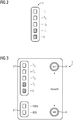
- the display device 1 is in Fig. 2 outlined. It is designed to output a value representing the fill level as a function of the fill level in the tank 6 measured by the measuring device.
- the display device 1 has a discrete scale. "0" represents an empty tank, "1/1" a full one. In between, the fill levels are displayed, for example in "quarter steps".
- the invention is based on the consideration that tank fill levels only change through the use of the connected consumer or active action. Following this consideration, it is only necessary to determine a fill level and update the associated display if the fill level has actually changed.
- analog pointer displays are suitable for this, which in the passive state do not fall back to a starting value, but instead retain the pointer or display position.
- Analog mechanical solutions seem to be fragile and structurally complex.
- Digital display technologies such as bistable LCD (ChLCD), E-lnk, P-lnk and the like can be used for this.
- Electromechanical designs such as flip-dot displays can also be used.
- a movable display part is turned towards or away from the viewer.
- the two halves of the display can be colored differently. What the different display types have in common is that they adopt a display state through active control and then maintain this for a long time even in a voltage-free state.
- the display is permanently updated during normal operation. After the vehicle 5 has been dismantled, the display device 1 is de-energized and the display status remains unchanged. In the disarmed state, the levels of the tanks 6 also remain synchronously unchanged, since the consumers are also de-energized and out of operation.
- the display permanently shows the actual level as long as the level changes only when the power supply is switched on. As a result, water levels can always be read, regardless of the operating state of the vehicle 5.
- additional manual setting buttons 3, 4 can be provided. With these control buttons 3, 4, the display elements 2 and / or 8 are manually brought into the corresponding display state.
- the "full” button - the setting button 3 - is actuated on the display device 1 after a vehicle 5 that has been dismantled and parked is filled.
- An “empty” button is conceivable for updating the display element 2 after the fresh water tank 6 has been emptied when the vehicle 5 has been dismantled and parked.
- this is rarely used, since the emptying of a fresh water tank 6 is usually started from inside the vehicle. You can therefore assume that the power supply is switched on.
- the "empty" key is useful for displaying the waste water tank level.
- Fig. 3 now illustrates an example of the implementation of a display device with level indicators for both the fresh and a waste water tank.
- the display element 2 shows a fill level of the tank 6 for fresh water, the display element 8, however, for the waste water tank.
- the display device therefore comprises a setting button 3 for changing the display content of the display element 2 in order to represent a full fresh water tank, and a setting button 4 for changing the display content of the display element 8 in order to represent an empty waste water tank. If a vehicle is filled or emptied in the disarmed state, the display can be manually set to "full" for the fresh water tank or to "empty" for the waste water tank at these setting buttons 3, 4.
- the display When using the electromechanical display variant, the display is manually moved mechanically to the desired display position by actuating the setting button. A power supply is not necessary.
Landscapes
- Engineering & Computer Science (AREA)
- Mechanical Engineering (AREA)
- Health & Medical Sciences (AREA)
- General Health & Medical Sciences (AREA)
- Biomedical Technology (AREA)
- Environmental & Geological Engineering (AREA)
- Epidemiology (AREA)
- Public Health (AREA)
- Measurement Of Levels Of Liquids Or Fluent Solid Materials (AREA)
- Level Indicators Using A Float (AREA)
- Instrument Panels (AREA)
Abstract
Description
- Die Erfindung betrifft ein spurgebundenes Fahrzeug mit wenigstens einer Messeinrichtung und wenigstens einer Anzeigeeinrichtung zur Anzeige wenigstens eines Messwerts sowie ein Verfahren zum Betreiben des spurgeführten Fahrzeugs.
- Füllstände unterschiedlicher Tanks eines Schienenfahrzeugs werden üblicherweise außen am Fahrzeug angezeigt. Dies können Tanks für Frisch- und Abwasser von WC und Galley sowie von Wasch- und Duschräumen in Reisezugwagen sein. Gleichermaßen können auch die Füllstände von weiteren Tanksystemen, wie z.B. Treibstofftanks, Tanks für eine Scheibenreinigungsanlage etc. von außen ablesbar am Fahrzeug angezeigt werden.
- Der Füllstand des betroffenen Tanks wird mit Sensoren linear oder in Stufen erfasst, in der Mess- und Auswerteelektronik aufbereitet und außen am Fahrzeug mit einer Anzeige ausgegeben.
- Zusätzlich können Füllstände auch an Leit- oder Service zentralen übermittelt werden. Eine typische Anzeige ist die Bandanzeige, in der für das Sanitärmodul die Pegelstände von Frisch- und Abwassertank durch eine Reihe von Leuchtdioden angezeigt werden. Zur Aufrechterhaltung dieser Funktionalität wird eine Spannungsversorgung benötigt.
- Die Kontrolle von Füllständen an abgerüstet abgestellten Fahrzeugen ist ohne weitere Maßnahmen nicht möglich. Zum Ablesen muss, zumindest kurzzeitig, die Elektronik mit Spannung versorgt werden. Eine dauerhafte Spannungsversorgung kommt nicht in Betracht, da diese die Fahrzeugbatterien unerwünscht belasten würden.
- Die
WO 2018/019476 A1 beschreibt hierzu einen Reed-Kontakt, eingerichtet, um bei Anlegung eines Magnetfelds eine Spannungsversorgung für die Füllstandsanzeige und für die Auswerteelektronik des Füllstandmessers zu schalten. - Der Erfindung liegt die Aufgabe zugrunde, die Wartung eines spurgebundenen Fahrzeugs weiter zu vereinfachen.
- Gelöst wird die Aufgabe durch die Gegenstände der unabhängigen Patentansprüche 1 und 9. Weiterbildungen und Ausgestaltungen der Erfindung finden sich in den Merkmalen der abhängigen Patentansprüche wieder.
- Ein erfindungsgemäßes spurgebundenes Fahrzeug, insbesondere ein Schienenfahrzeug des Personenverkehrs, umfasst wenigstens eine Messeinrichtung, umfassend wenigstens einen Messwertaufnehmer zur Erfassung von Messwerten zu einer Messgröße, und wenigstens eine Anzeigeeinrichtung zur Anzeige wenigstens eines Messwerts. Die Anzeigeeinrichtung dient zur optischen Ausgabe wenigstens eines von der Messeinrichtung erfassten Messwert. Der Messwert ist dabei insbesondere aktuell oder zumindest der zuletzt erfasste Messwert. Die Anzeigeeinrichtung weist erfindungsgemäß wenigstens ein bistabiles Anzeigeelement auf, welches den letzten Anzeigeinhalt im spannungsfreien Zustand erhält. Im abgerüsteten, spannungsfreien Zustand wird vom bistabilen Anzeigeelement somit der im aufgerüsteten Zustand zuletzt erfasste Messwert angezeigt.
- Gemäß einer ersten Weiterbildung der Erfindung ist die Anzeigeeinrichtung von außen ablesbar am Fahrzeug angeordnet. Die Anzeigeeinrichtung ist insbesondere an einer Außenseite des Fahrzeugs angeordnet.
- Weitergebildet umfasst die Anzeigeeinrichtung wenigstens ein elektromagnetisch-mechanisches oder ein elektronisches bistabiles Anzeigeelement. Ein Beispiel für ein elektromagnetisch-mechanisches bistabiles Anzeigeelement ist ein sogenanntes Flip-Dot-Display. Als elektronische bistabile Anzeigeelemente sind beispielsweise bistabile Flüssigkristalldisplay (LCD), insbesondere ChLCD, E-Ink- oder P-Ink-Displays bekannt geworden.
- Gemäß einer weiteren Weiterbildung umfasst das spurgebundene Fahrzeug wenigstens einen Tank, insbesondere zur Aufnahme und Speicherung von Fluid, beispielsweise von Frisch-, Grau- oder Abwasser, wobei die Messeinrichtung zur Erfassung eines Füllstands im Tank geeignet ausgebildet und in oder am Tank angeordnet ist. Die Messeinrichtung umfasst somit mindestens einen Messwertaufnehmer zur Erfassung von Messwerten eines Füllstands im Tank. Der Tank ist weitergebildet ein Frisch-, Grau- oder Abwassertank einer Sanitäranlage oder einer Galley des Fahrzeugs. Das Anzeigeelement zeigt entsprechend den Füllstand des Tanks an.
- Eine weitere Weiterbildung der Erfindung ist darin zu sehen, dass das spurgebundene Fahrzeug einen Stelltaster umfasst, welcher im Bereich der Anzeigeeinrichtung angeordnet und mit der Anzeigeeinrichtung in geeigneter Weise verbunden ist und die Anzeigeeinrichtung und der Stelltaster geeignet ausgebildet sind bei Betätigung des Stelltasters einen vorgegebenen Anzeigezustand des bistabilen Anzeigeelements herzustellen.
- Durch Betätigung des Stelltasters wird der Anzeigeinhalt des Anzeigeelements verändert. Stelltaster um Anzeigeeinrichtung sind dabei vorteilhaft ausgebildet, auch im abgerüsteten Zustand des Fahrzeugs und somit bei spannungsfreiem Anzeigeelement, einen vorgegebenen Anzeigezustand des bistabilen Anzeigeelements herzustellen und den angezeigten Anzeigeinhalt zu verändern. Die vorgegebenen Anzeigezustände des Anzeigeelement repräsentieren weitergebildet den Füllstand eines leeren oder eines vollen Tanks oder eines teilgefüllten Tanks.
- Der Stelltaster kann dabei ausgebildet sein, bei Betätigung eine Spannungsversorgung des bistabilen Anzeigeelements herzustellen. Der Stelltaster erzeugt kurzeitig zumindest während der Zeitdauer seiner, beispielsweise manuellen, Betätigung eine Spannung zur Versorgung des bistabilen Anzeigeelements, insbesondere des elektronischen bistabilen Displays auf, um den Anzeigeinhalt zu manipulieren. Dabei kann der Stelltaster ausgebildet und mit der Anzeigeeinrichtung verbunden sein, ausschließlich das Anzeigeelement mit einer Spannung zu versorgen. Nicht versorgt wird dann insbesondere die Messeinrichtung. Bei einem elektromagnetisch-mechanischen bistabilen Anzeigeelement kann der Stelltaster ausgebildet und mit der Anzeigeeinrichtung derart verbunden sein, dass durch Betätigung des Stelltasters eine Kraft auf das Anzeigeelement ausgeübt wird, dieses mechanisch in die gewünschte Anzeigeposition zu bewegen.
- Der Stelltaster ist weitergebildet, in unmittelbarer Umgebung zur Anzeigeeinrichtung auf der Außenseite des Fahrzeugs von außen frei betätigbar angeordnet. Weitergebildet umfasst die Anzeigeeinrichtung den Stelltaster.
- Zum Betreiben eines erfindungsgemäßen spurgebundenen Fahrzeugs wird im aufgerüsteten, betriebsbereiten Zustand des spurgebundenen Fahrzeugs wenigstens ein aktueller Messwert durch die Messeinrichtung erfasst und durch die Anzeigeeinrichtung ausgegeben, insbesondere vom Anzeigeelement angezeigt. Nach einem Abrüsten des spurgebundenen Fahrzeugs und spannungsfreischalten der Anzeigeeinrichtung wird wenigstens ein letzter im aufgerüsteten Zustand des Fahrzeugs erfasster Messwert durch die Anzeigeeinrichtung ausgegeben, insbesondere vom Anzeigeelement angezeigt, so dass dieser im abgerüsteten Zustand des Fahrzeugs abgelesen werden kann.
- Umfasst das spurgebundene Fahrzeug einen Tank und eine Messeinrichtung zur Erfassung eines Messwerts zum Füllstand im Tank, kann der Tank auch im abgerüsteten Zustand des Fahrzeugs befüllt oder entleert werden, beispielsweise in dem Wasser im Tank abgelassen oder abgesaugt wird. Durch, beispielsweise manuelles, Betätigen des Stelltasters kann anschließend ein Anzeigezustand des Anzeigeelement repräsentativ für einen Füllstand eines vollen oder eines leeren Tanks hergestellt werden. Beispielsweise befüllt ein Servicetechniker zunächst den Tank. Nachfolgend betätigt er den entsprechenden Stelltaster, so dass das Anzeigeelement einen vollen Tank anzeigt.
- Die Erfindung ermöglicht die Anzeige von Behälterpegelständen auch bei spannungsfrei abgestellten Fahrzeugen, da die Anzeigeeinrichtung ihren letzten Anzeigeinhalt im spannungsfreien Zustand beibehält. Bei der Kontrolle von Pegelständen können die Messelektrik und die dazugehörige Spannungsversorgung deaktiviert bleiben.
- Der Anzeigeinhalt wird während des normalen Betriebs permanent aktualisiert. Nach Abfallen der Spannungsversorgung erfolgt keine Änderung von Tankpegelständen. Korrespondierend bleibt auch der Anzeigeinhalt unverändert.
- Tankpegelstände werden somit permanent, insbesondere außen am Fahrzeug, angezeigt. Aufwändige Schaltungen zur Aktivierung und späteren Deaktivierung von Messequipment und Anzeige können dabei entfallen. Ebenso entfallen Wege für das Servicepersonal zu innerhalb des Fahrzeugs angeordneten Schaltelementen, an denen die Spannungsversorgung aktiviert werden muss. Wartezeiten bis zur Verfügbarkeit der Information werden überflüssig. Weiterhin verbessert sich der Komfort für das Servicepersonal da auch bei abgerüsteten Fahrzeugen Pegelstände leicht und schnell kontrolliert werden können.
- Die Erfindung lässt zahlreiche Ausführungsformen zu. Sie wird anhand der nachfolgenden Figuren näher erläutert, in denen jeweils ein Ausgestaltungsbeispiel dargestellt ist. Gleiche Elemente in den Figuren sind mit gleichen Bezugszeichen versehen.
- Fig. 1
- zeigt schematisch ein Schienenfahrzeug mit Frischwassertank und einer außen am Fahrzeug angebrachten Anzeigeeinrichtung zur Anzeige des Füllstands,
- Fig. 2
- zeigt eine Anzeigeeinrichtung zur Anzeige des Füllstands,
- Fig. 3
- zeigt eine Anzeigeeinrichtung zur Anzeige des Füllstands mit Stelltastern.
- In
Fig. 1 ist schematisch ein Schienenfahrzeug 5 im Querschnitt dargestellt. Es weist im Dachbereich einen Tank 6 für Frischwasser auf. Im Frischwassertank 6 ist ein Schwimmer 7 als Teil einer Messeinrichtung zur Erfassung des Füllstands im Tank 6 vorgesehen. Auf einer Außenseite des Fahrzeugs 5 ist eine Anzeigeeinrichtung 1 angeordnet. Diese zeigt den von der Messeinrichtung gemessenen Füllstand im Tank 6 so an, dass er von außen ablesbar ist. Die Anzeigeeinrichtung 1 ist inFig. 2 skizziert. Sie ist ausgebildet, in Abhängigkeit des von der Messeinrichtung gemessenen Füllstand im Tank 6 einen den Füllstand repräsentierenden Wert auszugeben. Hier weist die Anzeigeeinrichtung 1 eine diskrete Skala auf. "0" repräsentiert einen leeren Tank, "1/1" einen vollen. Dazwischen werden die Füllstände z.B. in "Viertel-Schritten" angezeigt. - Der Erfindung liegt die Überlegung zu Grunde, dass sich Tankfüllstände nur durch Benutzung der angeschlossenen Verbraucher oder aktives Handeln ändern. Dieser Überlegung folgend, sind das Ermitteln eines Füllstandes und die Aktualisierung der zugehörigen Anzeige nur notwendig, wenn sich der Füllstand tatsächlich geändert hat.
- Bei Schienenfahrzeugen ist zum Betrieb von Verbrauchern meist deren Versorgung mit elektrischer Energie notwendig. Daraus folgt, dass sich nach Abrüsten eines Zuges Tankfüllstände in abgerüstet abgestellten Fahrzeugen nicht mehr ändern.
- Mit einer geeigneten Anzeige kann der letzte, gemessene Füllstand nun ununterbrochen und unverändert ausgegeben werden. Prinzipiell eignen sich dazu analoge Zeigeranzeigen, die im passiven Zustand nicht auf einen Startwert zurückfallen, sondern die Zeiger- oder Anzeigeposition beibehalten. Analogmechanische Lösungen scheinen anfällig und baulich aufwändig zu sein.
- Besser geeignet scheinen bistabile Anzeigeelemente 2 wie in
Figur 3 dargestellt. Dafür kommen digitale Displaytechniken wie z.B. bistabile LCD (ChLCD), E-lnk, P-lnk und ähnliche in Frage. Auch sind elektromechanische Ausführungen wie z.B. Flip-Dot Displays einsetzbar. Bei diesem Anzeigetyp wird ein beweglicher Anzeigeteil dem Betrachter zu- oder abgewandt. Dabei können beispielsweise die beiden Hälften der Anzeige unterschiedlich eingefärbt sein. Den unterschiedlichen Displaytypen gemeinsam ist, dass sie durch aktive Ansteuerung einen Anzeigezustand annehmen und diesen dann auch im spannungsfreien Zustand langfristig beibehalten. - Die Anzeige wird während des normalen Betriebes permanent aktuell gehalten. Nach Abrüsten des Fahrzeuges 5 wird das die Anzeigeeinrichtung 1 spannungsfrei geschaltet und der Anzeigezustand bleibt unverändert erhalten. Im abgerüsteten Zustand bleiben synchron auch die Pegelstände der Tanks 6 unverändert, da die Verbraucher ebenfalls spannungsfrei und außer Betrieb sind. Die Anzeige gibt also permanent den tatsächlichen Pegelstand an, solange Pegeländerungen nur bei eingeschalteter Spannungsversorgung erfolgen. Dadurch sind Pegelstände, unabhängig vom Betriebszustand des Fahrzeuges 5, immer ablesbar.
- Um auch Befüll- oder Entleerungsvorgänge an abgerüstet abgestellten Fahrzeugen 5 akkurat zu erfassen, können zusätzliche manuelle Stelltaster 3, 4 vorgesehen sein. Mit diesen Stelltastern 3, 4 werden die Anzeigeelemente 2 und/oder 8 manuell in den entsprechenden Anzeigezustand gebracht. Dazu wird an der Anzeigeeinrichtung 1 nach dem Befüllen eines abgerüstet abgestellten Fahrzeuges 5 die "voll" Taste - der Stelltaster 3 - betätigt. Für die Aktualisierung des Anzeigeelements 2 nach einer Entleerung des Frischwassertanks 6 bei abgerüstet abgestelltem Fahrzeug 5 ist eine "leer"-Taste denkbar. Diese wird jedoch eher selten genutzt werden, da die Entleerung eines Frischwassertanks 6 üblicherweise aus dem Fahrzeuginneren gestartet wird. Dabei kann man also von einer eingeschalteten Spannungsversorgung ausgehen. Bei Abwassertanks mit Absaugung von außen ist hingegen die "leer"-Taste für die Anzeige des Abwassertankpegels sinnvoll.
-
Fig. 3 veranschaulicht nun ein Beispiel für die Umsetzung einer Anzeigeeinrichtung mit Füllstandanzeigen sowohl für den Frisch-, als auch für einen Abwassertank. Das Anzeigeelement 2 zeigt einen Füllstand des Tanks 6 für Frischwasser an, das Anzeigeelement 8 hingegen für den Abwassertank. Die Anzeigeeinrichtung umfasst fürderhin einen Stelltaster 3 zur Änderung des Anzeigeeinhalts des Anzeigeelements 2, um einen vollen Frischwassertank zu repräsentieren, sowie einen Stelltaster 4 zur Änderung des Anzeigeeinhalts des Anzeigeelements 8, um einen leeren Abwassertank zu repräsentieren. Falls ein Fahrzeug im abgerüsteten Zustand befüllt oder entleert wird, kann an diesen Stelltastern 3, 4 die Anzeige manuell für den Frischwassertank auf "voll" bzw. für den Abwassertank auf "leer" gestellt werden. - Dazu ist bei Einsatz der elektronischen Displayvariante eine kurzzeitige Spannungsversorgung des Anzeigepanels notwendig. Durch die Stelltasterbetätigung wird lediglich das Display mit Spannung versorgt und die entsprechende Anzeige auf den neuen Wert gestellt. Ein Start der Mess- und Auswerteelektronik ist nicht notwendig.
- Bei Einsatz der elektromechanischen Displayvariante wird durch die Betätigung der Stelltaster das Display manuell mechanisch in die gewünschte Anzeigeposition bewegt. Eine Spannungsversorgung ist nicht notwendig.
Claims (10)
- Spurgebundenes Fahrzeug mit wenigstens einer Messeinrichtung und wenigstens einer Anzeigeeinrichtung zur Anzeige wenigstens eines Messwerts,
dadurch gekennzeichnet, dass
die Anzeigeeinrichtung wenigstens ein bistabiles Anzeigeelement umfasst. - Spurgebundenes Fahrzeug nach Anspruch 1,
dadurch gekennzeichnet, dass
die Anzeigeeinrichtung von außen ablesbar am Fahrzeug angeordnet ist. - Spurgebundenes Fahrzeug nach einem der Ansprüche 1 oder 2,
dadurch gekennzeichnet, dass
die Anzeigeeinrichtung wenigstens ein elektromagnetisch-mechanisches oder wenigstens ein elektronisches bistabiles Anzeigeelement umfasst. - Spurgebundenes Fahrzeug nach einem der Ansprüche 1 bis 3,
dadurch gekennzeichnet, dass
es wenigstens einen Tank umfasst, wobei die Messeinrichtung zur Erfassung eines Füllstands im Tank geeignet ausgebildet und angeordnet ist. - Spurgebundenes Fahrzeug nach Anspruch 4,
dadurch gekennzeichnet, dass
der Tank ein Frisch-, Grau- oder Abwassertank einer Sanitäranlage oder einer Galley des Fahrzeugs ist. - Spurgebundenes Fahrzeug nach einem der Ansprüche 1 bis 5,
dadurch gekennzeichnet, dass
es einen Stelltaster umfasst, welcher im Bereich der Anzeigeeinrichtung angeordnet und mit der Anzeigeeinrichtung verbunden ist, wobei die Anzeigeeinrichtung und der Stelltaster geeignet ausgebildet sind, bei Betätigung des Stelltasters einen vorgegebenen Anzeigezustand des bistabilen Anzeigeelements herzustellen. - Spurgebundenes Fahrzeug nach Anspruch 6,
dadurch gekennzeichnet, dass
der Stelltaster ausgebildet ist, bei Betätigung eine Spannungsversorgung des bistabilen Anzeigeelements herzustellen. - Spurgebundenes Fahrzeug nach einem der Ansprüche 6 oder 7,
dadurch gekennzeichnet, dass
die vorgegebenen Anzeigezustände den Füllstand eines leeren oder eines vollen Tanks repräsentieren. - Verfahren zum Betreiben eines spurgebundenen Fahrzeugs nach einem der Ansprüche 1 bis 8,
gekennzeichnet durch folgende Verfahrensschritte:a. Erfassen wenigstens eines Messwerts durch die Messeinrichtung;b. Anzeigen wenigstens eines aktuellen Messwerts durch die Anzeigeeinrichtung;c. Abrüsten des spurgebundenen Fahrzeugs und Spannungsfreischalten der Anzeigeeinrichtung;d. Anzeigen wenigstens eines letzten, im aufgerüsteten Zustand des Fahrzeugs erfassten Messwerts durch die Anzeigeeinrichtung. - Verfahren nach Anspruch 9 zum Betreiben eines spurgebundenen Fahrzeugs nach den Ansprüchen 4 und 6, gekennzeichnet durch folgende Verfahrensschritte:a. Befüllen oder Entleeren des Tanks im abgerüsteten Zustand des spurgebundenen Fahrzeugs;b. Betätigen des Stelltasters zur Herstellung eines Anzeigezustands des Anzeigeelements repräsentativ für einen Füllstand eines vollen oder eines leeren Tanks.
Applications Claiming Priority (1)
| Application Number | Priority Date | Filing Date | Title |
|---|---|---|---|
| DE102019209478.3A DE102019209478A1 (de) | 2019-06-28 | 2019-06-28 | Anzeige für Tankfüllstände mit bistabilem Anzeigeelement |
Publications (2)
| Publication Number | Publication Date |
|---|---|
| EP3756970A1 true EP3756970A1 (de) | 2020-12-30 |
| EP3756970B1 EP3756970B1 (de) | 2025-04-09 |
Family
ID=70918251
Family Applications (1)
| Application Number | Title | Priority Date | Filing Date |
|---|---|---|---|
| EP20176974.2A Active EP3756970B1 (de) | 2019-06-28 | 2020-05-28 | Spurgebundenes fahrzeug und verfahren zum betreiben desselben |
Country Status (4)
| Country | Link |
|---|---|
| EP (1) | EP3756970B1 (de) |
| DE (1) | DE102019209478A1 (de) |
| ES (1) | ES3033468T3 (de) |
| PL (1) | PL3756970T3 (de) |
Citations (5)
| Publication number | Priority date | Publication date | Assignee | Title |
|---|---|---|---|---|
| WO1997046435A1 (de) * | 1996-06-04 | 1997-12-11 | Siemens Sgp Verkehrstechnik Gmbh | Verfahren zur kontrollierten teilentleerung eines abwasserbehälters in einem fahrzeug, insbesondere schienenfahrzeug sowie einrichtung zur durchführung des verfahrens |
| US20100117817A1 (en) * | 2008-11-12 | 2010-05-13 | Stemco Lp | On-board low-power vehicle condition indicator |
| DE102009034432A1 (de) * | 2009-07-23 | 2011-01-27 | Volkswagen Ag | Anzeige für ein Fahrzeug und entsprechendes Fahrzeug |
| US20160351927A1 (en) * | 2014-02-12 | 2016-12-01 | Intelligent Energy Limited | Fuel source, fuel cell system and associated method |
| DE102016213898A1 (de) * | 2016-07-28 | 2018-02-01 | Siemens Aktiengesellschaft | Fahrzeug mit Anzeigepanel zum Ablesen von Füllständen |
Family Cites Families (1)
| Publication number | Priority date | Publication date | Assignee | Title |
|---|---|---|---|---|
| WO2017056481A1 (ja) * | 2015-09-30 | 2017-04-06 | パナソニックIpマネジメント株式会社 | 検知装置および検知システム |
-
2019
- 2019-06-28 DE DE102019209478.3A patent/DE102019209478A1/de not_active Ceased
-
2020
- 2020-05-28 PL PL20176974.2T patent/PL3756970T3/pl unknown
- 2020-05-28 EP EP20176974.2A patent/EP3756970B1/de active Active
- 2020-05-28 ES ES20176974T patent/ES3033468T3/es active Active
Patent Citations (6)
| Publication number | Priority date | Publication date | Assignee | Title |
|---|---|---|---|---|
| WO1997046435A1 (de) * | 1996-06-04 | 1997-12-11 | Siemens Sgp Verkehrstechnik Gmbh | Verfahren zur kontrollierten teilentleerung eines abwasserbehälters in einem fahrzeug, insbesondere schienenfahrzeug sowie einrichtung zur durchführung des verfahrens |
| US20100117817A1 (en) * | 2008-11-12 | 2010-05-13 | Stemco Lp | On-board low-power vehicle condition indicator |
| DE102009034432A1 (de) * | 2009-07-23 | 2011-01-27 | Volkswagen Ag | Anzeige für ein Fahrzeug und entsprechendes Fahrzeug |
| US20160351927A1 (en) * | 2014-02-12 | 2016-12-01 | Intelligent Energy Limited | Fuel source, fuel cell system and associated method |
| DE102016213898A1 (de) * | 2016-07-28 | 2018-02-01 | Siemens Aktiengesellschaft | Fahrzeug mit Anzeigepanel zum Ablesen von Füllständen |
| WO2018019476A1 (de) | 2016-07-28 | 2018-02-01 | Siemens Aktiengesellschaft | Fahrzeug mit anzeigepanel zum ablesen von füllständen |
Also Published As
| Publication number | Publication date |
|---|---|
| ES3033468T3 (en) | 2025-08-04 |
| PL3756970T3 (pl) | 2025-08-04 |
| EP3756970B1 (de) | 2025-04-09 |
| DE102019209478A1 (de) | 2020-12-31 |
Similar Documents
| Publication | Publication Date | Title |
|---|---|---|
| DE2515202C3 (de) | Digitale Vielfachmeßeinrichtung | |
| DE3246269A1 (de) | Verfahren und einrichtung zur elektronischen leckpruefung | |
| EP0191413A2 (de) | Fahrtschreiber für Kraftfahrzeuge | |
| DE2157863C3 (de) | Flfissigkeitsvorratsmeß- und Anzeigesystem | |
| DE2521100A1 (de) | Vorrichtung zur gewichtsmessung von abgegebenen fluessigkeiten | |
| DE102019111573A1 (de) | Diagnose des schalters im geöffneten zustand für eine taste, die drei oder mehr schalter betätigt | |
| DE3133239C2 (de) | ||
| EP3756970B1 (de) | Spurgebundenes fahrzeug und verfahren zum betreiben desselben | |
| DE3247910C2 (de) | ||
| EP1175535B1 (de) | Vorrichtung zur aufnahme von aufsaugbarem material | |
| EP3465106B1 (de) | Fahrzeug mit anzeigepanel zum ablesen von füllständen | |
| DE2630033A1 (de) | Entladungszustandsanzeiger | |
| DE102005055092A1 (de) | Füllstandsanzeigesystem | |
| DE3315188C2 (de) | ||
| DE102020134409B3 (de) | Zwischeneinheit für ein Feldgerät mit einem Energiespeicher und Verfahren | |
| DE3125526C2 (de) | Anzeigevorrichtung für Meßinstrumente | |
| EP3904177B1 (de) | Zustandsüberwachung einer sanitärzelle für ein fahrzeug | |
| DE102008012953A1 (de) | Überprüfung von Anzeigesystemen in Schienenfahrzeugen | |
| DE19526454C1 (de) | Wegstreckenzähleinrichtung mit Zählerrücksetzfunktion für ein Fahrzeug | |
| DE60312251T2 (de) | Verfahren und Vorrichtung zur Diagnose des Volumenzählers | |
| DE102019213429A1 (de) | Verfahren zur Bestimmung einer Wassertankvorhaltezeit und Nasszelle | |
| EP1788463A2 (de) | Anzeigeeinheit für die Prozessautomatisierungstechnik | |
| EP4552508A1 (de) | Getränkesprudler | |
| DE102009037497A1 (de) | Diagnosevorrichtung für schlüsselloses Zugangssystem | |
| DE102020134408A1 (de) | Bedieneinheit für Feldgeräte mit einem Energiespeicher und ein zugehöriges Feldgerät |
Legal Events
| Date | Code | Title | Description |
|---|---|---|---|
| PUAI | Public reference made under article 153(3) epc to a published international application that has entered the european phase |
Free format text: ORIGINAL CODE: 0009012 |
|
| STAA | Information on the status of an ep patent application or granted ep patent |
Free format text: STATUS: THE APPLICATION HAS BEEN PUBLISHED |
|
| AK | Designated contracting states |
Kind code of ref document: A1 Designated state(s): AL AT BE BG CH CY CZ DE DK EE ES FI FR GB GR HR HU IE IS IT LI LT LU LV MC MK MT NL NO PL PT RO RS SE SI SK SM TR |
|
| AX | Request for extension of the european patent |
Extension state: BA ME |
|
| STAA | Information on the status of an ep patent application or granted ep patent |
Free format text: STATUS: REQUEST FOR EXAMINATION WAS MADE |
|
| 17P | Request for examination filed |
Effective date: 20210630 |
|
| RBV | Designated contracting states (corrected) |
Designated state(s): AL AT BE BG CH CY CZ DE DK EE ES FI FR GB GR HR HU IE IS IT LI LT LU LV MC MK MT NL NO PL PT RO RS SE SI SK SM TR |
|
| STAA | Information on the status of an ep patent application or granted ep patent |
Free format text: STATUS: EXAMINATION IS IN PROGRESS |
|
| 17Q | First examination report despatched |
Effective date: 20220802 |
|
| GRAP | Despatch of communication of intention to grant a patent |
Free format text: ORIGINAL CODE: EPIDOSNIGR1 |
|
| STAA | Information on the status of an ep patent application or granted ep patent |
Free format text: STATUS: GRANT OF PATENT IS INTENDED |
|
| RIC1 | Information provided on ipc code assigned before grant |
Ipc: G01F 23/38 20060101ALN20241118BHEP Ipc: B61D 35/00 20060101ALI20241118BHEP Ipc: B61D 41/00 20060101ALI20241118BHEP Ipc: G01F 23/00 20060101ALI20241118BHEP Ipc: B61L 15/00 20060101AFI20241118BHEP |
|
| RIC1 | Information provided on ipc code assigned before grant |
Ipc: G01F 23/38 20060101ALN20241126BHEP Ipc: B61D 35/00 20060101ALI20241126BHEP Ipc: B61D 41/00 20060101ALI20241126BHEP Ipc: G01F 23/00 20060101ALI20241126BHEP Ipc: B61L 15/00 20060101AFI20241126BHEP |
|
| INTG | Intention to grant announced |
Effective date: 20241204 |
|
| GRAS | Grant fee paid |
Free format text: ORIGINAL CODE: EPIDOSNIGR3 |
|
| GRAA | (expected) grant |
Free format text: ORIGINAL CODE: 0009210 |
|
| STAA | Information on the status of an ep patent application or granted ep patent |
Free format text: STATUS: THE PATENT HAS BEEN GRANTED |
|
| AK | Designated contracting states |
Kind code of ref document: B1 Designated state(s): AL AT BE BG CH CY CZ DE DK EE ES FI FR GB GR HR HU IE IS IT LI LT LU LV MC MK MT NL NO PL PT RO RS SE SI SK SM TR |
|
| REG | Reference to a national code |
Ref country code: GB Ref legal event code: FG4D Free format text: NOT ENGLISH |
|
| REG | Reference to a national code |
Ref country code: CH Ref legal event code: EP |
|
| REG | Reference to a national code |
Ref country code: DE Ref legal event code: R096 Ref document number: 502020010779 Country of ref document: DE |
|
| REG | Reference to a national code |
Ref country code: IE Ref legal event code: FG4D Free format text: LANGUAGE OF EP DOCUMENT: GERMAN |
|
| PGFP | Annual fee paid to national office [announced via postgrant information from national office to epo] |
Ref country code: GB Payment date: 20250610 Year of fee payment: 6 |
|
| PGFP | Annual fee paid to national office [announced via postgrant information from national office to epo] |
Ref country code: FR Payment date: 20250516 Year of fee payment: 6 |
|
| REG | Reference to a national code |
Ref country code: ES Ref legal event code: FG2A Ref document number: 3033468 Country of ref document: ES Kind code of ref document: T3 Effective date: 20250804 |
|
| REG | Reference to a national code |
Ref country code: NL Ref legal event code: MP Effective date: 20250409 |
|
| REG | Reference to a national code |
Ref country code: DE Ref legal event code: R081 Ref document number: 502020010779 Country of ref document: DE Owner name: SIEMENS MOBILITY GMBH, DE Free format text: FORMER OWNER: SIEMENS MOBILITY GMBH, 81739 MUENCHEN, DE |
|
| PG25 | Lapsed in a contracting state [announced via postgrant information from national office to epo] |
Ref country code: NL Free format text: LAPSE BECAUSE OF FAILURE TO SUBMIT A TRANSLATION OF THE DESCRIPTION OR TO PAY THE FEE WITHIN THE PRESCRIBED TIME-LIMIT Effective date: 20250409 |
|
| RAP4 | Party data changed (patent owner data changed or rights of a patent transferred) |
Owner name: SIEMENS MOBILITY GMBH |
|
| PG25 | Lapsed in a contracting state [announced via postgrant information from national office to epo] |
Ref country code: FI Free format text: LAPSE BECAUSE OF FAILURE TO SUBMIT A TRANSLATION OF THE DESCRIPTION OR TO PAY THE FEE WITHIN THE PRESCRIBED TIME-LIMIT Effective date: 20250409 Ref country code: PT Free format text: LAPSE BECAUSE OF FAILURE TO SUBMIT A TRANSLATION OF THE DESCRIPTION OR TO PAY THE FEE WITHIN THE PRESCRIBED TIME-LIMIT Effective date: 20250811 |
|
| PGFP | Annual fee paid to national office [announced via postgrant information from national office to epo] |
Ref country code: ES Payment date: 20250825 Year of fee payment: 6 |
|
| PGFP | Annual fee paid to national office [announced via postgrant information from national office to epo] |
Ref country code: DE Payment date: 20250718 Year of fee payment: 6 |
|
| REG | Reference to a national code |
Ref country code: LT Ref legal event code: MG9D |
|
| PG25 | Lapsed in a contracting state [announced via postgrant information from national office to epo] |
Ref country code: NO Free format text: LAPSE BECAUSE OF FAILURE TO SUBMIT A TRANSLATION OF THE DESCRIPTION OR TO PAY THE FEE WITHIN THE PRESCRIBED TIME-LIMIT Effective date: 20250709 Ref country code: GR Free format text: LAPSE BECAUSE OF FAILURE TO SUBMIT A TRANSLATION OF THE DESCRIPTION OR TO PAY THE FEE WITHIN THE PRESCRIBED TIME-LIMIT Effective date: 20250710 |
|
| PGFP | Annual fee paid to national office [announced via postgrant information from national office to epo] |
Ref country code: IT Payment date: 20250610 Year of fee payment: 6 Ref country code: PL Payment date: 20250529 Year of fee payment: 6 |
|
| PG25 | Lapsed in a contracting state [announced via postgrant information from national office to epo] |
Ref country code: BG Free format text: LAPSE BECAUSE OF FAILURE TO SUBMIT A TRANSLATION OF THE DESCRIPTION OR TO PAY THE FEE WITHIN THE PRESCRIBED TIME-LIMIT Effective date: 20250409 |
|
| PG25 | Lapsed in a contracting state [announced via postgrant information from national office to epo] |
Ref country code: HR Free format text: LAPSE BECAUSE OF FAILURE TO SUBMIT A TRANSLATION OF THE DESCRIPTION OR TO PAY THE FEE WITHIN THE PRESCRIBED TIME-LIMIT Effective date: 20250409 |
|
| PGFP | Annual fee paid to national office [announced via postgrant information from national office to epo] |
Ref country code: CH Payment date: 20250812 Year of fee payment: 6 |
|
| PG25 | Lapsed in a contracting state [announced via postgrant information from national office to epo] |
Ref country code: RS Free format text: LAPSE BECAUSE OF FAILURE TO SUBMIT A TRANSLATION OF THE DESCRIPTION OR TO PAY THE FEE WITHIN THE PRESCRIBED TIME-LIMIT Effective date: 20250709 |
|
| PG25 | Lapsed in a contracting state [announced via postgrant information from national office to epo] |
Ref country code: IS Free format text: LAPSE BECAUSE OF FAILURE TO SUBMIT A TRANSLATION OF THE DESCRIPTION OR TO PAY THE FEE WITHIN THE PRESCRIBED TIME-LIMIT Effective date: 20250809 |
|
| PG25 | Lapsed in a contracting state [announced via postgrant information from national office to epo] |
Ref country code: LV Free format text: LAPSE BECAUSE OF FAILURE TO SUBMIT A TRANSLATION OF THE DESCRIPTION OR TO PAY THE FEE WITHIN THE PRESCRIBED TIME-LIMIT Effective date: 20250409 |
|
| REG | Reference to a national code |
Ref country code: DE Ref legal event code: R097 Ref document number: 502020010779 Country of ref document: DE |
|
| PG25 | Lapsed in a contracting state [announced via postgrant information from national office to epo] |
Ref country code: DK Free format text: LAPSE BECAUSE OF FAILURE TO SUBMIT A TRANSLATION OF THE DESCRIPTION OR TO PAY THE FEE WITHIN THE PRESCRIBED TIME-LIMIT Effective date: 20250409 Ref country code: SM Free format text: LAPSE BECAUSE OF FAILURE TO SUBMIT A TRANSLATION OF THE DESCRIPTION OR TO PAY THE FEE WITHIN THE PRESCRIBED TIME-LIMIT Effective date: 20250409 |
|
| PG25 | Lapsed in a contracting state [announced via postgrant information from national office to epo] |
Ref country code: LU Free format text: LAPSE BECAUSE OF NON-PAYMENT OF DUE FEES Effective date: 20250528 |
|
| PG25 | Lapsed in a contracting state [announced via postgrant information from national office to epo] |
Ref country code: CZ Free format text: LAPSE BECAUSE OF FAILURE TO SUBMIT A TRANSLATION OF THE DESCRIPTION OR TO PAY THE FEE WITHIN THE PRESCRIBED TIME-LIMIT Effective date: 20250409 |
|
| PG25 | Lapsed in a contracting state [announced via postgrant information from national office to epo] |
Ref country code: EE Free format text: LAPSE BECAUSE OF FAILURE TO SUBMIT A TRANSLATION OF THE DESCRIPTION OR TO PAY THE FEE WITHIN THE PRESCRIBED TIME-LIMIT Effective date: 20250409 |
|
| PG25 | Lapsed in a contracting state [announced via postgrant information from national office to epo] |
Ref country code: SK Free format text: LAPSE BECAUSE OF FAILURE TO SUBMIT A TRANSLATION OF THE DESCRIPTION OR TO PAY THE FEE WITHIN THE PRESCRIBED TIME-LIMIT Effective date: 20250409 Ref country code: RO Free format text: LAPSE BECAUSE OF FAILURE TO SUBMIT A TRANSLATION OF THE DESCRIPTION OR TO PAY THE FEE WITHIN THE PRESCRIBED TIME-LIMIT Effective date: 20250409 |
|
| REG | Reference to a national code |
Ref country code: BE Ref legal event code: MM Effective date: 20250531 |
|
| PG25 | Lapsed in a contracting state [announced via postgrant information from national office to epo] |
Ref country code: MC Free format text: LAPSE BECAUSE OF FAILURE TO SUBMIT A TRANSLATION OF THE DESCRIPTION OR TO PAY THE FEE WITHIN THE PRESCRIBED TIME-LIMIT Effective date: 20250409 |
|
| PLBE | No opposition filed within time limit |
Free format text: ORIGINAL CODE: 0009261 |
|
| STAA | Information on the status of an ep patent application or granted ep patent |
Free format text: STATUS: NO OPPOSITION FILED WITHIN TIME LIMIT |
|
| REG | Reference to a national code |
Ref country code: CH Ref legal event code: L10 Free format text: ST27 STATUS EVENT CODE: U-0-0-L10-L00 (AS PROVIDED BY THE NATIONAL OFFICE) Effective date: 20260218 |
|
| 26N | No opposition filed |
Effective date: 20260112 |
|
| PG25 | Lapsed in a contracting state [announced via postgrant information from national office to epo] |
Ref country code: IE Free format text: LAPSE BECAUSE OF NON-PAYMENT OF DUE FEES Effective date: 20250528 |
|
| PG25 | Lapsed in a contracting state [announced via postgrant information from national office to epo] |
Ref country code: BE Free format text: LAPSE BECAUSE OF NON-PAYMENT OF DUE FEES Effective date: 20250531 |