EP3756511B1 - Kühlmöbel mit ventilationsvorrichtung - Google Patents
Kühlmöbel mit ventilationsvorrichtung Download PDFInfo
- Publication number
- EP3756511B1 EP3756511B1 EP20173506.5A EP20173506A EP3756511B1 EP 3756511 B1 EP3756511 B1 EP 3756511B1 EP 20173506 A EP20173506 A EP 20173506A EP 3756511 B1 EP3756511 B1 EP 3756511B1
- Authority
- EP
- European Patent Office
- Prior art keywords
- refrigeration cabinet
- fan
- removal side
- cabinet
- refrigeration
- Prior art date
- Legal status (The legal status is an assumption and is not a legal conclusion. Google has not performed a legal analysis and makes no representation as to the accuracy of the status listed.)
- Active
Links
Images

Classifications
-
- A—HUMAN NECESSITIES
- A47—FURNITURE; DOMESTIC ARTICLES OR APPLIANCES; COFFEE MILLS; SPICE MILLS; SUCTION CLEANERS IN GENERAL
- A47F—SPECIAL FURNITURE, FITTINGS, OR ACCESSORIES FOR SHOPS, STOREHOUSES, BARS, RESTAURANTS OR THE LIKE; PAYING COUNTERS
- A47F3/00—Show cases or show cabinets
- A47F3/04—Show cases or show cabinets air-conditioned, refrigerated
- A47F3/0439—Cases or cabinets of the open type
- A47F3/0443—Cases or cabinets of the open type with forced air circulation
- A47F3/0447—Cases or cabinets of the open type with forced air circulation with air curtains
Definitions
- the invention relates to a refrigeration unit for reducing an accumulation of cooled air flowing out of the refrigeration unit in an area close to the floor in front of the refrigeration unit, as well as to an associated refrigeration unit.
- Refrigeration cabinets are used in supermarkets, for example, to offer chilled or frozen products. Chilled products in particular are preferably presented and taken by customers via an open side, i.e. one that cannot be covered by a door or the like. A constant flow of liquid enters the open side, which is directed towards the customer. Part of the cooled air escapes from the refrigerated cabinet and collects in the area near the floor in front of the refrigerated cabinet. In this regard, it is negative that customers stand in exactly this area while they select the products to be taken. The accumulation of cold air on the feet and legs is perceived as unpleasant and shortens the time spent at the refrigerated cabinet, which limits the achievable sales of the refrigerated cabinet operator.
- baffles are sometimes used to influence the air flow, for example on the shelves of the refrigerated cabinets, but these only have a small positive effect. Closing the removal side with doors is an alternative option, but this is not considered practical by the refrigerated cabinet operators and also by many customers.
- Printed prior art in the present technical field is available, for example, from the documents DE 20 2018 102 902 U , US 2017/150829 A1 and FR 2 160 771 A1 known.
- the invention is therefore based on the object of providing a device with which an accumulation of cooled air in the area close to the floor in front of refrigerated cabinets with an open removal side facing the customer can be significantly reduced.
- a refrigeration unit comprising a housing, a cooling chamber for receiving items to be cooled with an open removal side, a circulation channel running continuously between the housing and the cooling chamber, in which the fan is arranged, which is designed to generate the circulation flow around the cooling chamber and across the open removal side.
- the circulation channel has an inlet and an outlet on the removal side, which are aligned facing each other, wherein a ventilation device for the cooling chamber, which is open at least on one removal side or can be opened via a door, is provided on the refrigeration unit.
- Refrigeration cabinet for reducing the accumulation of cooled air flowing out of the refrigeration cabinet in an area close to the floor in front of the refrigeration cabinet on its open removal side.
- the ventilation device comprises at least one fan, which is preferably arranged in a refrigeration cabinet top area opposite the area close to the floor.
- the at least one fan is designed and aligned to suck in air from the refrigeration cabinet top area or the area close to the floor and to blow it out in a central blow-out direction at a horizontal angle ⁇ with respect to a front plane parallel to the removal side along the refrigeration cabinet and at a vertical angle ⁇ with respect to a top plane parallel to the top of the refrigeration cabinet and perpendicular to the front plane.
- the angle range for the horizontal angle is between 20° and 70° or between -20 and -70°, depending on the direction in which the air is blown out relative to the refrigeration cabinet.
- the angle range for the vertical angle is between 20° and 70°, with the blow-out direction always being upwards in a direction away from the area close to the floor.
- the at least one fan in the upper area of the refrigerated cabinet creates a flow vortex around the refrigerated cabinet, particularly in the area close to the floor in front of the removal side of the refrigerated cabinet, which reduces the accumulation of cold air escaping from the refrigerated cabinet.
- the effect is particularly advantageous if the following applies to the angles ⁇ and ⁇ : 35° ⁇ , ⁇ 50° or alternatively -35° ⁇ -50° and 35° ⁇ 50°.
- Freezers or refrigerators loaded on top of the open refrigerated cabinets are often positioned so that the flow generated by the at least one fan creates a vortex or a circulating flow around the freezer or refrigerator, which simultaneously removes the cold air in front of the refrigerated cabinet.
- the horizontal angle ⁇ is given with positive and negative angle ranges because the alignment depends on the main direction in which customers move along the refrigerated cabinet, e.g. clockwise or anti-clockwise.
- the alignment is such that the blowing direction is in the direction of movement, so that the customer does not feel any flow from the front or diagonally in front.
- a variant of the ventilation device provides that the at least one fan has a blow-out duct which is integrated into the fan or connected to it.
- the ventilation device further comprises a separating element which separates a suction area and a blow-out area of the fan in terms of flow.
- the at least one fan sucks in air from the suction area and blows it out on the removal side of the refrigerated cabinet.
- the separating element serves on the one hand as a separation for the flow of the at least one fan, and on the other hand as a visual barrier, since the at least one fan is positioned behind the separating element in the rear area of the refrigerated cabinet.
- the dividing element is designed to extend over an entire length of an opening width of the removal side of the refrigerated cabinet.
- the dividing element extends over the entire length of the refrigerated cabinet if its dimensions are defined as length, depth from the removal side to the back and vertical height.
- the ventilation device provides that the at least one fan is held fastened to the separating element.
- the separating element then takes on the further task of serving as a fastening device for the at least one fan and can be pre-assembled as a structural unit and attached to the refrigerated cabinet.
- the separating element has several sections that run at an angle to one another.
- the at least one fan is preferably attached to one of the sections, with this section determining the vertical angle ⁇ .
- the alignment of the blow-out direction at the vertical angle ⁇ is thus determined in a simple manner via the section of the separating element.
- the ventilation device is preferably provided with several fans in arranged in a row and aligned identically to blow at the same horizontal and vertical angle. The effectiveness of this in solving the problem is further improved. In addition, the speed of each individual fan can be reduced to limit the noise generated.
- the fans are designed as radial fans.
- a suction device is also provided according to the invention.
- a suction device is proposed for the refrigerated cabinet that is open at least on the removal side to reduce the accumulation of cooled air flowing out of the refrigerated cabinet in an area close to the floor in front of the refrigerated cabinet on its open removal side, with a continuous suction channel and at least one fan of the ventilation device arranged on the suction channel to generate a suction flow.
- the suction channel has a suction opening and a blow-out opening.
- suction opening is directed towards the area near the floor in front of the refrigerated cabinet
- blow-out opening is directed towards an area on the top of the refrigerated cabinet opposite the area near the floor, so that the cooled air flowing out of the refrigerated cabinet can be sucked out from the area near the floor and blown out onto the area on the top of the refrigerated cabinet.
- the extraction device generates the extraction flow via the fan(s) of the ventilation device and sucks the air escaping from the refrigerated cabinet before it collects in the area near the floor in front of the refrigerated cabinet as a kind of "lake of cold air" in which the customers would have to stand.
- the extraction flow is blown out in the area of the top of the refrigerated cabinet by the ventilation device as described above.
- the suction device can be integrated into the refrigeration unit or arranged on the refrigeration unit, in particular a design is preferred in which the suction channel is partially formed through the refrigeration unit
- the refrigerated cabinets comprise a housing that encloses the cooling chamber except for the open removal side.
- the extraction channel is preferably installed along this housing so that the extraction flow is guided around the refrigerated cabinet on the outside along the bottom and rear wall of the housing.
- the suction opening of the extraction channel preferably points towards the open removal side and in the direction of the area near the floor in front of the refrigerated cabinet.
- the waste heat-generating components of the thermal cycle are arranged on the rear side of the refrigeration unit. It is advantageous to design the extraction device in which the extraction channel is guided along the waste heat-generating components, so that the extraction flow characterized by cooled air can be guided past the waste heat-generating components and the efficiency of the refrigeration unit can therefore be improved.
- the suction via the suction opening of the extraction duct is positively influenced if its central alignment is at an angle of 20-60°, especially 25-45°, to a vertical height direction of the refrigerated cabinet. This means that the cold air flow coming out of the open extraction side can be extracted immediately before it collects in the area near the floor in front of the refrigerated cabinet.
- the special alignment promotes the supply of the cold air flow into the suction duct and at the same time ensures that air from the area near the floor is also constantly sucked in, so that any accumulations of cold air in front of the refrigerated cabinet caused by external influences, for example when filling the refrigerated cabinet, can also be dissolved.
- the extraction device further comprises a control and a temperature sensor.
- the temperature sensor is preferably placed on or in the extraction duct in order to measure the temperature of the extraction flow.
- the extraction flow conveyed by the fan can be adjusted via the control depending on a measured temperature value of the extraction flow and thus the air in the area near the floor in front of the refrigerated cabinet.
- the invention also includes the method for reducing the accumulation of cooled air flowing out of a refrigerated cabinet in the area near the floor in front of the refrigerated cabinet on its open removal side, wherein the suction flow is generated by means of the suction device, via which cooled air flowing out of the refrigerated cabinet is sucked out of the area near the floor and blown out by the ventilation device on the upper side of the refrigerated cabinet.
- a fan In the case of refrigerated cabinets with an open removal side, a fan is used to generate a circulation flow along the removal side facing the customer and around the housing of the refrigerated cabinet that defines the cooling chamber.
- the circulation flow can be guided through a heat exchanger and serve as cooling air for the cooling chambers.
- the fan can only ever convey a certain volume flow and there is also air exchange with ambient air in the area of the open removal side, a certain amount of cooled air always escapes from the refrigerated cabinet and would collect in front of the refrigerated cabinet without the method.
- the method also preferably provides that the extraction flow runs at least in sections parallel to the circulation flow of the refrigerated cabinet generated by the fan.
- the extraction channel is guided along waste heat-generating components of the thermal cycle of the refrigeration appliance and the extraction flow flows along the waste heat-generating components or flows over the waste heat-generating components.
- the method is characterized in that the suction flow is regulated with respect to its volume flow via the control and a temperature value which is provided by the temperature sensor arranged in or on the suction channel.
- the volume flow of the extraction flow conveyed by the fan is less than or equal to the volume flow of the circulation flow conveyed by the blower.
- the extraction flow thus acts mainly on the area close to the floor in front of the refrigeration unit without negatively affecting the circulation flow.
- the intake opening of the extraction channel and the inlet of the circulation channel are directly adjacent to one another, with the intake opening of the extraction channel being directed towards the area close to the floor in front of the refrigerated cabinet and the inlet of the circulation channel being directed towards the open removal side of the refrigerated cabinet.
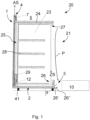
- the Figure 1 is schematically shown as an example. Shown in a side view is a refrigerated cabinet 20 in the form of a cabinet standing on feet 41 on the floor with an open removal side 21 facing the customer.
- the refrigerated cabinet 20 comprises a housing 24 with an internal cooling chamber 23, which is divided into several shelf units 28 for the presentation of products to be cooled. Between the housing 24 and the cooling chamber 23, the circulation channel 25 runs over three of the four sides, in which the fan 12 for generating the circulation flow ZS and the heat exchanger 29 are arranged.
- the circulation flow ZS flows from the outlet 27 directed vertically downwards to the inlet 26 directed vertically upwards over the removal side 21 and thus the entire cooling chamber 23.
- the arrow P shows that cold is transferred to the surrounding air by the circulation flow ZS, but also from the cooling chamber 23 as a result of a temperature gradient. is discharged on the removal side and flows outwards towards the area 10 close to the floor in front of the refrigerated cabinet 20.
- the suction device 1 is arranged integrally on the refrigerated cabinet 20 with the suction channel 2 extending continuously from the suction opening 3 on the removal side 21 to the blow-out opening 4 provided in the upper area 5 of the refrigerated cabinet, the inner wall of the suction channel 2 being formed by the housing 24.
- the suction opening 3 of the suction channel 2 is directly adjacent to the inlet 26 in the circulation channel 25 and has a central orientation which runs at an angle ⁇ of 45° to a vertical.
- the inlet 26 and the suction opening 3 are spaced or separated by the separating device 26'.
- the suction opening 3 is formed by the separating device 26' and the inlet lip 26" which runs at an angle to the removal side 21.
- the inlet lip 26" has an inlet slope directed into the suction channel 2.
- the opening width of the intake opening is approximately 80°.
- the fan 7 for generating the extraction flow AS is arranged on the extraction channel 2 in the rear, i.e. opposite the removal side 21, top area 5 of the refrigerated cabinet and forms the blow-out opening 4 of the extraction channel 2.
- the extraction flow AS is generated by the fan 7, which sucks in both cooled air (arrow P) emerging from the cooling chamber 23 and air located in the area 10 near the floor and blows it out via the blow-out opening 4.
- the extraction channel 2 runs on the floor and rear parallel to the circulation channel 25 and past the waste heat-generating components of the refrigerated cabinet 20, shown here only by the heat exchanger 29.
- cooling grids can also be flowed over or around, for example.
- the construction can also be designed as an attachment to existing refrigerated cabinets.
- a temperature sensor and a control for volume flow control of the fan 7 are used depending on a temperature value, in particular the temperature value of the extraction flow AS.
- the control can be integrated into the control of the volume flow of the fan 12 of the refrigeration unit 20, so that the two volume flows of the extraction flow AS and the circulation flow ZS are controlled dependently on each other.
- the volume flow of the extraction flow AS conveyed by the fan 7 is smaller than the volume flow of the circulation flow ZS conveyed by the blower 12, so that the extraction flow AS does not negatively influence the circulation flow ZS.
- the volume flow of the extraction flow AS can also be temporarily larger than that of the circulation flow ZS, for example if a significant cooling of the extraction flow AS is detected and it can therefore be concluded that there is an accumulation of cooled air in the area 10 near the floor in front of the refrigerated cabinet 10.
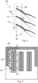
- FIGS 2 - 4 show a schematic representation of a ventilation device 100 on a refrigeration unit 20, which can be designed in the form of the refrigeration unit 20 from Figure 1.
- the ventilation device 100 for the embodiment according to Figure 1 The features described are applicable to the refrigerated cabinet in accordance with Figures 2 to 4 transferable, even if the details are not presented again.
- the ventilation device 100 is arranged on the top of the refrigerated cabinet 20 and, in the embodiment shown, comprises three fans 7 designed as radial fans, which are arranged along the length of the refrigerated cabinet 20 at the same distance from each other.
- a separating element designed in the form of a separating strip 59 extends over the entire length of the refrigerated cabinet 20 and forms three sections 59', 59", 59′′′ that are angled towards each other, with the fans 7 being attached to their blowers in the middle section 59".
- the separating strip can alternatively be divided into segments, each with a fan.
- the fans 7 suck air from the refrigerated cabinet top area 5 from the zone behind the separating strip 59 and blow it diagonally upwards through openings in the separating strip 59 into a zone in front of the refrigerated cabinet 20 on the removal side 21.
- the flow 99 generated by the fans 7 is in Figure 2 shown spatially.
- the middle section 59" of the separating strip 59 is extended at the same angle to the vertical angle, so that the blowing direction over the separating strip 59.
- the double-angled outflow in the direction of the ceiling and along the length of the refrigerated cabinet promotes the exchange of air in front of the refrigerated cabinet 20 and reduces the formation of cold air accumulations in front of the refrigerated cabinet 20.
- Exhaust ducts 73 are arranged on each of the fans 7, which increase the throw distance and determine the throw direction. In the embodiment shown, the exhaust ducts 73 are inserted through openings or into openings in the separating strip 59.
- the Figures 2-4 The ventilation device 100 shown is in one embodiment mounted on the top area 5 of the refrigerated cabinet 20 made of Figure 1 positioned so that the fans 7 suck in air from the extraction duct 2.
- Figure 5 shows a schematic arrangement of the refrigeration units 20 to freezers or refrigerators 81, for example in a supermarket, wherein the outflow direction S of the fans 7 of the ventilation device 100 is directed anti-clockwise, since the main direction of movement of the customers along the refrigeration units 20 is set or expected in this way.
- the fans 7 generate a vortex W around the freezers or refrigerators 81, which prevents or reduces the accumulation of cold air in front of the refrigeration units 20.
- the horizontal angle is aligned accordingly in the other direction and is in a range of preferably -35° ⁇ -50°.
Landscapes
- Physics & Mathematics (AREA)
- Thermal Sciences (AREA)
- Cold Air Circulating Systems And Constructional Details In Refrigerators (AREA)
Description
- Die Erfindung betrifft ein Kühlmöbel zur Verringerung einer Ansammlung von aus dem Kühlmöbel ausströmender gekühlter Luft in einem bodennahen Bereich vor dem Kühlmöbel sowie ein zugehöriges Kühlmöbel.
- Kühlmöbel werden beispielsweise in Supermärkten eingesetzt, um gekühlte oder gefrorene Produkte anzubieten. Insbesondere gekühlte Produkte werden bevorzugt über eine offene, d.h. nicht durch eine Tür oder dergleichen abdeckbare Entnahmeseite präsentiert und von den Kunden entnommen. Dabei tritt über die offene, auf den Kunden ausgerichtete Entnahmeseite ständig ein Teil der gekühlten Luft aus dem Kühlmöbel aus und sammelt sich im bodennahen Bereich vor dem Kühlmöbel. Diesbezüglich ist negativ, dass die Kunden genau in diesem Bereich stehen, während sie ihre Auswahl der zu entnehmenden Produkte treffen. Die Ansammlung kalter Luft an den Füßen und Beinen wird als unangenehm empfunden und verkürzt die Verweildauer an dem Kühlmöbel, wodurch der erzielbare Umsatz des Kühlmöbelbetreibers eingeschränkt wird.
- Zur Verringerung der Ansammlung gekühlter Luft im bodennahen Bereich vor der Entnahmeseite werden teilweise die Luftströmung beeinflussende Leitbleche, beispielsweise an den Regalböden der Kühlmöbel eingesetzt, die jedoch nur einen geringen positiven Einfluss bieten. Die Entnahmeseite durch Türen zu verschließen ist eine alternative Variante, die jedoch von den Kühlmöbelbetreibern und auch von vielen Kunden nicht als praktisch empfunden wird.
- Druckschriftlicher Stand der Technik aus dem vorliegenden technischen Gebiet ist beispielsweise aus den Dokumenten
DE 20 2018 102 902 U ,US 2017/150829 A1 undFR 2 160 771 A1 - Der Erfindung liegt deshalb die Aufgabe zugrunde, eine Vorrichtung bereit zu stellen, mit der eine Ansammlung gekühlter Luft im bodennahen Bereich vor Kühlmöbeln mit zum Kunden gerichteter offener Entnahmeseite deutlich reduziert werden kann.
- Diese Aufgabe wird durch die Merkmalskombination gemäß Patentanspruch 1 gelöst.
- Erfindungsgemäß wird ein Kühlmöbel vorgeschlagen, umfassend ein Gehäuse, eine Kühlkammer zur Aufnahme von zu Kühlendem mit einer offenen Entnahmeseite, einen zwischen dem Gehäuse und der Kühlkammer durchgehend verlaufenden Zirkulationskanal, in dem das Gebläse angeordnet ist, das ausgebildet ist, die Zirkulationsströmung um die Kühlkammer und über die offene Entnahmeseite hinweg zu erzeugen. Der Zirkulationskanal weist auf der Entnahmeseite einen Einlass und einen Auslass auf, die aufeinander zuweisend ausgerichtet sind, wobei an dem Kühlmöbel eine Ventilationsvorrichtung für das zumindest auf einer Entnahmeseite offenes oder über eine Tür zu öffnendes Kühlmöbel zur Verringerung einer Ansammlung von aus dem Kühlmöbel ausströmender gekühlter Luft in einem bodennahen Bereich vor dem Kühlmöbel auf dessen offener Entnahmeseite angeordnet ist. Die Ventilationsvorrichtung umfasst mindestens einem Ventilator, der vorzugsweise in einen dem bodennahen Bereich gegenüberliegenden Kühlmöbeloberseitenbereich angeordnet ist. Der mindestens eine Ventilator ist ausgebildet und ausgerichtet, Luft aus dem Kühlmöbeloberseitenbereich oder dem bodennahen Bereich anzusaugen und in einer mittleren Ausblasrichtung in einem Horizontalwinkel ϕ gegenüber einer zur Entnahmeseite parallelen Vorderebene entlang des Kühlmöbels sowie in einem Vertikalwinkel β gegenüber einer zur Kühlmöbeloberseite parallelen und zur Vorderebene senkrechten Topebene auszublasen. Der Winkelbereich für den Horizontalwinkel liegt zwischen 20° und 70° bzw. zwischen -20 und - 70°, je nachdem in welche Richtung relativ zu dem Kühlmöbel ausgeblasen wird. Der Winkelbereich für den Vertikalwinkel liegt zwischen 20° und 70°, wobei die Ausblasrichtung stets nach oben in eine Richtung weg von dem bodennahen Bereich erfolgt.
- Über den mindestens einen Ventilator im Kühlmöbeloberseitenbereich wird ein Strömungswirbel um das Kühlmöbel insbesondere auch im bodennahen Bereich vor der Entnahmeseite des Kühlmöbels erzeugt, welcher die Ansammlung von aus dem Kühlmöbel entweichender kalter Luft reduziert. Besonders vorteilhaft ist der Effekt, wenn für die Winkel ϕ und β gilt: 35°≤ϕ,β≤50° oder alternativ -35°≥ϕ≥-50° und 35°≤β≤50°. Häufig sind von den offenen Kühlmöbeln topbeladene Gefriertruhen oder Kühltruhen positioniert, so dass die von dem mindestens einen Ventilator erzeugte Strömung einen Wirbel oder eine Zirkulationsströmung um die Gefriertruhe oder Kühltruhe erzeugt, welche gleichzeitig die Kaltluft vor dem Kühlmöbel beseitigt.
- Der Horizontalwinkel ϕ ist deshalb mit positiven und negativen Winkelbereichen angegeben, weil sich die Ausrichtung danach richtet, in welcher Hauptbewegungsrichtung sich Kunden entlang des Kühlmöbels bewegen, z. B. im Uhrzeigersinn oder gegen den Uhrzeigersinn. Die Ausrichtung erfolgt derart, dass die Ausblasrichtung in der Bewegungsrichtung erfolgt, so dass der Kunde keine Strömung von vorne oder schräg vorne verspürt.
- Zur Erhöhung der Wurfweite und zur winkelgetreuen Erzielung der Ausblasrichtung sieht eine Variante der Ventilationsvorrichtung vor, dass der mindestens eine Ventilator einen Ausblaskanal aufweist, der in den Ventilator integriert oder daran angeschlossen ist.
- In einer günstigen Ausführungsvariante umfasst die Ventilationsvorrichtung ferner ein Trennelement, welches einen Ansaugbereich und einen Ausblasbereich des Ventilators strömungstechnisch abgrenzt. Der mindestens eine Ventilator saugt aus dem Ansaugbereich Luft an und bläst diese auf der Entnahmeseite des Kühlmöbels aus. Das Trennelement dient zum einen als Abtrennung für die Strömung des mindestens einen Ventilators, zum anderen als Sichtschutz, da der mindestens eine Ventilator rückseitig des Trennelements im rückwärtigen Bereich des Kühlmöbels positioniert ist.
- Vorteilhafterweise wird vorgesehen, dass das Trennelement ausgebildet ist, sich über eine gesamte Länge einer Öffnungsbreite der Entnahmeseite des Kühlmöbels zu erstrecken. In anderen Worten erstreckt sich das Trennelement über die gesamte Länge des Kühlmöbels, wenn seine Abmessungen definiert sind als Länge, Tiefe von der Entnahmeseite bis zur Rückseite und vertikale Höhe.
- Die Ventilationsvorrichtung sieht in einer Weiterbildung vor, dass der mindestens eine Ventilator an dem Trennelement befestigt gehalten ist. Das Trennelement übernimmt dann die weitere Aufgabe, als Befestigungsvorrichtung für den mindestens einen Ventilator zu dienen und kann als Baueinheit vormontiert und an das Kühlmöbel angebracht werden.
- Ferner weist das Trennelement in einer günstigen Ausführung mehrere zueinander gewinkelt verlaufende Abschnitte auf. Der mindestens eine Ventilator wird vorzugsweise an einem der Abschnitte befestigt, wobei dieser Abschnitt den Vertikalwinkel β bestimmt. Die Ausrichtung der Ausblasrichtung im Vertikalwinkel β wird somit in einfacher Weise über den Abschnitt des Trennelements festgelegt.
- Soweit vorstehend von mindestens einem Ventilator die Rede war, so ist bei der Ventilationsvorrichtung vorzugsweise vorgesehen, dass mehrere Ventilatoren in einer Reihe angeordnet und jeweils identisch ausgerichtet sind, um jeweils in demselben Horizontalwinkel und Vertikalwinkel auszublasen. Die dadurch erzielte Wirkung zur Lösung der Aufgabe ist noch verbessert. Zudem kann die Drehzahl jedes einzelnen Ventilators reduziert werden, um die Geräuscherzeugung zu begrenzen.
- In einer bevorzugten Ausführung der Ventilationsvorrichtung sind die Ventilatoren als Radialventilatoren ausgebildet.
- In Ergänzung der vorstehend beschriebenen Ventilationsvorrichtung ist erfindungsgemäß zudem eine Absaugvorrichtung vorgesehen werden. Hierzu wird eine Absaugvorrichtung für das zumindest auf der Entnahmeseite offenes Kühlmöbel zur Verringerung einer Ansammlung von aus dem Kühlmöbel ausströmender gekühlter Luft in einem bodennahen Bereich vor dem Kühlmöbel auf dessen offener Entnahmeseite vorgeschlagen, mit einem durchgängigen Absaugkanal und mindestens einem an dem Absaugkanal angeordneten Ventilator der Ventilationsvorrichtung zur Erzeugung einer Absaugströmung.
- Erfindungsgemäß weist der Absaugkanal eine Ansaugöffnung und eine Ausblasöffnung auf. Es können auch mehrere Absaugkanäle vorgesehen werden. Die Ansaugöffnung wird dabei in Richtung des bodennahen Bereichs vor dem Kühlmöbel, die Ausblasöffnung in einen dem bodennahen Bereich gegenüberliegenden Kühlmöbeloberseitenbereich ausgerichtet, so dass die aus dem Kühlmöbel ausströmende gekühlte Luft aus dem bodennahen Bereich absaugbar und auf dem Kühlmöbeloberseitenbereich ausblasbar ist.
- Die Absaugvorrichtung erzeugt über den oder die Ventilatoren der Ventilationsvorrichtung die Absaugströmung und saugt die aus dem Kühlmöbel austretende Luft ab, bevor sie sich im bodennahen Bereich räumlich vor dem Kühlmöbel als eine Art "Kaltluftsee" sammelt, in dem die Kunden stehen müssten. Ausgeblasen wird die Absaugströmung im Kühlmöbeloberseitenbereich durch die Ventilationsvorrichtung wie vorstehend beschrieben.
- In einer vorteilhaften Weiterbildung ist die Absaugvorrichtung in das Kühlmöbel integrierbar bzw. an dem Kühlmöbel anordenbar, insbesondere ist eine Ausführung bevorzugt, bei der der Absaugkanal teilweise durch das Kühlmöbel ausgebildet ist. Die Kühlmöbel umfassen ein die Kühlkammer bis auf die offene Entnahmeseite umschließendes Gehäuse. Der Absaugkanal wird vorzugsweise entlang diesem Gehäuse verbaut, so dass die Absaugströmung außenseitig entlang der Bodenseite und Rückwandseite des Gehäuses um das Kühlmöbel geführt wird. Die Ansaugöffnung des Absaugkanals weist vorzugsweise zur offenen Entnahmeseite und in Richtung des bodennahen Bereichs vor dem Kühlmöbel.
- Bei autark arbeitenden Kühlmöbeln sind auf der rückwärtigen Seite des Kühlmöbels die abwärmeerzeugenden Bauteile des thermischen Kreisprozesses angeordnet. Vorteilhaft ist eine Ausgestaltung der Absaugvorrichtung, bei der der Absaugkanal entlang der abwärmeerzeugenden Bauteile geführt wird, so dass die durch gekühlte Luft gekennzeichnete Absaugströmung an den abwärmeerzeugenden Bauteile vorbeigeführt und mithin der Wirkungsgrad des Kühlmöbels verbessert werden kann.
- Die Ansaugung über die Ansaugöffnung des Absaugkanals wird positiv beeinflusst, wenn ihre mittlere Ausrichtung gegenüber einer vertikalen Höhenrichtung des Kühlmöbels in einem Winkel von 20-60°, insbesondere 25-45° verläuft. Somit kann die von der offenen Entnahmeseite ausfallende Kaltluftströmung unmittelbar abgesaugt werden, bevor sie sich im bodennahen Bereich vor dem Kühlmöbel sammelt. Die spezielle Ausrichtung fördert die Zuführung der Kaltluftströmung in den Absaugkanal und gewährleistet gleichzeitig, dass permanent auch Luft aus dem bodennahen Bereich mit angesaugt wird, so dass gegebenenfalls durch äußere Einflüsse, beispielsweise bei der Befüllung des Kühlmöbels entstandene Ansammlungen von kalter Luft vor dem Kühlmöbel mit aufgelöst werden können.
- Die Absaugvorrichtung umfasst in einer Weiterbildung ferner eine Steuerung und einen Temperatursensor. Der Temperatursensor wird vorzugsweise am oder im Absaugkanal platziert, um die Temperatur der Absaugströmung zu messen. Die von dem Ventilator geförderte Absaugströmung ist über die Steuerung in Abhängigkeit von einem gemessenen Temperaturwert der Absaugströmung und mithin der Luft im bodennahen Bereich vor dem Kühlmöbel einstellbar.
- Die Erfindung umfasst zudem das Verfahren zur Verringerung der Ansammlung von aus einem Kühlmöbel ausströmender gekühlter Luft im bodennahen Bereich vor dem Kühlmöbel auf dessen offener Entnahmeseite, wobei mittels der Absaugvorrichtung die Absaugströmung erzeugt wird, über die aus dem Kühlmöbel ausströmende gekühlte Luft aus dem bodennahen Bereich abgesaugt und auf dem Kühlmöbeloberseitenbereich von der Ventilationsvorrichtung ausgeblasen wird.
- Bei den Kühlmöbeln mit offener Entnahmeseite wird über ein Gebläse eine Zirkulationsströmung entlang der zu den Kunden ausgerichteten Entnahmeseite und um das die Kühlkammer bestimmende Gehäuse des Kühlmöbels erzeugt. Die Zirkulationsströmung kann durch einen Wärmetauscher geführt werden und als Kühlluft für die Kühlkammern dienen. Nachdem das Gebläse jedoch immer nur einen bestimmten Volumenstrom fördern kann und es im Bereich der offenen Entnahmeseite auch zu Luftaustausch mit Umgebungsluft kommt, tritt stets eine gewisse Menge an gekühlter Luft aus dem Kühlmöbel aus und würde sich ohne das Verfahren vor dem Kühlmöbel sammeln. Bei dem Verfahren wird ferner vorzugsweise vorgesehen, dass die Absaugströmung zumindest abschnittsweise parallel zu der über das Gebläse erzeugten Zirkulationsströmung des Kühlmöbels verläuft.
- In einer Ausführung des Verfahrens wird vorgesehen, dass der Absaugkanal entlang abwärmeerzeugenden Bauteilen des thermischen Kreisprozesses des Kühlmöbels geführt wird und die Absaugströmung entlang der abwärmeerzeugenden Bauteile strömt oder die abwärmeerzeugenden Bauteile überströmt.
- Ferner ist das Verfahren dadurch gekennzeichnet, dass die Absaugströmung bezüglich ihres Volumenstroms über die Steuerung und einen Temperaturwert geregelt wird, der durch den im oder an dem Absaugkanal angeordneten Temperatursensor geliefert wird.
- In einer günstigen Ausgestaltung des Verfahrens ist vorgesehen, dass der von dem Ventilator geförderter Volumenstrom der Absaugströmung kleiner oder gleich dem von dem Gebläse geförderter Volumenstrom der Zirkulationsströmung ist. Somit wirkt die Absaugströmung hauptsächlich auf den bodennahen Bereich vor dem Kühlmöbel, ohne die Zirkulationsströmung negativ zu beeinflussen.
- Bei dem Kühlmöbel ist in einer Ausführung vorgesehen, dass die Ansaugöffnung des Absaugkanals und der Einlass des Zirkulationskanals unmittelbar aneinander angrenzen, wobei die Ansaugöffnung des Absaugkanals in den bodennahen Bereich vor dem Kühlmöbel und der Einlass des Zirkulationskanals in Richtung der offenen Entnahmeseite des Kühlmöbels ausgerichtet sind.
- Andere vorteilhafte Weiterbildungen der Erfindung sind in den Unteransprüchen gekennzeichnet bzw. werden nachstehend zusammen mit der Beschreibung einer Ausführung der Erfindung anhand der Figur näher dargestellt. Es zeigt:
- Fig. 1
- eine schematische Darstellung einer Seitenansicht einer Absaugvorrichtung an einem Kühlmöbel;
- Fig. 2
- eine perspektivische Rückansicht eines Kühlmöbels mit Ventilationsvorrichtung;
- Fig. 3
- eine schematische Darstellung einer Seitenansicht des Kühlmöbels mit Ventilationsvorrichtung aus
Figur 2 ; - Fig. 4
- eine schematische Darstellung einer Draufsicht einer Anordnung von Kühlmöbeln.
- Die
Figur 1 ist beispielhaft schematisch. Dargestellt ist in einer Seitenansicht ein Kühlmöbel 20 in Form eines auf Füßen 41 auf dem Boden stehenden Schrankes mit einer offenen, zum Kunden gerichteten Entnahmeseite 21. Das Kühlmöbel 20 umfasst ein Gehäuse 24 mit innen liegender Kühlkammer 23, die über mehrere Regaleinheiten 28 zur Präsentation von zu kühlenden Produkten unterteilt ist. Zwischen dem Gehäuse 24 und der Kühlkammer 23 verläuft über drei der vier Seiten der Zirkulationskanal 25, in dem das Gebläse 12 zur Erzeugung der Zirkulationsströmung ZS und der Wärmetauscher 29 angeordnet sind. - Die Zirkulationsströmung ZS überströmt von dem nach vertikal unten gerichteten Auslass 27 zu dem nach vertikal oben gerichteten Einlass 26 die Entnahmeseite 21 und mithin die gesamte Kühlkammer 23. Über den Pfeil P ist dargestellt, dass von der Zirkulationsströmung ZS, aber auch sonst aus der Kühlkammer 23 infolge eines Temperaturgradienten Kälte an die umgebende Luft entnahmeseitig abgegeben wird und nach außen in Richtung des bodennahen Bereichs 10 vor dem Kühlmöbel 20 strömt.
- An dem Kühlmöbel 20 ist integral die Absaugvorrichtung 1 mit dem sich von der Ansaugöffnung 3 auf der Entnahmeseite 21 zur im Kühlmöbeloberseitenbereich 5 vorgesehenen Ausblasöffnung 4 durchgängig erstreckenden Absaugkanal 2 angeordnet, wobei die Innenwand des Absaugkanals 2 durch das Gehäuse 24 gebildet wird. Die Ansaugöffnung 3 des Absaugkanals 2 grenzt unmittelbar an den Einlass 26 in den Zirkulationskanal 25 an und weist eine mittlere Ausrichtung auf, die gegenüber einer Vertikalen in einem Winkel α von 45° verläuft. Der Einlass 26 und die Ansaugöffnung 3 sind durch die Trenneinrichtung 26' beabstandet bzw. getrennt. Die Ansaugöffnung 3 wird über die Trenneinrichtung 26' und die zur Entnahmeseite 21 geneigt verlaufenden Einlauflippe 26" gebildet. Die Einlauflippe 26" weist hierzu eine in den Absaugkanal 2 hinein gerichtete Einlaufschräge auf. Die Öffnungsweite der Ansaugöffnung beträgt in etwa 80°. An dem Absaugkanal 2 ist im rückwärtigen, d.h. der Entnahmeseite 21 gegenüberliegenden, Kühlmöbeloberseitenbereich 5 der Ventilator 7 zur Erzeugung der Absaugströmung AS angeordnet und bildet die Ausblasöffnung 4 des Absaugkanals 2. Über den Ventilator 7 wird die Absaugströmung AS erzeugt, welcher sowohl aus der Kühlkammer 23 austretende gekühlte Luft (Pfeil P) als auch im bodennahen Bereich 10 befindliche Luft ansaugt und über die Ausblasöffnung 4 ausbläst. Der Absaugkanal 2 verläuft dabei bodenseitig sowie rückseitig parallel zur Zirkulationskanal 25 und vorbei an den abwärmeerzeugenden Bauteilen des Kühlmöbels 20, hier nur durch den Wärmetauscher 29 dargestellt. Zusätzlich können beispielsweise auch noch Kühlgitter überströmt oder umströmt werden. Alternativ kann die Konstruktion auch als Aufsatz an bestehende Kühlmöbel ausgebildet werden.
- Ebenfalls nicht explizit gezeigt, gleichwohl mit umfasst ist die Ausführung, dass ein Temperatursensor und eine Steuerung zur Volumenstromregelung des Ventilators 7 in Abhängigkeit eines Temperaturwerts, insbesondere des Temperaturwerts der Absaugströmung AS, eingesetzt werden. Die Steuerung kann hierbei in die Steuerung des Volumenstromes des Gebläses 12 des Kühlmöbels 20 integriert sein, so dass die beiden Volumenströme der Absaugströmung AS und der Zirkulationsströmung ZS zueinander abhängig geregelt werden. In der gezeigten Ausführung ist standardmäßig der von dem Ventilator 7 geförderte Volumenstrom der Absaugströmung AS kleiner als der von dem Gebläse 12 geförderte Volumenstrom der Zirkulationsströmung ZS, so dass die Absaugströmung AS die Zirkulationsströmung ZS nicht negativ beeinflusst. Jedoch kann der Volumenstrom der Absaugströmung AS auch zeitweise größer sein als derjenige der Zirkulationsströmung ZS, wenn beispielsweise eine deutliche Abkühlung der Absaugströmung AS erkannt und mithin auf eine Ansammlung von gekühlter Luft im bodennahen Bereich 10 vor dem Kühlmöbel 10 geschlossen werden kann.
- Die
Figuren 2 - 4 zeigen eine schematische Darstellung einer Ventilationsvorrichtung 100 auf einem Kühlmöbel 20, das in Form des Kühlmöbels 20 aus Figur 1 ausgebildet sein kann. Die zur Ausführung gemäßFigur 1 beschriebenen Merkmale sind auf das Kühlmöbel gemäß derFiguren 2 bis 4 übertragbar, selbst wenn die Details hierzu nicht nochmals dargestellt sind. - Die Ventilationsvorrichtung 100 ist auf der Oberseite des Kühlmöbels 20 angeordnet und umfasst in der gezeigten Ausführung drei als Radialventilatoren ausgebildete Ventilatoren 7, die entlang der Länge des Kühlmöbels 20 in jeweils demselben Abstand zueinander angeordnet sind. Ein in Form einer Trennleiste 59 ausgebildetes Trennelement erstreckt sich über die gesamte Länge des Kühlmöbels 20 und bildet drei zueinander gewinkelte Abschnitte 59', 59", 59‴, wobei die Ventilatoren 7 im mittleren Abschnitt 59" mit ihrem Ausblas befestigt sind. Die Trennleiste kann alternativ in Segmente mit jeweils einem Ventilator unterteilt sein. Die Ventilatoren 7 saugen Luft aus dem Kühlmöbeloberseitenbereich 5 von der Zone hinter der Trennleiste 59 und blasen dies durch Öffnungen in der Trennleiste 59 nach schräg oben in einen Zone vor dem Kühlmöbei 20 auf der der Entnahmeseite 21. Die mittlere Ausblasrichtung erfolgt, wie in
Figur 3 zu erkennen, in einem Vertikalwinkel β=50° gegenüber einer zur Kühlmöbeloberseite parallelen und zur Vorderebene senkrechten Topebene 96 und, wie inFigur 4 zu erkennen, in einem Horizontalwinkel ϕ=45° gegenüber einer zur Entnahmeseite 21 parallelen Vorderebene 97 entlang des Kühlmöbels 20. Die von den Ventilatoren 7 erzeugte Strömung 99 ist inFigur 2 räumlich dargestellt. Der Mittelabschnitt 59" der Trennleiste 59 ist in demselben Winkel zum Vertikalwinkel ausgereichtet, so dass die Ausblasrichtung über die Trennleiste 59 festlegbar ist. Die zweifach gewinkelte Ausströmung in Deckenrichtung und entlang der Längenerstreckung des Kühlmöbels fördert den Luftaustausch auch vor dem Kühlmöbel 20 und verringert die Bildung kalter Luftansammlungen vor dem Kühlmöbel 20. - An den Ventilatoren 7 sind jeweils Ausblaskanäle 73 angeordnet, welche die Wurfweite vergrößern und die Wurfrichtung mitbestimmen. In der gezeigten Ausführung sind die Ausblaskanäle 73 durch Öffnungen bzw. in Öffnungen in der Trennleiste 59 gesteckt.
- Die in den
Figuren 2-4 gezeigte Ventilationsvorrichtung 100 wird in einer Ausführung auf den Kühlmöbeloberseitenbereich 5 des Kühlmöbels 20 ausFigur 1 positioniert, so dass die Ventilatoren 7 aus dem Absaugkanal 2 Luft ansaugen. -
Figur 5 zeigt eine schematische Anordnung der Kühlmöbel 20 zu Gefriertruhen oder Kühltruhen 81 beispielsweise in einem Supermarkt, wobei die Auströmrichtung S der Ventilatoren 7 der Ventilationsvorrichtung 100 gegen den Uhrzeigersinn gerichtet ist, da die Hauptbewegungsrichtung der Kunden entlang der Kühlmöbel 20 derart festgelegt oder erwartet ist. Die Ventilatoren 7 erzeugen einen Wirbel W um die Gefriertruhen oder Kühltruhen 81, welcher eine Ablagerung kalter Luft vor den Kühlmöbeln 20 verhindert oder reduziert. Wenn die Hauptbewegungsrichtung der das Kühlmöbel 20 nutzenden Personen entgegengesetzt verläuft, wird der Horizontalwinkel entsprechend in die andere Richtung ausgerichtet und liegt in einem Bereich von vorzugsweise -35°≥ϕ≥-50°.
Claims (13)
- Kühlmöbel (20) umfassend ein Gehäuse, eine Kühlkammer (23) zur Aufnahme von zu Kühlendem mit einer offenen Entnahmeseite (21), einen zwischen dem Gehäuse (24) und der Kühlkammer (23) durchgehend verlaufenden Zirkulationskanal (25), in dem ein Gebläse (12) angeordnet ist, das ausgebildet ist, eine Zirkulationsströmung (ZS) um die Kühlkammer (23) und über die offene Entnahmeseite (21) hinweg zu erzeugen, wobei der Zirkulationskanal (25) auf der Entnahmeseite (21) einen Einlass (26) und einen Auslass (27) aufweist, die aufeinander zuweisend ausgerichtet sind, wobei an dem Kühlmöbel (20) eine Ventilationsvorrichtung für das zumindest auf der Entnahmeseite (21) offene oder über eine Tür zu öffnende Kühlmöbel (20) zur Verringerung einer Ansammlung von aus dem Kühlmöbel (20) ausströmender gekühlter Luft in einem bodennahen Bereich (10) vor dem Kühlmöbel (20) auf dessen Entnahmeseite (21), mit mindestens einem Ventilator (7) angeordnet insbesondere in einen dem bodennahen Bereich (10) gegenüberliegenden Kühlmöbeloberseitenbereich (5) angeordnet ist, wobei der mindestens eine Ventilator (7) ausgebildet und ausgerichtet ist, Luft in einer mittleren Ausblasrichtung in einem Horizontalwinkel ϕ gegenüber einer zur Entnahmeseite (21) parallelen Vorderebene entlang des Kühlmöbels (20) sowie in einem Vertikalwinkel β gegenüber einer zur Kühlmöbeloberseite parallelen und zur Vorderebene senkrechten Topebene auszublasen, wobei für ϕ und β gilt 20°≤ϕ,β≤70° oder alternativ gilt -20°≥ϕ≥-70° und 20°≤β≤70°, wobei der mindestens eine Ventilator (7) mit mindestens einem Absaugkanal (2) zur Erzeugung einer Absaugströmung (AS) in Strömungsverbindung steht, wobei der wenigstens eine Absaugkanal (2) eine Ansaugöffnung (3) und eine Ausblasöffnung (4) aufweist, wobei die Ansaugöffnung (3) in Richtung des bodennahen Bereichs vor dem Kühlmöbel (20) und die Ausblasöffnung (4) in den Kühlmöbeloberseitenbereich (5) ausgerichtet oder ausrichtbar sind, so dass die aus dem Kühlmöbel (20) ausströmende gekühlte Luft aus dem bodennahen Bereich (10) absaugbar und über den mindestens einen Ventilator (7) ausblasbar ist.
- Kühlmöbel (20) nach Anspruch 1, dadurch gekennzeichnet, dass für ϕ und β gilt 35°≤ϕ,β≤50° oder alternativ gilt -35°≥ϕ≥-50° und 35°≤β≤50°.
- Kühlmöbel (20) nach Anspruch 1 oder 2, dadurch gekennzeichnet, dass der mindestens eine Ventilator (7) mindestens einen Ausblaskanal aufweist, der in den Ventilator (7) integriert oder daran angeschlossen ist und eine Wurfweite und Wurfrichtung des Ventilators bestimmt.
- Kühlmöbel (20) nach einem der vorigen Ansprüche, ferner umfassend ein Trennelement, welche insbesondere als Trennleiste (59) ausgebildet ist und einen Ansaugbereich und einen Ausblasbereich des Ventilators (7) strömungstechnisch abgrenzt, wobei der mindestens eine Ventilator (7) aus dem Ansaugbereich Luft ansaugt und diese auf der Entnahmeseite (21) des Kühlmöbels (20) ausbläst.
- Kühlmöbel (20) nach dem vorigen Anspruch, dadurch gekennzeichnet, dass das Trennelement ausgebildet ist, sich über eine gesamte Länge einer Öffnungsbreite der Entnahmeseite (21) des Kühlmöbels (20) zu erstrecken.
- Kühlmöbel (20) nach einem der vorigen Ansprüche 4 - 5, dadurch gekennzeichnet, dass der mindestens eine Ventilator (7) an dem Trennelement befestigt gehalten ist.
- Kühlmöbel (20) nach einem der vorigen Ansprüche 4 - 6, dadurch gekennzeichnet, dass das Trennelement mehrere zueinander gewinkelt verlaufende Abschnitte aufweist und der Vertikalwinkel β über einen der Abschnitte bestimmt ist.
- Kühlmöbel (20) nach einem der vorigen Ansprüche, dadurch gekennzeichnet, dass mehrere Ventilatoren (7) in einer Reihe angeordnet sind, die jeweils identisch ausgerichtet sind, um jeweils in demselben Horizontalwinkel und Vertikalwinkel auszublasen.
- Kühlmöbel (20) nach dem vorigen Anspruch, dadurch gekennzeichnet, dass die Ventilatoren als Radialventilatoren ausgebildet sind.
- Kühlmöbel (20) nach einem der vorigen Ansprüche, dadurch gekennzeichnet, dass der mindestens eine Absaugkanal (2) teilweise durch das Kühlmöbel (20) ausbildbar ist.
- Kühlmöbel (20) nach einem der vorigen Ansprüche, dadurch gekennzeichnet, dass die Ansaugöffnung (3) des Absaugkanals (2) eine mittlere Ausrichtung aufweist, die gegenüber einer vertikalen Höhenrichtung des Kühlmöbels (20) in einem Winkel (α) von 20 - 120°, insbesondere 25-75° verläuft.
- Kühlmöbel (20) nach einem der vorigen Ansprüche, dadurch gekennzeichnet, dass an der Ansaugöffnung (3) des Absaugkanals (2) eine Trenneinrichtung (26') und einer zur Entnahmeseite (21) geneigt verlaufenden Einlauflippe (26") mit einer Einlaufschräge ausgebildet ist, wobei die Trenneinrichtung (26') die Ansaugöffnung (3) gegenüber der Entnahmeseite (21) beabstandet.
- Kühlmöbel (20) nach einem der vorigen Ansprüche, dadurch gekennzeichnet, dass der Absaugkanal (2) entlang abwärmeerzeugenden Bauteilen des thermischen Kreisprozesses des Kühlmöbels (20) entlangführbar ist.
Applications Claiming Priority (1)
| Application Number | Priority Date | Filing Date | Title |
|---|---|---|---|
| DE102019117188.1A DE102019117188A1 (de) | 2019-06-26 | 2019-06-26 | Ventilationsvorrichtung für ein Kühlmöbel |
Publications (2)
| Publication Number | Publication Date |
|---|---|
| EP3756511A1 EP3756511A1 (de) | 2020-12-30 |
| EP3756511B1 true EP3756511B1 (de) | 2024-09-18 |
Family
ID=70616996
Family Applications (1)
| Application Number | Title | Priority Date | Filing Date |
|---|---|---|---|
| EP20173506.5A Active EP3756511B1 (de) | 2019-06-26 | 2020-05-07 | Kühlmöbel mit ventilationsvorrichtung |
Country Status (3)
| Country | Link |
|---|---|
| EP (1) | EP3756511B1 (de) |
| CN (1) | CN210663509U (de) |
| DE (1) | DE102019117188A1 (de) |
Families Citing this family (1)
| Publication number | Priority date | Publication date | Assignee | Title |
|---|---|---|---|---|
| CN112440672B (zh) * | 2020-12-10 | 2024-12-20 | 成都华日通讯技术股份有限公司 | 一种车载多级增压排风系统 |
Family Cites Families (6)
| Publication number | Priority date | Publication date | Assignee | Title |
|---|---|---|---|---|
| US3304736A (en) * | 1965-08-06 | 1967-02-21 | Emhart Corp | Refrigerated display case |
| FR2160771B1 (de) * | 1971-11-26 | 1976-04-30 | Mc Refrigeration | |
| JPH06241641A (ja) * | 1993-02-16 | 1994-09-02 | Fuji Electric Co Ltd | オープンショーケース |
| GB2422186B (en) * | 2004-12-06 | 2009-06-10 | Paul Scammell | Chilled product display and air supply system with free cooling |
| US10588429B2 (en) * | 2015-11-30 | 2020-03-17 | Hill Phoenix, Inc. | Refrigerated case with an induced airflow system |
| DE202018102902U1 (de) * | 2018-05-24 | 2018-05-30 | Ebm-Papst Mulfingen Gmbh & Co. Kg | Absaugvorrichtung für ein Kühlmöbel |
-
2019
- 2019-06-26 DE DE102019117188.1A patent/DE102019117188A1/de active Pending
- 2019-08-13 CN CN201921304617.7U patent/CN210663509U/zh not_active Expired - Fee Related
-
2020
- 2020-05-07 EP EP20173506.5A patent/EP3756511B1/de active Active
Also Published As
| Publication number | Publication date |
|---|---|
| DE102019117188A1 (de) | 2020-12-31 |
| CN210663509U (zh) | 2020-06-02 |
| EP3756511A1 (de) | 2020-12-30 |
Similar Documents
| Publication | Publication Date | Title |
|---|---|---|
| DE10143242A1 (de) | Kältegerät mit Kühlluftzirkulation | |
| DE4315538C1 (de) | Wärmeaustauscher, insbesondere Kühlgerät | |
| EP3756511B1 (de) | Kühlmöbel mit ventilationsvorrichtung | |
| EP0149157B1 (de) | Kühlmöbel | |
| DE202019103526U1 (de) | Ventilationsvorrichtung für ein Kühlmöbel | |
| DE102011006251A1 (de) | Kältegerät mit Lüfter | |
| EP1327112B1 (de) | Kühlgerät | |
| DE3307510A1 (de) | Gekuehlter schaukasten bzw. gekuehlte ausstellungstheke mit abtauung unter verwendung umgebender luft | |
| DE102017005226A1 (de) | Sockelkonzept | |
| DE202018102902U1 (de) | Absaugvorrichtung für ein Kühlmöbel | |
| EP1934541B1 (de) | Abstellplatte für ein kältegerät | |
| DE202008010063U1 (de) | Lufttechnische Einrichtung | |
| WO2019223916A1 (de) | Absaugvorrichtung für ein kühlmöbel | |
| DE102005021535A1 (de) | Kältegerät mit Umluftkühlung | |
| EP2637488B1 (de) | Klimagerät zur Kühlung von Elektronikgeräten oder Elektronikgeräteschränken mit Ausblasgitter | |
| DE2158147A1 (de) | Wandkühlschrank | |
| EP1242775B1 (de) | Kältegerät wie no-frost-kühl- oder gefrierschrank | |
| EP2691711B1 (de) | Kältegerät mit axiallüfter | |
| DE102010029578A1 (de) | Kältegerät mit innen liegendem Verdampfer | |
| EP2145139A2 (de) | Kühlgerät | |
| DE112005002832T5 (de) | Kühlvorrichtung | |
| DE19729794A1 (de) | Kühleinrichtung | |
| DE102017116395A1 (de) | Kühlmöbel | |
| DE8806275U1 (de) | Backofen | |
| EP2568238A2 (de) | Kühl- und/oder Gefriergerät |
Legal Events
| Date | Code | Title | Description |
|---|---|---|---|
| PUAI | Public reference made under article 153(3) epc to a published international application that has entered the european phase |
Free format text: ORIGINAL CODE: 0009012 |
|
| STAA | Information on the status of an ep patent application or granted ep patent |
Free format text: STATUS: THE APPLICATION HAS BEEN PUBLISHED |
|
| AK | Designated contracting states |
Kind code of ref document: A1 Designated state(s): AL AT BE BG CH CY CZ DE DK EE ES FI FR GB GR HR HU IE IS IT LI LT LU LV MC MK MT NL NO PL PT RO RS SE SI SK SM TR |
|
| AX | Request for extension of the european patent |
Extension state: BA ME |
|
| STAA | Information on the status of an ep patent application or granted ep patent |
Free format text: STATUS: REQUEST FOR EXAMINATION WAS MADE |
|
| 17P | Request for examination filed |
Effective date: 20210615 |
|
| RBV | Designated contracting states (corrected) |
Designated state(s): AL AT BE BG CH CY CZ DE DK EE ES FI FR GB GR HR HU IE IS IT LI LT LU LV MC MK MT NL NO PL PT RO RS SE SI SK SM TR |
|
| STAA | Information on the status of an ep patent application or granted ep patent |
Free format text: STATUS: EXAMINATION IS IN PROGRESS |
|
| 17Q | First examination report despatched |
Effective date: 20220919 |
|
| GRAP | Despatch of communication of intention to grant a patent |
Free format text: ORIGINAL CODE: EPIDOSNIGR1 |
|
| STAA | Information on the status of an ep patent application or granted ep patent |
Free format text: STATUS: GRANT OF PATENT IS INTENDED |
|
| INTG | Intention to grant announced |
Effective date: 20240502 |
|
| GRAS | Grant fee paid |
Free format text: ORIGINAL CODE: EPIDOSNIGR3 |
|
| GRAA | (expected) grant |
Free format text: ORIGINAL CODE: 0009210 |
|
| STAA | Information on the status of an ep patent application or granted ep patent |
Free format text: STATUS: THE PATENT HAS BEEN GRANTED |
|
| P01 | Opt-out of the competence of the unified patent court (upc) registered |
Free format text: CASE NUMBER: APP_42146/2024 Effective date: 20240717 |
|
| AK | Designated contracting states |
Kind code of ref document: B1 Designated state(s): AL AT BE BG CH CY CZ DE DK EE ES FI FR GB GR HR HU IE IS IT LI LT LU LV MC MK MT NL NO PL PT RO RS SE SI SK SM TR |
|
| REG | Reference to a national code |
Ref country code: GB Ref legal event code: FG4D Free format text: NOT ENGLISH |
|
| REG | Reference to a national code |
Ref country code: CH Ref legal event code: EP |
|
| REG | Reference to a national code |
Ref country code: DE Ref legal event code: R096 Ref document number: 502020009245 Country of ref document: DE |
|
| REG | Reference to a national code |
Ref country code: IE Ref legal event code: FG4D Free format text: LANGUAGE OF EP DOCUMENT: GERMAN |
|
| REG | Reference to a national code |
Ref country code: LT Ref legal event code: MG9D |
|
| PG25 | Lapsed in a contracting state [announced via postgrant information from national office to epo] |
Ref country code: NO Free format text: LAPSE BECAUSE OF FAILURE TO SUBMIT A TRANSLATION OF THE DESCRIPTION OR TO PAY THE FEE WITHIN THE PRESCRIBED TIME-LIMIT Effective date: 20241218 |
|
| PG25 | Lapsed in a contracting state [announced via postgrant information from national office to epo] |
Ref country code: GR Free format text: LAPSE BECAUSE OF FAILURE TO SUBMIT A TRANSLATION OF THE DESCRIPTION OR TO PAY THE FEE WITHIN THE PRESCRIBED TIME-LIMIT Effective date: 20241219 Ref country code: FI Free format text: LAPSE BECAUSE OF FAILURE TO SUBMIT A TRANSLATION OF THE DESCRIPTION OR TO PAY THE FEE WITHIN THE PRESCRIBED TIME-LIMIT Effective date: 20240918 |
|
| PG25 | Lapsed in a contracting state [announced via postgrant information from national office to epo] |
Ref country code: BG Free format text: LAPSE BECAUSE OF FAILURE TO SUBMIT A TRANSLATION OF THE DESCRIPTION OR TO PAY THE FEE WITHIN THE PRESCRIBED TIME-LIMIT Effective date: 20240918 |
|
| PG25 | Lapsed in a contracting state [announced via postgrant information from national office to epo] |
Ref country code: LV Free format text: LAPSE BECAUSE OF FAILURE TO SUBMIT A TRANSLATION OF THE DESCRIPTION OR TO PAY THE FEE WITHIN THE PRESCRIBED TIME-LIMIT Effective date: 20240918 |
|
| PG25 | Lapsed in a contracting state [announced via postgrant information from national office to epo] |
Ref country code: HR Free format text: LAPSE BECAUSE OF FAILURE TO SUBMIT A TRANSLATION OF THE DESCRIPTION OR TO PAY THE FEE WITHIN THE PRESCRIBED TIME-LIMIT Effective date: 20240918 |
|
| REG | Reference to a national code |
Ref country code: NL Ref legal event code: MP Effective date: 20240918 |
|
| PG25 | Lapsed in a contracting state [announced via postgrant information from national office to epo] |
Ref country code: RS Free format text: LAPSE BECAUSE OF FAILURE TO SUBMIT A TRANSLATION OF THE DESCRIPTION OR TO PAY THE FEE WITHIN THE PRESCRIBED TIME-LIMIT Effective date: 20241218 |
|
| PG25 | Lapsed in a contracting state [announced via postgrant information from national office to epo] |
Ref country code: RS Free format text: LAPSE BECAUSE OF FAILURE TO SUBMIT A TRANSLATION OF THE DESCRIPTION OR TO PAY THE FEE WITHIN THE PRESCRIBED TIME-LIMIT Effective date: 20241218 Ref country code: NO Free format text: LAPSE BECAUSE OF FAILURE TO SUBMIT A TRANSLATION OF THE DESCRIPTION OR TO PAY THE FEE WITHIN THE PRESCRIBED TIME-LIMIT Effective date: 20241218 Ref country code: LV Free format text: LAPSE BECAUSE OF FAILURE TO SUBMIT A TRANSLATION OF THE DESCRIPTION OR TO PAY THE FEE WITHIN THE PRESCRIBED TIME-LIMIT Effective date: 20240918 Ref country code: HR Free format text: LAPSE BECAUSE OF FAILURE TO SUBMIT A TRANSLATION OF THE DESCRIPTION OR TO PAY THE FEE WITHIN THE PRESCRIBED TIME-LIMIT Effective date: 20240918 Ref country code: GR Free format text: LAPSE BECAUSE OF FAILURE TO SUBMIT A TRANSLATION OF THE DESCRIPTION OR TO PAY THE FEE WITHIN THE PRESCRIBED TIME-LIMIT Effective date: 20241219 Ref country code: FI Free format text: LAPSE BECAUSE OF FAILURE TO SUBMIT A TRANSLATION OF THE DESCRIPTION OR TO PAY THE FEE WITHIN THE PRESCRIBED TIME-LIMIT Effective date: 20240918 Ref country code: BG Free format text: LAPSE BECAUSE OF FAILURE TO SUBMIT A TRANSLATION OF THE DESCRIPTION OR TO PAY THE FEE WITHIN THE PRESCRIBED TIME-LIMIT Effective date: 20240918 |
|
| PG25 | Lapsed in a contracting state [announced via postgrant information from national office to epo] |
Ref country code: NL Free format text: LAPSE BECAUSE OF FAILURE TO SUBMIT A TRANSLATION OF THE DESCRIPTION OR TO PAY THE FEE WITHIN THE PRESCRIBED TIME-LIMIT Effective date: 20240918 |
|
| PG25 | Lapsed in a contracting state [announced via postgrant information from national office to epo] |
Ref country code: PT Free format text: LAPSE BECAUSE OF FAILURE TO SUBMIT A TRANSLATION OF THE DESCRIPTION OR TO PAY THE FEE WITHIN THE PRESCRIBED TIME-LIMIT Effective date: 20250120 Ref country code: IS Free format text: LAPSE BECAUSE OF FAILURE TO SUBMIT A TRANSLATION OF THE DESCRIPTION OR TO PAY THE FEE WITHIN THE PRESCRIBED TIME-LIMIT Effective date: 20250118 |
|
| PG25 | Lapsed in a contracting state [announced via postgrant information from national office to epo] |
Ref country code: RO Free format text: LAPSE BECAUSE OF FAILURE TO SUBMIT A TRANSLATION OF THE DESCRIPTION OR TO PAY THE FEE WITHIN THE PRESCRIBED TIME-LIMIT Effective date: 20240918 Ref country code: SM Free format text: LAPSE BECAUSE OF FAILURE TO SUBMIT A TRANSLATION OF THE DESCRIPTION OR TO PAY THE FEE WITHIN THE PRESCRIBED TIME-LIMIT Effective date: 20240918 |
|
| PG25 | Lapsed in a contracting state [announced via postgrant information from national office to epo] |
Ref country code: ES Free format text: LAPSE BECAUSE OF FAILURE TO SUBMIT A TRANSLATION OF THE DESCRIPTION OR TO PAY THE FEE WITHIN THE PRESCRIBED TIME-LIMIT Effective date: 20240918 |
|
| PG25 | Lapsed in a contracting state [announced via postgrant information from national office to epo] |
Ref country code: EE Free format text: LAPSE BECAUSE OF FAILURE TO SUBMIT A TRANSLATION OF THE DESCRIPTION OR TO PAY THE FEE WITHIN THE PRESCRIBED TIME-LIMIT Effective date: 20240918 |
|
| PG25 | Lapsed in a contracting state [announced via postgrant information from national office to epo] |
Ref country code: PL Free format text: LAPSE BECAUSE OF FAILURE TO SUBMIT A TRANSLATION OF THE DESCRIPTION OR TO PAY THE FEE WITHIN THE PRESCRIBED TIME-LIMIT Effective date: 20240918 Ref country code: CZ Free format text: LAPSE BECAUSE OF FAILURE TO SUBMIT A TRANSLATION OF THE DESCRIPTION OR TO PAY THE FEE WITHIN THE PRESCRIBED TIME-LIMIT Effective date: 20240918 |
|
| PG25 | Lapsed in a contracting state [announced via postgrant information from national office to epo] |
Ref country code: SK Free format text: LAPSE BECAUSE OF FAILURE TO SUBMIT A TRANSLATION OF THE DESCRIPTION OR TO PAY THE FEE WITHIN THE PRESCRIBED TIME-LIMIT Effective date: 20240918 Ref country code: IT Free format text: LAPSE BECAUSE OF FAILURE TO SUBMIT A TRANSLATION OF THE DESCRIPTION OR TO PAY THE FEE WITHIN THE PRESCRIBED TIME-LIMIT Effective date: 20240918 |
|
| REG | Reference to a national code |
Ref country code: DE Ref legal event code: R097 Ref document number: 502020009245 Country of ref document: DE |
|
| PGFP | Annual fee paid to national office [announced via postgrant information from national office to epo] |
Ref country code: DE Payment date: 20250519 Year of fee payment: 6 |
|
| PG25 | Lapsed in a contracting state [announced via postgrant information from national office to epo] |
Ref country code: DK Free format text: LAPSE BECAUSE OF FAILURE TO SUBMIT A TRANSLATION OF THE DESCRIPTION OR TO PAY THE FEE WITHIN THE PRESCRIBED TIME-LIMIT Effective date: 20240918 |
|
| PLBE | No opposition filed within time limit |
Free format text: ORIGINAL CODE: 0009261 |
|
| STAA | Information on the status of an ep patent application or granted ep patent |
Free format text: STATUS: NO OPPOSITION FILED WITHIN TIME LIMIT |
|
| 26N | No opposition filed |
Effective date: 20250619 |
|
| PG25 | Lapsed in a contracting state [announced via postgrant information from national office to epo] |
Ref country code: SE Free format text: LAPSE BECAUSE OF FAILURE TO SUBMIT A TRANSLATION OF THE DESCRIPTION OR TO PAY THE FEE WITHIN THE PRESCRIBED TIME-LIMIT Effective date: 20240918 |
|
| REG | Reference to a national code |
Ref country code: CH Ref legal event code: H13 Free format text: ST27 STATUS EVENT CODE: U-0-0-H10-H13 (AS PROVIDED BY THE NATIONAL OFFICE) Effective date: 20251223 |
|
| PG25 | Lapsed in a contracting state [announced via postgrant information from national office to epo] |
Ref country code: LU Free format text: LAPSE BECAUSE OF NON-PAYMENT OF DUE FEES Effective date: 20250507 |
|
| PG25 | Lapsed in a contracting state [announced via postgrant information from national office to epo] |
Ref country code: CH Free format text: LAPSE BECAUSE OF NON-PAYMENT OF DUE FEES Effective date: 20250531 |
|
| GBPC | Gb: european patent ceased through non-payment of renewal fee |
Effective date: 20250507 |
|
| REG | Reference to a national code |
Ref country code: BE Ref legal event code: MM Effective date: 20250531 |
|
| PG25 | Lapsed in a contracting state [announced via postgrant information from national office to epo] |
Ref country code: MC Free format text: LAPSE BECAUSE OF FAILURE TO SUBMIT A TRANSLATION OF THE DESCRIPTION OR TO PAY THE FEE WITHIN THE PRESCRIBED TIME-LIMIT Effective date: 20240918 |
|
| PG25 | Lapsed in a contracting state [announced via postgrant information from national office to epo] |
Ref country code: GB Free format text: LAPSE BECAUSE OF NON-PAYMENT OF DUE FEES Effective date: 20250507 |
|
| PG25 | Lapsed in a contracting state [announced via postgrant information from national office to epo] |
Ref country code: IE Free format text: LAPSE BECAUSE OF NON-PAYMENT OF DUE FEES Effective date: 20250507 |
|
| PG25 | Lapsed in a contracting state [announced via postgrant information from national office to epo] |
Ref country code: BE Free format text: LAPSE BECAUSE OF NON-PAYMENT OF DUE FEES Effective date: 20250531 |
|
| PG25 | Lapsed in a contracting state [announced via postgrant information from national office to epo] |
Ref country code: FR Free format text: LAPSE BECAUSE OF NON-PAYMENT OF DUE FEES Effective date: 20250531 |