EP3755910B1 - Zusammenklappbarer griff für ein werkzeug - Google Patents
Zusammenklappbarer griff für ein werkzeug Download PDFInfo
- Publication number
- EP3755910B1 EP3755910B1 EP19754222.8A EP19754222A EP3755910B1 EP 3755910 B1 EP3755910 B1 EP 3755910B1 EP 19754222 A EP19754222 A EP 19754222A EP 3755910 B1 EP3755910 B1 EP 3755910B1
- Authority
- EP
- European Patent Office
- Prior art keywords
- handle
- toggle linkage
- coupler
- handle member
- tool
- Prior art date
- Legal status (The legal status is an assumption and is not a legal conclusion. Google has not performed a legal analysis and makes no representation as to the accuracy of the status listed.)
- Active
Links
Images











Classifications
-
- A—HUMAN NECESSITIES
- A46—BRUSHWARE
- A46B—BRUSHES
- A46B5/00—Brush bodies; Handles integral with brushware
- A46B5/002—Brush bodies; Handles integral with brushware having articulations, joints or flexible portions
- A46B5/0033—Brush bodies; Handles integral with brushware having articulations, joints or flexible portions bending or stretching or collapsing
- A46B5/0041—Mechanical joint or hinge, made up of several components
-
- A—HUMAN NECESSITIES
- A46—BRUSHWARE
- A46B—BRUSHES
- A46B5/00—Brush bodies; Handles integral with brushware
- A46B5/0095—Removable or interchangeable brush heads
-
- B—PERFORMING OPERATIONS; TRANSPORTING
- B25—HAND TOOLS; PORTABLE POWER-DRIVEN TOOLS; MANIPULATORS
- B25G—HANDLES FOR HAND IMPLEMENTS
- B25G1/00—Handle constructions
- B25G1/04—Handle constructions telescopic; extensible; sectional
-
- B—PERFORMING OPERATIONS; TRANSPORTING
- B25—HAND TOOLS; PORTABLE POWER-DRIVEN TOOLS; MANIPULATORS
- B25G—HANDLES FOR HAND IMPLEMENTS
- B25G3/00—Attaching handles to the implements
- B25G3/38—Hinged, pivoted, swivelling, or folding joints
-
- A—HUMAN NECESSITIES
- A46—BRUSHWARE
- A46B—BRUSHES
- A46B2200/00—Brushes characterized by their functions, uses or applications
- A46B2200/30—Brushes for cleaning or polishing
- A46B2200/302—Broom
Definitions
- the present invention generally relates to tools having long handles, such as without limitation implements such as brooms, mops, or others as some examples.
- Handles that slide into one another, or "telescope,” have been used to provide collapsibility for some implements, but they are not ideally suited for the application of axial forces such that which occurs when using a broom, mop, or other tool or implement.
- Such telescope handles generally tend to break prematurely or collapse unexpectedly when in use.
- these types of handles require some sections to have a smaller diameter than others, which unacceptably reduces strength and rigidity.
- Another problem with telescoping handles is that foreign particles or liquids can find their way into the telescoping portions and can interfere with proper operation to collapse or extend the handle.
- Still another problem is that the internal mechanism that permits the telescoping action can break, which renders the handle to about half the size it needs to be for comfortable operation.
- a tool with foldable tool handle provides a hinge mechanism comprising a double-jointed articulating hinged joint.
- the hinge mechanism generally comprises four active hinge components in one embodiment, which are configured to cooperate for creating a rigid and torque resistant coupling between pivotably connected first and second handle sections or members.
- the use of multiple springs or fasteners is not required, thereby providing a mechanical simple and reliable constructions without need for use of multiple springs or fasteners.
- the handle is changeable via operation of a toggle linkage which couples first and second handle members together between (i) an unfolded condition in which first and second handle members pivotably coupled together by the hinged joint are coaxially aligned with a longitudinal axis of the handle, and (ii) a folded condition in which the second handle member movable to a position laterally offset from the longitudinal axis in side-by-side relationship to the first handle member for compactly shipping or storing the tool.
- the tool may be a maintenance tool such as broom or mop. Other type tools may use the articulating joint.
- the hinge mechanism includes a multitude of different locking features and actions which collectively form a mechanically interlocked joint when the first handle member is coaxially aligned and coupled to the second handle member with the handle assembly in the straight operational unfolded configuration or condition.
- the multiple locking feature act in concert to form an axially rigid handle assembly which resists twisting and torsional forces acting about the joint around the longitudinal axis when the tool is in use.
- Such robust joints thus have many practical uses and applications, only one of which is described herein as an example.
- any reference to direction or orientation is merely intended for convenience of description and is not intended in any way to limit the scope of the present invention.
- Relative terms such as “lower,” “upper,” “horizontal,” “vertical,” “above,” “below,” “up,” “down,” “top” and “bottom” as well as derivative thereof (e.g., “horizontally,” “downwardly,” “upwardly,” etc.) should be construed to refer to the orientation as then described or as shown in the drawing under discussion. These relative terms are for convenience of description only and do not require that the apparatus be constructed or operated in a particular orientation.
- Tool 11 includes a collapsible and jointed elongated handle assembly 10 (or variously "handle" 10 for brevity) defining a proximal end 52 closest to a user, a distal end 22, and longitudinal axis LA extending therebetween.
- Distal end 22 is configured for mounting an implement 30 thereto, such as broom or other implement as further described herein.
- Distal end 22 of the tool handle 10 may rigidly coupled to implement 30 as shown, or alternatively rotatably/pivotably coupled to the implement in other embodiments.
- the collapsible handle 10 includes elongated lower handle member 20 and elongated upper handle member 50 pivotably and hingedly coupled together by a hinge mechanism 60 comprising an articulated joint 61.
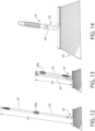
- the hinge mechanism 60 is configured so that the upper handle member 50 is rotatable at least 180 degrees relative to the lower handle member 20 to place the handle 10 in a collapsed folded configuration for shipment, storage, packaging, and/or display. This rotation is illustrated by a comparison for example of FIGS. 12 and 13 .
- the hinge mechanism 60 is configured such that the lower and upper handle members are not only pivotably coupled together, but the upper handle member 50 may be displaced to a position laterally offset and parallel to the lower handle member 20 in a stowed and collapsed folded configuration or condition, while concurrently still maintaining the physical coupling between the handle members as further described herein.
- Handle members 20, 50 may each have an elongated cylindrical body in one implementation. However, any suitable configuration and structure may be used. In one embodiment, as illustrated, handle members 20, 50 may each have hollow tubular construction for weight reduction. In other embodiments, portions of or the entire handle members may have a generally solid cross section. Handle members 20, 50 as depicted are cylindrical and have a circular transverse cross-sectional shape. In other embodiments, the handle members may have other configurations and solid or hollow cross-sectional shapes such as polygonal (e.g. hexagonal, octagonal, triangular, etc.), rectilinear (e.g. square or rectangular), a combination thereof, or other. Accordingly, the shape and structure of the handle members does not limit the invention.
- the hinge mechanism 60 comprises an upper hinge member such as coupler fitting 70 fixedly coupled to distal end 58 of the upper handle member 50 opposite its proximal end 52, and a lower hinge member such as coupler fitting 80 fixedly coupled to proximal end 28 of the lower handle member 20 opposite its distal end 22.
- Hinge coupler fittings 70, 80 each have a generally cylindrical body with various features formed therein as described below.
- the fittings each have a first mounting end 71,81 fixedly coupled to the ends of the upper and lower handle members 50, 20 at joint 61, and an opposite second coupling end 72, 82 configured for forming an interlocked arrangement between the fittings and toggle linkage 100 when the handle 10 is in the fully coupled and coaxially aligned operational configuration or condition.
- the mounting ends 71, 81 may have a cylindrical configuration of smaller diameter than the exposed main body of the fittings 70, 80.
- Mounting ends 71, 81 have a diameter slightly smaller diameter than the inside diameter of the open ends of handle members 20, 50 to which the coupler fittings 70, 80 are attached.
- the coupler fittings 70, 80 may be rigidly and fixedly coupled to the handle members 50, 20 at their mounting ends 71, 81 by any suitable means, such as for example without limitation fasteners, crimping, pins, welding, soldering, brazing, industrial adhesives, threaded coupling, interlock couplings, combinations thereof, or other methods.
- the coupling ends 72, 82 have a castellated configuration each comprising a plurality of lockable axial fingers or protrusions 110 that extend axially parallel to the longitudinal axis LA away from the ends of their respective handle members 50, 20.
- the locations of the axial protrusions 110 of the upper hinge coupler fitting 70 on upper handle 50 are the inverse of the locations of the axial protrusions 110 of the lower hinge coupler fitting 80 on lower handle member 20 so that they interlock when the handle 10 is placed in operational configuration, as further described herein.
- Each set of axially-extending protrusions 110 includes a spaced apart pair of first axial protrusions 110-1 on a first side of the coupler fittings 70, 80, and an axially-extending single second axial locking protrusion 110-2 on a second diametrically opposite side of the coupler fittings.
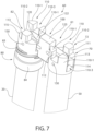
- the first axial protrusions 110-1 may be have the same shape, but may be oriented so that they are arranged as a mirror image of each other (see, e.g. FIG. 7 ).
- An axially (upwardly) and laterally inwards and outwards open locking receptacle 110-3 is defined between the pair of first axial protrusions 110-1 on coupler fitting 70.
- the second axial locking protrusions 110-2 are arranged diametrically opposite to the locking receptacle 110-3 on each coupler fitting.
- Receptacle 110-3 of coupler fitting insertably receives the single second axial locking protrusion 110-2 of the other coupler fitting 80 when the handle 10 is in the straight operational configuration or condition in which each handle member 20, 50 is coaxially aligned with the longitudinal axis.
- an axially and laterally open locking receptacle 110-3 is defined between the pair of first axial protrusions 110-1 on coupler fitting 80 which insertably receives the single axial locking protrusion 110-2 of the other coupler fitting 20 when the handle 10 is in the operational position.
- the mating sets of receptacles 110-3 and second locking protrusions 110-2 form a meshed and interlocked relationship to lock the coupler fittings 70, 80 together forming a rigid assemblage.
- the second axial locking protrusions 110-2 and their respective locking receptacles 110-3 preferably have a rectilinear complementary configuration in transverse cross-sectional shape.
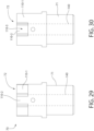
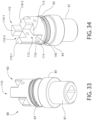
- FIGS. 25-40 shown the coupler fittings 70 and 80 in isolation and detail.
- the second axial locking protrusions 110-2 may have a three-dimensional substantially rectilinear configuration such as a rectangular cuboid (i.e. right rectangular prism) or square cuboid (right square prism).
- the term "substantially” connotes that some or all of the corners of the axial locking protrusions may be slightly chamfered or rounded to conform to the circular transverse cross-sectional shape of the coupler fittings and handle members, and to facilitate inserting the axial locking protrusions 110-2 into the locking receptacles 110-3.
- the second protrusions 110-2 and locking receptacles 110-3 thus each have a rectilinear cross-sectional shape (e.g. square or rectangular) which when interlocked, advantageously resists twisting of the coupler fittings 70, 80 (and their attached pole members 50, 20) about the longitudinal axis LA.
- the interlocked pairs of axial locking protrusions 110-2 and receptacles 110-3 define a first locking feature of the hinged joint 61.
- Axial locking protrusions 110-2 define a pair of planar bearing surfaces 111 facing in opposite directions on opposite sides of the axial locking protrusions. Bearing surfaces 111 abuttingly engage a mating pair of opposing planar bearing surfaces 112 formed on opposing sides of the locking receptacle 110-3.
- the interface between bearing surfaces 111 and 112 is one of flat-to-flat. Bearing surfaces 112 may be formed by inward facing sides of each first axial protrusion 110-1 (see also FIG. 7 ).
- the axial locking protrusions 110-2 and receptacles 110-3 are preferably dimensioned so that a snug frictional fit is formed therebetween when the axial locking protrusions are inserted into their respective receptacles. This enhances creation of a tight and rigid joint.
- the axially extending first axial protrusions 110-1 may have a substantially triangular prismatic shape.
- the term "substantially” connotes that some or all of the corners and outward facing side surface of the first axial protrusions may be slightly chamfered or rounded to conform to the circular transverse cross-sectional shape of the coupler fittings and handle members, and to facilitate inserting the axial locking protrusions 110-2 into the locking receptacles 110-3.
- the outward facing side surface of each first axial protrusion 110-1 may be arcuately convexly curved (see, e.g. FIGS. 7 , 8 , and 32 ).
- first axial protrusions 110-1 and second axial locking protrusions 110-2 may be used in other possible embodiments and does not limit the invention.
- a laterally extending elongated locking channel 113 is formed between the first axial protrusions 110-1 and second axial locking protrusion 110-2 of each coupler fitting 70, 80.
- Channel 113 extends below the axial protrusions 110-1, 110-2 towards the mounting ends 71, 81 of the coupler fittings 70, 80.
- Channel 113 extends laterally and diametrically from side-to-side of the coupler fittings, and perpendicularly intersects the longitudinal axis LA of the handle 10 at the centerline of the handle members 20, 50.
- Channel 113 is defined by two opposing and parallel sidewalls 116 which extend transversely across the coupler fittings 70, 80.
- the locking channel 113 further defines first lower and inboard planar surface 114 forming a bottom wall of the channel.
- Surface 114 is oriented perpendicularly to longitudinal axis LA.
- a second upper and outward planar surface 115 is defined by the coupler fittings 70. 80 at opposite sides of the fitting above the locking channel 113.
- Upper surface 115 is oriented parallel to lower surface 114 and perpendicularly to longitudinal axis LA.
- the axially extending protrusions 110 of each coupler fitting 70, 80 originate at upper surface 115 and extend upwards therefrom (see, e.g. FIGS. 7 and 8 ).
- Mounted channel 113 receives and lockingly engages an elongated toggle linkage 100 (further described herein) when the tool 11 is in the stowed configuration or condition (see, e.g. FIGS. 4 and 7 ). This helps maintain the tool in the folded condition.
- each coupler fitting 70, 80 comprising the foregoing features is formed as a monolithic unitary structure.
- the coupler fittings may be formed of a single injection molded polymeric body in one construction.
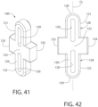
- toggle linkage 100 has an elongated rigid body comprising an elongated first arm portion 121 opposite an elongated second arm portion 122, and an elongated rectilinear block-shaped central or middle portion 123 formed therebetween.
- the arm portions 121, 122 may also be considered as extending in opposite directions from the block-shaped middle portion.
- a centerline CL is defined as extending between opposing ends 129 of the body; each end 129 being defined by one of the arm portions 121, 122.
- Toggle linkage 100 may thus be considered as having generally cruciform in overall configuration which is symmetrical about centerline CL.
- Middle portion 123 defines an integral opposing pair of locking block protrusions 124, 125 each of which project laterally outwards in opposite directions of the toggle linkage body from the centerline CL.
- the locking block protrusions 124, 125 may therefore extend outwards farther from centerline CL of toggle linkage 100 than the opposing lateral sides 128 of arm portions 121, 122 as shown.
- the block-shaped middle portion 1223 and each of its locking block protrusion 124, 125 has a generally rectangular or square cuboid configuration with a rectilinear transverse cross-sectional shape.
- a pair of elongated captive slots 120 are formed in toggle linkage 100.
- the slots 120 are oriented parallel to and intersect the centerline CL of the toggle linkage body.
- One slot 120 is formed in each arm portion 121, 122 of toggle linkage 100 on opposite sides of the block-shaped middle portion 123.
- Pivot pins 130 pass transversely through the hinge couplers 70, 80, and also pass through the slots 120 in toggle linkage 100 to translationally capture the linkage.
- the hinge couplers 70, 80 This enables the hinge couplers 70, 80 to be pulled far enough away from each other such that the axial protrusions 110 no longer interlock, thereby allowing the handle members 20, 50 and coupler fittings 70, 80 to be rotated relative to each other while still being connected via the linkage 100.
- the elongated slots 120 allow the handle members 20, 50 to assume a laterally offset and side-by-side relationship to each other (see, e.g. FIGS. 4 , 7 , and 13 ).
- slots 120 have closed ends and sides being completely contained with the confines the of toggle linkage body. Slots 120 therefore do not extend through the lateral sides 128 or ends 129 of the arm portions 121, 122. Each slot does however extend completely through opposing and parallel major front and rear surfaces 126, 127 of the toggle linkage 100 as shown. Pivot pins 130 that pass through the hinge couplers 70, 80, also pass through the linkage 100 and translationally capture the linkage 100 whereby the linkage 100 enables the hinge couplers 70, 80 to be pulled far enough away from each other that the fingers no longer interlock and the members can be rotated relative to each other while still being connected via the linkage 100.
- each handle member 20 and 50 is independently rotatable about their respective pivot pin in toggle linkage 100, and toggle linkage is rotatable about each pivot pin.
- the slot and pin arrangement allows the pin 130 to slide along the arm portions 121, 122 of toggle linkage 100 so that the handle members can be laterally displaced and translated relative to each.
- the present double-jointed hinge mechanism 60 contrasts to other folding long-handled tools having a single pivot which do not permit forming the laterally offset and side-by-side relationship between the upper and lower handle members 50, 20 shown for example in FIGS. 4 , 7 , and 13 .
- each coupler fitting 70, 80 includes an elongated central axial through passage 140 which extends along and coaxial with the longitudinal axis LA of the handle 10. Passages 140 pass completely through the mounting portions 71, 81 of the fittings at one end and penetrate through the body of the fitting to the open transverse channels 113 formed in the coupling ends 72, 82 of the fittings at the other end. The passages 140 are therefore in communication with the channels 113. Each passage may extend axially for about one-half or more of the length of the coupler fittings 70, 80 in certain embodiments, and are therefore distinguishable from simply short holes in an object.
- the arm portions 121, 122 of toggle linkage 100 are insertable into a respective one of the axial passages 140 when the handle 10 is in the straight operations configuration or condition. This forms an interlocked arrangement between the linkage 100 and walls of each of the passages 140 (see, e.g. FIG. 6 ).
- the central axial passages 140 and their respective arm portions preferably have a rectilinear complementary configuration in transverse cross-sectional shape.
- the cross-sectional shape of the arm portions 121, 122 and passages 140 may be rectangular or square in some embodiments.
- Each central axial passage 140 defines a plurality of inward facing planar bearing surfaces 141 (e.g. 2 pairs of orthogonal parallel surfaces) which engage the outer mating planar surfaces of each linkage arm portion 121, 122 defined by the pair of lateral sides 128 and major front and rear surfaces 126, 127 of the toggle linkage 100.
- the linkage arm portions 121, 122 slideably engage the bearing surfaces 141 when inserted into axial passages 140 from the lateral channels 113 of the coupler fittings 70, 80. Once located, the planar bearing surfaces 141 engage the mating outer surfaces of toggle linkage arm portions 121, 122 via a flat-to-flat interface to resist twisting or torsional forces impacts by the handle when in use.
- the central axial passages 140 may each have an axial length at least equal to or greater than an axial length of their respective first and second arm portions 121, 122 of the toggle linkage 100 in some embodiments.
- the block-shaped middle portion 123 of toggle linkage 100 with its locking block protrusions124, 145 define a third locking feature of the hinged joint 61, which contributes to forming a rigid and anti-rotational coupling between the coupler fittings 70, 80 and handle portions 20, 50 of the handle 10.
- the toggle linkage 100 is oriented horizontally (assuming the handle members are oriented vertically). In this position, the block-shaped middle portion 123 of toggle linkage 100 is located between the coupler fittings 70, 80 and handle members 20, 50 as shown.
- the toggle linkage 100 is rotated about each pivot pin 130 to coaxially align the centerline CL of the linkage with longitudinal axis LA.
- the handle members 20, 50 are substantially coaxial and hinge mechanism 60 resists rotational forces and twisting of the handle members relative to each other about the longitudinal axis LA.
- the hinge couplers 70, 80 are separated and pulled as far apart from each other as the pivot 130 pins captured in the slots 120 will allow, the upper handle member 50 may be rotated 180 degrees to place the handle 10 in collapsed or folded configuration or condition for storage, packaging, and/or shipping.
- the toggle linkage 100 may be horizontally and transversely oriented (i.e. perpendicularly or obliquely) relative to the handle members 20, 50.
- Block-shaped middle portion 123 of toggle linkage 100 is located between the coupler fittings 70, 80 and handle members at the joint 61 (see, e.g. FIG. 7 )
- the handle 10 is further stabilized in the axially-aligned operational unfolded configuration by a joint locking sleeve or collar 200.
- the locking collar 200 may have a hollow tubular construction (e.g. cylindrical) and slideably mounted on the upper handle member 50. Collar 200 is movable to cover and conceal the articulated joint 61 (see, e.g. FIG. 1 ). After the handle assembly 10 is placed in operational unfolded configuration or condition, the locking collar 200 is slid down over the joint 61 and hinge mechanism 60 to provide further stabilization of the interlocked upper and lower handle members 50, 20.
- the lower coupler fitting 80 contains external threads 83 that are mated to internal threads 85 formed on the inside lower portion of the locking collar 200 inside its central passage, whereby the collar may be screwed onto the hinge mechanism 60 to threadably engage the lower handle member 20 vis-à-vis coupler fitting 80.
- the lower coupler fitting 80 may include an annular and laterally protruding locking flange 84 located immediately below and adjacent to threads 83 (see, e.g. FIG. 11 ).
- Flange 84 frictionally engages an internal annular bearing surface 86 formed inside the lower portion of locking collar 200 when the collar threadably engages the lower coupler fitting 80.
- annular flange 84 may have a frustoconical shaped outer surface in side profile to increase frictional engagement flange with the locking collar 200 when the collar is tightened. Threading the collar 200 onto the lower coupler fitting 80 gradually increases engagement to the frustoconical surface until the collar can no longer be advanced downwards and is snuggly engaged with the annular flange.
- FIGS. 1 , 3 , and 12 illustrates an operational unfolded configuration or condition of the collapsible handle 10 for a broom having an implement 30 in the form of a broom head with brush comprising a plurality of bristles, or other long-handled tool.
- FIGS. 4 and 13 show the folded storage configuration or condition of the handle 10.
- the handle 10 in the collapsed configuration may be about half the length of the handle in the operational configuration in some embodiments.
- lower handle member 20 may be mounted to implement 30 via a movable spring-loaded button or pin 40, or other fastening mechanism.
- Pin 40 may be formed on a living hinge integrally formed as a unitary structural portion of tool fastening fitting 41 fixedly mounted on distal end 22 of lower handle member 20 (see, e.g. FIG. 2 ), or other suitable fastening mechanism.
- the fastening fitting 41 may permit for the implement 30 to be removably attached from the handle 10, or it may be permanently affixed to the handle 10. Fitting 41 is inserted into a socket 42 formed in the rigid head frame 43 of the implement 30 (e.g. broom head).
- the pin 40 projects laterally outward through and engages a complementary configured retention hole 44 in the implement frame 43 to lock the handle 10 to the implement.
- the pin 40 may be subsequently pushed inwards by the user to uncoupled the handle 10 from the implement.
- the upper handle member 50 may include a terminal end cap 201 with optional loop for handling and storage of the tool 11.
- End cap may be tubular and elongated in one construction and is slideably received over proximal end 52 of the handle member 50.
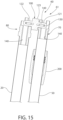
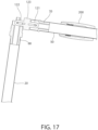
- FIGS. 15-24 show a sequential views of a method for operating tool 11 having the foldable elongated tool handle 10 discloses herein. These figures illustrate changing the tool handle 10 from the folded storage configuration or condition to the operational unfolded configuration or condition.
- FIGS. 15 and 16 shown the tool handle 10 started in the folded configuration or condition described before.
- Upper handle member 50 is laterally offset from and adjacent to the lower handle member 20 in side-by-side relationship.
- Toggle linkage 100 spatially displaces the two handle members, which may be arranged substantially parallel to each other (recognizing that some angular deviation may existing in their relative positioning).
- the arm portions 121, 122 of the toggle linkage are locked in channels 113 of each coupler fitting 70, 80 to help maintain the position of the handle members (see also FIG. 7 for additional detail)
- Locking collar 200 is loosely retained on the upper handle member.
- the upper handle member 50 is rotated upwards by the user about coupler fitting 80 of the lower handle member 20.
- the upper handle member may rotate about its pivot pin 130 and toggle linkage slot 140 assembly and/or the same pivot assembly on the lower handle member. Due to the double-jointed hinge mechanism 60, any of these motions is possible.
- arm portion 121 of the toggle linkage 100 may become axially aligned with it mating locking passage 140 of the upper coupler fitting 70 as shown. This alignment can be produced later in the sequence in other embodiment and does not affect the process of coupling the upper handle member to the lower handle member.
- the upper handle member 50 continues to be rotated upwards until it is coaxially aligned with the lower handle member 20 and the longitudinal axis LA of the handle 10 (see also FIGS. 5-6 and 9-11 ).
- the toggle linkage 100 and its arm portions 121, 122 are axially aligned with the longitudinal axis and handle members.
- each arm portions 121, 122 is initially slideably inserted into and frictionally engages its respective axially aligned elongated locking passage 130 as shown during this motion.
- the upper handle member 50 is pushed further towards the lower handle member 20 until the upper and lower coupler fittings 70, 80 are fully engaged as shown in FIGS. 23 and 24 .
- the arm portions 121, 122 of toggle linkage 100 are inserted and positioned into further engagement with their respective locking passages of coupler fittings 70, 80.
- the axial protrusions 110 of upper fitting 70 are fully nested and engaged with the axial protrusions 110 of lower fitting 80, thereby forming an interlocked arrangement or relationship which is resistant to twisting or torsional forces acting about the longitudinal axis LA at the hinged joint 61 when the tool is used.
- the block-shaped central or middle portion 123 of cruciform shaped toggle linkage 100 is inserted into the lateral locking channel 113 of the upper and lower coupler fittings 70, 80.
- the foregoing forms three of the locking features of the hinged joint 61.
- the final step of securing the double-jointed hinged joint 61 involves sliding the locking collar 200 over the joint and threading the collar onto lower coupler fitting 80.
- the collar is rotated until the threaded engagement is fully tightened to releasably lock the collar onto the join.
- the inward facing annular surfaces inside collar 200 frictionally engage the frustoconical annular flange 84 of the lower coupler fitting 80 to further secure the engagement.
- the upper handle member 50 is now fully locked to the lower handle member 20, and the tool 11 is ready for use.
- tool handle 10 may be converted back to the folded configuration or condition after use by simply reversing the foregoing steps.
- FIG. 12 shows the tool handle 10 in the straight operational and unfolded configuration or condition having an axial length D1 measured from the top of upper handle member 50 to the head frame 43 of the implement 30.
- FIG. 13 shows the tool handle 10 in the folded configuration or condition for storage and packaging having an axial length D2 measured from the top of the articulated joint 61 which is less than D1.
- D2 is about one half D1 in this example; however, in other examples D2 may be greater or less than one half D1.
- more than one joint 61 and hinge mechanism 60 may be used to produce an even shorter and more compact folded configuration of the handle 10 for storage, packaging, and/or shipping.
- the unique double-jointed articulated joint 61 may be used with tool handles that are longer than a typical broom or mop handle disclosed herein by using multiple joints 61. These additional joints 61 may be spaced apart on the long handle at intervals selected to achieve the final collapsed and folded height of the handle desired.
- One non-limiting example of such a long-handled tool is a commercial light bulb changer pole which may be about 3,35 m (11 feet) or more in total assembled length. This contrasts to a typical broom or mop handle which be about 1,06m to 1,22 m (3.5 to 4 feet) in length. Accordingly, the present invention is not limited to use of a single hinge joint.
- the present invention may be used with a wide and virtually unlimited variety and types of tools that may benefit from a collapsible and foldable tool handle having a sturdy and rotationally resistant hinged joint construction having multiple interlocking features.
- Some non-limiting examples include construction or camping tools such as shovels. Accordingly, the present invention is expressly not limited for use with any particular type of implement attached to a jointed handle.
- the upper and lower handle member 20, 50 may be formed of metal or alternatively a suitable rigid polymer.
- the coupler fittings 70, 80, toggle linkage 100, and hinge collar 200 may be formed of injection molded rigid polymers.
- the pins used if any preferably may be metal.
- Rigid polymers and/or semi-rigid elastomeric polymers may be used for the handle end cap 201 and frame of the implement 30.
- Other suitable materials may be used and does limit the invention.
Landscapes
- Engineering & Computer Science (AREA)
- Mechanical Engineering (AREA)
- Cleaning Implements For Floors, Carpets, Furniture, Walls, And The Like (AREA)
- Scissors And Nippers (AREA)
- Purses, Travelling Bags, Baskets, Or Suitcases (AREA)
Claims (11)
- Klappbarer, länglicher Werkzeuggriff (10) zur kompakten Aufbewahrung eines Werkzeugs (30), wobei der Griff umfasst:eine Längsachse (LA);ein längliches erstes Griffelement (20), umfassend ein erstes distales Ende (22), das zur Verbindung mit einem Werkzeug (30) konfiguriert ist, und ein erstes proximales Ende (28);einen ersten Kupplungsbeschlag (80), der starr mit dem ersten Griffelement (20) gekoppelt ist und ein erstes Befestigungsende (81), das in das erste proximale Ende (22) des ersten Griffelements eingesetzt ist, und ein gegenüberliegendes zahnförmiges erstes Kupplungsende (82) umfasst, das einen quer ausgerichteten ersten Verriegelungskanal (113) definiert, wobei der erste Kupplungsbeschlag auch einen axial länglichen ersten zentralen axialen Durchgang (140) umfasst, der sich in dem ersten Befestigungsende (81) von dem ersten Verriegelungskanal (113) aus in das erste Kupplungsende (82) erstreckt und mit diesem in Verbindung steht;ein längliches zweites Griffelement (50) mit einem zweiten distalen Ende (58);einen zweiten Kupplungsbeschlag (70), der starr mit dem zweiten Griffelement (50) gekoppelt ist und ein zweites Befestigungsende (71), das in das zweite distale Ende (58) des zweiten Griffelements (50) eingesetzt ist, und ein gegenüberliegendes zahnförmiges zweites Kupplungsende (72) umfasst, das einen quer ausgerichteten zweiten Verriegelungskanal (113) definiert, wobei der zweite Kupplungsbeschlag (70) auch einen axial länglichen zweiten zentralen axialen Durchgang (140) umfasst, der sich in dem zweitem Befestigungsende (71) von dem zweiten Verriegelungskanal (113) aus in das zweite Kupplungsende (72) erstreckt und mit diesem in Verbindung steht;wobei sowohl der erste als auch der zweite Kupplungsbeschlag (80, 70) eine Vielzahl von axialen Vorsprüngen (110-1, 110-2) aufweisen, die sich axial parallel zur Längsachse (LA) erstrecken, wobei die axialen Vorsprünge (110) des ersten Kupplungsbeschlags (80) so konfiguriert sind, dass sie eine verriegelte Anordnung mit den axialen Vorsprüngen (110) des zweiten Beschlags (70) bilden, um das erste Griffelement (20) relativ zum zweiten Griffelement (50) drehbar zu verriegeln, wenn sich der Griff im ausgeklappten Zustand befindet;wobei jeder der ersten und zweiten Kupplungsbeschläge (80, 70) ein beabstandetes Paar von ersten axialen Vorsprüngen (110-1) aufweist, die eine offene Verriegelungsaufnahme (110-3) dazwischen definieren;wobei sowohl die ersten als auch die zweiten Kupplungsbeschläge (80, 70) einen zweiten axialen Vorsprung (110-2) aufweisen, der diametral gegenüber der offenen Verriegelungsaufnahme (110-3) angeordnet und so konfiguriert ist, dass er in die offene Verriegelungsaufnahme (110-3) eingreift, wenn das längliche erste Griffelement (20) und das längliche zweite Griffelement (50) koaxial entlang der Längsachse (LA) ausgerichtet sind;wobei die ersten und zweiten Verriegelungskanäle (113) zwischen den ersten axialen Vorsprüngen (110-1) und den zweiten axialen Vorsprüngen (110-2) des entsprechenden Kupplungsbeschlags (80, 70) definiert sind;wobei die zweiten Kupplungsenden (82, 72) des ersten und zweiten Griffelements (80, 70) an einem ersten Gelenk (61) über ein längliches Kniehebelgestänge (100) gelenkig miteinander verbunden sind;wobei das Kniehebelgestänge (100) einen starren Körper aufweist, der einen ersten Armabschnitt (121) gegenüber einem zweiten Armabschnitt (122) und einen zentralen Mittelabschnitt (123) dazwischen umfasst;der erste Armabschnitt (121) des Kniehebelgestänges (100) gleitend in den ersten zentralen axialen Durchgang (140) im ersten Kupplungsende (82) des ersten Kupplungsbeschlags (80) einsetzbar ist, und der zweite Armabschnitt (122) des Kniehebelgestänges (100) gleitend in den zweiten zentralen axialen Durchgang (140) im zweiten Kupplungsende (72) des zweiten Kupplungsbeschlags (70) einsetzbar ist;einen ersten Drehzapfen (130), der sich quer durch den ersten Kupplungsabschnitt (82) des ersten Kupplungsbeschlags (80) und einen ersten länglichen Schlitz (120) in dem Kniehebelgestänge (100) erstreckt, und einen zweiten Drehzapfen (130), der sich quer durch den zweiten Kupplungsabschnitt (72) des zweiten Kupplungsbeschlags (70) und einen zweiten länglichen Schlitz (120) in dem Kniehebelgestänge (100) erstreckt;der Griff (10) ist durch Betätigung des Kniehebelgestänges (100) veränderbar zwischen:(i) einem ausgeklappten Zustand, in dem das erste und das zweite Griffelement (20, 50) koaxial mit der Längsachse (LA) ausgerichtet sind, und(ii) einem eingeklappten Zustand, in dem das zweite Griffelement (50) seitlich versetzt von der Längsachse neben dem ersten Griffelement (20) angeordnet ist;wobei der erste und der zweite Armabschnitt (121, 122) des Kniehebelgestänges (100) in den ersten bzw. den zweiten zentralen axialen Durchgang (140, 140) eingeführt und darin verriegelt sind, wenn sich der Griff (10) im ausgeklappten Zustand befindet, um ein Verdrehen des Kniehebelgestänges (100) um die Längsachse (LA) relativ zu dem ersten und dem zweiten Griffelement (20, 50) zu verhindern, die durch das Kniehebelgestänge (100) in koaxialer Ausrichtung gehalten werden;wobei, wenn sich der Griff (10) im eingeklappten Zustand befindet, die ersten und zweiten Armabschnitte (121, 122) des Kniehebelgestänges (100) aus den ersten und zweiten zentralen axialen Durchgängen (140, 140) in den ersten und zweiten Kupplungsenden (82, 72) der ersten bzw. zweiten Kupplungsbeschläge (80, 70) entfernt sind;wobei die ersten und zweiten zentralen axialen Durchgänge (140, 140) und die ersten und zweiten Armabschnitte (121, 122) komplementär gestaltete Querschnittsformen aufweisen, die ein Verdrehen des Kniehebelgestänges (100) relativ zu den zweiten Kupplungsenden (82, 72) der ersten bzw. zweiten Kupplungsbeschläge (80, 70) verhindern; undeine Verriegelungsmanschette (200), die entlang des zweiten Griffelements (50) gleitend bewegbar ist, um das Gelenk (61) zu bedecken, wobei die Verriegelungsmanschette (200) so konfiguriert ist, dass sie mit dem ersten Griffelement (20) in Gewindeeingriff kommt, um den Griff in dem ausgeklappten Zustand zu verriegeln.
- Werkzeuggriff nach Anspruch 1, wobei der erste zentrale axiale Durchgang (140) und der erste Armabschnitt (121) des Kniehebelgestänges (100) eine geradlinige Querschnittsform aufweisen, und der zweite zentrale Durchgang (140) und der zweite Armabschnitt (122) des Kniehebelgestänges (100) eine geradlinige Querschnittsform aufweisen.
- Werkzeuggriff nach Anspruch 1, wobei der erste und der zweite zentrale axiale Durchgang (140, 140) jeweils eine axiale Länge aufweisen, die mindestens gleich oder größer ist als die axiale Länge ihrer jeweiligen ersten und zweiten Armabschnitte (121, 122) des Kniehebelgestänges (100) .
- Werkzeuggriff nach Anspruch 1, wobei das Kniehebelgestänge (100) quer zur Längsachse (LA) und relativ zu den ersten und zweiten Griffelementen (20, 50) schwenkbar beweglich ist, wenn die ersten und zweiten Armabschnitte (121, 122) aus ihren jeweiligen ersten und zweiten zentralen axialen Durchgängen (140, 140) entfernt sind.
- Werkzeuggriff nach Anspruch 1, wobei:die erste Anordnung aus Zapfen (130) und Schlitz (120) den ersten Drehzapfen umfasst, der fest am ersten Kupplungsende (82) des ersten Kupplungsbeschlags (80) angebracht ist, und der erste Schlitz im ersten Armabschnitt (121) des Kniehebelgestänges (100) ausgebildet ist; unddie zweite Anordnung aus Zapfen (130) und Schlitz (120) den zweiten Drehzapfen umfasst, der fest am zweiten Kupplungsende (72) des zweiten Kupplungsbeschlags (70) angebracht ist, und der zweite Schlitz im zweiten Armabschnitt des Kniehebelgestänges (100) ausgebildet ist;wobei das erste Griffelement (20) um den ersten Drehzapfen (130) unabhängig von dem zweiten Griffelement (50) schwenkbar beweglich ist, das um den zweiten Drehzapfen (130) schwenkbar beweglich ist.
- Werkzeuggriff nach Anspruch 5, wobei das Kniehebelgestänge (100) in eine horizontale, quer zur Längsachse (LA) ausgerichtete Position schwenkbar beweglich ist, wenn sich der Werkzeuggriff (10) im eingeklappten Zustand befindet.
- Werkzeuggriff nach einem der vorstehenden Ansprüche, wobei das Kniehebelgestänge (100) einen kreuzförmigen Körper aufweist, umfassend den mittlere Abschnitt (123) des Kniehebelgestänges, der blockförmig ist und in Bezug auf den ersten und zweiten Armabschnitt (121, 122) quer länglich ist.
- Werkzeuggriff nach Anspruch 7, wobei der blockförmige mittlere Abschnitt (123) verriegelbar in den quer ausgerichteten Verriegelungskanal (113) eingreift, der in jedem der ersten und zweiten Kupplungsbeschläge (80, 70) ausgebildet ist, wenn sich der Griff (10) im ausgeklappten Zustand befindet.
- Werkzeuggriff nach Anspruch 1, wobei das Werkzeug (30) ein Besenkopf ist.
- Verfahren zum Betreiben eines Werkzeugs mit einem klappbaren, länglichen Werkzeuggriff (10) nach einem der vorstehenden Ansprüche, wobei das Verfahren umfasst:Drehen des ersten Griffelements (20) um das Gelenk (61) in koaxiale Ausrichtung zum zweiten Griffelement (50);Einsetzen des ersten Armabschnitts (121) des Kniehebelgestänges (100) in den ersten axialen Durchgang (140) des ersten Kupplungsendes (82) des ersten Kupplungsbeschlags (80), wobei der erste Armabschnitt (121) eine geradlinige Querschnittsform aufweist, die verriegelnd in die komplementär konfigurierte Querschnittsform des ersten axialen Durchgangs (140) eingreift;Einsetzen des zweiten Armabschnitts (122) des Kniehebelgestänges (100) in den zweiten axialen Durchgang (140) des zweiten Kupplungsendes (72) des zweiten Kupplungsbeschlags (70), wobei der zweite Armabschnitt (122) eine geradlinige Querschnittsform aufweist, die verriegelnd in die komplementär konfigurierte Querschnittsform des zweiten axialen Durchgangs (140) eingreift; undEinsetzen der zweiten axialen Vorsprünge (110-2) des einen zwischen dem ersten und zweiten Kupplungsbeschlag (80, 70) in die offene Verriegelungsaufnahme (110-3) des anderen zwischen dem ersten und zweiten Kupplungsbeschlag (80, 70), um eine verriegelte Anordnung zu bilden;wobei das erste Griffelement (20), das mit dem zweiten Griffelement (50) in koaxialer Ausrichtung gekoppelt ist, einen ausgeklappten Zustand definiert.
- Verfahren nach Anspruch 10, ferner umfassend das Einsetzen eines blockförmigen mittleren Abschnitts (124) des Kniehebelgestänges (100), das zwischen dem ersten und dem zweiten Armabschnitt (121, 122) angeordnet ist, in den quer ausgerichteten Verriegelungskanal (113), der im ersten und im zweiten Kupplungsende (82, 72) der ersten und zweiten Kupplungsbeschläge (80, 70) ausgebildet ist; und das Schieben einer rohrförmigen Verriegelungsmanschette (200) über das Gelenk (61) und das In-Gewindeeingriffbringen der Verriegelungsmanschette mit dem zweiten Kupplungsende des ersten Griffelements (20).
Applications Claiming Priority (2)
| Application Number | Priority Date | Filing Date | Title |
|---|---|---|---|
| US201862632130P | 2018-02-19 | 2018-02-19 | |
| PCT/US2019/018555 WO2019161379A1 (en) | 2018-02-19 | 2019-02-19 | Collapsible handle for a tool |
Publications (3)
| Publication Number | Publication Date |
|---|---|
| EP3755910A1 EP3755910A1 (de) | 2020-12-30 |
| EP3755910A4 EP3755910A4 (de) | 2021-11-03 |
| EP3755910B1 true EP3755910B1 (de) | 2024-12-25 |
Family
ID=67617178
Family Applications (1)
| Application Number | Title | Priority Date | Filing Date |
|---|---|---|---|
| EP19754222.8A Active EP3755910B1 (de) | 2018-02-19 | 2019-02-19 | Zusammenklappbarer griff für ein werkzeug |
Country Status (5)
| Country | Link |
|---|---|
| US (1) | US11013312B2 (de) |
| EP (1) | EP3755910B1 (de) |
| CA (1) | CA3091432C (de) |
| MX (1) | MX2020008633A (de) |
| WO (1) | WO2019161379A1 (de) |
Families Citing this family (13)
| Publication number | Priority date | Publication date | Assignee | Title |
|---|---|---|---|---|
| US12022770B2 (en) * | 2018-03-02 | 2024-07-02 | Techtronic Outdoor Products Technology Limited | Coupler for a tool |
| CA3009220A1 (en) * | 2018-06-22 | 2019-12-22 | Normand Savard | Snow-removal device with articulated handle |
| US11089860B2 (en) * | 2018-12-12 | 2021-08-17 | David Henry Paratore | Tool for servicing a structure |
| CN211511683U (zh) * | 2019-11-06 | 2020-09-18 | 嘉兴捷顺旅游制品有限公司 | 用于手杆的分段相连结构 |
| CN111481130B (zh) | 2020-05-28 | 2025-08-19 | 浙江贝特日用品有限公司 | 一种锁紧式拖把杆 |
| JP1691323S (de) * | 2021-02-12 | 2021-07-26 | ||
| CN116267177A (zh) * | 2021-12-07 | 2023-06-23 | 南京泉峰科技有限公司 | 动力工具及折叠杆组件 |
| USD977216S1 (en) * | 2022-04-12 | 2023-01-31 | Wuyi Zhisen household products Co., Ltd. | Broom and dustpan set |
| AU2024200955A1 (en) * | 2023-02-17 | 2024-09-05 | Techtronic Cordless Gp | Boom coupler |
| USD1071691S1 (en) * | 2023-10-18 | 2025-04-22 | Xiamen Sengu Sports Equipment Co., Ltd. | Football door folding joint |
| USD1123283S1 (en) * | 2024-01-31 | 2026-04-21 | Unger Marketing International, Llc | Water-fed broom |
| USD1093796S1 (en) * | 2024-02-06 | 2025-09-16 | Tai'an Yunkal Aquarium Equipment Co., Ltd. | Cleaning tool |
| USD1096037S1 (en) * | 2024-03-20 | 2025-09-30 | Taian Qanvee Aquarium Equipment CO., LTD | Aquarium scraper |
Family Cites Families (48)
| Publication number | Priority date | Publication date | Assignee | Title |
|---|---|---|---|---|
| US1039986A (en) * | 1912-05-16 | 1912-10-01 | Rudgear Merle & Co | Invisible hinge-joint for wall-beds. |
| US1906218A (en) * | 1931-05-26 | 1933-04-25 | Charles E Patchell | Joint construction for shovel handles and the like |
| CH176776A (de) | 1934-06-07 | 1935-04-30 | Studer Henri | Vorrichtung zur verkürzenden Zusammenlegung von länglichen Gegenständen. |
| US3380097A (en) | 1967-07-24 | 1968-04-30 | Painter Corp E Z | Extension handle for paint roller |
| US3778610A (en) | 1972-12-04 | 1973-12-11 | L Wolf | Adjustable joint for electrical fixtures |
| CA1038569A (en) * | 1977-01-11 | 1978-09-19 | Her Majesty The Queen In Right Of Canada As Represented By The Minister Of National Defence Of Her Majesty's Canadian Government | Self-locking hinge |
| FR2523501A1 (fr) | 1982-03-19 | 1983-09-23 | Bochaton Pierre | Manche pour outil a main |
| US4611945A (en) * | 1985-06-07 | 1986-09-16 | Diego Dennis F | Articulating joint for folding tubular sections |
| GB8728903D0 (en) * | 1987-12-10 | 1988-01-27 | Secr Defence | Folding linkage |
| US4929113A (en) | 1989-05-30 | 1990-05-29 | Sheu Yin Ping | Knuckle joint |
| US5217315A (en) * | 1992-07-09 | 1993-06-08 | Lifeport, Inc. | Lockable articulating joint and a foldable stretcher frame including same |
| US5417511A (en) | 1993-08-09 | 1995-05-23 | Warden; Roland R. | Releasable lock for telescoping members |
| USD375451S (en) | 1994-07-13 | 1996-11-12 | Yazaki Industrial Chemical Co., Ltd. | Structural joint |
| US5746533A (en) | 1994-10-24 | 1998-05-05 | Schmidt; Todd W. | Lockable hinge mechanism |
| US5887314A (en) | 1997-09-05 | 1999-03-30 | Jordan, Jr.; Leon J. | Telescoping handle with multiple attachment ends |
| US6711783B2 (en) | 1998-11-12 | 2004-03-30 | Lemole John M. | Anti-pinch knuckle for bidirectional sleeve |
| US6371873B1 (en) * | 2000-05-02 | 2002-04-16 | Cheng-Liang Wang | Goal assembly |
| US6532630B1 (en) | 2000-08-04 | 2003-03-18 | Specialty Products Of Greenwood, Missouri, Inc. | Matingly interfitted tool handle and extension for preventing relative rotation |
| US6675546B2 (en) | 2000-10-20 | 2004-01-13 | Total Structures, Inc. | Universal connector |
| US6546596B2 (en) | 2001-01-08 | 2003-04-15 | Rick V. Grote | Extension pole for tools |
| US6776499B2 (en) | 2002-09-17 | 2004-08-17 | Tsung-Chieh Chang | Screw opener with an illumination device |
| GB2395680B (en) | 2002-11-28 | 2004-10-27 | Easy Do Products Ltd | Improvements to handheld utensils for cleaning |
| CN2610836Y (zh) | 2003-03-26 | 2004-04-14 | 刘跃林 | 折叠式拖把 |
| US7003849B2 (en) | 2003-10-29 | 2006-02-28 | Fulcrum Sports, Inc. | Self locking hinge |
| US7549194B2 (en) | 2004-03-19 | 2009-06-23 | Quickie Manufacturing Corporation | Implements with handles and working ends and methods of use thereof |
| US7673365B1 (en) | 2005-04-07 | 2010-03-09 | Griffin Sr Douglas A | Adjustable tool for finishing concrete surfaces |
| US7677619B2 (en) | 2005-10-21 | 2010-03-16 | Grabber Tech, LLC | Collapsible remote mechanical grasper for handling explosive devices |
| CN2850504Y (zh) | 2005-12-20 | 2006-12-27 | 朱雪林 | 一种可弯折的拖把杆 |
| US7356871B2 (en) | 2006-03-21 | 2008-04-15 | Jonathan Mark Heaven | Dual sized broom and dust pan |
| US8566999B1 (en) | 2009-11-09 | 2013-10-29 | Gordon C. Casey | Extension for paint brush handle |
| US20110119846A1 (en) | 2009-11-25 | 2011-05-26 | Gerard Stokes | Broom |
| USD660535S1 (en) | 2011-05-13 | 2012-05-22 | Menius Marvin L | Cleaning device |
| USD667598S1 (en) | 2011-10-19 | 2012-09-18 | Menius Marvin L | Cleaning device |
| CN202355361U (zh) | 2011-11-09 | 2012-08-01 | 刘王楚齐 | 折叠扫帚 |
| USD719712S1 (en) | 2012-09-07 | 2014-12-16 | Diversey, Inc. | Floor maintenance tool |
| USD699412S1 (en) | 2012-09-21 | 2014-02-11 | Chad Smith | Combined broom and dustpan |
| US20170282348A1 (en) | 2012-12-27 | 2017-10-05 | Moshe Mark | Multipurpose cleaning tool having an interchangable head |
| USD714613S1 (en) | 2013-09-19 | 2014-10-07 | Melvin Duane Jenkins | Master handle with hanger |
| US9915081B2 (en) * | 2013-12-13 | 2018-03-13 | NTH Innovations, LLC | Connection apparatus, system, and methods for collapsible structures |
| US10633885B2 (en) * | 2013-12-13 | 2020-04-28 | NTH Innovations, LLC | Connection apparatus, system, and methods for collapsible structures |
| USD782273S1 (en) | 2016-01-27 | 2017-03-28 | Leader Motorsports Accessories, Inc. | Articulatable joint for accessory mount |
| US10076221B2 (en) | 2016-02-08 | 2018-09-18 | Natasha Cook | Cleaning device for bathroom cleaning applications |
| CN206151385U (zh) | 2016-06-21 | 2017-05-10 | 巢湖学院 | 一种折叠伸缩的扫帚 |
| CN106725148A (zh) | 2016-12-27 | 2017-05-31 | 贵州开阳兴茂农业开发有限责任公司 | 一种可折叠的扫把 |
| DE212018000165U1 (de) | 2017-02-27 | 2019-10-28 | Wolfgang Held | Stange für Geräte |
| USD825306S1 (en) | 2017-04-14 | 2018-08-14 | Madi, Llc | Tool attachment interface |
| USD834915S1 (en) * | 2017-07-19 | 2018-12-04 | Dazadi, Inc. | Tube hinge |
| US10641319B2 (en) * | 2017-11-07 | 2020-05-05 | Benjamin Chen | Elbow joint device for goal assembling |
-
2019
- 2019-02-19 CA CA3091432A patent/CA3091432C/en active Active
- 2019-02-19 EP EP19754222.8A patent/EP3755910B1/de active Active
- 2019-02-19 WO PCT/US2019/018555 patent/WO2019161379A1/en not_active Ceased
- 2019-02-19 US US16/279,255 patent/US11013312B2/en active Active
- 2019-02-19 MX MX2020008633A patent/MX2020008633A/es unknown
Also Published As
| Publication number | Publication date |
|---|---|
| EP3755910A4 (de) | 2021-11-03 |
| MX2020008633A (es) | 2020-12-09 |
| CA3091432A1 (en) | 2019-08-22 |
| EP3755910A1 (de) | 2020-12-30 |
| CA3091432C (en) | 2022-12-13 |
| US20190254411A1 (en) | 2019-08-22 |
| WO2019161379A1 (en) | 2019-08-22 |
| US11013312B2 (en) | 2021-05-25 |
Similar Documents
| Publication | Publication Date | Title |
|---|---|---|
| EP3755910B1 (de) | Zusammenklappbarer griff für ein werkzeug | |
| US6925686B2 (en) | Twist-lock handle assembly | |
| US6216717B1 (en) | Collapsible tent frame | |
| US8910648B2 (en) | Connector device for a foldable tent | |
| US5127762A (en) | Connector assembly | |
| US20110252591A1 (en) | Folding broom | |
| JPH06504104A (ja) | 非圧縮性ピボットを備えたシザー端部が捕獲された折畳み可能なキャノピー骨組構造体 | |
| US6088868A (en) | Folding compact push broom | |
| US20130014794A1 (en) | Foldable tent | |
| CA2844760C (en) | Locking joint for collapsible ladders and other structures | |
| AU2003277787A1 (en) | Push-lock handle assembly | |
| AU2005202137A1 (en) | Locking, segmented cleaning implement handle | |
| US20230074662A1 (en) | Modular Scaffolds, Scaffold Kits and Methods of Use Therefor | |
| AU2012280086B2 (en) | Collapsible cleaning device | |
| CN101392627A (zh) | 一种可兼作脚手架的梯子 | |
| CN201297027Y (zh) | 一种可兼作脚手架的梯子 | |
| US7600276B2 (en) | Baby crib including a top frame unit that can be disassembled | |
| RU2719514C1 (ru) | Коленчатая рукоятка в сборе | |
| CA2327214C (en) | Collapsible tent frame | |
| JP3667309B2 (ja) | 折り畳み支持脚及びこれを用いたテーブル | |
| JPS608809B2 (ja) | 人造クリスマスツリ− | |
| CA2779782A1 (en) | Foldable tent | |
| KR200441655Y1 (ko) | 다기능 접철식 사다리 | |
| CN101892646B (zh) | 雪耙及其具有防止松动附件的工具杆 | |
| KR200323755Y1 (ko) | 연결부에 의해서 길이조절이 가능한 다기능 작업대 |
Legal Events
| Date | Code | Title | Description |
|---|---|---|---|
| STAA | Information on the status of an ep patent application or granted ep patent |
Free format text: STATUS: THE INTERNATIONAL PUBLICATION HAS BEEN MADE |
|
| PUAI | Public reference made under article 153(3) epc to a published international application that has entered the european phase |
Free format text: ORIGINAL CODE: 0009012 |
|
| STAA | Information on the status of an ep patent application or granted ep patent |
Free format text: STATUS: REQUEST FOR EXAMINATION WAS MADE |
|
| 17P | Request for examination filed |
Effective date: 20200917 |
|
| AK | Designated contracting states |
Kind code of ref document: A1 Designated state(s): AL AT BE BG CH CY CZ DE DK EE ES FI FR GB GR HR HU IE IS IT LI LT LU LV MC MK MT NL NO PL PT RO RS SE SI SK SM TR |
|
| AX | Request for extension of the european patent |
Extension state: BA ME |
|
| RIN1 | Information on inventor provided before grant (corrected) |
Inventor name: DUTTON, MIA Inventor name: STANISZEWSKI, MEGAN |
|
| DAV | Request for validation of the european patent (deleted) | ||
| DAX | Request for extension of the european patent (deleted) | ||
| REG | Reference to a national code |
Ref country code: DE Ref legal event code: R079 Free format text: PREVIOUS MAIN CLASS: F16C0011100000 Ipc: B25G0001040000 Ref country code: DE Ref legal event code: R079 Ref document number: 602019063963 Country of ref document: DE Free format text: PREVIOUS MAIN CLASS: F16C0011100000 Ipc: B25G0001040000 |
|
| A4 | Supplementary search report drawn up and despatched |
Effective date: 20211001 |
|
| RIC1 | Information provided on ipc code assigned before grant |
Ipc: A46B 5/00 20060101ALI20210927BHEP Ipc: F16M 11/26 20060101ALI20210927BHEP Ipc: B25G 1/04 20060101AFI20210927BHEP |
|
| STAA | Information on the status of an ep patent application or granted ep patent |
Free format text: STATUS: EXAMINATION IS IN PROGRESS |
|
| 17Q | First examination report despatched |
Effective date: 20230921 |
|
| REG | Reference to a national code |
Ref country code: DE Ref legal event code: R079 Free format text: PREVIOUS MAIN CLASS: B25G0001040000 Ipc: A46B0005000000 Ref country code: DE Ref legal event code: R079 Ref document number: 602019063963 Country of ref document: DE Free format text: PREVIOUS MAIN CLASS: B25G0001040000 Ipc: A46B0005000000 |
|
| GRAP | Despatch of communication of intention to grant a patent |
Free format text: ORIGINAL CODE: EPIDOSNIGR1 |
|
| STAA | Information on the status of an ep patent application or granted ep patent |
Free format text: STATUS: GRANT OF PATENT IS INTENDED |
|
| RIC1 | Information provided on ipc code assigned before grant |
Ipc: F16M 11/26 20060101ALI20240710BHEP Ipc: B25G 3/38 20060101ALI20240710BHEP Ipc: B25G 1/04 20060101ALI20240710BHEP Ipc: A46B 5/00 20060101AFI20240710BHEP |
|
| INTG | Intention to grant announced |
Effective date: 20240724 |
|
| GRAS | Grant fee paid |
Free format text: ORIGINAL CODE: EPIDOSNIGR3 |
|
| GRAA | (expected) grant |
Free format text: ORIGINAL CODE: 0009210 |
|
| STAA | Information on the status of an ep patent application or granted ep patent |
Free format text: STATUS: THE PATENT HAS BEEN GRANTED |
|
| P01 | Opt-out of the competence of the unified patent court (upc) registered |
Free format text: CASE NUMBER: APP_56723/2024 Effective date: 20241017 |
|
| AK | Designated contracting states |
Kind code of ref document: B1 Designated state(s): AL AT BE BG CH CY CZ DE DK EE ES FI FR GB GR HR HU IE IS IT LI LT LU LV MC MK MT NL NO PL PT RO RS SE SI SK SM TR |
|
| REG | Reference to a national code |
Ref country code: GB Ref legal event code: FG4D |
|
| REG | Reference to a national code |
Ref country code: CH Ref legal event code: EP |
|
| REG | Reference to a national code |
Ref country code: DE Ref legal event code: R096 Ref document number: 602019063963 Country of ref document: DE |
|
| REG | Reference to a national code |
Ref country code: IE Ref legal event code: FG4D |
|
| REG | Reference to a national code |
Ref country code: LT Ref legal event code: MG9D |
|
| PG25 | Lapsed in a contracting state [announced via postgrant information from national office to epo] |
Ref country code: HR Free format text: LAPSE BECAUSE OF FAILURE TO SUBMIT A TRANSLATION OF THE DESCRIPTION OR TO PAY THE FEE WITHIN THE PRESCRIBED TIME-LIMIT Effective date: 20241225 |
|
| PG25 | Lapsed in a contracting state [announced via postgrant information from national office to epo] |
Ref country code: FI Free format text: LAPSE BECAUSE OF FAILURE TO SUBMIT A TRANSLATION OF THE DESCRIPTION OR TO PAY THE FEE WITHIN THE PRESCRIBED TIME-LIMIT Effective date: 20241225 |
|
| PG25 | Lapsed in a contracting state [announced via postgrant information from national office to epo] |
Ref country code: BG Free format text: LAPSE BECAUSE OF FAILURE TO SUBMIT A TRANSLATION OF THE DESCRIPTION OR TO PAY THE FEE WITHIN THE PRESCRIBED TIME-LIMIT Effective date: 20241225 |
|
| PG25 | Lapsed in a contracting state [announced via postgrant information from national office to epo] |
Ref country code: NO Free format text: LAPSE BECAUSE OF FAILURE TO SUBMIT A TRANSLATION OF THE DESCRIPTION OR TO PAY THE FEE WITHIN THE PRESCRIBED TIME-LIMIT Effective date: 20250325 |
|
| PG25 | Lapsed in a contracting state [announced via postgrant information from national office to epo] |
Ref country code: LV Free format text: LAPSE BECAUSE OF FAILURE TO SUBMIT A TRANSLATION OF THE DESCRIPTION OR TO PAY THE FEE WITHIN THE PRESCRIBED TIME-LIMIT Effective date: 20241225 Ref country code: GR Free format text: LAPSE BECAUSE OF FAILURE TO SUBMIT A TRANSLATION OF THE DESCRIPTION OR TO PAY THE FEE WITHIN THE PRESCRIBED TIME-LIMIT Effective date: 20250326 |
|
| PG25 | Lapsed in a contracting state [announced via postgrant information from national office to epo] |
Ref country code: RS Free format text: LAPSE BECAUSE OF FAILURE TO SUBMIT A TRANSLATION OF THE DESCRIPTION OR TO PAY THE FEE WITHIN THE PRESCRIBED TIME-LIMIT Effective date: 20250325 |
|
| REG | Reference to a national code |
Ref country code: NL Ref legal event code: MP Effective date: 20241225 |
|
| PG25 | Lapsed in a contracting state [announced via postgrant information from national office to epo] |
Ref country code: NL Free format text: LAPSE BECAUSE OF FAILURE TO SUBMIT A TRANSLATION OF THE DESCRIPTION OR TO PAY THE FEE WITHIN THE PRESCRIBED TIME-LIMIT Effective date: 20241225 |
|
| REG | Reference to a national code |
Ref country code: AT Ref legal event code: MK05 Ref document number: 1753427 Country of ref document: AT Kind code of ref document: T Effective date: 20241225 |
|
| PG25 | Lapsed in a contracting state [announced via postgrant information from national office to epo] |
Ref country code: SM Free format text: LAPSE BECAUSE OF FAILURE TO SUBMIT A TRANSLATION OF THE DESCRIPTION OR TO PAY THE FEE WITHIN THE PRESCRIBED TIME-LIMIT Effective date: 20241225 |
|
| PG25 | Lapsed in a contracting state [announced via postgrant information from national office to epo] |
Ref country code: PL Free format text: LAPSE BECAUSE OF FAILURE TO SUBMIT A TRANSLATION OF THE DESCRIPTION OR TO PAY THE FEE WITHIN THE PRESCRIBED TIME-LIMIT Effective date: 20241225 |
|
| PG25 | Lapsed in a contracting state [announced via postgrant information from national office to epo] |
Ref country code: ES Free format text: LAPSE BECAUSE OF FAILURE TO SUBMIT A TRANSLATION OF THE DESCRIPTION OR TO PAY THE FEE WITHIN THE PRESCRIBED TIME-LIMIT Effective date: 20241225 |
|
| PG25 | Lapsed in a contracting state [announced via postgrant information from national office to epo] |
Ref country code: IS Free format text: LAPSE BECAUSE OF FAILURE TO SUBMIT A TRANSLATION OF THE DESCRIPTION OR TO PAY THE FEE WITHIN THE PRESCRIBED TIME-LIMIT Effective date: 20250425 |
|
| PG25 | Lapsed in a contracting state [announced via postgrant information from national office to epo] |
Ref country code: PT Free format text: LAPSE BECAUSE OF FAILURE TO SUBMIT A TRANSLATION OF THE DESCRIPTION OR TO PAY THE FEE WITHIN THE PRESCRIBED TIME-LIMIT Effective date: 20250428 |
|
| PG25 | Lapsed in a contracting state [announced via postgrant information from national office to epo] |
Ref country code: EE Free format text: LAPSE BECAUSE OF FAILURE TO SUBMIT A TRANSLATION OF THE DESCRIPTION OR TO PAY THE FEE WITHIN THE PRESCRIBED TIME-LIMIT Effective date: 20241225 |
|
| PG25 | Lapsed in a contracting state [announced via postgrant information from national office to epo] |
Ref country code: RO Free format text: LAPSE BECAUSE OF FAILURE TO SUBMIT A TRANSLATION OF THE DESCRIPTION OR TO PAY THE FEE WITHIN THE PRESCRIBED TIME-LIMIT Effective date: 20241225 Ref country code: AT Free format text: LAPSE BECAUSE OF FAILURE TO SUBMIT A TRANSLATION OF THE DESCRIPTION OR TO PAY THE FEE WITHIN THE PRESCRIBED TIME-LIMIT Effective date: 20241225 |
|
| PG25 | Lapsed in a contracting state [announced via postgrant information from national office to epo] |
Ref country code: SK Free format text: LAPSE BECAUSE OF FAILURE TO SUBMIT A TRANSLATION OF THE DESCRIPTION OR TO PAY THE FEE WITHIN THE PRESCRIBED TIME-LIMIT Effective date: 20241225 |
|
| PG25 | Lapsed in a contracting state [announced via postgrant information from national office to epo] |
Ref country code: CZ Free format text: LAPSE BECAUSE OF FAILURE TO SUBMIT A TRANSLATION OF THE DESCRIPTION OR TO PAY THE FEE WITHIN THE PRESCRIBED TIME-LIMIT Effective date: 20241225 |
|
| PG25 | Lapsed in a contracting state [announced via postgrant information from national office to epo] |
Ref country code: IT Free format text: LAPSE BECAUSE OF FAILURE TO SUBMIT A TRANSLATION OF THE DESCRIPTION OR TO PAY THE FEE WITHIN THE PRESCRIBED TIME-LIMIT Effective date: 20241225 |
|
| PG25 | Lapsed in a contracting state [announced via postgrant information from national office to epo] |
Ref country code: SE Free format text: LAPSE BECAUSE OF FAILURE TO SUBMIT A TRANSLATION OF THE DESCRIPTION OR TO PAY THE FEE WITHIN THE PRESCRIBED TIME-LIMIT Effective date: 20241225 |
|
| PG25 | Lapsed in a contracting state [announced via postgrant information from national office to epo] |
Ref country code: MC Free format text: LAPSE BECAUSE OF FAILURE TO SUBMIT A TRANSLATION OF THE DESCRIPTION OR TO PAY THE FEE WITHIN THE PRESCRIBED TIME-LIMIT Effective date: 20241225 |
|
| REG | Reference to a national code |
Ref country code: DE Ref legal event code: R097 Ref document number: 602019063963 Country of ref document: DE |
|
| REG | Reference to a national code |
Ref country code: CH Ref legal event code: PL |
|
| PG25 | Lapsed in a contracting state [announced via postgrant information from national office to epo] |
Ref country code: DK Free format text: LAPSE BECAUSE OF FAILURE TO SUBMIT A TRANSLATION OF THE DESCRIPTION OR TO PAY THE FEE WITHIN THE PRESCRIBED TIME-LIMIT Effective date: 20241225 |
|
| PG25 | Lapsed in a contracting state [announced via postgrant information from national office to epo] |
Ref country code: LU Free format text: LAPSE BECAUSE OF NON-PAYMENT OF DUE FEES Effective date: 20250219 |
|
| PG25 | Lapsed in a contracting state [announced via postgrant information from national office to epo] |
Ref country code: CH Free format text: LAPSE BECAUSE OF NON-PAYMENT OF DUE FEES Effective date: 20250228 |
|
| PLBE | No opposition filed within time limit |
Free format text: ORIGINAL CODE: 0009261 |
|
| STAA | Information on the status of an ep patent application or granted ep patent |
Free format text: STATUS: NO OPPOSITION FILED WITHIN TIME LIMIT |
|
| 26N | No opposition filed |
Effective date: 20250926 |
|
| REG | Reference to a national code |
Ref country code: BE Ref legal event code: MM Effective date: 20250228 |
|
| PG25 | Lapsed in a contracting state [announced via postgrant information from national office to epo] |
Ref country code: BE Free format text: LAPSE BECAUSE OF NON-PAYMENT OF DUE FEES Effective date: 20250228 |
|
| PG25 | Lapsed in a contracting state [announced via postgrant information from national office to epo] |
Ref country code: IE Free format text: LAPSE BECAUSE OF NON-PAYMENT OF DUE FEES Effective date: 20250219 |
|
| PGFP | Annual fee paid to national office [announced via postgrant information from national office to epo] |
Ref country code: GB Payment date: 20260223 Year of fee payment: 8 |
|
| PGFP | Annual fee paid to national office [announced via postgrant information from national office to epo] |
Ref country code: DE Payment date: 20260220 Year of fee payment: 8 |
|
| PGFP | Annual fee paid to national office [announced via postgrant information from national office to epo] |
Ref country code: FR Payment date: 20260227 Year of fee payment: 8 |