EP3755909B1 - Kugelgelenk, insbesondere für fahrwerksteile eines kraftfahrzeugs - Google Patents
Kugelgelenk, insbesondere für fahrwerksteile eines kraftfahrzeugs Download PDFInfo
- Publication number
- EP3755909B1 EP3755909B1 EP19708793.5A EP19708793A EP3755909B1 EP 3755909 B1 EP3755909 B1 EP 3755909B1 EP 19708793 A EP19708793 A EP 19708793A EP 3755909 B1 EP3755909 B1 EP 3755909B1
- Authority
- EP
- European Patent Office
- Prior art keywords
- bearing shells
- housing
- ball joint
- bearing
- joint according
- Prior art date
- Legal status (The legal status is an assumption and is not a legal conclusion. Google has not performed a legal analysis and makes no representation as to the accuracy of the status listed.)
- Active
Links
Images


Classifications
-
- F—MECHANICAL ENGINEERING; LIGHTING; HEATING; WEAPONS; BLASTING
- F16—ENGINEERING ELEMENTS AND UNITS; GENERAL MEASURES FOR PRODUCING AND MAINTAINING EFFECTIVE FUNCTIONING OF MACHINES OR INSTALLATIONS; THERMAL INSULATION IN GENERAL
- F16C—SHAFTS; FLEXIBLE SHAFTS; ELEMENTS OR CRANKSHAFT MECHANISMS; ROTARY BODIES OTHER THAN GEARING ELEMENTS; BEARINGS
- F16C11/00—Pivots; Pivotal connections
- F16C11/04—Pivotal connections
- F16C11/06—Ball-joints; Other joints having more than one degree of angular freedom, i.e. universal joints
- F16C11/0614—Ball-joints; Other joints having more than one degree of angular freedom, i.e. universal joints the female part of the joint being open on two sides
-
- B—PERFORMING OPERATIONS; TRANSPORTING
- B60—VEHICLES IN GENERAL
- B60G—VEHICLE SUSPENSION ARRANGEMENTS
- B60G7/00—Pivoted suspension arms; Accessories thereof
- B60G7/005—Ball joints
-
- F—MECHANICAL ENGINEERING; LIGHTING; HEATING; WEAPONS; BLASTING
- F16—ENGINEERING ELEMENTS AND UNITS; GENERAL MEASURES FOR PRODUCING AND MAINTAINING EFFECTIVE FUNCTIONING OF MACHINES OR INSTALLATIONS; THERMAL INSULATION IN GENERAL
- F16C—SHAFTS; FLEXIBLE SHAFTS; ELEMENTS OR CRANKSHAFT MECHANISMS; ROTARY BODIES OTHER THAN GEARING ELEMENTS; BEARINGS
- F16C11/00—Pivots; Pivotal connections
- F16C11/04—Pivotal connections
- F16C11/06—Ball-joints; Other joints having more than one degree of angular freedom, i.e. universal joints
- F16C11/0619—Ball-joints; Other joints having more than one degree of angular freedom, i.e. universal joints the female part comprising a blind socket receiving the male part
- F16C11/0623—Construction or details of the socket member
-
- F—MECHANICAL ENGINEERING; LIGHTING; HEATING; WEAPONS; BLASTING
- F16—ENGINEERING ELEMENTS AND UNITS; GENERAL MEASURES FOR PRODUCING AND MAINTAINING EFFECTIVE FUNCTIONING OF MACHINES OR INSTALLATIONS; THERMAL INSULATION IN GENERAL
- F16C—SHAFTS; FLEXIBLE SHAFTS; ELEMENTS OR CRANKSHAFT MECHANISMS; ROTARY BODIES OTHER THAN GEARING ELEMENTS; BEARINGS
- F16C11/00—Pivots; Pivotal connections
- F16C11/04—Pivotal connections
- F16C11/06—Ball-joints; Other joints having more than one degree of angular freedom, i.e. universal joints
- F16C11/0619—Ball-joints; Other joints having more than one degree of angular freedom, i.e. universal joints the female part comprising a blind socket receiving the male part
- F16C11/0623—Construction or details of the socket member
- F16C11/0628—Construction or details of the socket member with linings
- F16C11/0633—Construction or details of the socket member with linings the linings being made of plastics
- F16C11/0638—Construction or details of the socket member with linings the linings being made of plastics characterised by geometrical details
-
- F—MECHANICAL ENGINEERING; LIGHTING; HEATING; WEAPONS; BLASTING
- F16—ENGINEERING ELEMENTS AND UNITS; GENERAL MEASURES FOR PRODUCING AND MAINTAINING EFFECTIVE FUNCTIONING OF MACHINES OR INSTALLATIONS; THERMAL INSULATION IN GENERAL
- F16C—SHAFTS; FLEXIBLE SHAFTS; ELEMENTS OR CRANKSHAFT MECHANISMS; ROTARY BODIES OTHER THAN GEARING ELEMENTS; BEARINGS
- F16C33/00—Parts of bearings; Special methods for making bearings or parts thereof
- F16C33/02—Parts of sliding-contact bearings
- F16C33/04—Brasses; Bushes; Linings
- F16C33/046—Brasses; Bushes; Linings divided or split, e.g. half-bearings or rolled sleeves
-
- F—MECHANICAL ENGINEERING; LIGHTING; HEATING; WEAPONS; BLASTING
- F16—ENGINEERING ELEMENTS AND UNITS; GENERAL MEASURES FOR PRODUCING AND MAINTAINING EFFECTIVE FUNCTIONING OF MACHINES OR INSTALLATIONS; THERMAL INSULATION IN GENERAL
- F16C—SHAFTS; FLEXIBLE SHAFTS; ELEMENTS OR CRANKSHAFT MECHANISMS; ROTARY BODIES OTHER THAN GEARING ELEMENTS; BEARINGS
- F16C33/00—Parts of bearings; Special methods for making bearings or parts thereof
- F16C33/02—Parts of sliding-contact bearings
- F16C33/04—Brasses; Bushes; Linings
- F16C33/06—Sliding surface mainly made of metal
- F16C33/10—Construction relative to lubrication
- F16C33/1025—Construction relative to lubrication with liquid, e.g. oil, as lubricant
- F16C33/106—Details of distribution or circulation inside the bearings, e.g. details of the bearing surfaces to affect flow or pressure of the liquid
- F16C33/1065—Grooves on a bearing surface for distributing or collecting the liquid
-
- F—MECHANICAL ENGINEERING; LIGHTING; HEATING; WEAPONS; BLASTING
- F16—ENGINEERING ELEMENTS AND UNITS; GENERAL MEASURES FOR PRODUCING AND MAINTAINING EFFECTIVE FUNCTIONING OF MACHINES OR INSTALLATIONS; THERMAL INSULATION IN GENERAL
- F16C—SHAFTS; FLEXIBLE SHAFTS; ELEMENTS OR CRANKSHAFT MECHANISMS; ROTARY BODIES OTHER THAN GEARING ELEMENTS; BEARINGS
- F16C2220/00—Shaping
- F16C2220/02—Shaping by casting
- F16C2220/04—Shaping by casting by injection-moulding
-
- F—MECHANICAL ENGINEERING; LIGHTING; HEATING; WEAPONS; BLASTING
- F16—ENGINEERING ELEMENTS AND UNITS; GENERAL MEASURES FOR PRODUCING AND MAINTAINING EFFECTIVE FUNCTIONING OF MACHINES OR INSTALLATIONS; THERMAL INSULATION IN GENERAL
- F16C—SHAFTS; FLEXIBLE SHAFTS; ELEMENTS OR CRANKSHAFT MECHANISMS; ROTARY BODIES OTHER THAN GEARING ELEMENTS; BEARINGS
- F16C2326/00—Articles relating to transporting
- F16C2326/01—Parts of vehicles in general
- F16C2326/05—Vehicle suspensions, e.g. bearings, pivots or connecting rods used therein
Definitions
- the invention relates to a ball joint which has a ball pivot which is accommodated within a housing by means of two bearing shells.
- Ball joints are known in a wide variety of configurations.
- the ball pivot is accommodated in the housing with high pull-out forces, that a precisely defined frictional torque acts between the ball pivot and bearing shell, and that there is little wear.
- a ball joint is known in which the two bearing shells are arranged within a metal housing and then overmoulded with plastic.
- the housing is knurled on the inside so that the plastic is mechanically held within the housing.
- the EP 2 465 713 A1 discloses a ball and socket joint with a two-part bearing in which a ball pivot is mounted and which is encapsulated by a housing, the bearing shells bearing against the ball pivot over their entire surface in a mutual contact area.
- the object of the invention is to create a ball and socket joint that is distinguished by better performance values and can be manufactured at low cost.
- a ball joint is provided according to the invention with a ball pivot, which has a ball section, two bearing shells, each of which has a peripheral edge and are arranged on the ball section in such a way that their peripheral edges face each other at a distance greater than 0, and a housing that consists in one piece of plastic, the two bearing shells being overmoulded with the plastic forming the housing in such a way that they are enclosed by the housing and that they are acted upon by the housing against the ball section.
- This ball joint has low manufacturing costs because the plastic that encloses the two bearing shells acts as a housing that is in direct contact with the two bearing shells and has the necessary strength and stability. No outer casing is required.
- the ball joint according to the invention also has the advantage that the shrinkage of the plastic material with which the bearing shells are encapsulated can be converted in a targeted manner into a contact pressure with which the bearing shells are loaded against the ball section, since the two bearing shells, because of the gap between them, which is free of material, etc., are displaceable in the axial direction relative to the ball section.
- the bearing shells are supported on one another, so that they have to be greatly deformed overall if they are to be pressed against the ball section with a prestressing force.
- the bearing shells have reciprocal engagement sections, so that they are centered in the radial direction and in the circumferential direction, but can be displaced relative to one another in the axial direction.
- the engagement sections ensure that the two bearing shells remain centered relative to one another even when they are arranged in an injection mold and liquid plastic is pressed into the injection mold.
- the engagement sections are designed to be interrupted in the circumferential direction.
- the engagement sections together form an outwardly projecting collar which is firmly enclosed by the material of the housing.
- the collar helps to reliably anchor the two bearing shells within the plastic housing.
- the engagement sections of one bearing shell preferably latch with the other bearing shell. This allows the two bearing shells on the Pre-assemble ball pivot so that it can be arranged with this as an assembly in an injection mold.
- the bearing shells have pocket-shaped depressions on their outside.
- the pocket-shaped indentations result in a targeted reduction in the wall thickness of the bearing shells, so that the flexibility of the bearing shells in the radial direction and thus the contact pressure with which the bearing shells are pressed against the ball section can be adjusted there.
- the wall thickness of the bearing shells at the bottom of the depressions is preferably less than 50% of the wall thickness of the bearing shells between adjacent depressions, so that the elasticity of the bearing shells in the region of the bottom of the pockets is significantly increased.
- the bearing shells are provided with lubricant grooves that open out at the axial ends of the bearing shells. This makes it possible to grease the ball joint later, i.e. after the housing has been sprayed onto the bearing shells.
- the housing can be provided with recesses which extend from the axial end faces toward the center. With the recesses, the rigidity of the housing and thus the preload that is exerted by the housing on the bearing shells can be adjusted in a targeted manner. In addition, the recesses lead to weight savings.
- the housing adheres to the bearing shells. This can be achieved by overmoulding the bearing shells with plastic material that is at a suitable temperature, so that the bearing shells are slightly melted on the outside.
- a material is used for the plastic housing that can form a material connection with the material of the bearing shells.
- the same material is used for the housing as for the bearing shells.
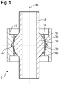
- a ball joint 5 which has a ball pivot 10, two bearing shells 20 and a housing 40 as essential components.
- the ball pivot 10 has a ball section 12 from which a pivot 14 extends at opposite ends.
- the two pins are arranged concentrically to a central axis 16 which also runs through the center point of the ball section 12 .
- the central axis 16 extends through the "poles" of the sphere on which the spherical section 12 is based.
- the outer surface of the spherical section 12 extends along the “equator” of the spherical section 12.
- the “latitude” to which the outer surface of the spherical section 12 extends depends on the diameter of the pin 14. In the exemplary embodiment shown, the outer surface extends up to a level of about ⁇ 40°.
- the ball stud 10 is hollow. In other words: there is a cavity 18 which extends through the two pins 14 and the ball section 12 therethrough.
- the ball pivot 10 consists of metal, in particular steel.
- the two bearing shells 20 are each designed to run around in the circumferential direction. They have an inner peripheral edge 22 and an outer peripheral edge 24 .
- the inner peripheral edge 22 is arranged on the side of the equator of the ball section 12, while the outer peripheral edge 24 is arranged on the side of the pin 14.
- each bearing shell 20 has the shape of a segment of a sphere.
- the bearing shells are made of plastic, with a variety of thermoplastics and duroplastics being used.
- each bearing shell 20 has a plurality of pocket-like depressions 26 on its outside, that is to say on the side facing away from the spherical section 12 .
- Each recess 26 is self-contained, ie has a peripheral edge 28 which delimits the recess 26 from the outside of the bearing shell 20 .
- the depressions 26 serve to reduce the wall thickness of the bearing shells 20 locally.
- the wall thickness s at the bottom of the depressions is less than 50% of the wall thickness of the bearing shells 20 in the area between the depressions 26.
- the dimensions of the wells can be adapted to the respective requirements.
- the height of the indentations, ie measured parallel to the central axis 16 is on the order of 30% of the height of the corresponding bearing shell.
- the distance between adjacent indentations 26, measured in the circumferential direction, is approximately 50% of the width of each indentation 26 in the exemplary embodiment shown.
- each bearing shell 20 has on its inner surface, i.e. the side that is in contact with the outer surface of the ball section 12 cooperates, several lubricant grooves 28 on. These open out at the outer peripheral edge 24.
- the lubricating grooves 28 extend in the direction of lines of longitude on the spherical portion. Alternatively, it is also possible for the lubricant grooves to extend obliquely to the lines of longitude at an angle other than 0°.
- the pocket-like depressions 26 and the lubricant grooves 28 are shown here on different bearing shells 20 .
- the ball joint 5 may have either the pocket-like depressions 26 or the lubricant grooves 28 or both the pocket-like depressions 26 and the lubricant grooves 28.
- the inner peripheral edges 22 of the bearing shells are mutually provided with engagement portions 32,34. “Reciprocally” means here that the engagement sections 32 arranged on one bearing shell 20 interact with the engagement sections 34 which are provided on the other bearing shell 20 .
- an engagement section 32 of a bearing shell 20 is arranged between two adjacent engagement sections 34 of the other bearing shell 20 .
- FIGS Figures 5 and 6 An example of mutually arranged engaging portions 32, 34 is shown in FIGS Figures 5 and 6 shown.
- Each of the bearing shells 20 is provided with narrow webs 32 which protrude in the axial direction and which engage in corresponding slots 34 in the other bearing shell 20 .
- the mutually interacting engagement sections ensure a positive fit between the two bearing shells 20 in the circumferential direction and center them relative to one another. At the same time, they allow the two bearing shells to be displaced relative to one another in the axial direction.
- FIG 7 a further embodiment of the engagement sections 32, 34 is shown.
- the difference to in the Figures 5 and 6 The configuration shown consists in that the engagement sections 32, 34 are designed as outer skirts, which are arranged radially outside of the opposite inner peripheral edges 22 and protrude beyond them in the axial direction toward the opposite bearing shell 20.
- the engagement sections 32 of one bearing shell 20 are as wide in the circumferential direction as the engagement sections 34 of the other bearing shell 20.
- an apron 32 of one bearing shell lies between two adjacent aprons 34 of the other bearing shell.
- the engagement sections 32, 34 are dimensioned with an interference fit or a clearance fit with very little play. Therefore, the aprons 32, 34 close the gap 30 between the bearing shells 20 to the outside, while the two bearing shells 20 can still be displaced relative to one another in the axial direction.
- the skirts 32, 34 are preferably provided at their front edge with a small latching edge which can interact with the inner peripheral edge 22 of the other bearing shell, so that the two bearing shells can be preassembled to one another.
- two bearing shells 20 are preassembled on the ball section 12 in a first step. For this purpose, they are pushed over the pins 14 from opposite directions until they are arranged on the ball section 12 .
- the aprons 32, 34 snap into place on the inner peripheral edge 22 of the respective other bearing shell 20, so that the two bearing shells are pre-assembled on the ball pivot 10 so that they cannot be lost.
- the bearing shells 20 and/or the ball section 12 can be greased before the bearing shells 20 are assembled.
- the subassembly preassembled in this way is placed in an injection mold and the two bearing shells 20 are overmoulded with a plastic that forms the housing 40 .
- the injection mold seals at the axial ends of the two bearing shells 20 so that no material can get onto the ball pivot 10 there.
- the engagement sections 32, 34 seal between the two bearing shells 20 in such a way that no material can get between the two bearing shells 20, that is to say the gap 30 remains free.
- the shrinkage of the plastic material ensures that the two bearing shells 20 are pushed together in the axial direction. Since the gap 30 is present between the two bearing shells 20, the shrinkage pressure is converted into a preload with which the inner surface of the bearing shells 20 is pressed against the ball section 12 of the ball pivot.
- the shrinkage pressure that the housing 40 exerts on the bearing shells 20 also ensures that the bearing shells are pressed against the ball section 12 in the radial direction.
- the resulting preload between the bearing shells 20 and the ball section 12 can also be adjusted by the selected dimensions of the pocket-like depressions 26 .
- the injection mold is dimensioned in such a way that the housing 40 as such is inherently stable and encloses the bearing shells 20 so tightly that all of the loads that occur later during operation can be absorbed by the housing 40 .
- the housing With a suitable temperature control during injection molding and with a suitable selection of the materials for the bearing shells 20 and the housing 40, the housing is connected to the bearing shells 20. Regardless of any material connection between the bearing shells 20 and the housing 40, the housing 40 encloses the bearing shells 20 in a form-fitting manner. The collar formed by the engagement sections 32, 34 is thus encompassed by the housing 40. In addition, the housing 40 engages in the pocket-like depressions 26 .
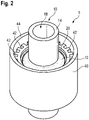
- the housing 40 may be provided with a plurality of recesses 42 in figure 2 you can see.
- the recesses can serve to save weight.
- the shrinkage pressure that the housing 40 exerts on the bearing shells 20 can be adjusted.
- the housing 40 can be equipped with in figure 2 be provided schematically indicated attachment portions 44, to each of which one end of a sealing bellows can be attached. The other end of the sealing bellows can be attached to the pin 14 .
- the ball joint 5 After the ball joint 5 has been removed from the injection mold, it can still be filled with grease or another lubricant. For this purpose, the grease is pressed into the joint via the lubricant grooves 28 that open out axially.
Landscapes
- Engineering & Computer Science (AREA)
- General Engineering & Computer Science (AREA)
- Mechanical Engineering (AREA)
- Chemical & Material Sciences (AREA)
- Oil, Petroleum & Natural Gas (AREA)
- Physics & Mathematics (AREA)
- Geometry (AREA)
- Pivots And Pivotal Connections (AREA)
Description
- Die Erfindung betrifft ein Kugelgelenk, das einen Kugelzapfen aufweist, der mittels zweier Lagerschalen innerhalb eines Gehäuses aufgenommen ist.
- Kugelgelenke sind in den verschiedensten Ausgestaltungen bekannt. Bei Kugelgelenken, die für Fahrwerksteile eines Kraftfahrzeugs vorgesehen sind, sind die übliche Anforderungen, dass der Kugelzapfen mit hohen Auszugskräften im Gehäuse aufgenommen ist, dass ein präzise definiertes Reibmoment zwischen Kugelzapfen und Lagerschale wirkt und dass sich ein geringer Verschleiß ergibt.
- Aus der
EP 2 284 408 A1 ist ein Kugelgelenk bekannt, bei dem die beiden Lagerschalen innerhalb eines Metallgehäuses angeordnet und dann mit Kunststoff umspritzt werden. Das Gehäuse ist innenseitig mit einer Rändelung versehen, so dass der Kunststoff mechanisch innerhalb des Gehäuses gehalten ist. - Die
EP 2 465 713 A1 offenbart ein Kugelgelenk mit einem zweiteiligen Lager, in dem ein Kugelzapfen gelagert ist und das von einem Gehäuse umspritzt ist, wobei die Lagerschalen in einem gegenseitigen Kontaktbereich vollflächig am Kugelzapfen anliegen. - In der
US 2009/0152834 A1 ist ein Kugelgelenk mit einem Gehäuse beschrieben, das eine Lagerschale umschließt, in der ein Kugelzapfen aufgenommen ist, wobei in der Lagerschale mehrere Nuten und Öffnungen ausgelassen sind, um ein Schmierkanalsystem zu bilden. - Die Aufgabe der Erfindung besteht darin, ein Kugelgelenk zu schaffen, das sich durch bessere Leistungswerte auszeichnet und kostengünstig hergestellt werden kann.
- Zur Lösung dieser Aufgabe ist erfindungsgemäß ein Kugelgelenkt vorgesehen mit einem Kugelzapfen, der einen Kugelabschnitt aufweist, zwei Lagerschalen, die jeweils einen Umfangsrand haben und auf dem Kugelabschnitt so angeordnet sind, dass ihre Umfangsränder sich in einem Abstand größer 0 gegenüberliegen, und einem Gehäuse, das einstückig aus Kunststoff besteht, wobei die beiden Lagerschalen so mit dem das Gehäuse bildenden Kunststoff umspritzt sind, dass sie vom Gehäuse umschlossen sind und dass sie vom Gehäuse gegen den Kugelabschnitt beaufschlagt werden. Dieses Kugelgelenk weist geringe Herstellungskosten auf, da der Kunststoff, der die beiden Lagerschalen umschließt, als Gehäuse wirkt, das in direktem Kontakt mit den beiden Lagerschalen steht und die nötige Festigkeit und Stabilität aufweist. Es ist kein Außengehäuse erforderlich. Auch umgeht diese Konstruktion das im Stand der Technik auftretende Problem, dass der Kunststoff, der um die Lagerschalen herum gespritzt wird, beim Aushärten schwindet, was eine zuverlässige Verbindung mit dem eigentlichen Gehäuse erschwert. Das erfindungsgemäße Kugelgelenk hat weiterhin den Vorteil, dass die Schwindung des Kunststoffmaterials, mit dem die Lagerschalen umspritzt werden, zielgerichtet in einen Anpressdruck umgesetzt werden kann, mit dem die Lagerschalen gegen den Kugelabschnitt beaufschlagt werden, da die beiden Lagerschalen wegen des zwischen ihnen vorhandenen Spalts, der frei von Material etc. ist, in axialer Richtung relativ zum Kugelabschnitt verschiebbar sind. Im Stand der Technik stützen sich dagegen die Lagerschalen aneinander ab, so dass sie insgesamt stark verformt werden müssen, falls sie mit einer Vorspannkraft gegen den Kugelabschnitt gedrückt werden sollen.
- Gemäß einer Ausführungsform der Erfindung ist vorgesehen, dass die Lagerschalen wechselseitige Eingriffsabschnitte aufweisen, so dass sie in radialer Richtung und in Umfangsrichtung zentriert sind, jedoch in axialer Richtung relativ zueinander verschiebbar sind. Die Eingriffsabschnitte gewährleisten, dass die beiden Lagerschalen relativ zueinander auch dann zentriert bleiben, wenn sie in einer Spritzgussform angeordnet sind und flüssiger Kunststoff in die Spritzgussform eingedrückt wird.
- Die Eingriffsabschnitte sind in Umfangsrichtung unterbrochen ausgeführt.
- Besonders vorteilhaft ist, wenn die Eingriffsabschnitte in Umfangsrichtung betrachtet dicht aneinander anliegen. Hierdurch kann ohne zusätzliche Maßnahmen gewährleistet werden, dass das flüssige Kunststoffmaterial beim Umspritzen nicht in den Bereich zwischen den beiden Lagerschalen und/oder auf den Kugelabschnitt gelangen kann; dies wäre für die Funktionsweise des Kugelgelenks nachteilig.
- Vorzugsweise bilden die Eingriffsabschnitte zusammen einen nach außen vorstehenden Bund bilden, der vom Material des Gehäuses fest umschlossen ist. Der Bund hilft, die beiden Lagerschalen zuverlässig innerhalb des Kunststoff-Gehäuses zu verankern.
- Vorzugsweise verrasten die Eingriffsabschnitte der einen Lagerschale mit der anderen Lagerschale. Diese ermöglicht, die beiden Lagerschalen auf dem Kugelzapfen vorzumontieren, so dass sie mit diesem als eine Baugruppe in einer Spritzgussform angeordnet werden kann.
- Gemäß einer Ausgestaltung der Erfindung ist vorgesehen, dass die Lagerschalen auf ihrer Außenseite taschenförmige Vertiefungen aufweisen. Die taschenförmigen Vertiefungen führen zu einer zielgerichteten Verringerung der Wandstärke der Lagerschalen, so dass dort die Nachgiebigkeit der Lagerschalen in radialer Richtung und damit die Anpresskraft eingestellt werden kann, mit der die Lagerschalen gegen den Kugelabschnitt gedrückt werden.
- Vorzugsweise beträgt die Wandstärke der Lagerschalen am Boden der Vertiefungen weniger als 50% der Wandstärke der Lagerschalen zwischen benachbarten Vertiefungen, so dass die Elastizität der Lagerschalen im Bereich des Bodens der Taschen erheblich erhöht ist.
- Gemäß einer Ausgestaltung der Erfindung ist vorgesehen, dass die Lagerschalen mit Schmiermittelnuten versehen sind, die an den axialen Enden der Lagerschalen münden. Dies ermöglicht es, das Kugelgelenk nachträglich zu befetten, also nachdem das Gehäuse auf die Lagerschalen aufgespritzt wurde.
- Das Gehäuse kann mit Ausnehmungen versehen sein, die sich ausgehend von den axialen Stirnseiten zum Mitte hin erstrecken. Mit den Ausnehmungen kann die Steifigkeit des Gehäuses und damit die Vorspannung, die vom Gehäuse auf die Lagerschalen ausgeübt wird, zielgerichtet eingestellt werden. Außerdem führen die Ausnehmungen zu einer Gewichtseinsparung.
- Gemäß einer Ausgestaltung der Erfindung ist vorgesehen, dass das Gehäuse an den Lagerschalen anhaftet. Dies kann durch erzielt werden, dass die Lagerschalen mit Kunststoffmaterial umspritzt werden, dass sich auf einer geeigneten Temperatur befindet, so dass die Lagerschalen außenseitig geringfügig angeschmolzen werden. Außerdem wird für das Kunststoff-Gehäuse ein Material verwendet, das mit dem Material der Lagerschalen eine stoffschlüssige Verbindung eingehen kann. Beispielsweise wird für das Gehäuse dasselbe Material verwendet wie für die Lagerschalen.
- Die Erfindung wird nachfolgend anhand einer Ausführungsform beschrieben, die in den beigefügten Zeichnungen dargestellt ist. In diesen zeigen:
-
Figur 1 ein erfindungsgemäßes Kugelgelenk in einem Längsschnitt; -
Figur 2 das Kugelgelenk vonFigur 1 in einer perspektivischen Ansicht; -
Figur 3 in einem Schnitt schematische eine Lagerschale des Kugelgelenks vonFigur 1 , wobei die Lagerschale auf ihrer Außenseite mit taschenförmigen Vertiefungen versehen ist ; -
Figur 4 die Lagerschale vonFigur 3 in einer perspektivischen Ansicht; -
Figur 5 in einem Schnitt schematisch eine Lagerschale des Kugelgelenks vonFigur 1 , wobei die Lagerschale auf ihrer Innenseite mit Schmiermittelnuten versehen ist; -
Figur 6 die Lagerschale vonFigur 5 in einer perspektivischen Ansicht, -
Figur 7 in einer perspektivischen Ansicht einen Schritt bei der Vormontage des erfindungsgemäßen Kugelgelenks; -
Figur 8 in einer Schnittansicht eine vormontierte Baugruppe aus Kugelzapfen und Lagerschalen vor dem Umspritzen; und -
Figur 9 das Detail IX vonFigur 8 in vergrößertem Maßstab. - In den
Figuren 1 und ist ein Kugelgelenk 5 zu sehen, das als wesentliche Bauteile einen Kugelzapfen 10, zwei Lagerschalen 20 und ein Gehäuse 40 aufweist. - Der Kugelzapfen 10 weist einen Kugelabschnitt 12 auf, von dem ausgehend sich an entgegengesetzten Enden jeweils ein Zapfen 14 erstreckt. Die beiden Zapfen sind konzentrisch zu einer Mittelachse 16 angeordnet, die auch durch den Mittelpunkt des Kugelabschnittes 12 verläuft.
- Zur Vereinfachung der Erläuterung sei nachfolgend angenommen, dass die Mittelachse 16 sich durch die "Pole" der dem Kugelabschnitt 12 zugrundeliegenden Kugel erstreckt. Somit erstreckt sich die Außenfläche des Kugelabschnitts 12 bei der gezeigten Ausführungsform entlang des "Äquators" des Kugelabschnittes 12. Bis zu welchem "Breitengrad" sich die Außenfläche des Kugelabschnitts 12 erstreckt, hängt ab vom Durchmesser der Zapfen 14. Beim gezeigten Ausführungsbeispiel erstreckt sich die Außenfläche bis zu einem Niveau von etwa ± 40°.
- Grundsätzlich ist auch denkbar, dass nur ein Zapfen 14 vorhanden ist.
- Bei der gezeigten Ausführungsform ist der Kugelzapfen 10 hohl. Anders ausgedrückt: es gibt einen Hohlraum 18, der sich durch die beiden Zapfen 14 und den Kugelabschnitt 12 hindurch erstreckt.
- Der Kugelzapfen 10 besteht bei der gezeigten Ausführungsform aus Metall, insbesondere aus Stahl.
- Die beiden Lagerschalen 20 sind jeweils in Umfangsrichtung umlaufend ausgeführt. Sie weisen einen innenliegenden Umfangsrand 22 und einen außenliegenden Umfangsrand 24 auf. Der innenliegende Umfangsrand 22 ist dabei auf der Seite des Äquators des Kugelabschnittes 12 angeordnet, während der außenliegende Umfangsrand 24 auf der Seite der Zapfen 14 angeordnet ist.
- Die Innenfläche jeder Lagerschale 20 hat die Form eines Kugelabschnitts.
- Die Lagerschalen bestehen aus Kunststoff, wobei eine Vielzahl von Thermoplasten und Duroplasten verwendet werden kann.
- Wie in den
Figuren 3 und 4 zu sehen ist, weist jede Lageschale 20 auf ihrer Außenseite, also der vom Kugelabschnitt 12 abgewandten Seite, mehrere taschenartige Vertiefungen 26 auf. - Jede Vertiefung 26 ist in sich abgeschlossen, weist also einen Umfangsrand 28 auf, der die Vertiefung 26 von der Außenseite der Lagerschale 20 abgrenzt.
- Die Vertiefungen 26 dienen dazu, lokal die Wandstärke der Lagerschalen 20 zu verringern. Im gezeigten Ausführungsbeispiel beträgt die Wandstärke s am Boden der Vertiefungen weniger als 50% der Wandstärke der Lagerschalen 20 im Bereich zwischen den Vertiefungen 26.
- Die Abmessungen der Vertiefungen können an die jeweiligen Anforderungen angepasst werden. Im gezeigten Ausführungsbeispiel beträgt die Höhe der Vertiefungen, also gemessen parallel zur Mittelachse 16, in der Größenordnung von 30 % der Höhe der entsprechenden Lagerschale.
- Der Abstand zwischen benachbarten Vertiefungen 26, gemessen in Umfangsrichtung, beträgt im gezeigten Ausführungsbeispiel etwa 50 % der Breite jeder Vertiefung 26.
- Wie in den
Figuren 5 und 6 zu sehen ist, weist jede Lagerschale 20 auf ihrer Innenfläche, also der Seite, die mit der Außenfläche des Kugelabschnittes 12 zusammenwirkt, mehrere Schmiermittelnuten 28 auf. Diese münden am außenliegenden Umfangsrand 24. - Beim gezeigten Ausführungsbeispiel erstrecken sich die Schmiermittelnuten 28 in der Richtung von Längengraden auf dem Kugelabschnitt. Es ist alternativ auch möglich, dass sich die Schmiermittelnuten mit einem von 0° verschiedenen Winkel schräg zu den Längengraden erstrecken.
- Die taschenartigen Vertiefungen 26 und die Schmiermittelnuten 28 sind hier an unterschiedlichen Lagerschalen 20 gezeigt. In der Praxis kann das Kugelgelenk 5 entweder die taschenartigen Vertiefungen 26 aufweisen oder die Schmiermittelnuten 28 oder sowohl die taschenartigen Vertiefungen 26 als auch die Schmiermittelnuten 28.
- Zwischen den beiden Lagerschalen 20 befindet sich, wenn sie auf dem Kugelabschnitt 12 vormontiert sind, ein kleiner Spalt 30. Anders ausgedrückt: die beiden inneren Umfangsränder 22 der Lagerschalen 20 liegen einander mit einem Abstand gegenüber, der gleich der Breite des Spalts 30 ist. Daher verläuft der Spalt entlang des Äquators des Kugelabschnittes 12 (unter der Annahme, dass die beiden Lagerschalen exakt auf dem Kugelabschnitt 12 zentriert angeordnet sind).
- Die inneren Umfangsränder 22 der Lagerschalen sind wechselseitig mit Eingriffsabschnitten 32, 34 versehen. "Wechselseitig" bedeutet dabei, dass die an einer Lagerschale 20 angeordneten Eingriffsabschnitte 32 mit den Eingriffsabschnitten 34 zusammenwirken, die an der anderen Lagerschale 20 vorgesehen sind.
- Insbesondere ist ein Eingriffsabschnitt 32 einer Lagerschale 20 zwischen zwei benachbarten Eingriffsabschnitten 34 der anderen Lagerschale 20 angeordnet.
- Ein Beispiel von wechselseitig angeordneten Eingriffsabschnitten 32, 34 ist in den
Figuren 5 und 6 gezeigt. Jeder der Lagerschalen 20 ist mit schmalen, in axialer Richtung vorstehenden Stegen 32 versehen, die in korrespondierende Schlitze 34 der anderen Lagerschale 20 eingreifen. - Die miteinander zusammenwirkenden Eingriffsabschnitte sorgen für einen Formschluss zwischen den beiden Lagerschalen 20 in Umfangsrichtung und zentrieren sie relativ zueinander. Gleichzeitig ermöglichen sie, dass die beiden Lagerschalen in axialer Richtung relativ zueinander verschoben werden können.
- In
Figur 7 ist eine weitere Ausgestaltung der Eingriffsabschnitte 32, 34 gezeigt. Der Unterschied zur in denFiguren 5 und 6 gezeigten Ausgestaltung besteht darin, dass die Eingriffsabschnitte 32, 34 als außenliegende Schürzen ausgestaltet sind, die radial außerhalb der einander gegenüberliegenden inneren Umfangsränder 22 angeordnet sind und über diese in axialer Richtung zur gegenüberliegenden Lageschale 20 hin vorstehen. - Weiterhin sind die Eingriffsabschnitte 32 der einen Lagerschale 20 in Umfangsrichtung so breit wie die Eingriffsabschnitte 34 der anderen Lagerschale 20. Somit liegt eine Schürze 32 der einen Lagerschale zwischen zwei benachbarten Schürzen 34 der anderen Lagerschale.
- Die Eingriffsabschnitte 32, 34 sind mit einer Übergangspassung oder einer Spielpassung mit sehr kleinem Spiel dimensioniert. Daher schließen die Schürzen 32, 34 den Spalt 30 zwischen den Lagerschalen 20 nach außen ab, während die beiden Lagerschalen 20 dennoch in axialer Richtung relativ zueinander verschiebbar sind.
- Die Schürzen 32, 34 sind vorzugsweise an ihrem vorderen Rand mit einer kleinen Rastkante versehen, die mit dem inneren Umfangsrand 22 der anderen Lagerschale zusammenwirken kann, so dass die beiden Lagerschalen aneinander vormontiert werden können.
- Um das Kugelgelenk 5 herzustellen, werden in einem ersten Schritt zwei Lagerschalen 20 auf dem Kugelabschnitt 12 vormontiert. Hierzu werden sie von entgegengesetzten Richtungen über die Zapfen 14 geschoben, bis sie auf dem Kugelabschnitt 12 angeordnet sind. Dabei rasten die Schürzen 32, 34 am inneren Umfangsrand 22 der jeweils anderen Lagerschale 20 ein, so dass die beiden Lagerschalen unverlierbar auf dem Kugelzapfen 10 vormontiert sind.
- Falls gewünscht, können die Lagerschalen 20 und/oder der Kugelabschnitt 12 gefettet werden, bevor die Lagerschalen 20 montiert werden.
- Die so vormontierte Baugruppe wird in eine Spritzgussform eingelegt, und die beiden Lagerschalen 20 werden mit einem Kunststoff umspritzt, der das Gehäuse 40 bildet. An den axialen Enden der beiden Lagerschalen 20 dichtet die Spritzgussform ab, so dass dort kein Material auf den Kugelzapfen 10 gelangen kann.
- Zwischen den beiden Lagerschalen 20 dichten die Eingriffsabschnitte 32, 34 so ab, dass kein Material zwischen die beiden Lagerschalen 20 gelangen kann, also der Spalt 30 freibleibt.
- Beim Aushärten des Gehäuses 40 sorgt die Schwindung des Kunststoffmaterials dafür, dass die beiden Lagerschalen 20 in axialer Richtung zusammengeschoben werden. Da der Spalt 30 zwischen den beiden Lagerschalen 20 vorhanden ist, wird der Schwindungsdruck in eine Vorspannung umgesetzt, mit der die Innenfläche der Lagerschalen 20 gegen den Kugelabschnitt 12 des Kugelzapfens gedrückt wird.
- Der Schwindungsdruck, den das Gehäuse 40 auf die Lagerschalen 20 ausübt, sorgt auch dafür, dass die Lagerschalen in radialer Richtung gegen den Kugelabschnitt 12 gedrückt werden. Die sich damit einstellende Vorspannung zwischen den Lagerschalen 20 und dem Kugelabschnitt 12 kann noch durch die gewählten Dimensionen der taschenartigen Vertiefungen 26 eingestellt werden. Je geringer die verbleibende Wandstärke am Boden der taschenartigen Vertiefungen 26, desto geringer ist die Steifigkeit der Lagerschalen 20 in diesen Bereichen und desto größer ist die Vorspannung, mit der die Lagerschalen 20 in diesen Bereichen gegen den Kugelabschnitt 12 gedrückt wird.
- Die Spritzgussform ist so dimensioniert, dass das Gehäuse 40 als solches eigenstabil ist und die Lagerschalen 20 so fest umschließt, dass alle im Betrieb später auftretenden Belastungen vom Gehäuse 40 aufgenommen werden können.
- Bei geeigneter Temperaturführung beim Spritzgießen und bei geeigneter Auswahl der Materialien für die Lagerschalen 20 und das Gehäuse 40 verbindet sich das Gehäuse mit den Lagerschalen 20. Ungeachtet einer eventuellen stoffschlüssigen Verbindung zwischen den Lagerschalen 20 und dem Gehäuse 40 umschließt das Gehäuse 40 die Lagerschalen 20 formschlüssig. So wird der Bund, der von den Eingriffsabschnitten 32, 34 gebildet wird, vom Gehäuse 40 umgriffen. Außerdem greift das Gehäuse 40 in die taschenartigen Vertiefungen 26 ein.
- Das Gehäuse 40 kann mit mehreren Ausnehmungen 42 versehen sein, die in
Figur 2 zu sehen sind. Die Ausnehmungen können der Gewichtsersparnis dienen. Außerdem kann durch Auswahl der Breite, der Tiefe, bis zu der sich die Ausnehmungen 42 in axialer Richtung ins Gehäuse hinein erstrecken, und der Position der Ausnehmungen 42 der Schwindungsdruck eingestellt werden, den das Gehäuse 40 auf die Lagerschalen 20 ausübt. - Das Gehäuse 40 kann mit in
Figur 2 schematisch angedeuteten Befestigungsabschnitte 44 versehen sein, an denen jeweils ein Ende eines Dichtungsbalgs angebracht werden kann. Das andere Ende des Dichtungsbalgs kann am Zapfen 14 angebracht sein. - Nachdem das Kugelgelenk 5 aus der Spritzgussform entnommen wurde, kann es noch mit Fett oder einem anderen Schmiermittel befüllt werden. Hierfür wird das Fett über die axial mündenden Schmiermittelnuten 28 in das Gelenk eingedrückt.
Claims (10)
- Kugelgelenk (5) mit einem Kugelzapfen (10), der einen Kugelabschnitt (12) aufweist, zwei Lagerschalen (20), die jeweils einen Umfangsrand (22) haben und auf dem Kugelabschnitt (12) so angeordnet sind, dass ihre Umfangsränder (22) sich in einem Abstand größer 0 gegenüberliegen, und einem Gehäuse (40), das einstückig aus Kunststoff besteht, wobei die beiden Lagerschalen (20) so mit dem das Gehäuse (40) bildenden Kunststoff umspritzt sind, dass sie vom Gehäuse (40) umschlossen sind und dass sie vom Gehäuse (40) gegen den Kugelabschnitt (12) beaufschlagt werden.
- Kugelgelenk nach Anspruch 1, dadurch gekennzeichnet, dass die Lagerschalen (20) wechselseitige Eingriffsabschnitte (32, 34) aufweisen, so dass sie in radialer Richtung und in Umfangsrichtung zentriert sind, jedoch in axialer Richtung relativ zueinander verschiebbar sind.
- Kugelgelenk nach Anspruch 2, dadurch gekennzeichnet, dass die Eingriffsabschnitte (32, 34) in Umfangsrichtung betrachtet dicht aneinander anliegen.
- Kugelgelenk nach Anspruch 3, dadurch gekennzeichnet, dass die Eingriffsabschnitte (32, 34) zusammen einen nach außen vorstehenden Bund bilden, der vom Material des Gehäuses (40) fest umschlossen ist.
- Kugelgelenk nach einem der Ansprüche 2 bis 4, dadurch gekennzeichnet, dass die Eingriffsabschnitte (32, 34) der einen Lagerschale (20) mit der anderen Lagerschale (20) verrasten.
- Kugelgelenk nach einem der vorhergehenden Ansprüche, dadurch gekennzeichnet, dass die Lagerschalen (20) auf ihrer Außenseite taschenförmige Vertiefungen (28) aufweisen.
- Kugelgelenk nach Anspruch 6, dadurch gekennzeichnet, dass die Wandstärke der Lagerschalen (20) am Boden der Vertiefungen (28) weniger als 50% der Wandstärke der Lagerschalen (20) zwischen benachbarten Vertiefungen (28) beträgt.
- Kugelgelenk nach einem der vorhergehenden Ansprüche, dadurch gekennzeichnet, dass die Lagerschalen (20) mit Schmiermittelnuten (26) versehen sind, die an den axialen Enden der Lagerschalen (20) münden.
- Kugelgelenk nach einem der vorhergehenden Ansprüche, dadurch gekennzeichnet, dass das Gehäuse (40) mit Ausnehmungen (42) versehen ist, die sich ausgehend von den axialen Stirnseiten zum Mitte hin erstrecken.
- Kugelgelenk nach einem der vorhergehenden Ansprüche, dadurch gekennzeichnet, dass das Gehäuse (40) an den Lagerschalen (20) anhaftet.
Applications Claiming Priority (2)
| Application Number | Priority Date | Filing Date | Title |
|---|---|---|---|
| DE102018103780.5A DE102018103780A1 (de) | 2018-02-20 | 2018-02-20 | Kugelgelenk, insbesondere für Fahrwerksteile eines Kraftfahrzeugs |
| PCT/EP2019/054221 WO2019162330A1 (de) | 2018-02-20 | 2019-02-20 | Kugelgelenk, insbesondere für fahrwerksteile eines kraftfahrzeugs |
Publications (2)
| Publication Number | Publication Date |
|---|---|
| EP3755909A1 EP3755909A1 (de) | 2020-12-30 |
| EP3755909B1 true EP3755909B1 (de) | 2022-04-20 |
Family
ID=65657435
Family Applications (1)
| Application Number | Title | Priority Date | Filing Date |
|---|---|---|---|
| EP19708793.5A Active EP3755909B1 (de) | 2018-02-20 | 2019-02-20 | Kugelgelenk, insbesondere für fahrwerksteile eines kraftfahrzeugs |
Country Status (5)
| Country | Link |
|---|---|
| US (1) | US11339824B2 (de) |
| EP (1) | EP3755909B1 (de) |
| CN (1) | CN112119227A (de) |
| DE (1) | DE102018103780A1 (de) |
| WO (1) | WO2019162330A1 (de) |
Families Citing this family (2)
| Publication number | Priority date | Publication date | Assignee | Title |
|---|---|---|---|---|
| US11795994B1 (en) * | 2019-12-16 | 2023-10-24 | Zhejiang Ruitai Suspension System Technology Ltd | Socket assembly with antirotation spring washer |
| CN115342123A (zh) * | 2022-08-08 | 2022-11-15 | 内蒙古北方重型汽车股份有限公司 | 矿用自卸车一体式鼻锥内轴承及其加工方法和安装方法 |
Family Cites Families (30)
| Publication number | Priority date | Publication date | Assignee | Title |
|---|---|---|---|---|
| GB1249089A (en) | 1969-10-21 | 1971-10-06 | Viktor Langen | Improvements in ball and socket joints |
| JPS5328576B2 (de) * | 1973-07-02 | 1978-08-15 | ||
| GB2052620A (en) * | 1979-06-20 | 1981-01-28 | Gkn Automotive Fasteners Ltd | Ball and socket joints |
| DE3326960C2 (de) * | 1983-07-27 | 1991-08-01 | TRW Ehrenreich GmbH & Co KG, 4000 Düsseldorf | Kugelgelenk |
| US4678350A (en) * | 1986-06-02 | 1987-07-07 | Statz Robert G | Bearing assembly |
| DE3702277A1 (de) * | 1987-01-27 | 1988-08-04 | Trw Ehrenreich Gmbh | Kugelgelenk |
| DE3933163A1 (de) * | 1988-10-27 | 1990-05-03 | Toyoda Gosei Kk | Zylindrische daempfungsbuchse |
| DE4109697C1 (de) * | 1991-03-23 | 1992-06-25 | Trw Ehrenreich Gmbh & Co Kg, 4000 Duesseldorf, De | |
| US5931597A (en) * | 1997-10-16 | 1999-08-03 | Trw Inc. | Ball joint |
| US6350060B1 (en) * | 2000-03-02 | 2002-02-26 | Raytheon Company | Dual load path spherical bearing and a method of coupling along a dual load path |
| DE10023602C2 (de) * | 2000-05-15 | 2002-06-27 | Zf Lemfoerder Metallwaren Ag | Kugelhülsengelenk |
| DE10028984C2 (de) * | 2000-06-16 | 2002-09-26 | Zf Lemfoerder Metallwaren Ag | Lagerschale für Kugelgelenke oder Kugelhülsengelenke |
| DE10150189A1 (de) * | 2001-10-12 | 2003-04-17 | Zf Lemfoerder Metallwaren Ag | Schwingungsgedämpfes Gummilager |
| US6776552B2 (en) * | 2002-04-26 | 2004-08-17 | The Timken Company | Ball joint with spherical rollers |
| DE10362009B4 (de) * | 2003-09-09 | 2009-04-09 | ZF Lemförder GmbH | Kugelgelenk |
| DE10361289B4 (de) * | 2003-12-24 | 2006-05-24 | Daimlerchrysler Ag | Kugelgelenk |
| US7543992B2 (en) * | 2005-04-28 | 2009-06-09 | General Electric Company | High temperature rod end bearings |
| US7438493B2 (en) * | 2005-11-03 | 2008-10-21 | ZF Lemförder Metallwaren AG | Cross axis ball and socket joint with sealing ring for cross axis sleeve ends |
| US20080304902A1 (en) * | 2006-11-01 | 2008-12-11 | Tomasz Buchner | Ball joint |
| DE102007016713B4 (de) * | 2007-04-04 | 2011-07-14 | Saint-Gobain Performance Plastics Pampus GmbH, 47877 | Gelenklager |
| DE102007060287B4 (de) * | 2007-12-12 | 2022-09-22 | Zf Friedrichshafen Ag | Gelenkeinheit |
| US8171600B2 (en) * | 2009-05-19 | 2012-05-08 | Gyrobag, Llc | Omni-directional handle |
| KR101225742B1 (ko) | 2009-08-10 | 2013-02-12 | 주식회사 일진 | 자동차용 볼 조인트 어셈블리 |
| WO2011019108A1 (ko) * | 2009-08-10 | 2011-02-17 | 주식회사 일진 | 볼조인트 구조 및 이의 제조방법 |
| KR101312710B1 (ko) * | 2010-06-14 | 2013-10-01 | 주식회사 일진 | 차량용 샤시 부품 연결용 단일축 댐핑 조인트 |
| DE102011076091A1 (de) * | 2011-05-19 | 2012-11-22 | Schaeffler Technologies AG & Co. KG | Gelenklager zur Aufnahme von Radial- und Axialkräften |
| DE202011109569U1 (de) | 2011-12-23 | 2012-03-07 | Brose Fahrzeugteile Gmbh & Co. Kg, Hallstadt | Spindelantrieb für ein Verstellelement eines Kraftfahrzeugs |
| BR102013008312A8 (pt) * | 2013-04-05 | 2017-10-10 | Tigre S/A Tubos E Conexoes | Registro esfera |
| DE102015221046A1 (de) * | 2015-10-28 | 2017-05-04 | Zf Friedrichshafen Ag | Radialkugelgelenk für ein Fahrzeug |
| DE102016203470B4 (de) * | 2016-03-03 | 2018-10-25 | Zf Friedrichshafen Ag | Verfahren zum Verbinden eines Kugelgelenks mit einem Gegenstück |
-
2018
- 2018-02-20 DE DE102018103780.5A patent/DE102018103780A1/de not_active Withdrawn
-
2019
- 2019-02-20 CN CN201980014311.4A patent/CN112119227A/zh active Pending
- 2019-02-20 EP EP19708793.5A patent/EP3755909B1/de active Active
- 2019-02-20 WO PCT/EP2019/054221 patent/WO2019162330A1/de not_active Ceased
- 2019-02-22 US US16/971,445 patent/US11339824B2/en active Active
Also Published As
| Publication number | Publication date |
|---|---|
| CN112119227A (zh) | 2020-12-22 |
| EP3755909A1 (de) | 2020-12-30 |
| US11339824B2 (en) | 2022-05-24 |
| DE102018103780A1 (de) | 2019-08-22 |
| US20210131484A1 (en) | 2021-05-06 |
| WO2019162330A1 (de) | 2019-08-29 |
Similar Documents
| Publication | Publication Date | Title |
|---|---|---|
| DE3700057C2 (de) | ||
| DE102012014318B4 (de) | Federfunktionsbauteil für ein hydroelastisches Lager und hydroelastisches Lager | |
| EP0653573B1 (de) | Kugelgelenk | |
| EP2239476B1 (de) | Gegenbahngelenk | |
| EP2976545B1 (de) | Verfahren zum herstellen eines lagers und lager | |
| DE3527870A1 (de) | Nachgiebige kugelgelenkanordnung und verfahren zu ihrer herstellung | |
| EP3548757B1 (de) | Kugelschale für ein kugelgelenk | |
| DE112008002621T5 (de) | Rollvorrichtung | |
| EP1811210A1 (de) | Radialdichtung | |
| DE29722507U1 (de) | Kugelschale für ein Kugelgelenk und Kugelgelenk mit einer solchen Kugelschale | |
| DE102021109281B4 (de) | Wälzlager mit einem elektrisch isolierenden Isoliermaterial | |
| EP3755909B1 (de) | Kugelgelenk, insbesondere für fahrwerksteile eines kraftfahrzeugs | |
| EP1132642B1 (de) | Gummilager | |
| EP2791523B1 (de) | Kugellagerkäfig, sowie hiermit versehenes rillenkugellager | |
| WO2021069008A1 (de) | Zweiteiliger lagerkäfig sowie wälzlager mit einem solchen lagerkäfig | |
| DE10355363A1 (de) | Lageranordnung | |
| DE102010042849B4 (de) | Lagerkäfig und Verfahren zur Herstellung desselben | |
| DE102018215172B4 (de) | Kugelgelenk für ein Fahrzeug sowie Verschlusselement für ein solches Kugelgelenk | |
| EP1138968A1 (de) | Labyrinthdichtung für eine Gelenkkreuzwelle | |
| DE3639963C2 (de) | ||
| WO2016206879A1 (de) | Axialkugelgelenk | |
| DE19904031A1 (de) | Anschlußlager, insbesondere für ein Kolben-Zylinderaggregat | |
| DE19951388A1 (de) | Toleranzring | |
| DE102010026855A1 (de) | Ausrücklageranordnung, insbesondere für eine hydraulische Kupplung | |
| DE102018127390B4 (de) | Verfahren zur Herstellung eines Kunststoff-Koppelelements mit einem Kugelgelenk sowie derartiges Kunststoff-Koppelelement |
Legal Events
| Date | Code | Title | Description |
|---|---|---|---|
| STAA | Information on the status of an ep patent application or granted ep patent |
Free format text: STATUS: UNKNOWN |
|
| STAA | Information on the status of an ep patent application or granted ep patent |
Free format text: STATUS: THE INTERNATIONAL PUBLICATION HAS BEEN MADE |
|
| PUAI | Public reference made under article 153(3) epc to a published international application that has entered the european phase |
Free format text: ORIGINAL CODE: 0009012 |
|
| STAA | Information on the status of an ep patent application or granted ep patent |
Free format text: STATUS: REQUEST FOR EXAMINATION WAS MADE |
|
| 17P | Request for examination filed |
Effective date: 20200814 |
|
| AK | Designated contracting states |
Kind code of ref document: A1 Designated state(s): AL AT BE BG CH CY CZ DE DK EE ES FI FR GB GR HR HU IE IS IT LI LT LU LV MC MK MT NL NO PL PT RO RS SE SI SK SM TR |
|
| AX | Request for extension of the european patent |
Extension state: BA ME |
|
| DAV | Request for validation of the european patent (deleted) | ||
| DAX | Request for extension of the european patent (deleted) | ||
| GRAP | Despatch of communication of intention to grant a patent |
Free format text: ORIGINAL CODE: EPIDOSNIGR1 |
|
| STAA | Information on the status of an ep patent application or granted ep patent |
Free format text: STATUS: GRANT OF PATENT IS INTENDED |
|
| INTG | Intention to grant announced |
Effective date: 20211104 |
|
| GRAS | Grant fee paid |
Free format text: ORIGINAL CODE: EPIDOSNIGR3 |
|
| GRAA | (expected) grant |
Free format text: ORIGINAL CODE: 0009210 |
|
| STAA | Information on the status of an ep patent application or granted ep patent |
Free format text: STATUS: THE PATENT HAS BEEN GRANTED |
|
| AK | Designated contracting states |
Kind code of ref document: B1 Designated state(s): AL AT BE BG CH CY CZ DE DK EE ES FI FR GB GR HR HU IE IS IT LI LT LU LV MC MK MT NL NO PL PT RO RS SE SI SK SM TR |
|
| REG | Reference to a national code |
Ref country code: GB Ref legal event code: FG4D Free format text: NOT ENGLISH |
|
| REG | Reference to a national code |
Ref country code: CH Ref legal event code: EP |
|
| REG | Reference to a national code |
Ref country code: IE Ref legal event code: FG4D Free format text: LANGUAGE OF EP DOCUMENT: GERMAN |
|
| REG | Reference to a national code |
Ref country code: DE Ref legal event code: R096 Ref document number: 502019004122 Country of ref document: DE |
|
| REG | Reference to a national code |
Ref country code: AT Ref legal event code: REF Ref document number: 1485362 Country of ref document: AT Kind code of ref document: T Effective date: 20220515 |
|
| REG | Reference to a national code |
Ref country code: LT Ref legal event code: MG9D |
|
| REG | Reference to a national code |
Ref country code: NL Ref legal event code: MP Effective date: 20220420 |
|
| PG25 | Lapsed in a contracting state [announced via postgrant information from national office to epo] |
Ref country code: NL Free format text: LAPSE BECAUSE OF FAILURE TO SUBMIT A TRANSLATION OF THE DESCRIPTION OR TO PAY THE FEE WITHIN THE PRESCRIBED TIME-LIMIT Effective date: 20220420 |
|
| PG25 | Lapsed in a contracting state [announced via postgrant information from national office to epo] |
Ref country code: SE Free format text: LAPSE BECAUSE OF FAILURE TO SUBMIT A TRANSLATION OF THE DESCRIPTION OR TO PAY THE FEE WITHIN THE PRESCRIBED TIME-LIMIT Effective date: 20220420 Ref country code: PT Free format text: LAPSE BECAUSE OF FAILURE TO SUBMIT A TRANSLATION OF THE DESCRIPTION OR TO PAY THE FEE WITHIN THE PRESCRIBED TIME-LIMIT Effective date: 20220822 Ref country code: NO Free format text: LAPSE BECAUSE OF FAILURE TO SUBMIT A TRANSLATION OF THE DESCRIPTION OR TO PAY THE FEE WITHIN THE PRESCRIBED TIME-LIMIT Effective date: 20220720 Ref country code: LT Free format text: LAPSE BECAUSE OF FAILURE TO SUBMIT A TRANSLATION OF THE DESCRIPTION OR TO PAY THE FEE WITHIN THE PRESCRIBED TIME-LIMIT Effective date: 20220420 Ref country code: HR Free format text: LAPSE BECAUSE OF FAILURE TO SUBMIT A TRANSLATION OF THE DESCRIPTION OR TO PAY THE FEE WITHIN THE PRESCRIBED TIME-LIMIT Effective date: 20220420 Ref country code: GR Free format text: LAPSE BECAUSE OF FAILURE TO SUBMIT A TRANSLATION OF THE DESCRIPTION OR TO PAY THE FEE WITHIN THE PRESCRIBED TIME-LIMIT Effective date: 20220721 Ref country code: FI Free format text: LAPSE BECAUSE OF FAILURE TO SUBMIT A TRANSLATION OF THE DESCRIPTION OR TO PAY THE FEE WITHIN THE PRESCRIBED TIME-LIMIT Effective date: 20220420 Ref country code: ES Free format text: LAPSE BECAUSE OF FAILURE TO SUBMIT A TRANSLATION OF THE DESCRIPTION OR TO PAY THE FEE WITHIN THE PRESCRIBED TIME-LIMIT Effective date: 20220420 Ref country code: BG Free format text: LAPSE BECAUSE OF FAILURE TO SUBMIT A TRANSLATION OF THE DESCRIPTION OR TO PAY THE FEE WITHIN THE PRESCRIBED TIME-LIMIT Effective date: 20220720 |
|
| PG25 | Lapsed in a contracting state [announced via postgrant information from national office to epo] |
Ref country code: RS Free format text: LAPSE BECAUSE OF FAILURE TO SUBMIT A TRANSLATION OF THE DESCRIPTION OR TO PAY THE FEE WITHIN THE PRESCRIBED TIME-LIMIT Effective date: 20220420 Ref country code: PL Free format text: LAPSE BECAUSE OF FAILURE TO SUBMIT A TRANSLATION OF THE DESCRIPTION OR TO PAY THE FEE WITHIN THE PRESCRIBED TIME-LIMIT Effective date: 20220420 Ref country code: LV Free format text: LAPSE BECAUSE OF FAILURE TO SUBMIT A TRANSLATION OF THE DESCRIPTION OR TO PAY THE FEE WITHIN THE PRESCRIBED TIME-LIMIT Effective date: 20220420 Ref country code: IS Free format text: LAPSE BECAUSE OF FAILURE TO SUBMIT A TRANSLATION OF THE DESCRIPTION OR TO PAY THE FEE WITHIN THE PRESCRIBED TIME-LIMIT Effective date: 20220820 |
|
| REG | Reference to a national code |
Ref country code: DE Ref legal event code: R097 Ref document number: 502019004122 Country of ref document: DE |
|
| PG25 | Lapsed in a contracting state [announced via postgrant information from national office to epo] |
Ref country code: SM Free format text: LAPSE BECAUSE OF FAILURE TO SUBMIT A TRANSLATION OF THE DESCRIPTION OR TO PAY THE FEE WITHIN THE PRESCRIBED TIME-LIMIT Effective date: 20220420 Ref country code: SK Free format text: LAPSE BECAUSE OF FAILURE TO SUBMIT A TRANSLATION OF THE DESCRIPTION OR TO PAY THE FEE WITHIN THE PRESCRIBED TIME-LIMIT Effective date: 20220420 Ref country code: RO Free format text: LAPSE BECAUSE OF FAILURE TO SUBMIT A TRANSLATION OF THE DESCRIPTION OR TO PAY THE FEE WITHIN THE PRESCRIBED TIME-LIMIT Effective date: 20220420 Ref country code: EE Free format text: LAPSE BECAUSE OF FAILURE TO SUBMIT A TRANSLATION OF THE DESCRIPTION OR TO PAY THE FEE WITHIN THE PRESCRIBED TIME-LIMIT Effective date: 20220420 Ref country code: DK Free format text: LAPSE BECAUSE OF FAILURE TO SUBMIT A TRANSLATION OF THE DESCRIPTION OR TO PAY THE FEE WITHIN THE PRESCRIBED TIME-LIMIT Effective date: 20220420 Ref country code: CZ Free format text: LAPSE BECAUSE OF FAILURE TO SUBMIT A TRANSLATION OF THE DESCRIPTION OR TO PAY THE FEE WITHIN THE PRESCRIBED TIME-LIMIT Effective date: 20220420 |
|
| PLBE | No opposition filed within time limit |
Free format text: ORIGINAL CODE: 0009261 |
|
| STAA | Information on the status of an ep patent application or granted ep patent |
Free format text: STATUS: NO OPPOSITION FILED WITHIN TIME LIMIT |
|
| 26N | No opposition filed |
Effective date: 20230123 |
|
| PG25 | Lapsed in a contracting state [announced via postgrant information from national office to epo] |
Ref country code: AL Free format text: LAPSE BECAUSE OF FAILURE TO SUBMIT A TRANSLATION OF THE DESCRIPTION OR TO PAY THE FEE WITHIN THE PRESCRIBED TIME-LIMIT Effective date: 20220420 |
|
| PG25 | Lapsed in a contracting state [announced via postgrant information from national office to epo] |
Ref country code: SI Free format text: LAPSE BECAUSE OF FAILURE TO SUBMIT A TRANSLATION OF THE DESCRIPTION OR TO PAY THE FEE WITHIN THE PRESCRIBED TIME-LIMIT Effective date: 20220420 |
|
| PG25 | Lapsed in a contracting state [announced via postgrant information from national office to epo] |
Ref country code: MC Free format text: LAPSE BECAUSE OF FAILURE TO SUBMIT A TRANSLATION OF THE DESCRIPTION OR TO PAY THE FEE WITHIN THE PRESCRIBED TIME-LIMIT Effective date: 20220420 |
|
| REG | Reference to a national code |
Ref country code: CH Ref legal event code: PL |
|
| REG | Reference to a national code |
Ref country code: BE Ref legal event code: MM Effective date: 20230228 |
|
| PG25 | Lapsed in a contracting state [announced via postgrant information from national office to epo] |
Ref country code: LU Free format text: LAPSE BECAUSE OF NON-PAYMENT OF DUE FEES Effective date: 20230220 Ref country code: LI Free format text: LAPSE BECAUSE OF NON-PAYMENT OF DUE FEES Effective date: 20230228 Ref country code: CH Free format text: LAPSE BECAUSE OF NON-PAYMENT OF DUE FEES Effective date: 20230228 |
|
| REG | Reference to a national code |
Ref country code: IE Ref legal event code: MM4A |
|
| PG25 | Lapsed in a contracting state [announced via postgrant information from national office to epo] |
Ref country code: IT Free format text: LAPSE BECAUSE OF FAILURE TO SUBMIT A TRANSLATION OF THE DESCRIPTION OR TO PAY THE FEE WITHIN THE PRESCRIBED TIME-LIMIT Effective date: 20220420 Ref country code: IE Free format text: LAPSE BECAUSE OF NON-PAYMENT OF DUE FEES Effective date: 20230220 |
|
| PG25 | Lapsed in a contracting state [announced via postgrant information from national office to epo] |
Ref country code: BE Free format text: LAPSE BECAUSE OF NON-PAYMENT OF DUE FEES Effective date: 20230228 |
|
| PG25 | Lapsed in a contracting state [announced via postgrant information from national office to epo] |
Ref country code: BG Free format text: LAPSE BECAUSE OF FAILURE TO SUBMIT A TRANSLATION OF THE DESCRIPTION OR TO PAY THE FEE WITHIN THE PRESCRIBED TIME-LIMIT Effective date: 20220420 |
|
| PG25 | Lapsed in a contracting state [announced via postgrant information from national office to epo] |
Ref country code: BG Free format text: LAPSE BECAUSE OF FAILURE TO SUBMIT A TRANSLATION OF THE DESCRIPTION OR TO PAY THE FEE WITHIN THE PRESCRIBED TIME-LIMIT Effective date: 20220420 |
|
| REG | Reference to a national code |
Ref country code: AT Ref legal event code: MM01 Ref document number: 1485362 Country of ref document: AT Kind code of ref document: T Effective date: 20240220 |
|
| PG25 | Lapsed in a contracting state [announced via postgrant information from national office to epo] |
Ref country code: AT Free format text: LAPSE BECAUSE OF NON-PAYMENT OF DUE FEES Effective date: 20240220 |
|
| PG25 | Lapsed in a contracting state [announced via postgrant information from national office to epo] |
Ref country code: CY Free format text: LAPSE BECAUSE OF FAILURE TO SUBMIT A TRANSLATION OF THE DESCRIPTION OR TO PAY THE FEE WITHIN THE PRESCRIBED TIME-LIMIT; INVALID AB INITIO Effective date: 20190220 |
|
| PG25 | Lapsed in a contracting state [announced via postgrant information from national office to epo] |
Ref country code: HU Free format text: LAPSE BECAUSE OF FAILURE TO SUBMIT A TRANSLATION OF THE DESCRIPTION OR TO PAY THE FEE WITHIN THE PRESCRIBED TIME-LIMIT; INVALID AB INITIO Effective date: 20190220 |
|
| PG25 | Lapsed in a contracting state [announced via postgrant information from national office to epo] |
Ref country code: TR Free format text: LAPSE BECAUSE OF FAILURE TO SUBMIT A TRANSLATION OF THE DESCRIPTION OR TO PAY THE FEE WITHIN THE PRESCRIBED TIME-LIMIT Effective date: 20220420 |
|
| PGFP | Annual fee paid to national office [announced via postgrant information from national office to epo] |
Ref country code: GB Payment date: 20260220 Year of fee payment: 8 |
|
| PGFP | Annual fee paid to national office [announced via postgrant information from national office to epo] |
Ref country code: DE Payment date: 20260121 Year of fee payment: 8 |
|
| PGFP | Annual fee paid to national office [announced via postgrant information from national office to epo] |
Ref country code: AT Payment date: 20260410 Year of fee payment: 5 |
|
| PGFP | Annual fee paid to national office [announced via postgrant information from national office to epo] |
Ref country code: FR Payment date: 20260218 Year of fee payment: 8 |