EP3755840B1 - Refiner segment - Google Patents
Refiner segment Download PDFInfo
- Publication number
- EP3755840B1 EP3755840B1 EP19758005.3A EP19758005A EP3755840B1 EP 3755840 B1 EP3755840 B1 EP 3755840B1 EP 19758005 A EP19758005 A EP 19758005A EP 3755840 B1 EP3755840 B1 EP 3755840B1
- Authority
- EP
- European Patent Office
- Prior art keywords
- refiner
- refining
- segment
- bar
- disc
- Prior art date
- Legal status (The legal status is an assumption and is not a legal conclusion. Google has not performed a legal analysis and makes no representation as to the accuracy of the status listed.)
- Active
Links
Images


Classifications
-
- B—PERFORMING OPERATIONS; TRANSPORTING
- B02—CRUSHING, PULVERISING, OR DISINTEGRATING; PREPARATORY TREATMENT OF GRAIN FOR MILLING
- B02C—CRUSHING, PULVERISING, OR DISINTEGRATING IN GENERAL; MILLING GRAIN
- B02C7/00—Crushing or disintegrating by disc mills
- B02C7/11—Details
- B02C7/12—Shape or construction of discs
-
- D—TEXTILES; PAPER
- D21—PAPER-MAKING; PRODUCTION OF CELLULOSE
- D21D—TREATMENT OF THE MATERIALS BEFORE PASSING TO THE PAPER-MAKING MACHINE
- D21D1/00—Methods of beating or refining; Beaters of the Hollander type
- D21D1/20—Methods of refining
- D21D1/30—Disc mills
- D21D1/303—Double disc mills
-
- D—TEXTILES; PAPER
- D21—PAPER-MAKING; PRODUCTION OF CELLULOSE
- D21D—TREATMENT OF THE MATERIALS BEFORE PASSING TO THE PAPER-MAKING MACHINE
- D21D1/00—Methods of beating or refining; Beaters of the Hollander type
- D21D1/20—Methods of refining
- D21D1/30—Disc mills
- D21D1/306—Discs
Definitions
- the proposed technology generally relates to refiner segments for a refiner of lignocellulosic material. More specifically it relates to a refiner segment that is provided with refining bars arranged in different bar zones on the refiner segment surface. Embodiments herein also relates to a refiner rotor or a refiner stator comprising refining segments with refining bars arranged in different bar zones. Another embodiment of the proposed technology provides a refiner comprising at least one of a refiner rotor or a refiner stator provided with refiner segments having refining bars arranged in different bar zones on the refiner segment surface.
- a common refiner of lignocellulosic material usually comprises a rotor unit and a stator unit that are aligned along a pulp feeding axis facing each other. The refining of the material is performed in a bounded area between the rotor unit and the stator unit. During use of the refiner, material, e.g., pulp, is fed into an area arranged in between, and bounded by, the stator unit and a rotor unit.
- the rotor unit facing the stator unit may in particular versions be arranged on a rotatable shaft that can be rotated by means of an electrical motor.
- the purpose of the rotor unit which in the following will be simply referred to as a rotor, is to grind the pulp between a surface of the stator unit and a surface of the rotor.
- the rotor and/or stator are often provided with refining segments on their surfaces. The purpose of these refining segments is to improve the grinding action on the material.
- the refining segments are in turn often provided with additional structures to improve the refining action even further. These structures often comprises refining bars arranged on the surface of the rotor and/or the stator.
- the refining bars protrudes from the surface of the rotor disc/stator disc and faces the material flow. To ensure an efficient material flow in the area between the stator and rotor these refining bars must be provided in a fashion where they disturb the material flow as little as possible while they at the same time produces an efficient grinding of the material. It is a highly non-trivial challenge to fulfill both these criteria's.
- a refiner segment according to the preamble of claim 1 is disclosed in US 3149792 .
- the proposed technology aims to overcome at least some of the challenges associated with the design of refining segments for a refiner of e.g., lignocellulosic material.
- An additional object is to provide a refiner comprising such a rotor.
- a refiner segment according to the invention wherein the refiner disc is a rotor refiner disc.
- a refiner comprising a rotor refiner disc according to the second aspect.
- Embodiments of the proposed technology provides refiner segments together with corresponding rotor discs, stator discs and refiners that yield both an efficient material flow within an into the refiners refining area and an efficient refining action on lignocellulosic material such as e.g., wood.
- Fig.8 schematically shows an exemplary pulp refiner in a cross-sectional view.
- the arrangement is housed in a housing 30 that represents the outer casing of the refiner device together with all components of the device that is not essential for understanding the present invention.
- components not shown are an electrical motor for driving e.g. the rotation shaft, the feeding mechanism for the lignocellulosic material etc.
- Inside a second housing 31 a rotor 100* and a stator 20* is linearly aligned along a shaft.
- the rotor is attached to a rotation shaft 15 arranged on bearings 16.
- the rotation shaft 15 is connected to a motor, not shown, that rotates the shaft 15, and thus the rotor 10.
- the stator 20* facing the rotor 100* can be provided with a centrally located through hole 32 that extends between a feeding channel 14 for lignocellulosic material and a refining area 19.
- the rotor 100 can in certain embodiments be provided with a center plate 17 having a surface facing the incoming flow of lignocellulosic material.
- the surface of the center plate 17 can be provided with structures that will direct the lignocellulosic material outwards.
- the rotor 100* and/or the stator 20* also referred to as rotor (refiner) discs and stator (refiner) discs, respectively, are provided with refining segments to enable steering and grinding of the pulp. These grinding segments are often provided with protrusions on the surfaces intended to enhance the grinding action of the pulp.
- lignocellulosic material such as wood chips or prepared wood, e.g., pulp
- the material will pass through the hole 32 in the stator 20* and enter an area 19.
- the area 19 is essentially defined by the open area between the rotor 100* and the stator 20* and this area can be quite small during operation.
- the lignocellulosic material flowing into the area 19 will be incident on the center plate 17 on the rotor 100*.
- the center plate 17 acts to steer the lignocellulosic material out towards the refining segments on the rotor and/stator.
- FIG. 7 illustrates a cross-sectional side view of a rotor - stator arrangement housed in a housing 31 in a refiner as e.g., described above. Shown is a rotor 100* that is arranged to rotate around a rotation shaft. The rotor 100* is provided, on the surface facing the stator 20*, with a refining disc 100. The stator 20* is provided, on the surface facing the rotor 100*, with a refining disc 20.
- the refining discs 100, 20 may in certain versions of a refiner be referred to as a segment holders since one of the purposes of the refining discs 100, 20 is to carry refining segments.
- the refining discs of the rotor 100* and the stator 20* are provided with two different types of refining segments, a first type of refining segments 10, 10*, referred to as inlet segments, and a second type of refining segments 34, 34*, referred to as refining zone segments.
- these segments are sometimes referred to as center segments or c-segments 10, 10* and peripheral segments, or p-segments 34, 34*, respectively.
- the segments will be referred to as c-segments and p-segments but it should be noted that it actually relates to inlet segments and refining zone segments.
- segment 10, 10* There is a dual purpose with the first type of segment 10, 10*; it should provide an efficient grinding of lignocellulosic material but it should also enable an efficient material flow towards the p-segments 34, 34*.
- FIG. 7 Also illustrated in FIG. 7 is an inlet 32 for the lignocellulosic material subject to refining.
- the inlet 32 is arranged in the central area of the stator 20*.
- a center plate 17 Arranged in the center area of the refining disc 100 on the rotor side, opposing the inlet 32, is a center plate 17. The purpose of the center plate 17, which was described above with reference to FIG.
- the proposed technology relates to refining segments of the c-segment type, i.e., the type of refining segments that acts to ensure both an effective refining action and an effective steering of the material flow towards the refining segments of the p-segment type 34.
- the refining bars provided on the refiner segment aims to provide an efficient grinding action on the incoming material, a purpose that suggest that they should be given a prominent structure, i.e., they should protrude from the surface of the refiner segments.
- An efficient and even grinding or refining of the material requires however also that the incoming material is evenly distributed in the refining area.
- a general configuration of refining bars on a refining segment may however cause areas of varying material concentration.
- the refining bars should therefore be arranged on the refining segment in such a way that the incoming flow of lignocellulosic material gets evenly distributed and can be steered in a controlled manner towards the outer refining areas, e.g., towards the refining segments of p-segment type.
- the dual purposes of the refining bars make the design of a refining segment very tricky.
- One additional and substantial problem that negatively affects the material flow is the impact caused by water steam produced during the refining of the material. Since the material to be refined naturally comprises water, the substantial pressure in the housed rotor and stator arrangement will produce significant amounts of water steam.
- the proposed technology provides a refiner segment whose design has shown to provide a satisfactory refining action while at the same time ensuring an efficient and controlled flow of lignocellulosic material.
- the proposed technology provides in particular mechanisms that will reduce the negative impact the back-travelling steam have on the material flow. This is accomplished at least in part due to a particular configuration of refining bars that will enable the main material flow to occur on one refining disc side, e.g., on the rotor side of a rotor - stator arrangement while the other refining disc side, e.g., the stator side, can be occupied by back-travelling water steam. This will reduce the interaction between incoming wood chips and back-travelling water steam.
- the proposed technology provides a refiner segment 10 for a refiner 1 of lignocellulosic material.
- a refiner segment 10 that is integrated with a refining disc 100, or is adapted to be attached to a refining disc 100.
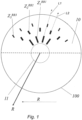
- the refining segment have a surface that comprises a number of refining bars Z i RBi that are arranged in an angular fashion around a common center area 11 in such a way that they form distinct bar zones Z i that encircles a common center on the refining disc 100.
- a particular bar zone Z i is defined as the area on the refining segment that comprises a corresponding set of refining bars Z i RBi .
- a number of refining bars Z 1 RB1 are provided in an innermost area, corresponding to bar zone Z 1
- a number of refining bars Z 2 RB2 are provided in an area, corresponding to bar zone Z 2 , that lies outside the innermost area.
- the directions are in relation to a radial direction having its origin in the center 11 of the refiner disc 100. This pattern is repeated so that a number of concentric bar zones are defined along the surface of the refining segment 100.
- Each bar zone comprises its own refining bars and refining bars belonging to neighboring bar zones may be spatially offset, i.e., arranged in such a way that there is a radial distance between refining bars belonging to neighboring bar zones. This is for example illustrated in FIG.1 .
- a particular feature of the proposed refining segment 10 is that refining bars Z i RBi that belong to different but neighboring bar zones Z and Z i + 1 are angularly offset. That is, they are arranged in such a fashion that the length direction of specific refining bars belonging to different but neighboring bar zones does not coincide.
- FIG.1 and FIG.2 where the length directions for refining bars belonging to bar zone Z 1 and Z 2 has been illustrated by means of dotted arrows, labelled L1 and L2, respectively.
- This angular offset between refining bars belonging to different but neighboring bar zones creates open bar areas that will allow material sub-flows to move over to the following, i.e., the neighboring, bar zone in a particular manner.
- This refining bar pattern has proved effective for achieving an even material flow over the refining segment towards the periphery, or towards the p-segments. It has in particular shown to be an efficient counter measure to the problem associated with water steam going backwards.
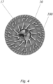
- the proposed refining segment ensures that the material flow along a particular refining segment is not forced towards the oppositely arranged refining disc, e.g., towards the stator side, if the refining segment is provided on the rotor side. Due to this fact the oppositely arranged refining disc will display a lot of open area which may be occupied by any water steam travelling backwards. Any residual amount of steam that might end up on e.g., the rotor side would still have space to move towards the center through the openings provided by the open areas between the refining bars. To appreciate this technical effect reference is made to FIG. 5a which illustrates a rotor disc comprising a refining segment according to the proposed technology. The schematic drawing illustrates both the path the material flow will take and the number of ways that the steam can travel. The refining bars that are angularly offset provides a smooth way for the material to follow while it also provides way for the movement of steam.
- the refining segment of the proposed technology provides a lot of open volume. This open volume can carry the material flow without forcing it towards the opposite side of the rotor-stator arrangement.
- the proposed refining segment also provide the highly desirable feature that it enables an even feed not only over the spatial disc geometry but also over time, and in particular a uniform flow over time despite the fact that the incoming material feed itself might be non-uniform.
- the proposed technology enables this feature by having a refining bar pattern that allows a material buffering effect.
- a particular embodiment of the proposed technology provides a refiner segment 10 wherein the angular offset between all neighboring bar zones Z i are in the same angular direction, the angular direction being the direction opposite to the intended rotational direction of the refiner segment 10.
- This embodiment provides an improved material flow since at least some of the refining bars belonging to different but neighboring bar zones can cooperate to obtain a uniform flow both spatially and over time. This embodiment is illustrated schematically in FIG. 5A .
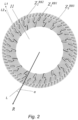
- FIG.2 Another embodiment of the proposed technology provides a refiner segment 10, wherein the refining bars of a particular bar zone are distributed angularly in a band of essentially equidistantly spaced refining bars Z i RBi that encircles the center 11 of the refiner disc 100.
- This embodiment is schematically illustrated in, for example, FIG.2 . It can be seen in FIG.2 how refining bars belonging to the same bar zone are arranged equidistant to each other in an angular pattern. Since they form part of the same band they are also arranged more or less equidistantly from a center of the disc.
- This particular embodiment ensures a symmetric configuration of refining bars which in turn has shown to lead to an even material flow.
- the shape of the refining bar pattern can be adjusted to improve the material feeding for different radii.
- FIGs 3a-3c illustrates a refining segment with three different bar zones
- the innermost bar zone is provided a number of refining bars.
- the number of refining bars are higher. This pattern may than be repeated for each additional bar zone.
- Still another particular embodiment of the proposed technology provides a refiner segment 10, wherein the number of equidistantly spaced refining bars Z i RBi increases from the lowest number in the innermost bar zone Z 1 , with regard to the center 11 of the refiner disc 100, to the highest number in the outermost bar zone Z N adjacent the periphery of the refiner segment 10.
- the number of refining bars provided in the bar zones are doubled for each bar zone going outwards towards the periphery. If the innermost bar zone Z 1 is provided with a number X of refining bars, the zone Z 2 that is adjacent to the zone Z 1 is provide with 2X bars and so on.
- the proposed technology provides a refiner segment 10, wherein refining bars Z i RBi belonging to different but neighboring bar zones are arranged in such a way that a tangential direction of a particular refining bar Z k RBk belonging to a bar zone Z i , points in a direction towards the mid-point between two refining bars Z k + 1 RBk + 1 belonging to a neighboring bar zone Z i , Z i + 1 .
- FIG.3b provides an illustration of this particular embodiment.
- the dotted lines illustrates the tangential direction of a refining bar.
- the tangential direction will coincide with the length direction of the refining bar while the tangential direction for a curved refining bar essentially follows the slope of the curvature of the refining bars.
- FIG.3c where the dotted lines illustrates the tangential direction for slightly curved refining bars.
- the embodiments where refining bars belonging to different bar zones or bands are arranged based on the tangential direction of refining bars belonging to the inner bar zone or band ensures an efficient material flow since it provides a lot of open area that can carry the material flow.
- a specific embodiment of the proposed technology provides a refiner segment 10, wherein the refining bars are provided with geometrical shapes such as straight edged bars, rounded bars, conical bars, arrow-shaped bars with or without chamfers, etc.
- the proposed technology provides a refiner segment 10, wherein at least a subset of the refining bars Z i RBi belonging to a particular bar zone Z; have a geometrical shape that is distinct from the geometrical shape of refining bars Z k RBk belonging to other bar zones Z k .
- Another embodiment of the proposed technology provides a refiner segment 10, wherein the length of refining bars belonging to different bar zones decreases from a largest length for refining bars Z 1 RB1 belonging to the innermost bar zone Z 1 , with regard to the center 11 of the refining disc 100, to the smallest length for refining bars Z N RBN belonging to the outermost bar zone Z N adjacent the periphery of the refiner segment 10.
- the open volume may decrease. This may be compensated by a stepwise shortening of refining bars, i.e., the farther out from the center of the refining segment or refining disc the refining bars are provided, the shorter they are, this is schematically illustrated in e.g., FIG. 3b .
- a refiner segment 10 wherein at least a subset of the refining bars Z i RBi is provided on the surface of the refiner segment 10 in such a way that an angle ⁇ is formed between the radial direction of the refiner segment 10 and the length direction of a refining bar Z i RBi .
- the lower part of FIG.2 illustrates such an embodiment.
- the length direction of a particular refining bar is denoted L and it can be seen how this length direction forms an angle ⁇ with the radial direction.
- a particular version of the above mentioned embodiment provides a refiner segment 10, wherein the angle ⁇ formed between the radial direction of the refiner segment 10 and the length direction of a refining bar Z i RBi defines the bar feeding angle and wherein the angle ⁇ takes value in the interval 0° ⁇ ⁇ ⁇ 60°.
- Another particular embodiment of the proposed technology provides a refiner segment 10, wherein refining bars Z i RBi belonging to different bar zones Z i have different widths, and wherein the widths decreases from a largest width for refining bars Z 1 RB1 belonging to the innermost bar zone Z 1 , with regard to the center 11 of the refiner disc 100, to the smallest width for refining bars Z N RBN belonging to the outermost bar zone Z N adjacent the periphery of the refiner segment 10.
- the purpose of this embodiment is the same as in the embodiment described above regarding refining bars having different lengths. That is, it ensures that a satisfactory degree of open volume that can carry the material flow is present on the refining segment even when the number of refining bars increases toward the periphery.
- the refining segment may be provided on a refining disc 100 that also comprises refining segments 34,34* of p-segment type.
- FIG.7 illustrates such an embodiment.
- Such an embodiment may in particular comprise a refiner disc 100, 20 that comprises the refining segments 10 as has been described earlier, here referred to as c-segments 10, 10* and additional refining segments referred to as p-segments 34, 34*.
- the p-segments 34, 34* are provided with refining bars to enable an efficient grinding of material flowing in from the c-segments 10.
- the refining disc 100, 20 may be a rotor refiner disc 100 or a stator refiner disc 20.
- the proposed technology may be utilized on both the rotor side of a refiner and on the stator side.
- the proposed technology may be provided in the form of a refining segment that can be attached a refining disc 100 that in turn can be attached to the rotor 100* or stator 20*.
- the refining disc 100 may in this particular case be referred to as a segment holder, see FIG. 7 for an illustration.
- the refining segment may however also be provided in the form of complete integrated disc, thus forming part of, or defining, the refining disc in itself.
- the refining segment 10 and the refining disc 100 form an integrated structure that can be attached to a rotor 100* or a stator 20*.
- a particular embodiment of the proposed technology provides a refiner segment 10, wherein the refiner segment 10 comprises the refiner disc 100. That is, the refining segment 10 can be provided in the shape of a refiner disc that can be either a rotor refiner disc or a stator refiner disc.
- a refiner segment 10 wherein the refiner disc 100 is a rotor refiner disc.
- the refining segment 10 may form part of a refiner disc 100 or be attached to a refiner disc 100.
- a refining segment may be provided in the shape of a circle, optionally with a removed central area 11, as is shown in e.g. FIG.2 , or in the shape of a circle sector as in FIGs 3a - 3c .
- a refiner disc 100 may thus be provided with a number of refiner segments 10 whereby it will either be completely covered by refining segments 10 or partially covered.
- the refining segment may in particular form part of a rotor disc or equivalently a rotor refiner disc.
- the center area 11 of the rotor refiner disc 100 may comprise a center plate 17.
- An alternative embodiment of the proposed technology provides a refiner segment 10 wherein the refiner disc 100 is a stator refiner disc 20*.
- a schematic cross-sectional view from the side of a stator refiner disc 20* is illustrated on the right side of FIG. 7 .
- the stator refiner disc can be provided with a hole in the center area 11. This hole defines an inlet 32 for the refining material.
- the proposed technology may however also be used in a rotor-stator arrangement or a refiner 1 where the stator disc 20* is adapted to cooperate with a rotor refiner disc 100 that comprises a refining segment as has been described earlier.
- the stator disc may also be provided with refining segments according to what has been described earlier.
- the stator disc 20* is adapted to face, and cooperate with, the rotor refiner.
- the stator refiner disc 20 is provided in the form of an essentially circular shape having a center area provided with a hole that defines a material inlet 32.
- the stator disc may also be provided with two different but adjacent surface regions, a first surface region that is arranged adjacent to, and encircling, the inlet 32, and a second surface region that is arranged adjacent to, and encircling, the first surface region.
- the second surface region is essentially planar while the first surface region is inclined relative the second region where the inclination is in a direction opposite the intended material flow direction during use.
- the fact that the first surface region is inclined relative the second region provides more open volume closer to the center of the stator disc 20*. This open volume can be occupied by water steam and thus provides ample space for any back-travelling steam.
- FIG. 5b and FIG.6 provides schematic illustrations of such a stator disc.
- FIG.5b provides a view facing the stator disc while FIG.6 illustrates how the stator disc interacts with a rotor disc equipped with a refining segment according to the proposed technology.
- Another particular embodiment of the proposed technology provides a refiner 1 comprising a rotor refiner disc 10 provided with refining segments as described herein.
- the proposed technology also provides a refiner 1 comprising a rotor refiner disc 10 provided with refining segments as described herein and a stator refiner disc 20 as described above.
- FIG.8 provides an illustration of a possible refiner where the present invention may be used.
- the rotor disc 100 may comprise a refining segment according to the proposed technology.
- the rotor disc 100 is adapted to cooperate with a stator disc 20 according to another aspect of the proposed technology.
Landscapes
- Engineering & Computer Science (AREA)
- Food Science & Technology (AREA)
- Paper (AREA)
- Crushing And Grinding (AREA)
Applications Claiming Priority (2)
| Application Number | Priority Date | Filing Date | Title |
|---|---|---|---|
| SE1850192A SE541835C2 (en) | 2018-02-21 | 2018-02-21 | Refiner segment |
| PCT/SE2019/050038 WO2019164433A1 (en) | 2018-02-21 | 2019-01-22 | Refiner segment |
Publications (3)
| Publication Number | Publication Date |
|---|---|
| EP3755840A1 EP3755840A1 (en) | 2020-12-30 |
| EP3755840A4 EP3755840A4 (en) | 2021-11-24 |
| EP3755840B1 true EP3755840B1 (en) | 2025-02-26 |
Family
ID=67688555
Family Applications (1)
| Application Number | Title | Priority Date | Filing Date |
|---|---|---|---|
| EP19758005.3A Active EP3755840B1 (en) | 2018-02-21 | 2019-01-22 | Refiner segment |
Country Status (8)
| Country | Link |
|---|---|
| US (1) | US11535984B2 (pl) |
| EP (1) | EP3755840B1 (pl) |
| JP (1) | JP7324212B2 (pl) |
| CN (1) | CN111757957B (pl) |
| ES (1) | ES3017703T3 (pl) |
| PL (1) | PL3755840T3 (pl) |
| SE (1) | SE541835C2 (pl) |
| WO (1) | WO2019164433A1 (pl) |
Families Citing this family (3)
| Publication number | Priority date | Publication date | Assignee | Title |
|---|---|---|---|---|
| US11174592B2 (en) * | 2018-04-03 | 2021-11-16 | Andritz Inc. | Disperser plates with intermeshing teeth and outer refining section |
| FI129745B (en) * | 2021-04-29 | 2022-08-15 | Valmet Technologies Oy | BLADE ELEMENT |
| SE544688C2 (en) * | 2021-05-07 | 2022-10-18 | Valmet Oy | Refiner disc |
Family Cites Families (34)
| Publication number | Priority date | Publication date | Assignee | Title |
|---|---|---|---|---|
| US316478A (en) * | 1885-04-28 | Metallic grinding-plate | ||
| US257623A (en) * | 1882-05-09 | John m | ||
| US3149792A (en) * | 1964-09-22 | Refiner plates | ||
| US191740A (en) * | 1877-06-05 | Improvement in millstone-dress | ||
| US11665A (en) * | 1854-09-12 | Millstone-dress | ||
| US1595282A (en) * | 1926-08-10 | Roughage plate or burr | ||
| US858267A (en) * | 1904-04-15 | 1907-06-25 | Abraham M Dellinger | Grinding-mill. |
| US3815834A (en) * | 1973-02-12 | 1974-06-11 | Bolton Emerson | Novel disc refiner and method |
| SE7502787L (sv) * | 1975-03-12 | 1976-09-13 | Sca Development Ab | Malelement |
| SE503187C2 (sv) | 1988-10-25 | 1996-04-15 | Sunds Defibrator Ind Ab | Sätt vid tillverkning av fibermassa samt malsegment för en raffinör för genomförande av sättet |
| SE470566B (sv) | 1993-01-14 | 1994-08-29 | Sunds Defibrator Ind Ab | Malelement avsett för en skivkvarn för defibrering och bearbetning av lignocellulosahaltigt fibermaterial |
| US5383617A (en) * | 1993-10-21 | 1995-01-24 | Deuchars; Ian | Refiner plates with asymmetric inlet pattern |
| SE502906C2 (sv) * | 1994-06-29 | 1996-02-19 | Sunds Defibrator Ind Ab | Malelement |
| SE503168C2 (sv) * | 1994-08-18 | 1996-04-15 | Sunds Defibrator Ind Ab | Ett par samverkande malelement |
| DE19923865A1 (de) | 1999-05-25 | 2000-11-30 | Voith Sulzer Papiertech Patent | Verfahren zur Herstellung von Garnituren für das mechanische Bearbeiten von wasserhaltigem Papierfaserstoff |
| SE516619C2 (sv) * | 2000-06-08 | 2002-02-05 | Valmet Fibertech Ab | Malsegment och malapparat för raffinering av lignocellulosahaltigt material, som innefattar malsegmentet |
| SE519395C2 (sv) * | 2000-06-08 | 2003-02-25 | Valmet Fibertech Ab | Malsegment samt malapparat som innefattar malsegmentet |
| US20020070303A1 (en) * | 2000-12-12 | 2002-06-13 | J & L Fiber Services, Inc. | Adjustable refiner plate |
| AU2003221751A1 (en) * | 2002-04-25 | 2003-11-10 | Durametal Corporation | Refiner plates with logarithmic spiral bars |
| US7398938B2 (en) * | 2002-04-25 | 2008-07-15 | Andritz Inc. | Conical refiner plates with logarithmic spiral type bars |
| CA2507321C (en) * | 2004-07-08 | 2012-06-26 | Andritz Inc. | High intensity refiner plate with inner fiberizing zone |
| FI122364B (fi) * | 2006-01-30 | 2011-12-30 | Metso Paper Inc | Jauhin |
| CA3022730C (en) * | 2007-02-08 | 2021-03-30 | Andritz Inc. | Mechanical pulping refiner plate having curved refining bars with jagged leading sidewalls and method for designing plates |
| FI123898B (fi) * | 2008-03-19 | 2013-12-13 | Metso Paper Inc | Jauhimen tai dispergaattorin terä |
| FI121793B (fi) * | 2009-06-05 | 2011-04-15 | Metso Minerals Inc | Menetelmä kulutusosan pinnoittamiseksi, menetelmällä pinnoitetun kulutusosan käyttö, kulutusosa ja jauhin |
| NZ591346A (en) * | 2011-02-28 | 2011-10-28 | Wpi Internat Ltd | Improved method of producing pulp from pinus radiata |
| CN202440712U (zh) * | 2011-12-26 | 2012-09-19 | 东北林业大学 | 一种58英寸以上大径级热磨机磨片 |
| US9085850B2 (en) * | 2012-04-13 | 2015-07-21 | Andritz Inc. | Reversible low energy refiner plates |
| CN102899948B (zh) * | 2012-11-06 | 2014-09-03 | 东北林业大学 | 一种圆环分区大径级热磨机磨片齿形结构的设计方法 |
| CN203062534U (zh) * | 2012-12-20 | 2013-07-17 | 郑州新安华砂轮有限公司 | 可弯曲磨片 |
| JP6622219B2 (ja) * | 2014-05-07 | 2019-12-18 | ユニバーシティ オブ メイン システム ボード オブ トラスティズ | ナノフィブリル化セルロースの高効率な製造 |
| CN205653661U (zh) * | 2016-06-01 | 2016-10-19 | 北京中科奥倍超声波技术研究院 | 超声辅助木浆磨盘 |
| CN206090164U (zh) * | 2016-06-06 | 2017-04-12 | 浙江创元特种纸业有限公司 | 一种用于电解纸加工的磨浆机 |
| US11141735B2 (en) * | 2017-06-05 | 2021-10-12 | Valmet Technologies Oy | Refiner plate with wave-like groove profile |
-
2018
- 2018-02-21 SE SE1850192A patent/SE541835C2/en unknown
-
2019
- 2019-01-22 WO PCT/SE2019/050038 patent/WO2019164433A1/en not_active Ceased
- 2019-01-22 CN CN201980014571.1A patent/CN111757957B/zh active Active
- 2019-01-22 JP JP2020543903A patent/JP7324212B2/ja active Active
- 2019-01-22 ES ES19758005T patent/ES3017703T3/es active Active
- 2019-01-22 EP EP19758005.3A patent/EP3755840B1/en active Active
- 2019-01-22 US US16/971,344 patent/US11535984B2/en active Active
- 2019-01-22 PL PL19758005.3T patent/PL3755840T3/pl unknown
Also Published As
| Publication number | Publication date |
|---|---|
| SE1850192A1 (en) | 2019-08-22 |
| ES3017703T3 (en) | 2025-05-13 |
| PL3755840T3 (pl) | 2025-04-14 |
| EP3755840A4 (en) | 2021-11-24 |
| JP7324212B2 (ja) | 2023-08-09 |
| CN111757957A (zh) | 2020-10-09 |
| US20210017706A1 (en) | 2021-01-21 |
| CN111757957B (zh) | 2023-01-13 |
| JP2021514429A (ja) | 2021-06-10 |
| BR112020013016A2 (pt) | 2020-11-24 |
| EP3755840A1 (en) | 2020-12-30 |
| US11535984B2 (en) | 2022-12-27 |
| WO2019164433A1 (en) | 2019-08-29 |
| SE541835C2 (en) | 2019-12-27 |
Similar Documents
| Publication | Publication Date | Title |
|---|---|---|
| EP3755840B1 (en) | Refiner segment | |
| US5823453A (en) | Refiner disc with curved refiner bars | |
| CA2639890C (en) | Multi-zone paper fiber refiner | |
| EP2408961B1 (en) | Refining surface for a refiner | |
| EP0958058B1 (en) | Refining element | |
| US20200283955A1 (en) | Refining set | |
| US10927499B2 (en) | Refiner segment in a fiber refiner | |
| US6499682B1 (en) | Refining elements | |
| US7726596B2 (en) | Refiner with spiral inlet and dual tangential discharge outlet | |
| FI3899135T3 (fi) | Jauhatusjärjestely | |
| AU721789B2 (en) | Feeding element for fibrous material | |
| US11846069B2 (en) | Refiner segment | |
| US11866883B2 (en) | Refiner segment with varying depth profile | |
| US8197643B2 (en) | Refining segment for pulp processing with a deflector arrangement attached at the bars surfaces | |
| FI127607B (fi) | Kuitumaisen materiaalin jauhamiseen tarkoitettu laite | |
| US20240426051A1 (en) | Blade for a refiner for refining lignocellulosic material, and refiner comprising at least one blade | |
| US11701665B2 (en) | Refiner for refining lignocellulosic material and refining segments for such a refiner | |
| JP7554758B2 (ja) | ダブルディスクリファイナ | |
| US20220333303A1 (en) | Flow-altering refiner segment | |
| KR20230020403A (ko) | 리파이너용 블레이드 세그먼트 |
Legal Events
| Date | Code | Title | Description |
|---|---|---|---|
| STAA | Information on the status of an ep patent application or granted ep patent |
Free format text: STATUS: THE INTERNATIONAL PUBLICATION HAS BEEN MADE |
|
| PUAI | Public reference made under article 153(3) epc to a published international application that has entered the european phase |
Free format text: ORIGINAL CODE: 0009012 |
|
| STAA | Information on the status of an ep patent application or granted ep patent |
Free format text: STATUS: REQUEST FOR EXAMINATION WAS MADE |
|
| 17P | Request for examination filed |
Effective date: 20200921 |
|
| AK | Designated contracting states |
Kind code of ref document: A1 Designated state(s): AL AT BE BG CH CY CZ DE DK EE ES FI FR GB GR HR HU IE IS IT LI LT LU LV MC MK MT NL NO PL PT RO RS SE SI SK SM TR |
|
| AX | Request for extension of the european patent |
Extension state: BA ME |
|
| DAV | Request for validation of the european patent (deleted) | ||
| DAX | Request for extension of the european patent (deleted) | ||
| A4 | Supplementary search report drawn up and despatched |
Effective date: 20211027 |
|
| RIC1 | Information provided on ipc code assigned before grant |
Ipc: B02C 7/12 20060101ALI20211021BHEP Ipc: D21D 1/30 20060101AFI20211021BHEP |
|
| P01 | Opt-out of the competence of the unified patent court (upc) registered |
Effective date: 20230607 |
|
| GRAP | Despatch of communication of intention to grant a patent |
Free format text: ORIGINAL CODE: EPIDOSNIGR1 |
|
| STAA | Information on the status of an ep patent application or granted ep patent |
Free format text: STATUS: GRANT OF PATENT IS INTENDED |
|
| INTG | Intention to grant announced |
Effective date: 20241122 |
|
| GRAS | Grant fee paid |
Free format text: ORIGINAL CODE: EPIDOSNIGR3 |
|
| GRAA | (expected) grant |
Free format text: ORIGINAL CODE: 0009210 |
|
| STAA | Information on the status of an ep patent application or granted ep patent |
Free format text: STATUS: THE PATENT HAS BEEN GRANTED |
|
| AK | Designated contracting states |
Kind code of ref document: B1 Designated state(s): AL AT BE BG CH CY CZ DE DK EE ES FI FR GB GR HR HU IE IS IT LI LT LU LV MC MK MT NL NO PL PT RO RS SE SI SK SM TR |
|
| REG | Reference to a national code |
Ref country code: GB Ref legal event code: FG4D |
|
| REG | Reference to a national code |
Ref country code: CH Ref legal event code: EP |
|
| REG | Reference to a national code |
Ref country code: DE Ref legal event code: R096 Ref document number: 602019066515 Country of ref document: DE |
|
| REG | Reference to a national code |
Ref country code: IE Ref legal event code: FG4D |
|
| REG | Reference to a national code |
Ref country code: ES Ref legal event code: FG2A Ref document number: 3017703 Country of ref document: ES Kind code of ref document: T3 Effective date: 20250513 |
|
| REG | Reference to a national code |
Ref country code: NL Ref legal event code: MP Effective date: 20250226 |
|
| PG25 | Lapsed in a contracting state [announced via postgrant information from national office to epo] |
Ref country code: RS Free format text: LAPSE BECAUSE OF FAILURE TO SUBMIT A TRANSLATION OF THE DESCRIPTION OR TO PAY THE FEE WITHIN THE PRESCRIBED TIME-LIMIT Effective date: 20250526 |
|
| PG25 | Lapsed in a contracting state [announced via postgrant information from national office to epo] |
Ref country code: FI Free format text: LAPSE BECAUSE OF FAILURE TO SUBMIT A TRANSLATION OF THE DESCRIPTION OR TO PAY THE FEE WITHIN THE PRESCRIBED TIME-LIMIT Effective date: 20250226 |
|
| REG | Reference to a national code |
Ref country code: LT Ref legal event code: MG9D |
|
| PG25 | Lapsed in a contracting state [announced via postgrant information from national office to epo] |
Ref country code: IS Free format text: LAPSE BECAUSE OF FAILURE TO SUBMIT A TRANSLATION OF THE DESCRIPTION OR TO PAY THE FEE WITHIN THE PRESCRIBED TIME-LIMIT Effective date: 20250626 Ref country code: NO Free format text: LAPSE BECAUSE OF FAILURE TO SUBMIT A TRANSLATION OF THE DESCRIPTION OR TO PAY THE FEE WITHIN THE PRESCRIBED TIME-LIMIT Effective date: 20250526 |
|
| PG25 | Lapsed in a contracting state [announced via postgrant information from national office to epo] |
Ref country code: NL Free format text: LAPSE BECAUSE OF FAILURE TO SUBMIT A TRANSLATION OF THE DESCRIPTION OR TO PAY THE FEE WITHIN THE PRESCRIBED TIME-LIMIT Effective date: 20250226 |
|
| PG25 | Lapsed in a contracting state [announced via postgrant information from national office to epo] |
Ref country code: HR Free format text: LAPSE BECAUSE OF FAILURE TO SUBMIT A TRANSLATION OF THE DESCRIPTION OR TO PAY THE FEE WITHIN THE PRESCRIBED TIME-LIMIT Effective date: 20250226 |
|
| PG25 | Lapsed in a contracting state [announced via postgrant information from national office to epo] |
Ref country code: LV Free format text: LAPSE BECAUSE OF FAILURE TO SUBMIT A TRANSLATION OF THE DESCRIPTION OR TO PAY THE FEE WITHIN THE PRESCRIBED TIME-LIMIT Effective date: 20250226 Ref country code: PT Free format text: LAPSE BECAUSE OF FAILURE TO SUBMIT A TRANSLATION OF THE DESCRIPTION OR TO PAY THE FEE WITHIN THE PRESCRIBED TIME-LIMIT Effective date: 20250626 |
|
| PG25 | Lapsed in a contracting state [announced via postgrant information from national office to epo] |
Ref country code: GR Free format text: LAPSE BECAUSE OF FAILURE TO SUBMIT A TRANSLATION OF THE DESCRIPTION OR TO PAY THE FEE WITHIN THE PRESCRIBED TIME-LIMIT Effective date: 20250527 Ref country code: BG Free format text: LAPSE BECAUSE OF FAILURE TO SUBMIT A TRANSLATION OF THE DESCRIPTION OR TO PAY THE FEE WITHIN THE PRESCRIBED TIME-LIMIT Effective date: 20250226 |
|
| PG25 | Lapsed in a contracting state [announced via postgrant information from national office to epo] |
Ref country code: SE Free format text: LAPSE BECAUSE OF FAILURE TO SUBMIT A TRANSLATION OF THE DESCRIPTION OR TO PAY THE FEE WITHIN THE PRESCRIBED TIME-LIMIT Effective date: 20250226 |
|
| PG25 | Lapsed in a contracting state [announced via postgrant information from national office to epo] |
Ref country code: SM Free format text: LAPSE BECAUSE OF FAILURE TO SUBMIT A TRANSLATION OF THE DESCRIPTION OR TO PAY THE FEE WITHIN THE PRESCRIBED TIME-LIMIT Effective date: 20250226 |
|
| PG25 | Lapsed in a contracting state [announced via postgrant information from national office to epo] |
Ref country code: DK Free format text: LAPSE BECAUSE OF FAILURE TO SUBMIT A TRANSLATION OF THE DESCRIPTION OR TO PAY THE FEE WITHIN THE PRESCRIBED TIME-LIMIT Effective date: 20250226 |
|
| PG25 | Lapsed in a contracting state [announced via postgrant information from national office to epo] |
Ref country code: CZ Free format text: LAPSE BECAUSE OF FAILURE TO SUBMIT A TRANSLATION OF THE DESCRIPTION OR TO PAY THE FEE WITHIN THE PRESCRIBED TIME-LIMIT Effective date: 20250226 Ref country code: EE Free format text: LAPSE BECAUSE OF FAILURE TO SUBMIT A TRANSLATION OF THE DESCRIPTION OR TO PAY THE FEE WITHIN THE PRESCRIBED TIME-LIMIT Effective date: 20250226 |
|
| PG25 | Lapsed in a contracting state [announced via postgrant information from national office to epo] |
Ref country code: RO Free format text: LAPSE BECAUSE OF FAILURE TO SUBMIT A TRANSLATION OF THE DESCRIPTION OR TO PAY THE FEE WITHIN THE PRESCRIBED TIME-LIMIT Effective date: 20250226 |
|
| PG25 | Lapsed in a contracting state [announced via postgrant information from national office to epo] |
Ref country code: SK Free format text: LAPSE BECAUSE OF FAILURE TO SUBMIT A TRANSLATION OF THE DESCRIPTION OR TO PAY THE FEE WITHIN THE PRESCRIBED TIME-LIMIT Effective date: 20250226 |