EP3755604B1 - Verstärkungsmittel und verfahren zur hohlraumverstärkung einer rohbaustruktur - Google Patents
Verstärkungsmittel und verfahren zur hohlraumverstärkung einer rohbaustruktur Download PDFInfo
- Publication number
- EP3755604B1 EP3755604B1 EP19704279.9A EP19704279A EP3755604B1 EP 3755604 B1 EP3755604 B1 EP 3755604B1 EP 19704279 A EP19704279 A EP 19704279A EP 3755604 B1 EP3755604 B1 EP 3755604B1
- Authority
- EP
- European Patent Office
- Prior art keywords
- cavity
- bulk material
- reinforcement means
- reinforcement
- sheath
- Prior art date
- Legal status (The legal status is an assumption and is not a legal conclusion. Google has not performed a legal analysis and makes no representation as to the accuracy of the status listed.)
- Active
Links
Images

Classifications
-
- B—PERFORMING OPERATIONS; TRANSPORTING
- B62—LAND VEHICLES FOR TRAVELLING OTHERWISE THAN ON RAILS
- B62D—MOTOR VEHICLES; TRAILERS
- B62D29/00—Superstructures, understructures, or sub-units thereof, characterised by the material thereof
- B62D29/001—Superstructures, understructures, or sub-units thereof, characterised by the material thereof characterised by combining metal and synthetic material
- B62D29/002—Superstructures, understructures, or sub-units thereof, characterised by the material thereof characterised by combining metal and synthetic material a foamable synthetic material or metal being added in situ
-
- B—PERFORMING OPERATIONS; TRANSPORTING
- B62—LAND VEHICLES FOR TRAVELLING OTHERWISE THAN ON RAILS
- B62D—MOTOR VEHICLES; TRAILERS
- B62D21/00—Understructures, i.e. chassis frame on which a vehicle body may be mounted
-
- B—PERFORMING OPERATIONS; TRANSPORTING
- B62—LAND VEHICLES FOR TRAVELLING OTHERWISE THAN ON RAILS
- B62D—MOTOR VEHICLES; TRAILERS
- B62D25/00—Superstructure or monocoque structure sub-units; Parts or details thereof not otherwise provided for
Definitions
- the invention relates to a reinforcing means for stabilizing a cavity formed by connected hollow profiles. Furthermore, the invention relates to a method for the cavity reinforcement of a shell structure with such a reinforcement means.
- Cavity parts are usually reinforced with welded-in metal reinforcements to prevent buckling and buckling under load.
- inserts made of polyamide and epoxy resin or metal are used.
- hollow body components can be reinforced by patching with fiber-reinforced plastic mats, which are applied to the body component in a tool and cured or formed with the supply of heat. All stiffeners prevent buckling at certain stress points, while the energy-absorbing effect is not optimal.
- methods are known which fill energy-absorbing bodies and a casting compound into a cavity of the structural component and cure them.
- the potting compound usually fixes the energy-absorbing bodies after curing.
- the cavity filled with energy-absorbing bodies usually consumes more energy and absorbs forces introduced by deformation of the energy-absorbing bodies better than a cavity not filled with energy-absorbing bodies.
- honeycomb structures and/or corrugated profiles and/or deformable foams are known.
- corrugated profile reinforcements are arranged in a rocker panel area.
- Honeycomb structures are bonded to surrounding areas of the area to be reinforced.
- the honeycomb structures can be inserted into an injection molding tool on one side for this purpose and/or applied to the component to be reinforced on all sides by gluing a large area with structural adhesive.
- the cavity can also be filled with the deformable foam.
- the cavity reinforcement protects a vehicle occupant from bullet penetration.
- a casting compound is introduced into the cavities of the structural components of the body, into which a large number of motionless energy-absorbing bodies and/or ballistic tissue parts are introduced.
- the structural component is designed in particular as an A pillar and/or as a B pillar and/or as a C pillar.
- Structural components made of fiber-reinforced plastic parts and sheet metal shells have a relatively poorly soundproofing character, which has a negative effect on the noise comfort of such a vehicle.
- damping material that is glued to at least one component area of the structural component or bulkhead plates or plastic bulkhead parts are usually introduced into such structures.
- These acoustic bulkheads are characterized in that they are components that are introduced into the shell and in which a connection between the damping material and the structural component and on the other hand a particularly good damping of the sound radiation of the structural component is guaranteed.
- the DE 10 2010 012 722 A1 discloses a shell structure for a motor vehicle with at least one structural component designed as a stiffening strut, which has a cavity.
- the cavity comprises at least one chamber within which a structural element is arranged, which a having internal structure with a plurality of other cavities.
- the plurality of cavities are formed by a foam structure formed from a porous metal foam.
- EP 1 062 397 B1 is a double-layer sheet made of two cover sheets forming a gap between them, of which at least one cover sheet is designed as a knobbed sheet and is welded or soldered to the other cover sheet at its knob tips.
- the gap is filled with a filling material.
- a plastic in which dispersed plastic hollow spheres are distributed is preferably used as the filling material.
- Other examples are from JP2004 262096 and US2012235442 famous.
- An expandable shell and bulk material enclosed in the expandable shell are provided to provide a reinforcement means for stabilizing a cavity formed by connected hollow profiles, which enables improved soundproofing while at the same time making efficient use of the installation space and a reinforcing structure for energy absorption.
- the bulk material is designed in such a way that it expands when exposed to an activation temperature and combines to form a mass block.
- the expandable casing is designed in such a way that it brings about a compression and a pressure build-up of the expanding bulk material.
- a method for the cavity reinforcement of a shell structure with at least one cavity formed by connected hollow profiles comprises the following steps: providing at least one such reinforcement means. Introducing the at least one reinforcement means into the cavity formed by connected hollow profiles. Heating the at least one reinforcing agent to at least the activation temperature so that its bulk material expands and combines to form a mass block.
- the shell structure produced is characterized in that the at least one cavity is at least partially filled with the reinforcing agent.
- the existing cavity is used functionally, whereby efficient utilization of the available installation space is achieved, so that no additional installation space is required for damping the hollow profile or tubular structure and for absorbing crash energy.
- Shells of the hollow profiles can form a support for the expandable shell with the expanding bulk material on the component wall.
- the expanding bulk material is introduced into the vehicle structure in the stretchable shell, expands and hardens.
- Existing process heat in the painting oven can be used in an advantageous manner. This creates a body structure or shell structure of lightweight construction, which has good structure-borne noise damping.
- the hollow profiles are preferably made from a composite material or from a light metal such as aluminium, magnesium, etc., or from a metal alloy.
- the expandable shell filled with the damping and energy-absorbing bulk material is ideally connected to the hollow profiles that form the cavity. This leads to a reduction in the structure-borne noise introduced into the hollow profile or structural component.
- a plurality of reinforcing agents introduced and thus a plurality of cavities separated from one another, which are each filled with the reinforcing agent, will not not only increases the rigidity of the body shell structure, but also improves the acoustic behavior and energy absorption.
- the bulk material can have predominantly duroplastic or thermoplastic particles as granulate-like filling material.
- the bulk material can predominantly have a mixture of expandable material and fillers such as expanding gas, metal balls, clay balls and/or aluminum particles as granulate-like filling material.
- a honeycomb-like reinforcement can be arranged inside the shell, which can be enclosed by the expanded bulk material. This means that the bulk material flows around the preferably three-dimensional honeycomb-like reinforcement when it is filled into the shell and encloses it after the expansion process.
- the honeycomb-like reinforcement can be produced as a closed-cell honeycomb body, for example by textile technology such as knitting, or by shaping methods such as injection molding, metal casting, blow molding, pressing.
- the bulk material can advantageously be adapted, varied and combined to the specific requirements. Due to the limited space on expansion in the expandable envelope, a "skin" of the reinforcing agent is formed and the bulk material fuses into the bulk block at the activation temperature.
- a basic geometric shape of the expandable shell can be adapted to a geometric shape of the cavity.
- a composite film can form the stretchable cover.
- a metal foil and/or a textile cover layer can reinforce the composite foil.
- the mass block can be designed in such a way that it has a mechanically stabilizing effect. Additionally or alternatively, the mass block can be designed in such a way that it has a sound-insulating effect.
- the extensible shell can melt on the outside under the influence of temperature and, as an adhesion promoter, can adhere to the shell structure to be reinforced and reinforce it after cooling and hardening.
- the heating of the reinforcing agent can take place during a passage through a drying oven during the painting process. This means that the heat of activation for the expansion of the bulk material and/or the heat of fusion for the outside of the stretchable shell is made available by the process heat when painting the shell structure.
- At least two reinforcing means can be connected to one another in a cavity via a connecting element.
- the at least two reinforcing means can have a common shell which is not filled with bulk material in sections, wherein the section of the shell not filled with bulk material can form the connecting element between the at least two reinforcing means.
- the common casing is designed, for example, as a tube, which is partially filled with bulk material, but also has portions without bulk material.
- the shell structure 1, 1A, 1B, 1C, 1D, 1E in the exemplary embodiments shown has at least one cavity 7, 7A, 7B, 7C, 7D, 7E formed by connected hollow profiles 3, 5.
- at least one reinforcing agent 10 according to the invention is introduced for stabilization.
- the reinforcing means 10 for stabilizing a cavity 7, 7A, 7B, 7C, 7D, 7E formed by connected hollow profiles 3, 5 comprises an expandable sleeve 12, 12A, 12B, 12C, 12D, 12E and bulk material 14, which encased in the stretchable envelope 12, 12A, 12B, 12C, 12D, 12E.
- the bulk material 14 is designed in such a way that it expands when exposed to an activation temperature and combines to form a mass block.
- the expandable envelope 12, 12A, 12B, 12C, 12D, 12E is configured to cause the expanding bulk material 14 to compress and build up pressure.
- the expanding bulk material 14 is welded into the expandable shell 12, 12A, 12B, 12C, 12D, 12E and into cavities 7, 7A, 7B, 7C, 7D, 7E of the shell structures 1, 1A, 1B, 1C that are to be stabilized , 1D, 1E introduced.
- a basic geometric shape of the respective stretchable sleeve 12, 12A, 12B, 12C, 12D, 12E is adapted to a geometric shape of the associated cavity 7, 7A, 7B, 7C, 7D, 7E, into which the reinforcing means 10 is introduced .
- FIG. 1 When passing through a drying oven during the painting of the corresponding shell structure 1, 1A, 1B, 1C, 1D, 1E, the bulk material 14 expands and welds due to the limited space during the expansion within the stretchable shell 12, 12A, 12B, 12C, 12D, 12E a mass block which at least partially fills the associated cavity 7, 7A, 7B, 7C, 7D, 7E.
- Figures 1 to 5 12 each show the reinforcing means 10 prior to passing through the drying oven, ie prior to the expansion of the bulk material 14.
- the stretchable envelope 12, 12A, 12B, 12C, 12D. 12E ensures compression and the pressure build-up of the bulk material 14 to be expanded.
- the stretchable cover 12, 12A, 12B, 12C, 12D, 12E can simply remain in the hollow space 7, 7A, 7B, 7C, 7D, 7E of the hollow profiles 3, 5 an additional reinforcement of the shell structure 1, 1A, 1B, 1C, 1D, effect 1E.
- the mass block is designed such that it has a has a mechanically stabilizing effect and/or a soundproofing effect.
- the hollow profiles 3, 5 each comprise, for example, two half-shells which form a support for the expandable shell 12, 12A, 12B, 12C, 12D, 12E with the expanding bulk material 14.
- the hollow profiles 3, 5 are preferably made of a composite material or of a light metal such as aluminum, magnesium, etc., or of a metal alloy and form, for example, a structural component such as a sill, a longitudinal member, a cross member or a pillar of the shell structure 1, 1A, 1B, 1C, 1D, 1E off.
- the stretchable cover 12, 12A, 12B, 12C, 12D, 12E can be left in the cavity 7, 7A, 7B, 7C, 7D, 7E without the weight of the shell structure 1, 1A, 1B, 1C, 1D , 1E is increased significantly.
- the expanded bulk material 14 in the stretchable cover 12, 12A, 12B, 12C, 12D, 12E at least partially fills the cavity 7, 7A, 7B, 7C, 7D, 7E without gaps arising for structural reinforcement.
- the stretchable sleeve 12, 12A, 12B, 12C, 12D adheres to the wall of the cavity 7, 7A, 7B, 7C, 7D.
- the bulk material 14 can be adapted, varied and combined to meet the specific requirements.
- the bulk material 14 can, for example, have predominantly duroplastic or thermoplastic particles as a granulate-like filling material.
- the bulk material 14 can predominantly have a mixture of expandable material and fillers such as inflating gas, metal balls, clay balls and/or aluminum particles.
- a honeycomb-like reinforcement can be arranged inside the shell 12, which is enclosed by the expanded bulk material 14.
- a composite film forms the stretchable sleeve 12, 12A, 12B, 12C, 12D, 12E.
- a metal foil and/or a textile cover layer can reinforce the composite foil.
- the stretchable cover 12, 12A, 12B, 12C, 12D, 12E melts on the outside when exposed to temperature and adheres as an adhesion promoter to the shell structure 1, 1A, 1B, 1C, 1D to be reinforced. 1E.
- the expandable shell 12, 12A, 12B, 12C, 12D, 12E solidifies on the wall of the cavity 7, 7A, 7B, 7C, 7D, 7E or on the shell structure to be reinforced 1, 1A, 1B, 1C, 1D, 1E and reinforces them additionally.
- the textile layer can be specifically reinforced with reinforcement fibers made of glass, carbon, polyaramide or metal, which run in the direction of the load.
- the method according to the invention for the cavity reinforcement of a shell structure 1 with at least one cavity 7 formed by connected hollow profiles 3, 5 comprises the following steps: providing a reinforcement means 10 described above. Inserting the reinforcement means 10 into the cavity 7, 7A formed by connected hollow profiles 3, 5, 7B, 7C, 7D, 7E. Heating the reinforcing agent 10 to at least the activation temperature, so that its bulk material 14 expands and combines to form a mass block.
- the reinforcement means 10 is preferably heated while passing through a drying oven during a painting process of the shell structure 1, 1A, 1B, 1C, 1D, 1E.
- the shell structure 1 in the illustrated first exemplary embodiment comprises a connection node 1A, at which a first hollow profile 3 is connected to a second hollow profile 5 .
- the hollow space 7A formed and the stretchable sleeve 12A filled with bulk material 14 each have a T-shape. Due to this basic geometric shape of the stretchable sleeve 12A, the reinforcing means 10 cannot slip in the connecting node 1A.
- the shell structure 1 in the second exemplary embodiment shown comprises a hollow profile 3 with a kink 1B.
- the hollow space 7B formed and the stretchable sleeve 12B filled with bulk material 14 each also have a kink 1B. Due to this basic geometric shape of the expandable covering 12B, the reinforcing means 10 cannot slip in the fold 1B.
- the shell structure 1 in the third exemplary embodiment shown comprises a hollow profile 3 with a taper 1C.
- the hollow space 7C formed and the stretchable sleeve 12C filled with bulk material 14 also each have a taper 1C. Due to this basic geometric shape of the stretchable sleeve 12C, the reinforcing means 10 cannot slip at the taper 1C.
- the shell structure 1 in the fourth exemplary embodiment shown comprises a hollow profile 3 designed as a straight beam 1D.
- the stretchable casing 12D filled with bulk material 14 is pre-fixed at two fixing points 16 on the wall of the cavity 7D formed, so that the reinforcing means 10 cannot slip in the carrier 1D.
- the shell structure 1 in the fifth exemplary embodiment shown comprises, analogously to the fourth exemplary embodiment, a hollow profile 3 designed as a straight beam 1E.
- a plurality of reinforcing means 10 are arranged in the cavity 7E and are connected to one another via connecting elements 18 .
- the distance between two adjacent reinforcement means 10 can be predetermined by the length of the connecting elements 18 .
- the common casing 12E of the three reinforcement means 10 is designed as a hose which is filled with bulk material 14 in sections. The sections of the hose not filled with bulk material 14 are glued or welded and form the connecting elements 18 between two adjacent reinforcement means 10 .
- Embodiments of the invention can be used for bodies in shell construction, Spaceframe construction, monococks, but also for structurally reinforcing profiles and crash tubes.
Landscapes
- Engineering & Computer Science (AREA)
- Chemical & Material Sciences (AREA)
- Combustion & Propulsion (AREA)
- Transportation (AREA)
- Mechanical Engineering (AREA)
- Architecture (AREA)
- Structural Engineering (AREA)
- Body Structure For Vehicles (AREA)
Description
- Die Erfindung betrifft ein Verstärkungsmittel zur Stabilisierung eines durch verbundene Hohlprofile gebildeten Hohlraums. Des Weiteren betrifft die Erfindung ein Verfahren zur Hohlraumverstärkung einer Rohbaustruktur mit einem solchen Verstärkungsmittel.
- Verfahren zur Hohlraumverstärkung einer Rohbaustruktur und korrespondierende Strukturbauteile für Fahrzeugkarosserien sind in zahlreichen Variationen bekannt. Hohlraumteile werden üblicher Weise mit eingeschweißten Metallverstärkungen gegen Knicken und Beulen im Lastfall verstärkt. Zudem werden Einlegeteile aus Polyamid und Epoxidharz oder Metall eingesetzt. Des Weiteren können hohle Karosseriebauteile durch Patchen mit faserverstärkten Kunststoffmatten verstärkt werden, welche in einem Werkzeug auf das Karosseriebauteil aufgebracht und unter Zufuhr von Wärme ausgehärtet bzw. umgeformt werden. Alle Versteifungen verhindern ein Ausknicken in bestimmten Belastungspunkten, während die energieverzehrende Wirkung nicht optimal ist. Zudem sind Verfahren bekannt, welche energieverzehrende Körper und eine Vergussmasse in einen Hohlraum des Strukturbauteils einfüllen und aushärten. Die Vergussmasse fixiert üblicherweise die energieverzehrenden Körper nach dem Aushärten. Der mit energieverzehrenden Körpern gefüllte Hohlraum verzehrt üblicherweise mehr Energie und dämpft eingeleitete Kräfte durch Verformung der energieverzehrenden Körper besser als ein nicht mit energieverzehrenden Körpern gefüllter Hohlraum.
- Des Weiteren sind Verstärkungen mit Wabenstrukturen und/oder Wellenprofilen und/oder deformierbaren Schäumen bekannt. Hierbei werden beispielsweise Wellenprofilverstärkungen in einem Schwellerbereich angeordnet. Wabenstrukturen werden mit umliegenden Bereichen des zu verstärkenden Bereichs verbunden. So können beispielsweise die Wabenstrukturen zu diesem Zweck einseitig in ein Spritzgusswerkzeug eingelegt und/oder allseitig durch eine großflächige Verklebung mit Strukturkleber auf das zu verstärkende Bauteil aufgebracht werden. Der Hohlraum kann zudem mit dem deformierbaren Schaum ausgeschäumt werden.
- Aus der
DE 197 07 462 Cl ist ein gepanzertes Fahrzeug mit verstärkten Karosseriebauteilen bekannt, welche eine Hohlraumverstärkung aufweisen. Die Hohlraumverstärkung schützt einen Fahrzeuginsassen vor einem Durchschuss. Um die Hohlraumverstärkung zu schaffen, ist in die Hohlräume der Strukturbauteile der Karosserie eine Vergussmasse eingebracht, in welche eine Vielzahl reglos angeordneter energieverzehrender Körper und/oder ballistische Gewebeteile eingebracht sind. Das Strukturbauteil ist insbesondere als A-Säule und/oder als B-Säule und/oder C-Säule ausgeführt. Strukturbauteile aus faserverstärkten Kunststoffteilen und Metallblechschalen weisen einen relativ hellhörigen Charakter auf, was sich negativ auf den Geräuschkomfort eines solchen Fahrzeugs auswirkt. Daher wird üblicher Weise Dämpfungsmaterial, das mit zumindest einem Bauteilbereich des Strukturbauteils verklebt ist oder Schottbleche bzw. Kunststoffschottteile in solche Strukturen eingebracht. Diese Akustikschotts sind dadurch gekennzeichnet, dass es Bauteile sind, die in den Rohbau eingebracht werden und bei denen eine Verbindung zwischen dem Dämpfungsmaterial und dem Strukturbauteil und zum anderen eine besonders gute Dämpfung der Schallabstrahlung des Strukturbauteils gewährleistet wird. - Die
DE 10 2010 012 722 A1 offenbart eine Rohbaustruktur für ein Kraftfahrzeug mit wenigstens einem als Versteifungsstrebe ausgebildeten Strukturbauteil, welches einen Hohlraum aufweist. Der Hohlraum umfasst zumindest eine Kammer, innerhalb welcher ein Strukturelement angeordnet ist, welches eine innere Struktur mit einer Vielzahl von weiteren Hohlräumen aufweist. Die Vielzahl von Hohlräumen werden durch eine Schaumstruktur ausgebildet, welche aus einem porösen Metallschaum ausgebildet ist. - Aus der
EP 1 062 397 B1 ist ein Doppellagenblech aus zwei einen Zwischenraum zwischen sich bildenden Deckblechen, von denen mindestens ein Deckblech als Noppenblech ausgebildet ist und an seinen Noppenspitzen mit dem anderen Deckblech verschweißt oder angelötet ist. Der Zwischenraum ist mit einem Füllmaterial ausgefüllt. Als Füllmaterial wird vorzugsweise ein Kunststoff verwendet, in welchem dispergierte Kunststoffhohlkügelchen verteilt sind. Weitere Beispiele sind vonJP 2004 262096 US2012235442 bekannt. - Es ist die Aufgabe der vorliegenden Erfindung, ein Verstärkungsmittel zur Stabilisierung eines durch verbundene Hohlprofile gebildeten Hohlraums sowie ein Verfahren zur Verstärkung einer Rohbaustruktur bereitzustellen, welche eine verbesserte Schalldämpfung bei einer gleichzeitig effizienten Ausnutzung des Bauraums und eine verstärkende Struktur zur Energieverzehrung ermöglichen.
- Diese Aufgabe wird durch ein Verstärkungsmittel mit den Merkmalen des Patentanspruchs 1 und durch ein Verfahren zur Verstärkung einer Rohbaustruktur mit den Merkmalen des Patentanspruchs 7 gelöst. Vorteilhafte Ausgestaltungen mit zweckmäßigen Weiterbildungen der Erfindung sind in den abhängigen Patentansprüchen angegeben.
- Um ein Verstärkungsmittel zur Stabilisierung eines durch verbundene Hohlprofile gebildeten Hohlraums bereitzustellen, welches eine verbesserte Schalldämpfung bei einer gleichzeitig effizienten Ausnutzung des Bauraums und eine verstärkende Struktur zur Energieverzehrung ermöglichen, ist eine dehnbare Hülle und Schüttgut vorgesehen, welches in der dehnbaren Hülle eingeschlossen ist. Das Schüttgut ist derart ausgestaltet, dass es bei Einwirkung einer Aktivierungstemperatur expandiert und sich zu einem Masseblock verbindet. Die dehnbare Hülle ist derart ausgestaltet, dass sie eine Verdichtung und einen Druckaufbau des expandierenden Schüttguts bewirkt.
- Zudem wird ein Verfahren zur Hohlraumverstärkung einer Rohbaustruktur mit wenigstens einem durch verbundene Hohlprofile gebildeten Hohlraum vorgeschlagen, welches folgende Schritte umfasst: Bereitstellen mindestens eines solchen Verstärkungsmittels. Einführen des mindestens einen Verstärkungsmittels in den durch verbundene Hohlprofile gebildeten Hohlraum. Erwärmen des mindestens einen Verstärkungsmittels auf wenigstens die Aktivierungstemperatur, so dass dessen Schüttgut expandiert und sich zu einem Masseblock verbindet.
- Die erzeugte Rohbaustruktur zeichnet sich dadurch aus, dass der wenigstens eine Hohlraum zumindest teilweise mit dem Verstärkungsmittel ausgefüllt ist. Der vorhandene Hohlraum wird funktional genutzt, wodurch eine effiziente Ausnutzung des vorhandenen Bauraums erzielt wird, so dass für die Dämpfung des Hohlprofils bzw. der Rohrbaustruktur und zur Verzehrung von Crashenergie kein zusätzlicher Bauraum benötigt wird.
- Weiterhin wird eine aufwendige Herstellung von Verstärkungsteilen und die zugehörige Verbindungstechnik zum Einbringen dieser Verstärkungen eingespart. Zusätzlich kann die Akustik dieser Hohlprofile verbessert werden und damit Schottteile und deren Kosten eingespart werden. Schalen der Hohlprofile können eine Abstützung der dehnbaren Hülle mit dem expandierenden Schüttgut an der Bauteilwand ausbilden. Das expandierende Schüttgut wird in der dehnbaren Hülle in die Fahrzeugstruktur eingebracht, expandiert und härtet aus. Dabei kann in vorteilhafter Weise eine vorhandene Prozesswärme im Lackierofen genutzt werden. Damit entsteht eine Karosseriestruktur bzw. Rohbaustruktur in Leichtbauweise, die eine gute Körperschalldämpfung aufweist. Die Hohlprofile sind vorzugsweise aus einem Verbundmaterial oder aus einem Leichtmetall, wie Aluminium, Magnesium usw., oder aus einer Metalllegierung hergestellt. Die mit dem Dämpfungs- und energieverzehrenden Schüttgut ausgefüllte dehnbare Hülle ist idealer Weise mit den, den Hohlraum ausbildenden Hohlprofilen verbunden. Das führt zur Verringerung des in das Hohlprofil bzw. Strukturbauteil eingeleiteten Körperschalls. Durch mehrere eingebrachte Verstärkungsmittel und damit eine Mehrzahl voneinander abgetrennter Hohlräume, welche jeweils mit dem Verstärkungsmittel ausgefüllt sind, wird nicht nur die Steifigkeit der Rohbaustruktur erhöht, sondern auch das Akustikverhalten und die Energieverzehrung verbessert.
- In vorteilhafter Ausgestaltung des erfindungsgemäßen Verstärkungsmittels kann das Schüttgut als granulatähnliches Füllmaterial überwiegend duroplastische oder thermoplastische Partikel aufweisen. Alternativ kann das Schüttgut als granulatähnliches Füllmaterial überwiegend ein Gemisch aus expandierbarem Material und Füllstoffen wie Blähgas, Metallkugeln, Tonkugeln und/oder Aluminiumpartikeln aufweisen. Zudem kann innerhalb der Hülle eine wabenähnliche Verstärkung angeordnet sein, welche vom expandierten Schüttgut eingeschlossen werden kann. Das bedeutet, dass das Schüttgut beim Einfüllen in die Hülle die vorzugsweise dreidimensionale wabenähnliche Verstärkung umfließt und nach dem Expansionsvorgang einschließt. Die wabenähnliche Verstärkung kann beispielsweise durch Textiltechnik, wie Stricken, oder durch formgebende Verfahren, wie Spritzgießen, Metallgießen, Blasformen, Pressen als geschlossenzelliger wabenförmiger Körper hergestellt werden. Das Schüttgut kann in vorteilhafter Weise an die spezifischen Anforderungen angepasst, variiert und kombiniert werden. Durch den begrenzten Raum bei der Ausdehnung in der dehnbaren Hülle wird eine "Haut" des Verstärkungsmittel gebildet und das Schüttgut verschweißt bei der Aktivierungstemperatur zu dem Masseblock.
- In weiterer vorteilhafter Ausgestaltung des erfindungsgemäßen Verstärkungsmittels kann eine geometrische Grundform der dehnbaren Hülle an eine geometrische Form des Hohlraums angepasst werden.
- In weiterer vorteilhafter Ausgestaltung des erfindungsgemäßen Verstärkungsmittels kann eine Verbundfolie die dehnbare Hülle ausbilden. Zudem kann eine Metallfolie und/oder eine textile Deckschicht die Verbundfolie verstärken.
- In weiterer vorteilhafter Ausgestaltung des erfindungsgemäßen Verfahrens kann der Masseblock derart ausgestaltet sein, dass er eine mechanisch stabilisierende Wirkung aufweist. Zusätzlich oder alternativ kann der Masseblock derart ausgestaltet sein, dass er eine schalldämmende Wirkung aufweist.
- In weiterer vorteilhafter Ausgestaltung des erfindungsgemäßen Verfahrens kann die dehnbare Hülle bei Temperatureinwirkung an der Außenseite aufschmelzen und als Haftvermittler an der zu verstärkenden Rohbaustruktur haften und diese nach dem Erkalten und Verfestigen verstärken. Das Erwärmen des Verstärkungsmittels kann während eines Durchlauf eines Trocknungsofens beim Lackierprozess erfolgen. Das bedeutet, dass die Aktivierungswärme für die Expansion des Schüttguts und/oder die Schmelzwärme für die Außenseite der dehnbaren Hülle durch die Prozesswärme beim Lackieren der Rohbaustruktur zur Verfügung gestellt wird.
- In weiterer vorteilhafter Ausgestaltung des erfindungsgemäßen Verfahrens können mindestens zwei Verstärkungsmittel in einem Hohlraum über ein Verbindungselement miteinander verbunden werden. Hierbei können die mindestens zwei Verstärkungsmittel eine gemeinsame Hülle aufweisen, welche abschnittsweise nicht mit Schüttgut gefüllt wird, wobei der nicht mit Schüttgut gefüllte Abschnitt der Hülle das Verbindungselement zwischen den mindestens zwei Verstärkungsmitteln ausbilden kann. Bei dieser Ausführungsform ist die gemeinsame Hülle beispielsweis als Schlauch ausgeführt, welcher abschnittsweise mit Schüttgut gefüllt wird, aber auch Abschnitte ohne Schüttgut aufweist.
- Die vorstehend in der Beschreibung genannten Merkmale und Merkmalskombinationen sowie die nachfolgend in der Figurenbeschreibung genannten und/oder in den Figuren alleine gezeigten Merkmale und Merkmalskombinationen sind nicht nur in der jeweils angegebenen Kombination, sondern auch in anderen Kombinationen oder in Alleinstellung verwendbar, ohne den Rahmen der Erfindung zu verlassen. Es sind somit auch Ausführungen als von der Erfindung umfasst und offenbart anzusehen, die in den Figuren nicht explizit gezeigt oder erläutert sind, jedoch durch separierte Merkmalskombinationen aus den erläuterten Ausführungen hervorgehen und erzeugbar sind.
- Ausführungsbeispiele der Erfindung sind in der Zeichnung dargestellt und werden in der nachfolgenden Beschreibung näher erläutert. In der Zeichnung bezeichnen gleiche Bezugszeichen Komponenten bzw. Elemente, die gleiche bzw. analoge Funktionen ausführen. Hierbei zeigen:
- Fig. 1
- eine schematische Schnittdarstellung eines ersten Ausführungsbeispiels einer Rohbaustruktur mit einem ersten Ausführungsbeispiel eines Verstärkungsmittel zur Stabilisierung eines durch verbundene Hohlprofile gebildeten Hohlraums;
- Fig. 2
- eine schematische Schnittdarstellung eines zweiten Ausführungsbeispiels einer Rohbaustruktur mit einem zweiten Ausführungsbeispiel eines Verstärkungsmittel zur Stabilisierung eines durch verbundene Hohlprofile gebildeten Hohlraums;
- Fig. 3
- eine schematische Schnittdarstellung eines dritten Ausführungsbeispiels einer Rohbaustruktur mit einem dritten Ausführungsbeispiel eines Verstärkungsmittel zur Stabilisierung eines durch verbundene Hohlprofile gebildeten Hohlraums;
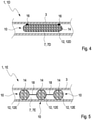
- Fig. 4
- eine schematische Schnittdarstellung eines vierten Ausführungsbeispiels einer Rohbaustruktur mit einem vierten Ausführungsbeispiel eines Verstärkungsmittel zur Stabilisierung eines durch verbundene Hohlprofile gebildeten Hohlraums; und
- Fig. 5
- eine schematische Schnittdarstellung eines fünften Ausführungsbeispiels einer Rohbaustruktur mit einem fünften Ausführungsbeispiel eines Verstärkungsmittel zur Stabilisierung eines durch verbundene Hohlprofile gebildeten Hohlraums.
- Wie aus
Fig. 1 bis 5 ersichtlich ist, weist die Rohbaustruktur 1, 1A, 1B, 1C, 1D, 1E in den dargestellten Ausführungsbeispielen mindestens einen durch verbundene Hohlprofile 3, 5 gebildeten Hohlraum 7, 7A, 7B, 7C, 7D, 7E auf. In welchen zur Stabilisierung mindestens ein erfindungsgemäßes Verstärkungsmittel 10 eingebracht ist. - Wie aus
Fig. 1 bis 5 weiter ersichtlich ist, umfasst das Verstärkungsmittel 10 zur Stabilisierung eines durch verbundene Hohlprofile 3, 5 gebildeten Hohlraums 7, 7A, 7B, 7C, 7D, 7E jeweils eine dehnbare Hülle 12, 12A, 12B, 12C, 12D, 12E und Schüttgut 14, welches in der dehnbaren Hülle 12, 12A, 12B, 12C, 12D, 12E eingeschlossen ist. Hierbei ist das Schüttgut 14 derart ausgestaltet, dass es bei Einwirkung einer Aktivierungstemperatur expandiert und sich zu einem Masseblock verbindet. Die dehnbare Hülle 12, 12A, 12B, 12C, 12D, 12E ist derart ausgestaltet, dass sie eine Verdichtung und einen Druckaufbau des expandierenden Schüttguts 14 bewirkt. - In den dargestellten Ausführungsbeispielen ist das expandierende Schüttgut 14 in der dehnbare Hülle 12, 12A, 12B, 12C, 12D, 12E eingeschweißt und in zu stabilisierenden Hohlräume 7, 7A, 7B, 7C, 7D, 7E der Rohbaustrukturen 1, 1A, 1B, 1C, 1D, 1E eingebracht. Wie aus
Fig. 1 bis 5 weiter ersichtlich ist, ist eine geometrische Grundform der jeweiligen dehnbaren Hülle 12, 12A, 12B, 12C, 12D, 12E an eine geometrische Form des zugehörigen Hohlraums 7, 7A, 7B, 7C, 7D, 7E angepasst, in welche das Verstärkungsmittel 10 eingebracht ist. Beim Durchlaufen eines Trocknungsofens während der Lackierung der korrespondierenden Rohbaustruktur 1, 1A, 1B, 1C, 1D, 1E expandiert das Schüttgut 14 und verscheißt durch den begrenzten Raum bei der Expansion innerhalb der dehnbaren Hülle 12, 12A, 12B, 12C, 12D, 12E zu einem Masseblock, welcher den zugehörigen Hohlraum 7, 7A, 7B, 7C, 7D, 7E zumindest teilweise ausfüllt.Fig. 1 bis 5 zeigen das Verstärkungsmittel 10 jeweils vor dem Durchlaufen des Trocknungsofens, d.h. vor der Expansion des Schüttguts 14. Die dehnbare Hülle 12, 12A, 12B, 12C, 12D. 12E sorgt für Verdichtung und den Druckaufbau des zu expandierenden Schüttguts 14. Damit wird eine Versteifung in der Rohbaustruktur 1, 1A, 1B, 1C, 1D. 1E ohne zusätzlichen Aufwand erzielt und der gesamte Bauraum genutzt. Die dehnbare Hülle 12, 12A, 12B, 12C, 12D, 12E kann einfach im Hohlraum 7, 7A, 7B, 7C, 7D, 7E der Hohlprofile 3, 5 verbleiben eine zusätzliche Verstärkung der Rohbaustruktur 1, 1A, 1B, 1C, 1D, 1E bewirken. Der Masseblock ist derart ausgestaltet, dass er eine mechanisch stabilisierende Wirkung und/oder eine schalldämmende Wirkung aufweist. - Die Hohlprofile 3, 5 umfassen beispielsweise jeweils zwei Halbschalen, welche eine Abstützung für die dehnbare Hülle 12, 12A, 12B, 12C, 12D, 12E mit dem expandierenden Schüttgut 14 ausbilden. Die Hohlprofile 3, 5 sind vorzugsweise aus einem Verbundmaterial oder aus einem Leichtmetall, wie Aluminium, Magnesium usw., oder aus einer Metalllegierung hergestellt und bilden beispielsweise ein Strukturbauteil wie einen Schweller, einen Längsträger, einen Querträger oder eine Säule der Rohbaustruktur 1, 1A, 1B, 1C, 1D, 1E aus. Aufgrund des geringen Gewichts kann die dehnbare Hülle 12, 12A, 12B, 12C, 12D, 12E im Hohlraum 7, 7A, 7B, 7C, 7D, 7E belassen werden, ohne dass das Gewicht der Rohbaustruktur 1, 1A, 1B, 1C, 1D, 1E signifikant erhöht wird. Das expandierte Schüttgut 14 in der dehnbaren Hülle 12, 12A, 12B, 12C, 12D, 12E füllt den Hohlraum 7, 7A, 7B, 7C, 7D, 7E zumindest teilweise aus, ohne dass Spalten zur Strukturverstärkung entstehen. In einer bevorzugten Ausführungsform haftet die dehnbare Hülle 12, 12A, 12B, 12C, 12D an der Wandung des Hohlraums 7, 7A, 7B, 7C, 7D.
- Das Schüttgut 14 kann an die spezifischen Anforderungen angepasst, variiert und kombiniert werden. Das Schüttgut 14 kann beispielsweise als granulatähnliches Füllmaterial überwiegend duroplastische oder thermoplastische Partikel aufweisen. Alternativ kann das Schüttgut 14 überwiegend ein Gemisch aus expandierbarem Material und Füllstoffen wie Blähgas, Metallkugeln, Tonkugeln und/oder Aluminiumpartikeln aufweisen. Zudem kann innerhalb der Hülle 12 eine wabenähnliche Verstärkung angeordnet werden, welche vom expandierten Schüttgut 14 eingeschlossen ist.
- In den dargestellten Ausführungsbeispielen bildet eine Verbundfolie die dehnbare Hülle 12, 12A, 12B, 12C, 12D, 12E aus. Zusätzlich kann eine Metallfolie und/oder eine textile Deckschicht die Verbundfolie verstärken. In den dargestellten Ausführungsbeispielen schmilzt die dehnbare Hülle 12, 12A, 12B, 12C, 12D, 12E bei Temperatureinwirkung an der Außenseite auf und haftet als Haftvermittler an der zu verstärkenden Rohbaustruktur 1, 1A, 1B, 1C, 1D, 1E. Nach dem Erkalten verfestigt sich die dehnbare Hülle 12, 12A, 12B, 12C, 12D, 12E an der Wandung des Hohlraum 7, 7A, 7B, 7C, 7D, 7E bzw. an der zu verstärkenden Rohbaustruktur 1, 1A, 1B, 1C, 1D, 1E und verstärkt diese zusätzlich. Die Textilschicht kann gezielt mit Verstärkungsfasern aus Glas, Kohle, Polyaramide oder Metall verstärkt werden, welche in Belastungsrichtung verlaufen.
- Das erfindungsgemäße Verfahren zur Hohlraumverstärkung einer Rohbaustruktur 1 mit wenigstens einem durch verbundene Hohlprofile 3, 5 gebildeten Hohlraum 7, umfasst folgende Schritte: Bereitstellen eines oben beschriebenen Verstärkungsmittels 10. Einführen des Verstärkungsmittels 10 in den durch verbundene Hohlprofile 3, 5 gebildeten Hohlraum 7, 7A, 7B, 7C, 7D, 7E. Erwärmen des Verstärkungsmittels 10 auf wenigstens die Aktivierungstemperatur, so dass dessen Schüttgut 14 expandiert und sich zu einem Masseblock verbindet.
- Das Erwärmen des Verstärkungsmittels 10 erfolgt bei den dargestellten Ausführungsbeispielen vorzugsweise während eines Durchlauf eines Trocknungsofens bei einem Lackierprozess der Rohbaustruktur 1, 1A, 1B, 1C, 1D, 1E.
- Wie aus
Fig. 1 weiter ersichtlich ist, umfasst die Rohbaustruktur 1 im dargestellten ersten Ausführungsbeispiel einen Verbindungsknoten 1A, an welchem ein erstes Hohlprofil 3 mit einem zweiten Hohlprofil 5 verbunden ist. Wie ausFig. 1 weiter ersichtlich ist, weist der ausgebildete Hohlraum 7A und die mit Schüttgut 14 gefüllte dehnbare Hülle 12Ajeweils eine T-Form auf. Durch diese geometrische Grundform der dehnbaren Hülle 12A kann das Verstärkungsmittel 10 nicht im Verbindungsknoten 1A verrutschen. - Wie aus
Fig. 2 weiter ersichtlich ist, umfasst die Rohbaustruktur 1 im dargestellten zweiten Ausführungsbeispiel ein Hohlprofil 3 mit einem Knick 1B. Wie ausFig. 2 weiter ersichtlich ist, weist der ausgebildete Hohlraum 7B und die mit Schüttgut 14 gefüllte dehnbare Hülle 12B jeweils ebenfalls einen Knick 1B auf. Durch diese geometrische Grundform der dehnbaren Hülle 12B kann das Verstärkungsmittel 10 nicht im Knick 1B verrutschen. - Wie aus
Fig. 3 weiter ersichtlich ist, umfasst die Rohbaustruktur 1 im dargestellten dritten Ausführungsbeispiel ein Hohlprofil 3 mit einer Verjüngung 1C. Wie ausFig. 3 weiter ersichtlich ist, weist der ausgebildete Hohlraum 7C und die mit Schüttgut 14 gefüllte dehnbare Hülle 12C jeweils ebenfalls eine Verjüngung 1C auf. Durch diese geometrische Grundform der dehnbaren Hülle 12C kann das Verstärkungsmittel 10 nicht an der Verjüngung 1C verrutschen. - Wie aus
Fig. 4 weiter ersichtlich ist, umfasst die Rohbaustruktur 1 im dargestellten vierten Ausführungsbeispiel ein als gerader Träger 1D ausgeführtes Hohlprofil 3. Wie ausFig. 4 weiter ersichtlich ist, ist die mit Schüttgut 14 gefüllte dehnbare Hülle 12D an zwei Fixierungspunkten 16 an der Wandung des ausgebildeten Hohlraums 7D vorfixiert, so dass das Verstärkungsmittel 10 nicht im Träger 1D verrutschen kann. - Wie aus
Fig. 5 weiter ersichtlich ist, umfasst die Rohbaustruktur 1 im dargestellten fünften Ausführungsbeispiel analog zum vierten Ausführungsbeispiel ein als gerader Träger 1E ausgeführtes Hohlprofil 3. Wie ausFig. 5 weiter ersichtlich ist, sind im dargestellten Ausführungsbeispiel mehrere Verstärkungsmittel 10 in dem Hohlraum 7E angeordnet, welche über Verbindungselemente 18 miteinander verbunden sind. Durch die Länge der Verbindungselemente 18 kann der Abstand zwischen zwei benachbarten Verstärkungsmitteln 10 vorgegeben werden. Im dargestellten fünften Ausführungsbeispiel ist die gemeinsame Hülle 12E der drei Verstärkungsmittel 10 als Schlauch ausgeführt, welcher abschnittsweise mit Schüttgut 14 gefüllt ist. Die nicht mit Schüttgut 14 gefüllten Abschnitte des Schlauchs sind verklebt bzw. verschweißt und bilden die Verbindungselemente 18 zwischen zwei benachbarten Verstärkungsmitteln 10 aus. - Bei Ausführungsformen der vorliegenden Erfindung können zusätzliche Arbeitsschritte zum Herstellen und Fügen von Verstärkungsteilen, Schottelementen in vorteilhafter Weise eingespart werden, so dass eine kostengünstige Herstellung der Rohbaustruktur bzw. des Verstärkungsmittels ermöglicht wird. Ausführungsformen der Erfindung können für Karossen in Schalenbauweise, Spaceframebauweise, Monococks, aber auch für strukturverstärkende Profile und Crashrohre eingesetzt werden.
-
- 1
- Rohbaustruktur
- 1A
- Verbindungsknoten
- 1B
- Knick
- 1C
- Verjüngung
- 1D, 1E
- Träger
- 3
- erstes Hohlprofil
- 5
- zweites Hohlprofil
- 7, 7A, 7B, 7C, 7D, 7E
- Hohlraum
- 10
- Verstärkungsmittel
- 12, 12A, 12B, 12C, 12D, 12E
- dehnbare Hülle
- 14
- Schüttgut
- 16
- Fixierungsstelle
- 18
- Verbindungselement
Claims (12)
- Verstärkungsmittel (10) zur Stabilisierung eines durch verbundene Hohlprofile (3, 5) gebildeten Hohlraums (7), umfassend:- eine dehnbare Hülle (12), und- Schüttgut (14), welches in der dehnbaren Hülle (12) eingeschlossen ist, wobei das Schüttgut (14) derart ausgestaltet ist, dass es bei Einwirkung einer Aktivierungstemperatur expandiert und sich zu einem Masseblock verbindet, und wobei die dehnbare Hülle (12) derart ausgestaltet ist, dass sie eine Verdichtung und einen Druckaufbau des expandierenden Schüttguts (14) bewirkt.
- Verstärkungsmittel (10) nach Anspruch 1, dadurch gekennzeichnet, dass das Schüttgut (14) als granulatähnliches Füllmaterial überwiegend duroplastische oder thermoplastische Partikel oder überwiegend ein Gemisch aus expandierbarem Material und Füllstoffen wie Blähgas, Metallkugeln, Tonkugeln und/oder Aluminiumpartikeln aufweist.
- Verstärkungsmittel (10) nach Anspruch 1 oder 2, dadurch gekennzeichnet, dass eine wabenähnliche Verstärkung innerhalb der Hülle (12) angeordnet ist, welche vom expandierten Schüttgut (14) eingeschlossen ist.
- Verstärkungsmittel (10) nach einem der Ansprüche 1 bis 3, dadurch gekennzeichnet, dass eine geometrische Grundform der dehnbaren Hülle (12) an eine geometrische Form des Hohlraums (7) angepasst ist.
- Verstärkungsmittel (10) nach einem der Ansprüche 1 bis 4, dadurch gekennzeichnet, dass eine Verbundfolie die dehnbare Hülle (12) ausbildet.
- Verstärkungsmittel (10) nach Anspruch 5, dadurch gekennzeichnet, dass eine Metallfolie und/oder eine textile Deckschicht die Verbundfolie verstärken.
- Verfahren zur Hohlraumverstärkung einer Rohbaustruktur (1) mit wenigstens einem durch verbundene Hohlprofile (3, 5) gebildeten Hohlraum (7), umfassend folgende Schritte:- Bereitstellen mindestens eines Verstärkungsmittels (10), welches nach zumindest einem der Ansprüche 1 bis 6 ausgeführt ist,- Einführen des mindestens einen Verstärkungsmittels (10) in den durch verbundene Hohlprofile (3, 5) gebildeten Hohlraum (7),- Erwärmen des mindestens einen Verstärkungsmittels (10) auf wenigstens die Aktivierungstemperatur, so dass dessen Schüttgut (14) expandiert und sich zu einem Masseblock verbindet.
- Verfahren nach 7, dadurch gekennzeichnet, dass der Masseblock derart ausgestaltet ist, dass er eine mechanisch stabilisierende Wirkung und/oder eine schalldämmende Wirkung aufweist.
- Verfahren nach Anspruch 7 oder 8, dadurch gekennzeichnet, dass die dehnbare Hülle (12) bei Temperatureinwirkung an der Außenseite aufschmilzt und als Haftvermittler an der zu verstärkenden Rohbaustruktur (1) haftet und diese nach dem Erkalten und Verfestigen verstärkt.
- Verfahren nach einem der Ansprüche 7 bis 9, dadurch gekennzeichnet, dass ein Erwärmen des mindestens einen Verstärkungsmittels (10) während eines Durchlauf eines Trocknungsofens beim Lackierprozess erfolgt.
- Verfahren nach einem der Ansprüche 7 bis 10, dadurch gekennzeichnet, dass mindestens zwei Verstärkungsmittel (10) in einem Hohlraum (7) über ein Verbindungselement (18) miteinander verbunden werden.
- Verfahren nach 11, dadurch gekennzeichnet, dass die mindestens zwei Verstärkungsmittel (10) eine gemeinsame Hülle (12) aufweisen, welche abschnittsweise nicht mit Schüttgut (14) gefüllt wird, wobei der nicht mit Schüttgut (14) gefüllte Abschnitt der Hülle (12) das Verbindungselement (18) zwischen den mindestens zwei Verstärkungsmitteln (10) ausbildet.
Applications Claiming Priority (2)
| Application Number | Priority Date | Filing Date | Title |
|---|---|---|---|
| DE102018202444.8A DE102018202444A1 (de) | 2018-02-19 | 2018-02-19 | Verstärkungsmittel und Verfahren zur Hohlraumverstärkung einer Rohbaustruktur |
| PCT/EP2019/052752 WO2019158396A1 (de) | 2018-02-19 | 2019-02-05 | Verstärkungsmittel und verfahren zur hohlraumverstärkung einer rohbaustruktur |
Publications (2)
| Publication Number | Publication Date |
|---|---|
| EP3755604A1 EP3755604A1 (de) | 2020-12-30 |
| EP3755604B1 true EP3755604B1 (de) | 2022-03-02 |
Family
ID=65363280
Family Applications (1)
| Application Number | Title | Priority Date | Filing Date |
|---|---|---|---|
| EP19704279.9A Active EP3755604B1 (de) | 2018-02-19 | 2019-02-05 | Verstärkungsmittel und verfahren zur hohlraumverstärkung einer rohbaustruktur |
Country Status (5)
| Country | Link |
|---|---|
| EP (1) | EP3755604B1 (de) |
| CN (1) | CN111712426A (de) |
| DE (1) | DE102018202444A1 (de) |
| ES (1) | ES2909615T3 (de) |
| WO (1) | WO2019158396A1 (de) |
Families Citing this family (2)
| Publication number | Priority date | Publication date | Assignee | Title |
|---|---|---|---|---|
| DE102024102986A1 (de) | 2024-02-02 | 2025-08-07 | Audi Aktiengesellschaft | Verfahren zum Herstellen einer Batterieanordnung für ein Kraftfahrzeug und Batterieanordnung für ein Kraftfahrzeug |
| DE102024113972A1 (de) * | 2024-05-17 | 2025-11-20 | Bayerische Motoren Werke Aktiengesellschaft | Profilbauteil für eine Karosserie eines Fahrzeugs sowie Fahrzeug |
Family Cites Families (15)
| Publication number | Priority date | Publication date | Assignee | Title |
|---|---|---|---|---|
| FR1418850A (fr) * | 1964-06-01 | 1965-11-26 | Simca Automobiles Sa | Procédé d'obturation d'un corps creux en un point déterminé |
| DE3826011A1 (de) * | 1988-07-30 | 1990-02-01 | Bayerische Motoren Werke Ag | Verfahren und vorrichtung zum ausschaeumen von hohlraeumen, insbesondere einer fahrzeugkarosserie |
| DE4028895C1 (en) * | 1990-09-12 | 1992-02-20 | Mercedes-Benz Aktiengesellschaft, 7000 Stuttgart, De | Foamed component made of elastic, flexible plastic - used for sound insulation, consists of hollow chassis into which polyurethane foam unit is adhered inside and unit is seated |
| JPH07232665A (ja) * | 1994-02-24 | 1995-09-05 | Nippon Tokushu Toryo Co Ltd | 自動車の防音処理工法 |
| DE19707462C1 (de) | 1997-02-25 | 1998-06-18 | Bayerische Motoren Werke Ag | Gepanzertes Kraftfahrzeug mit verstärkten Karosseriebauteilen |
| DE19727907C2 (de) * | 1997-07-01 | 1999-10-14 | Daimler Chrysler Ag | Verfahren zum Füllen von Doppelwandungshohlräumen eines Doppelwandigenauspuffrohres und doppelwandiges, insbesondere abgasführendes Rohr |
| DE19810706C2 (de) | 1998-03-12 | 2002-09-12 | Thyssenkrupp Stahl Ag | Doppellagenblech aus zwei Deckblechen und einer Zwischenlage |
| US7169344B2 (en) * | 2002-04-26 | 2007-01-30 | L&L Products, Inc. | Method of reinforcing at least a portion of a structure |
| JP2004262096A (ja) * | 2003-02-28 | 2004-09-24 | Tokai Rubber Ind Ltd | 中空部材への発泡体の充填方法 |
| DE102007059183A1 (de) * | 2007-12-06 | 2009-06-10 | Henkel Ag & Co. Kgaa | Verfahren zur Verstärkung, Dämmung, Dämpfung und/oder Abdichtung von Hohlbauteilen |
| DE102010012722A1 (de) | 2010-03-25 | 2010-10-21 | Daimler Ag | Versteifungsstrebe für ein Kraftfahrzeug |
| US20120235442A1 (en) * | 2011-03-16 | 2012-09-20 | GM Global Technology Operations LLC | Reinforced structural assembly with acoustic foam member and method of reinforcing vehicle components |
| DE102013214761A1 (de) * | 2013-07-29 | 2015-01-29 | Bayerische Motoren Werke Aktiengesellschaft | Stützteil einer Fahrzeugkarosserie |
| CN203651910U (zh) * | 2013-12-06 | 2014-06-18 | 全耐塑料公司 | 机动车车身部件及包含该部件的机动车 |
| EP2883781A1 (de) * | 2013-12-13 | 2015-06-17 | Sika Technology AG | Leichtbau -Verstärkungselement und ein Verfahren zur Herstellung einer solchen Verstärkungselement |
-
2018
- 2018-02-19 DE DE102018202444.8A patent/DE102018202444A1/de not_active Withdrawn
-
2019
- 2019-02-05 CN CN201980012593.4A patent/CN111712426A/zh active Pending
- 2019-02-05 EP EP19704279.9A patent/EP3755604B1/de active Active
- 2019-02-05 ES ES19704279T patent/ES2909615T3/es active Active
- 2019-02-05 WO PCT/EP2019/052752 patent/WO2019158396A1/de not_active Ceased
Also Published As
| Publication number | Publication date |
|---|---|
| ES2909615T3 (es) | 2022-05-09 |
| EP3755604A1 (de) | 2020-12-30 |
| WO2019158396A1 (de) | 2019-08-22 |
| CN111712426A (zh) | 2020-09-25 |
| DE102018202444A1 (de) | 2019-06-19 |
Similar Documents
| Publication | Publication Date | Title |
|---|---|---|
| DE69800612T2 (de) | Verstärktes Bauelement | |
| DE60213571T2 (de) | Strukturschaumstoff | |
| EP1064188B1 (de) | Hohlprofil mit innenversteifung und verfahren zur herstellung dieses hohlprofils | |
| EP0889012B1 (de) | Verfahren zum Füllen von Hohlräumen in Werkstücken oder Halbzeugen und Bauelement zum An- oder Einbau in ein Kraftfahrzeug | |
| DE102017006057B4 (de) | Crashelement | |
| DE19648164A1 (de) | Karosserieteil, insbesondere Profilrahmenträger | |
| DE29514164U1 (de) | Ausgeschäumtes Formteil | |
| DE102013209097A1 (de) | Baugruppe in Faserverbundbauweise für ein Kraftfahrzeug | |
| EP3421331B1 (de) | System eines verstärkten strukturelementes eines kraftfahrzeugs | |
| DE102005041894B4 (de) | Trägerelement, insbesondere in einem Kraftfahrzeug | |
| DE102018207221A1 (de) | Energieabsorptionsbauteil für die Anordnung in einem hohlprofilartigen Schweller | |
| EP2999616B1 (de) | Achsträger eines fahrzeugs | |
| DE10134372A1 (de) | Verfahren zur Herstellung einer Hybridstruktur aus Metall und faserverstärktem Kunststoff sowie Hybridstruktur | |
| DE102011075012A1 (de) | Verbundplatte | |
| DE102012010463A1 (de) | Rohbaustruktur für ein Kraftfahrzeug und Verfahren zum Herstellen einer solchen Rohbaustruktur | |
| EP2181018A1 (de) | Struktur für einen fahrzeugsitz | |
| WO2019158396A1 (de) | Verstärkungsmittel und verfahren zur hohlraumverstärkung einer rohbaustruktur | |
| DE10032556B4 (de) | Verfahren zur Herstellung eines Karosseriebauteils in Sandwichbauweise sowie Vorrichtung zur Durchführung des Verfahrens | |
| EP3079876B1 (de) | Verfahren zur herstellung eines fahrzeug-karosserieelements sowie fahrzeug karosserieelement | |
| DE102020005838A1 (de) | Verstärkter Fahrzeugseitenschweller zwischen einem Träger und einem Boden eines Fahrzeuges | |
| EP1410976A1 (de) | Profilträger | |
| EP0287941A1 (de) | Verfahren zum Versteifen des metallischen Chassis, insbesondere der Bodengruppe von Personenkraftwagen | |
| DE102019201415B4 (de) | Karosserieteil und Verfahren zum Herstellen eines Karosserieteils | |
| DE102015014356B3 (de) | Knotenstruktur mit wenigstens einem doppelwandigen Hohlprofilbauteil, Verfahren zur Herstellung und Fahrzeugkarosserie | |
| DE102010012722A1 (de) | Versteifungsstrebe für ein Kraftfahrzeug |
Legal Events
| Date | Code | Title | Description |
|---|---|---|---|
| STAA | Information on the status of an ep patent application or granted ep patent |
Free format text: STATUS: UNKNOWN |
|
| STAA | Information on the status of an ep patent application or granted ep patent |
Free format text: STATUS: THE INTERNATIONAL PUBLICATION HAS BEEN MADE |
|
| PUAI | Public reference made under article 153(3) epc to a published international application that has entered the european phase |
Free format text: ORIGINAL CODE: 0009012 |
|
| STAA | Information on the status of an ep patent application or granted ep patent |
Free format text: STATUS: REQUEST FOR EXAMINATION WAS MADE |
|
| 17P | Request for examination filed |
Effective date: 20200921 |
|
| AK | Designated contracting states |
Kind code of ref document: A1 Designated state(s): AL AT BE BG CH CY CZ DE DK EE ES FI FR GB GR HR HU IE IS IT LI LT LU LV MC MK MT NL NO PL PT RO RS SE SI SK SM TR |
|
| AX | Request for extension of the european patent |
Extension state: BA ME |
|
| DAV | Request for validation of the european patent (deleted) | ||
| DAX | Request for extension of the european patent (deleted) | ||
| GRAP | Despatch of communication of intention to grant a patent |
Free format text: ORIGINAL CODE: EPIDOSNIGR1 |
|
| STAA | Information on the status of an ep patent application or granted ep patent |
Free format text: STATUS: GRANT OF PATENT IS INTENDED |
|
| INTG | Intention to grant announced |
Effective date: 20211112 |
|
| GRAS | Grant fee paid |
Free format text: ORIGINAL CODE: EPIDOSNIGR3 |
|
| GRAA | (expected) grant |
Free format text: ORIGINAL CODE: 0009210 |
|
| STAA | Information on the status of an ep patent application or granted ep patent |
Free format text: STATUS: THE PATENT HAS BEEN GRANTED |
|
| AK | Designated contracting states |
Kind code of ref document: B1 Designated state(s): AL AT BE BG CH CY CZ DE DK EE ES FI FR GB GR HR HU IE IS IT LI LT LU LV MC MK MT NL NO PL PT RO RS SE SI SK SM TR |
|
| REG | Reference to a national code |
Ref country code: GB Ref legal event code: FG4D Free format text: NOT ENGLISH |
|
| REG | Reference to a national code |
Ref country code: CH Ref legal event code: EP Ref country code: AT Ref legal event code: REF Ref document number: 1472029 Country of ref document: AT Kind code of ref document: T Effective date: 20220315 |
|
| REG | Reference to a national code |
Ref country code: DE Ref legal event code: R096 Ref document number: 502019003568 Country of ref document: DE |
|
| REG | Reference to a national code |
Ref country code: IE Ref legal event code: FG4D Free format text: LANGUAGE OF EP DOCUMENT: GERMAN |
|
| REG | Reference to a national code |
Ref country code: ES Ref legal event code: FG2A Ref document number: 2909615 Country of ref document: ES Kind code of ref document: T3 Effective date: 20220509 |
|
| REG | Reference to a national code |
Ref country code: LT Ref legal event code: MG9D |
|
| REG | Reference to a national code |
Ref country code: NL Ref legal event code: MP Effective date: 20220302 |
|
| PG25 | Lapsed in a contracting state [announced via postgrant information from national office to epo] |
Ref country code: SE Free format text: LAPSE BECAUSE OF FAILURE TO SUBMIT A TRANSLATION OF THE DESCRIPTION OR TO PAY THE FEE WITHIN THE PRESCRIBED TIME-LIMIT Effective date: 20220302 Ref country code: RS Free format text: LAPSE BECAUSE OF FAILURE TO SUBMIT A TRANSLATION OF THE DESCRIPTION OR TO PAY THE FEE WITHIN THE PRESCRIBED TIME-LIMIT Effective date: 20220302 Ref country code: NO Free format text: LAPSE BECAUSE OF FAILURE TO SUBMIT A TRANSLATION OF THE DESCRIPTION OR TO PAY THE FEE WITHIN THE PRESCRIBED TIME-LIMIT Effective date: 20220602 Ref country code: LT Free format text: LAPSE BECAUSE OF FAILURE TO SUBMIT A TRANSLATION OF THE DESCRIPTION OR TO PAY THE FEE WITHIN THE PRESCRIBED TIME-LIMIT Effective date: 20220302 Ref country code: HR Free format text: LAPSE BECAUSE OF FAILURE TO SUBMIT A TRANSLATION OF THE DESCRIPTION OR TO PAY THE FEE WITHIN THE PRESCRIBED TIME-LIMIT Effective date: 20220302 Ref country code: BG Free format text: LAPSE BECAUSE OF FAILURE TO SUBMIT A TRANSLATION OF THE DESCRIPTION OR TO PAY THE FEE WITHIN THE PRESCRIBED TIME-LIMIT Effective date: 20220602 |
|
| PG25 | Lapsed in a contracting state [announced via postgrant information from national office to epo] |
Ref country code: PL Free format text: LAPSE BECAUSE OF FAILURE TO SUBMIT A TRANSLATION OF THE DESCRIPTION OR TO PAY THE FEE WITHIN THE PRESCRIBED TIME-LIMIT Effective date: 20220302 Ref country code: LV Free format text: LAPSE BECAUSE OF FAILURE TO SUBMIT A TRANSLATION OF THE DESCRIPTION OR TO PAY THE FEE WITHIN THE PRESCRIBED TIME-LIMIT Effective date: 20220302 Ref country code: GR Free format text: LAPSE BECAUSE OF FAILURE TO SUBMIT A TRANSLATION OF THE DESCRIPTION OR TO PAY THE FEE WITHIN THE PRESCRIBED TIME-LIMIT Effective date: 20220603 Ref country code: FI Free format text: LAPSE BECAUSE OF FAILURE TO SUBMIT A TRANSLATION OF THE DESCRIPTION OR TO PAY THE FEE WITHIN THE PRESCRIBED TIME-LIMIT Effective date: 20220302 |
|
| PG25 | Lapsed in a contracting state [announced via postgrant information from national office to epo] |
Ref country code: NL Free format text: LAPSE BECAUSE OF FAILURE TO SUBMIT A TRANSLATION OF THE DESCRIPTION OR TO PAY THE FEE WITHIN THE PRESCRIBED TIME-LIMIT Effective date: 20220302 |
|
| PG25 | Lapsed in a contracting state [announced via postgrant information from national office to epo] |
Ref country code: SM Free format text: LAPSE BECAUSE OF FAILURE TO SUBMIT A TRANSLATION OF THE DESCRIPTION OR TO PAY THE FEE WITHIN THE PRESCRIBED TIME-LIMIT Effective date: 20220302 Ref country code: SK Free format text: LAPSE BECAUSE OF FAILURE TO SUBMIT A TRANSLATION OF THE DESCRIPTION OR TO PAY THE FEE WITHIN THE PRESCRIBED TIME-LIMIT Effective date: 20220302 Ref country code: RO Free format text: LAPSE BECAUSE OF FAILURE TO SUBMIT A TRANSLATION OF THE DESCRIPTION OR TO PAY THE FEE WITHIN THE PRESCRIBED TIME-LIMIT Effective date: 20220302 Ref country code: PT Free format text: LAPSE BECAUSE OF FAILURE TO SUBMIT A TRANSLATION OF THE DESCRIPTION OR TO PAY THE FEE WITHIN THE PRESCRIBED TIME-LIMIT Effective date: 20220704 Ref country code: EE Free format text: LAPSE BECAUSE OF FAILURE TO SUBMIT A TRANSLATION OF THE DESCRIPTION OR TO PAY THE FEE WITHIN THE PRESCRIBED TIME-LIMIT Effective date: 20220302 Ref country code: CZ Free format text: LAPSE BECAUSE OF FAILURE TO SUBMIT A TRANSLATION OF THE DESCRIPTION OR TO PAY THE FEE WITHIN THE PRESCRIBED TIME-LIMIT Effective date: 20220302 |
|
| PG25 | Lapsed in a contracting state [announced via postgrant information from national office to epo] |
Ref country code: IS Free format text: LAPSE BECAUSE OF FAILURE TO SUBMIT A TRANSLATION OF THE DESCRIPTION OR TO PAY THE FEE WITHIN THE PRESCRIBED TIME-LIMIT Effective date: 20220702 Ref country code: AL Free format text: LAPSE BECAUSE OF FAILURE TO SUBMIT A TRANSLATION OF THE DESCRIPTION OR TO PAY THE FEE WITHIN THE PRESCRIBED TIME-LIMIT Effective date: 20220302 |
|
| REG | Reference to a national code |
Ref country code: DE Ref legal event code: R097 Ref document number: 502019003568 Country of ref document: DE |
|
| PLBE | No opposition filed within time limit |
Free format text: ORIGINAL CODE: 0009261 |
|
| STAA | Information on the status of an ep patent application or granted ep patent |
Free format text: STATUS: NO OPPOSITION FILED WITHIN TIME LIMIT |
|
| PG25 | Lapsed in a contracting state [announced via postgrant information from national office to epo] |
Ref country code: DK Free format text: LAPSE BECAUSE OF FAILURE TO SUBMIT A TRANSLATION OF THE DESCRIPTION OR TO PAY THE FEE WITHIN THE PRESCRIBED TIME-LIMIT Effective date: 20220302 |
|
| 26N | No opposition filed |
Effective date: 20221205 |
|
| PG25 | Lapsed in a contracting state [announced via postgrant information from national office to epo] |
Ref country code: SI Free format text: LAPSE BECAUSE OF FAILURE TO SUBMIT A TRANSLATION OF THE DESCRIPTION OR TO PAY THE FEE WITHIN THE PRESCRIBED TIME-LIMIT Effective date: 20220302 |
|
| P01 | Opt-out of the competence of the unified patent court (upc) registered |
Effective date: 20230530 |
|
| PG25 | Lapsed in a contracting state [announced via postgrant information from national office to epo] |
Ref country code: MC Free format text: LAPSE BECAUSE OF FAILURE TO SUBMIT A TRANSLATION OF THE DESCRIPTION OR TO PAY THE FEE WITHIN THE PRESCRIBED TIME-LIMIT Effective date: 20220302 |
|
| REG | Reference to a national code |
Ref country code: CH Ref legal event code: PL |
|
| REG | Reference to a national code |
Ref country code: BE Ref legal event code: MM Effective date: 20230228 |
|
| PG25 | Lapsed in a contracting state [announced via postgrant information from national office to epo] |
Ref country code: LU Free format text: LAPSE BECAUSE OF NON-PAYMENT OF DUE FEES Effective date: 20230205 Ref country code: LI Free format text: LAPSE BECAUSE OF NON-PAYMENT OF DUE FEES Effective date: 20230228 Ref country code: CH Free format text: LAPSE BECAUSE OF NON-PAYMENT OF DUE FEES Effective date: 20230228 |
|
| REG | Reference to a national code |
Ref country code: IE Ref legal event code: MM4A |
|
| PG25 | Lapsed in a contracting state [announced via postgrant information from national office to epo] |
Ref country code: IE Free format text: LAPSE BECAUSE OF NON-PAYMENT OF DUE FEES Effective date: 20230205 |
|
| PG25 | Lapsed in a contracting state [announced via postgrant information from national office to epo] |
Ref country code: BE Free format text: LAPSE BECAUSE OF NON-PAYMENT OF DUE FEES Effective date: 20230228 |
|
| REG | Reference to a national code |
Ref country code: AT Ref legal event code: MM01 Ref document number: 1472029 Country of ref document: AT Kind code of ref document: T Effective date: 20240205 |
|
| PG25 | Lapsed in a contracting state [announced via postgrant information from national office to epo] |
Ref country code: AT Free format text: LAPSE BECAUSE OF NON-PAYMENT OF DUE FEES Effective date: 20240205 |
|
| PG25 | Lapsed in a contracting state [announced via postgrant information from national office to epo] |
Ref country code: CY Free format text: LAPSE BECAUSE OF FAILURE TO SUBMIT A TRANSLATION OF THE DESCRIPTION OR TO PAY THE FEE WITHIN THE PRESCRIBED TIME-LIMIT; INVALID AB INITIO Effective date: 20190205 |
|
| PG25 | Lapsed in a contracting state [announced via postgrant information from national office to epo] |
Ref country code: HU Free format text: LAPSE BECAUSE OF FAILURE TO SUBMIT A TRANSLATION OF THE DESCRIPTION OR TO PAY THE FEE WITHIN THE PRESCRIBED TIME-LIMIT; INVALID AB INITIO Effective date: 20190205 |
|
| PG25 | Lapsed in a contracting state [announced via postgrant information from national office to epo] |
Ref country code: TR Free format text: LAPSE BECAUSE OF FAILURE TO SUBMIT A TRANSLATION OF THE DESCRIPTION OR TO PAY THE FEE WITHIN THE PRESCRIBED TIME-LIMIT Effective date: 20220302 |
|
| PGFP | Annual fee paid to national office [announced via postgrant information from national office to epo] |
Ref country code: GB Payment date: 20260219 Year of fee payment: 8 |
|
| PGFP | Annual fee paid to national office [announced via postgrant information from national office to epo] |
Ref country code: ES Payment date: 20260319 Year of fee payment: 8 |
|
| PGFP | Annual fee paid to national office [announced via postgrant information from national office to epo] |
Ref country code: DE Payment date: 20260228 Year of fee payment: 8 |
|
| PGFP | Annual fee paid to national office [announced via postgrant information from national office to epo] |
Ref country code: AT Payment date: 20260410 Year of fee payment: 5 |
|
| PGFP | Annual fee paid to national office [announced via postgrant information from national office to epo] |
Ref country code: IT Payment date: 20260227 Year of fee payment: 8 |
|
| PGFP | Annual fee paid to national office [announced via postgrant information from national office to epo] |
Ref country code: FR Payment date: 20260219 Year of fee payment: 8 |