EP3755586B1 - Wischervorrichtung - Google Patents
Wischervorrichtung Download PDFInfo
- Publication number
- EP3755586B1 EP3755586B1 EP19700586.1A EP19700586A EP3755586B1 EP 3755586 B1 EP3755586 B1 EP 3755586B1 EP 19700586 A EP19700586 A EP 19700586A EP 3755586 B1 EP3755586 B1 EP 3755586B1
- Authority
- EP
- European Patent Office
- Prior art keywords
- wiper
- wiper blade
- adapter
- channel element
- wiper arm
- Prior art date
- Legal status (The legal status is an assumption and is not a legal conclusion. Google has not performed a legal analysis and makes no representation as to the accuracy of the status listed.)
- Active
Links
Images


Classifications
-
- B—PERFORMING OPERATIONS; TRANSPORTING
- B60—VEHICLES IN GENERAL
- B60S—SERVICING, CLEANING, REPAIRING, SUPPORTING, LIFTING, OR MANOEUVRING OF VEHICLES, NOT OTHERWISE PROVIDED FOR
- B60S1/00—Cleaning of vehicles
- B60S1/02—Cleaning windscreens, windows or optical devices
- B60S1/46—Cleaning windscreens, windows or optical devices using liquid; Windscreen washers
- B60S1/48—Liquid supply therefor
- B60S1/52—Arrangement of nozzles; Liquid spreading means
- B60S1/522—Arrangement of nozzles; Liquid spreading means moving liquid spreading means, e.g. arranged in wiper arms
- B60S1/524—Arrangement of nozzles; Liquid spreading means moving liquid spreading means, e.g. arranged in wiper arms arranged in wiper blades
-
- B—PERFORMING OPERATIONS; TRANSPORTING
- B60—VEHICLES IN GENERAL
- B60Q—ARRANGEMENT OF SIGNALLING OR LIGHTING DEVICES, THE MOUNTING OR SUPPORTING THEREOF OR CIRCUITS THEREFOR, FOR VEHICLES IN GENERAL
- B60Q3/00—Arrangement of lighting devices for vehicle interiors; Lighting devices specially adapted for vehicle interiors
- B60Q3/80—Circuits; Control arrangements
-
- B—PERFORMING OPERATIONS; TRANSPORTING
- B60—VEHICLES IN GENERAL
- B60S—SERVICING, CLEANING, REPAIRING, SUPPORTING, LIFTING, OR MANOEUVRING OF VEHICLES, NOT OTHERWISE PROVIDED FOR
- B60S1/00—Cleaning of vehicles
- B60S1/02—Cleaning windscreens, windows or optical devices
- B60S1/04—Wipers or the like, e.g. scrapers
- B60S1/32—Wipers or the like, e.g. scrapers characterised by constructional features of wiper blade arms or blades
- B60S1/34—Wiper arms; Mountings therefor
- B60S1/3425—Constructional aspects of the arm
- B60S1/3436—Mounting heads
- B60S1/344—Flat-type mounting heads
-
- B—PERFORMING OPERATIONS; TRANSPORTING
- B60—VEHICLES IN GENERAL
- B60S—SERVICING, CLEANING, REPAIRING, SUPPORTING, LIFTING, OR MANOEUVRING OF VEHICLES, NOT OTHERWISE PROVIDED FOR
- B60S1/00—Cleaning of vehicles
- B60S1/02—Cleaning windscreens, windows or optical devices
- B60S1/04—Wipers or the like, e.g. scrapers
- B60S1/32—Wipers or the like, e.g. scrapers characterised by constructional features of wiper blade arms or blades
- B60S1/38—Wiper blades
- B60S1/3848—Flat-type wiper blade, i.e. without harness
- B60S1/3849—Connectors therefor; Connection to wiper arm; Attached to blade
- B60S1/3862—Transport of liquid there through
-
- B—PERFORMING OPERATIONS; TRANSPORTING
- B60—VEHICLES IN GENERAL
- B60S—SERVICING, CLEANING, REPAIRING, SUPPORTING, LIFTING, OR MANOEUVRING OF VEHICLES, NOT OTHERWISE PROVIDED FOR
- B60S1/00—Cleaning of vehicles
- B60S1/02—Cleaning windscreens, windows or optical devices
- B60S1/04—Wipers or the like, e.g. scrapers
- B60S1/32—Wipers or the like, e.g. scrapers characterised by constructional features of wiper blade arms or blades
- B60S1/40—Connections between blades and arms
- B60S1/4083—Connections between blades and arms for arms provided with a flat end
-
- B—PERFORMING OPERATIONS; TRANSPORTING
- B60—VEHICLES IN GENERAL
- B60S—SERVICING, CLEANING, REPAIRING, SUPPORTING, LIFTING, OR MANOEUVRING OF VEHICLES, NOT OTHERWISE PROVIDED FOR
- B60S1/00—Cleaning of vehicles
- B60S1/02—Cleaning windscreens, windows or optical devices
- B60S1/46—Cleaning windscreens, windows or optical devices using liquid; Windscreen washers
- B60S1/48—Liquid supply therefor
- B60S1/52—Arrangement of nozzles; Liquid spreading means
- B60S1/522—Arrangement of nozzles; Liquid spreading means moving liquid spreading means, e.g. arranged in wiper arms
-
- G—PHYSICS
- G06—COMPUTING OR CALCULATING; COUNTING
- G06F—ELECTRIC DIGITAL DATA PROCESSING
- G06F13/00—Interconnection of, or transfer of information or other signals between, memories, input/output devices or central processing units
-
- B—PERFORMING OPERATIONS; TRANSPORTING
- B60—VEHICLES IN GENERAL
- B60S—SERVICING, CLEANING, REPAIRING, SUPPORTING, LIFTING, OR MANOEUVRING OF VEHICLES, NOT OTHERWISE PROVIDED FOR
- B60S1/00—Cleaning of vehicles
- B60S1/02—Cleaning windscreens, windows or optical devices
- B60S1/04—Wipers or the like, e.g. scrapers
- B60S1/32—Wipers or the like, e.g. scrapers characterised by constructional features of wiper blade arms or blades
- B60S1/34—Wiper arms; Mountings therefor
- B60S1/3425—Constructional aspects of the arm
Definitions
- a wiper device with a wiper arm adapter and with a wiper blade adapter, wherein the wiper arm adapter is provided to be coupled to the wiper blade adapter in the main extension direction of the wiper blade adapter, and with a wiper blade arm element of a spray unit has already been proposed.
- a generic wiper device is already known from FR 3 004 685 A1 known The US 2012/167326 A1 also discloses a wiper device according to the prior art.
- the invention is based on a wiper device, in particular a windshield wiper device, with a wiper arm adapter and with a wiper blade adapter, wherein the wiper arm adapter is provided to be coupled to the wiper blade adapter in the main extension direction of the wiper blade adapter, and with a wiper arm channel element of a spray unit.
- the wiper arm channel element is provided to be coupled to a wiper blade channel element of the wiper blade adapter in the main extension direction of the wiper blade adapter.
- the design of the wiper device according to the invention makes it possible to simplify the assembly and/or disassembly of a spray unit, preferably a wiper blade adapter with a wiper arm adapter and/or particularly preferably a wiper arm with a wiper blade. Furthermore, in particular Particularly advantageously, a uniform design can be achieved, wherein in particular the spray unit is arranged at least partially concealed by the wiper arm and/or the wiper blade.
- the wiper device includes the spray unit.
- a “spray unit” is to be understood in particular as a unit which comprises components of a wiper involved in spraying washing water, such as in particular a washing water channel, a spray nozzle element, a nozzle coupling, a nozzle opening and/or the like.
- a “wiper arm adapter” in this context is to be understood in particular as an adapter which has a contact area to a wiper arm component and is captively connected to the wiper arm component and is intended to provide a coupling area of the wiper arm component for coupling and/or contacting with a wiper blade adapter.
- “Provided” is to be understood in particular as specially programmed, designed and/or equipped.
- a wiper blade adapter is to be understood in particular as an adapter that has a contact area with a wiper blade component and is captively connected to the wiper blade component and is intended to provide a coupling area of the wiper blade component for coupling and/or contacting with a wiper arm adapter.
- the wiper blade adapter and the wiper arm adapter can be coupled to one another along the main extension direction of the wiper blade adapter.
- a "main extension direction" of an object is to be understood in particular as a direction that runs parallel to a longest edge of a smallest geometric cuboid that just completely encloses the object.
- “coupled” is to be understood as preferably detachably connected and particularly preferably detachably connected without tools, in particular connected in a force-locking and/or form-fitting manner, such as by clamping, snapping, cutting or the like.
- the term "positively and/or positively connected” is to be understood in particular as a detachable connection, whereby a holding force between two components is preferably achieved by a geometric engagement of the components in one another and/or a frictional force is transmitted between the components.
- a “channel element” is to be understood in particular as an element that is at least partially provided for guiding washing water and that, viewed in the direction of flow, directly encloses the washing water at least partially, preferably on three sides and particularly advantageously completely.
- a main extension of the channel element is parallel to the direction of flow of the washing water and at least 2 times, in particular at least 5 times and advantageously at least 10 times longer than at least one cross-sectional extension of the channel element.
- a “wiper arm channel element” is to be understood in particular as a channel element that is arranged on the wiper arm side.
- a “wiper blade channel element” is to be understood in particular as a channel element that is arranged on the wiper blade side.
- the wiper blade adapter and/or the wiper arm adapter have/have at least one base body which, in an assembled state of the wiper blade adapter and/or the wiper arm adapter, at least partially, preferably at least to a large extent and particularly preferably completely covers at least the wiper arm channel element and/or the wiper blade channel element, in particular when viewed in a direction at least substantially perpendicular to a wiping surface.
- the term "at least substantially perpendicular” is to be understood in particular as an alignment of a direction relative to a reference direction, wherein the direction and the reference direction, in particular when viewed in a plane, enclose an angle of 90°, wherein the angle in particular has a maximum deviation of in particular less than 8°, advantageously less than 5° and particularly advantageously less than 2°.
- the expression "at least to a large extent” is to be understood in particular as at least 55%, preferably at least 65%, preferably at least 75%, particularly preferably at least 85% and very particularly preferably at least 95%.
- the wiper arm channel element and the wiper blade channel element are connected to one another in a watertight manner in a coupled state. In a coupled state, the wiper arm channel element and the wiper blade channel element form, in particular at least partially, preferably at least to a large extent, a washing water channel of the spray unit.
- the wiper blade channel element of the wiper blade adapter has a main extension which at least substantially is aligned parallel to the main extension direction of the wiper blade adapter. This can advantageously simplify assembly further. In particular, installation space can be saved.
- a "main extension" of an object is to be understood in particular as a longest extension of a smallest geometric cuboid that just completely encloses the object.
- At least substantially parallel is to be understood in particular as an alignment of a direction relative to a reference direction, wherein the direction and the reference direction, in particular viewed in a plane, enclose an angle of 0°, wherein the angle in particular has a maximum deviation of in particular less than 8°, advantageously less than 5° and particularly advantageously less than 2°.
- the wiper arm channel element has a main extension which is aligned at least substantially parallel to the main extension direction of the wiper arm adapter.
- the wiper arm channel element and the wiper blade channel element are also arranged at least substantially parallel to one another.
- the wiper blade channel element of the wiper blade adapter is at least partially integrally formed onto a base body of the wiper blade adapter. This advantageously makes assembly even easier.
- additional components can be avoided.
- at least partially integral is to be understood in particular as meaning that an object has at least one component that is integrally connected to at least one other component of the object.
- "Integral” is to be understood in particular as being connected at least materially, for example by a welding process, an adhesive process, an injection molding process and/or another process that appears to be useful to the person skilled in the art.
- integral is also to be understood as being one piece.
- the wiper arm channel element of the wiper arm adapter can be at least partially integrally formed onto a base body of the wiper arm adapter.
- the wiper arm channel element can also be designed separately from the wiper arm adapter.
- the wiper arm channel element can be coupled separately to a wiper arm and/or a wiper arm adapter.
- the wiper blade channel element of the wiper blade adapter is at least partially designed as a cylindrical recess and is intended to guide the wiper arm channel element to a coupling in the main extension direction of the wiper blade adapter.
- This can advantageously further simplify assembly.
- a precise assembly can be achieved.
- the recess has a taper, preferably along the main extension of the wiper blade channel element.
- the taper can in particular be designed to be continuous and/or stepped.
- the wiper blade adapter has at least one spray nozzle element, which is at least partially formed in one piece with the wiper blade channel element of the wiper blade adapter.
- the wiper blade adapter element can comprise at least two and particularly preferably several spray nozzle elements.
- the spray nozzle element is at least largely and particularly preferably completely covered by the base body of the wiper blade adapter, in particular when viewed in a direction perpendicular to a wiping surface.
- the wiper blade adapter can also have further spray nozzle elements.
- the spray nozzle element preferably has at least two nozzle openings, which are preferably directed in two different directions.
- the wiper arm channel element has a sealing projection which is intended to at least partially clamp itself into a wall of the wiper blade channel element.
- a sealing projection cuts at least partially into the wall.
- the sealing projection cuts into the wall in the area of the recess of the wiper blade adapter.
- the sealing projection has at least a partial conical shape. This can advantageously simplify assembly further, since such a conical sealing projection can easily be introduced into the recess of the wiper blade adapter.
- the conical shape advantageously prevents the sealing projection from being pulled out of the recess. In addition, a particularly advantageous watertight sealing effect can be achieved.
- the wiper arm channel element has at least one spray nozzle element which, in an assembled state, is arranged outside the wiper blade channel element.
- the spray nozzle element is arranged outside of a smallest imaginary cuboid which just completely encloses the wiper blade channel element.
- the spray nozzle element is at least partially, preferably at least to a large extent and particularly preferably completely covered by the base body of the wiper blade adapter, in particular when viewed in a direction perpendicular to a wiping surface.
- the wiper blade adapter has at least one guide element which, when coupled to the wiper arm adapter, is intended to at least partially guide the wiper arm adapter. This can advantageously simplify assembly.
- the wiper blade channel element preferably forms the guide element.
- the wiper arm adapter also has at least one corresponding guide element which is designed to correspond to the guide element of the wiper blade adapter.
- the corresponding guide element is preferably formed by the wiper arm channel element.
- a method for assembling a wiper device in particular the aforementioned wiper device, is proposed, in which a wiper arm adapter is coupled to a wiper blade adapter in the main extension direction of the wiper blade adapter, wherein in at least one method step a wiper arm channel element of a spray unit is coupled to a wiper blade channel element in the main extension direction of the wiper blade adapter of the wiper blade adapter.
- the inventive design of the method makes it easier to assemble and/or disassemble a spray unit, preferably a wiper blade adapter with a wiper arm adapter and/or particularly preferably a wiper arm with a wiper blade.
- a tight and detachable connection of the spray unit can be achieved.
- a uniform design can be achieved particularly advantageously, with the spray unit in particular being arranged at least partially concealed by the wiper arm and/or the wiper blade.
- the wiper blade adapter and the wiper arm adapter are arranged parallel and preferably coincident along their main extension directions during assembly.
- the respective main extension directions of the wiper blade adapter and the wiper arm adapter particularly preferably coincide with an assembly direction.
- the wiper blade adapter and the wiper arm adapter are preferably clipped into one another by moving them towards one another, in particular in the assembly direction.
- the wiper arm channel element is automatically coupled to the wiper blade channel element when the wiper arm adapter is coupled to the wiper blade adapter.
- This can further improve assembly.
- the fact that a coupling takes place automatically with a further coupling is to be understood here in particular to mean that this takes place by one, preferably a single movement in the same direction, in particular along the respective main extension direction and preferably along the assembly direction.
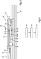
- Figure 1 shows a system with a wiper blade 30, a wiper arm 32 and a wiper device.
- the wiper device is designed as a windshield wiper device.
- the wiper device has a wiper blade adapter 12.
- the wiper device also has a wiper arm adapter 10.
- the wiper blade 30 and the wiper arm 32 can be coupled to one another via the wiper blade adapter 12 and the wiper arm adapter 10.
- the wiper arm adapter 10 and the wiper blade adapter 12 can be coupled to one another along a main extension direction, in particular can be locked to one another.
- the wiper arm adapter 10 and the wiper blade adapter 12 form side-lock adapters.
- the wiper arm adapter and the wiper blade adapter could be coupled perpendicular to a main extension direction.
- the coupling is designed to be detachable.
- the wiper blade adapter 12 comprises at least one actuating element 36, by means of which the coupling can be released.
- the wiper blade adapter 12 has at least one guide element 28.
- the guide element 28 is provided to at least partially guide the wiper arm adapter 10.
- the wiper arm adapter 10 comprises a corresponding guide element 38.
- the corresponding guide element 38 is designed to correspond to the guide element 28.
- the wiper device further comprises a spray unit 34.
- the spray unit 34 is provided for distributing and/or discharging washing water.
- the spray unit 34 comprises at least one washing water channel 42.
- the washing water channel 42 is provided for providing washing water.
- the washer water channel 42 has at least one wiper blade channel element 16.
- the wiper blade channel element 16 is arranged on the wiper blade side.
- the wiper blade channel element 16 is arranged on the wiper blade 30.
- the wiper blade channel element 16 is part of the wiper blade adapter 12.
- a wiper blade channel element could be formed separately from the wiper blade adapter.
- a wiper blade channel element could be coupled separately to a wiper blade.
- the wiper blade channel element 16 of the wiper blade adapter 12 has a main extension which is aligned at least substantially parallel to the main extension direction of the wiper blade adapter 12.
- the guide element 28 of the wiper blade adapter 12 is formed by the wiper blade channel element 16.
- the wiper blade channel element 16 of the wiper blade adapter 12 is at least partially formed in one piece onto a base body 44 of the wiper blade adapter 12.
- the base body 44 at least partially covers the wiper blade channel element 16, in particular when viewed in a direction perpendicular to a wiping surface.
- the wiper blade adapter 12 has at least one spray nozzle element 20.
- the spray nozzle element 20 is at least partially formed in one piece with the wiper blade channel element 16 of the wiper blade adapter 12.
- the spray nozzle element 20 has at least two nozzle openings.
- the spray nozzle element 20 is arranged such that the base body 44 at least partially covers the spray nozzle element 20, in particular when viewed in a direction perpendicular to a wiping surface.
- the wiper blade channel element could be connected to the base body in a different way, such as by a positive and/or non-positive connection.
- the wiper blade adapter could have further spray nozzle elements, which can in particular be formed integrally with the wiper blade channel.
- a spray nozzle could have a number of nozzle openings that differs from the number shown here.
- the wiper blade channel element 16 of the wiper blade adapter 12 is at least partially designed as a cylindrical recess 18.
- the part of the wiper blade channel element 16 designed as a recess 18 is intended to guide a wiper arm channel element 14 in the main extension direction of the wiper blade adapter 12 when coupled.
- the recess 18 has a taper 46.
- the recess 18 tapers along the main extension of the wiper blade channel element 16.
- the taper 46 is step-like. Alternatively or additionally, the taper could be continuous.
- the washer fluid channel 42 has at least one wiper arm channel element 14.
- the wiper arm channel element 14 is arranged on the wiper arm side.
- the wiper arm channel element 14 is arranged on the wiper arm 32.
- the wiper arm channel element could be formed separately from the wiper arm adapter. In this case in particular, the wiper arm channel element could be coupled separately to the wiper arm.
- the wiper arm channel element 14 has a main extension which is directed at least substantially parallel to the main extension direction of the wiper arm adapter 10.
- the corresponding guide element 38 of the wiper arm adapter 10 is formed by the wiper arm channel element 14.
- the wiper arm channel element 14 of the wiper arm adapter 10 is at least partially integrally formed on a base body 48 of the wiper arm adapter 10.
- the wiper arm channel element could be connected to the base body of the wiper arm adapter in a different way, such as by a positive and/or force fit.
- the wiper arm channel element 14 comprises at least one spray nozzle element 26.
- the spray nozzle element 26 is arranged outside the wiper blade channel element 14 in a coupled state of the wiper arm channel element 14 with the wiper blade channel element 16. Furthermore, in the coupled state of the wiper blade channel element 16 with the wiper arm channel element 14, the spray nozzle element 28 is at least partially covered by the base body 44 of the wiper blade adapter 12, in particular when viewed in a direction perpendicular to a wiping surface.
- the wiper arm channel element 14 has a sealing projection 22.
- the sealing projection 22 is intended to at least partially clamp into a wall 24 of the wiper blade channel element 16 and/or to cut into it.
- the sealing projection 22 has at least partially a conical shape.
- the wiper arm channel element 14 and the wiper blade channel element 16 are connected to one another in a watertight manner.
- the wiper arm channel element 14 is in Main extension direction of the wiper blade adapter 12 can be coupled to the wiper blade channel element 16 of the wiper blade adapter 12.
- the wiper arm channel element 14 has at least one stop element 40.
- the stop element 40 is provided to limit insertion of the wiper arm channel element 14 into the wiper blade channel element 16 along the main extension direction of the wiper blade adapter 12.
- Figure 6 shows a schematic flow chart of a method for assembling the wiper device.
- the method comprises a method step 50.
- the method step 50 is in the Figure 4 shown.
- the wiper blade adapter 12 and the wiper arm adapter 10 are aligned parallel to one another.
- the main extension direction of the wiper blade adapter 12 is aligned parallel to the main extension direction of the wiper arm adapter 10.
- the wiper blade adapter 12 and the wiper arm adapter 10 are aligned parallel such that their main extension directions coincide.
- the method comprises a further method step 52.
- step 52 in order to couple the wiper blade adapter 12 to the wiper arm adapter 10, they are moved towards one another in an assembly direction.
- the assembly direction is parallel to the main extension direction of the wiper blade adapter 12 and/or to the main extension direction of the wiper arm adapter 10.
- the wiper blade adapter 12 and the wiper arm adapter 10 are moved towards one another in a particularly continuous movement in the assembly direction.
- the guide element 28 and the corresponding guide element 38 are inserted into one another.
- the guide element 28 is formed by the wiper arm channel element 14.
- the corresponding guide element 38 is formed by the wiper blade channel element 16.
- the wiper blade adapter 12 and the wiper arm adapter 10 are locked together, in particular by clipping them into one another.
- the method comprises at least one further method step 54.
- the method step 54 is in the Figure 5
- the process step 54 takes place simultaneously with the process step 52. In the present case, these are only the Named separately for the sake of clarity.
- the wiper arm channel element 14 is automatically coupled to the wiper blade channel element 16.
- the wiper arm channel element 14 is coupled to the wiper blade channel element 16 by at least partially inserting the wiper arm channel element 14 into the wiper blade channel element 16. This preferably takes place at the same time as the introduction of the guide element 28 and the corresponding guide element 38.
- the sealing projection 22 is guided into the recess 18 along the main extension direction of the wiper arm adapter 10.
- the sealing projection 22 is clamped by means of the taper 46 of the recess 18.
- the sealing projection 22 also cuts into the wall 24 of the wiper blade channel.
Landscapes
- Engineering & Computer Science (AREA)
- Mechanical Engineering (AREA)
- Water Supply & Treatment (AREA)
- Theoretical Computer Science (AREA)
- Physics & Mathematics (AREA)
- General Engineering & Computer Science (AREA)
- General Physics & Mathematics (AREA)
- Pivots And Pivotal Connections (AREA)
- Ink Jet (AREA)
- Cleaning Implements For Floors, Carpets, Furniture, Walls, And The Like (AREA)
Description
- Es ist bereits eine Wischervorrichtung mit einem Wischarmadapter und mit einem Wischblattadapter, wobei der Wischarmadapter dazu vorgesehen ist, in Haupterstreckungsrichtung des Wischblattadapters mit dem Wischblattadapter gekoppelt zu werden, und mit einem Wischblattarmelement einer Sprüheinheit vorgeschlagen worden. Eine gattungsgemäße Wischervorrichtung ist bereits aus der
FR 3 004 685 A1 US 2012/167326 A1 offenbart ebenfalls eine Wischervorrichtung nach dem Stand der Technik. - Die Erfindung ist im beigefügten Anspruchssatz beschrieben.
- Die Erfindung geht aus von einer Wischervorrichtung, insbesondere einer Scheibenwischervorrichtung, mit einem Wischarmadapter und mit einem Wischblattadapter, wobei der Wischarmadapter dazu vorgesehen ist, in Haupterstreckungsrichtung des Wischblattadapters mit dem Wischblattadapter gekoppelt zu werden, und mit einem Wischarmkanalelement einer Sprüheinheit.
- Es wird vorgeschlagen, dass das Wischarmkanalelement dazu vorgesehen ist, in Haupterstreckungsrichtung des Wischblattadapters mit einem Wischblattkanalelement des Wischblattadapters gekoppelt zu werden.
- Durch die erfindungsgemäße Ausgestaltung der Wischervorrichtung kann eine Montage und/oder Demontage einer Sprüheinheit, vorzugsweise eines Wischblattadapters mit einem Wischarmadapter und/oder besonders bevorzugt eines Wischarms mit einem Wischblatt, vereinfacht werden. Ferner kann insbesondere sonders vorteilhaft kann eine einheitliche Gestaltung erzielt werden, wobei insbesondere die Sprüheinheit zumindest teilweise von dem Wischarm und/oder dem Wischblatt verdeckt angeordnet ist.
- Die Wischervorrichtung umfasst die Sprüheinheit.
- Unter einer "Sprüheinheit" soll insbesondere eine Einheit verstanden werden, welche an einem Sprühen von Waschwasser beteiligte Bauteile eines Wischers umfasst, wie insbesondere einen Waschwasserkanal, ein Sprühdüsenelement, eine Düsenkopplung, eine Düsenöffnung und/oder dergleichen. Unter einem "Wischarmadapter" soll in diesem Zusammenhang insbesondere ein Adapter verstanden werden, der einen Kontaktbereich zu einem Wischarmbauteil aufweist und mit dem Wischarmbauteil unverlierbar verbunden und dazu vorgesehen ist, einen Kopplungsbereich des Wischarmbauteils für eine Kopplung und/oder Kontaktierung mit einem Wischblattadapter bereitzustellen. Unter "vorgesehen" soll insbesondere speziell programmiert, ausgelegt und/oder ausgestattet verstanden werden. Darunter, dass ein Objekt zu einer bestimmten Funktion vorgesehen ist, soll insbesondere verstanden werden, dass das Objekt diese bestimmte Funktion in zumindest einem Anwendungs- und/oder Betriebszustand erfüllt und/oder ausführt. Unter einem "Wischblattadapter" soll in diesem Zusammenhang insbesondere ein Adapter verstanden werden, der einen Kontaktbereich zu einem Wischblattbauteil aufweist und mit dem Wischblattbauteil unverlierbar verbunden und dazu vorgesehen ist, einen Kopplungsbereich des Wischblattbauteils für eine Kopplung und/oder Kontaktierung mit einem Wischarmadapter bereitzustellen. Insbesondere sind der Wischblattadapter und der Wischarmadapter entlang der Haupterstreckungsrichtung des Wischblattadapters miteinander koppelbar. Unter einer "Haupterstreckungsrichtung" eines Objekts soll dabei insbesondere eine Richtung verstanden werden, welche parallel zu einer längsten Kante eines kleinsten geometrischen Quaders verläuft, welcher das Objekt gerade noch vollständig umschließt. Insbesondere soll unter "gekoppelt" vorzugsweise lösbar und besonders bevorzugt werkzeuglos lösbar verbunden verstanden werden, und zwar insbesondere kraft- und/oder formschlüssig verbunden, wie beispielsweise durch Einklemmen, Einrasten, Einschneiden oder dergleichen. Unter "kraft- und/oder formschlüssig verbunden" soll dabei insbesondere eine lösbare Verbindung verstanden werden, wobei eine Haltekraft zwischen zwei Bauteilen vorzugsweise durch einen geometrischen Eingriff der Bauteile ineinander und/oder eine Reibkraft zwischen den Bauteilen übertragen wird. Unter einem "Kanalelement" soll insbesondere ein Element verstanden werden, das zumindest teilweise zu einer Führung eines Waschwassers vorgesehen ist und das Waschwasser, in Strömungsrichtung gesehen, unmittelbar zumindest teilweise, vorzugsweise auf drei Seiten und besonders vorteilhaft vollständig umschließt. Vorzugsweise ist eine Haupterstreckung des Kanalelements parallel zur Strömungsrichtung des Waschwassers und zumindest 2-mal, insbesondere wenigstens 5-mal und vorteilhaft zumindest 10-mal länger als wenigstens eine Querschnittserstreckung des Kanalelements. Unter einem "Wischarmkanalelement" soll insbesondere ein Kanalelement verstanden werden, welches wischarmseitig angeordnet ist. Unter einem "Wischblattkanalelement" soll insbesondere ein Kanalelement verstanden werden, welches wischblattseitig angeordnet ist. Insbesondere weisen/weist der Wischblattadapter und/oder der Wischarmadapter zumindest einen Grundkörper auf, welcher in einem montierten Zustand des Wischblattadapters und/oder des Wischarmadapters zumindest teilweise, vorzugsweise zumindest zu einem Großteil und besonders bevorzugt vollständig zumindest das Wischarmkanalelement und/oder das Wischblattkanalelement überdeckt, insbesondere betrachtet in einer Richtung zumindest im Wesentlichen senkrecht zu einer Wischfläche. Unter "zumindest im Wesentlichen senkrecht" soll insbesondere eine Ausrichtung einer Richtung relativ zu einer Bezugsrichtung verstanden werden, wobei die Richtung und die Bezugsrichtung, insbesondere in einer Ebene betrachtet, einen Winkel von 90° einschließen, wobei der Winkel insbesondere eine maximale Abweichung von insbesondere kleiner als 8°, vorteilhaft kleiner als 5° und besonders vorteilhaft kleiner als 2°, aufweist. Unter dem Ausdruck "zumindest zu einem Großteil" sollen dabei insbesondere zumindest zu 55 %, vorzugsweise zumindest zu 65 %, bevorzugt zumindest zu 75 %, besonders bevorzugt zumindest zu 85 % und ganz besonders bevorzugt zumindest zu 95 % verstanden werden. Insbesondere sind das Wischarmkanalelement und das Wischblattkanalelement in einem gekoppelten Zustand wasserdicht miteinander verbunden. Das Wischarmkanalelement und das Wischblattkanalelement bilden in einem gekoppelten Zustand insbesondere zumindest teilweise, vorzugsweise zumindest zu einem Großteil einen Waschwasserkanal der Sprüheinheit aus.
- Ferner wird vorgeschlagen, dass das Wischblattkanalelement des Wischblattadapters eine Haupterstreckung aufweist, welche zumindest im Wesentlichen parallel zur Haupterstreckungsrichtung des Wischblattadapters ausgerichtet ist. Hierdurch kann vorteilhaft eine Montage weiter vereinfacht werden. Insbesondere kann ein Bauraum eingespart werden. Unter einer "Haupterstreckung" eines Objekts soll dabei insbesondere eine längste Erstreckung eines kleinsten geometrischen Quaders verstanden werden, welcher das Objekt gerade noch vollständig umschließt. Unter "zumindest im Wesentlichen parallel" soll insbesondere eine Ausrichtung einer Richtung relativ zu einer Bezugsrichtung verstanden werden, wobei die Richtung und die Bezugsrichtung, insbesondere in einer Ebene betrachtet, einen Winkel von 0° einschließen, wobei der Winkel insbesondere eine maximale Abweichung von insbesondere kleiner als 8°, vorteilhaft kleiner als 5° und besonders vorteilhaft kleiner als 2°, aufweist. Ferner weist insbesondere das Wischarmkanalelement eine Haupterstreckung auf, welche zumindest im Wesentlichen parallel zur Haupterstreckungsrichtung des Wischarmadapters ausgerichtet ist. Insbesondere wenn der Wischarmadapter und der Wischblattadapter zueinander zumindest im Wesentlichen parallel ausgerichtet sind, sind auch das Wischarmkanalelement und das Wischblattkanalelement zumindest im Wesentlichen parallel zueinander angeordnet.
- Ferner wird vorgeschlagen, dass das Wischblattkanalelement des Wischblattadapters zumindest teilweise einstückig an einen Grundkörper des Wischblattadapters angeformt ist. Hierdurch kann vorteilhaft eine Montage weiter vereinfacht werden. Ferner können insbesondere zusätzliche Bauteile vermieden werden. Unter "zumindest teilweise einstückig" soll in diesem Zusammenhang insbesondere verstanden werden, dass ein Objekt zumindest ein Bauteil aufweist, welches einstückig mit zumindest einem weiteren Bauteil des Objekts verbunden ist. Unter "einstückig" soll insbesondere zumindest stoffschlüssig verbunden verstanden werden, beispielsweise durch einen Schweißprozess, einen Klebeprozess, einen Anspritzprozess und/oder einen anderen, dem Fachmann als sinnvoll erscheinenden Prozess. Vorteilhaft soll unter einstückig auch einteilig verstanden werden. Unter "einteilig" soll insbesondere in einem Stück geformt verstanden werden, wie beispielsweise durch eine Herstellung aus einem Guss und/oder durch eine Herstellung in einem Ein- oder Mehrkomponentenspritzverfahren und vorteilhaft aus einem einzelnen Rohling. Insbesondere kann das Wischarmkanalelement des Wischarmadapters zumindest teilweise einstückig an einen Grundkörper des Wischarmadapters angeformt sein. Alternativ könnte das Wischarmkanalelement auch separat von dem Wischarmadapter ausgebildet sein. Insbesondere ist das Wischarmkanalelement separat mit einem Wischarm und/oder einem Wischarmadapter koppelbar.
- Ferner wird vorgeschlagen, dass das Wischblattkanalelement des Wischblattadapters zumindest teilweise als zylinderförmige Aussparung ausgebildet und dazu vorgesehen ist, das Wischarmkanalelement zu einer Kopplung in Haupterstreckungsrichtung des Wischblattadapters zu führen. Hierdurch kann vorteilhaft eine Montage weiter vereinfacht werden. Insbesondere kann eine passgenaue Montage erzielt werden. Insbesondere weist die Aussparung eine Verjüngung, vorzugsweise entlang der Haupterstreckung des Wischblattkanalelements auf. Die Verjüngung kann dabei insbesondere kontinuierlich und/oder stufenhaft ausgebildet sein.
- Erfindungsgemäß weist der Wischblattadapter zumindest ein Sprühdüsenelement auf, welches zumindest teilweise einstückig mit dem Wischblattkanalelement des Wischblattadapters ausgebildet ist. Hierdurch kann eine flexible Bereitstellung von Wischwasser erzielt werden. Insbesondere kann das Wischblattadapterelement zumindest zwei und besonders bevorzugt mehrere Sprühdüsenelemente umfassen. Erfindungsgemäß ist das Sprühdüsenelement von dem Grundkörper des Wischblattadapters zumindest einem Großteil und besonders bevorzugt vollständig überdeckt, insbesondere betrachtet in einer Richtung senkrecht zu einer Wischfläche. Ferner kann der Wischblattadapter weitere Sprühdüsenelemente aufweisen. Vorzugsweise weist das Sprühdüsenelement zumindest zwei Düsenöffnungen auf, welche vorzugsweise in zwei verschiedene Richtungen gerichtet sind.
- Ferner wird vorgeschlagen, dass das Wischarmkanalelement einen Dichtungsvorsprung aufweist, welcher dazu vorgesehen ist, sich in eine Wandung des Wischblattkanalelements zumindest teilweise einzuklemmen. Hierdurch kann vorteilhaft eine Dichtwirkung verbessert werden. Ferner kann eine Kopplung besonders gesichert werden. Insbesondere schneidet der Dichtungsvorsprung zumindest teilweise in die Wandung ein. Insbesondere schneidet der Dichtungsvorsprung in einem montierten Zustand des Wischblattkanals mit dem Wischarmkanal in die Wandung im Bereich der Aussparung des Wischblattadapters ein. Besonders bevorzugt weist der Dichtungsvorsprung zumindest teilweise eine Konusform auf. Hierdurch kann vorteilhaft eine Montage weiter vereinfacht werden, da ein derartiger konusförmiger Dichtungsvorsprung leicht in die Aussparung des Wischblattadapters eingeführt werden kann. Ferner verhindert die Konusform vorteilhaft ein Herausziehen des Dichtungsvorsprungs aus der Aussparung. Zudem kann insbesondere eine besonders vorteilhafte wasserdichte Dichtwirkung erzielt werden.
- Ferner wird vorgeschlagen, dass das Wischarmkanalelement zumindest ein Sprühdüsenelement aufweist, welches in einem montierten Zustand außerhalb des Wischblattkanalelements angeordnet ist. Hierdurch kann vorteilhaft eine Flexibilität einer Bereitstellung von Wischwasser weiter verbessert werden. Insbesondere ist das Sprühdüsenelement außerhalb eines kleinsten gedachten Quaders angeordnet, welcher das Wischblattkanalelement gerade noch vollständig umschließt. Vorzugsweise ist das Sprühdüsenelement von dem Grundkörper des Wischblattadapters zumindest teilweise, vorzugsweise zumindest zu einem Großteil und besonders bevorzugt vollständig überdeckt, insbesondere betrachtet in einer Richtung senkrecht zu einer Wischfläche.
- Ferner wird vorgeschlagen, dass der Wischblattadapter wenigstens ein Führungselement aufweist, welches bei einer Kopplung mit dem Wischarmadapter dazu vorgesehen ist, den Wischarmadapter zumindest teilweise zu führen. Hierdurch kann vorteilhaft eine Montage vereinfacht werden. Vorzugsweise bildet das Wischblattkanalelement das Führungselement aus. Ferner weist der Wischarmadapter wenigstens ein korrespondierendes Führungselement auf, welches korrespondierend zu dem Führungselement des Wischblattadapters ausgebildet ist. Vorzugsweise ist das korrespondierende Führungselement von dem Wischarmkanalelement ausgebildet.
- In einem weiteren, nicht beanspruchten Aspekt der Erfindung wird ein Verfahren zur Montage einer Wischervorrichtung, insbesondere der zuvor genannten Wischervorrichtung, vorgeschlagen, bei welchem ein Wischarmadapter mit einem Wischblattadapter in Haupterstreckungsrichtung des Wischblattadapters gekoppelt wird, wobei in zumindest einem Verfahrensschritt ein Wischarmkanalelement einer Sprüheinheit in Haupterstreckungsrichtung des Wischblattadapters mit einem Wischblattkanalelement des Wischblattadapters gekoppelt wird. Durch die erfindungsgemäße Ausgestaltung des Verfahrens kann eine Montage und/oder Demontage einer Sprüheinheit, vorzugsweise eines Wischblattadapters mit einem Wischarmadapter und/oder besonders bevorzugt eines Wischarms mit einem Wischblatt, vereinfacht werden. Ferner kann insbesondere eine dichte und wieder lösbare Verbindung der Sprüheinheit erzielt werden. Besonders vorteilhaft kann eine einheitliche Gestaltung erzielt werden, wobei insbesondere die Sprüheinheit zumindest teilweise von dem Wischarm und/oder dem Wischblatt verdeckt angeordnet ist. Insbesondere werden der Wischblattadapter und der Wischarmadapter bei einer Montage entlang ihrer Haupterstreckungsrichtungen parallel und vorzugsweise zusammenfallend angeordnet. Besonders bevorzugt fallen die jeweiligen Haupterstreckungsrichtungen des Wischblattadapters und des Wischarmadapters mit einer Montagerichtung zusammen. Vorzugsweise werden der Wischblattadapter und der Wischarmadapter durch Aufeinanderzubewegen, insbesondere in Montagerichtung, ineinander eingeklipst.
- Weiterhin wird vorgeschlagen, dass in dem Verfahrensschritt das Wischarmkanalelement automatisch mit dem Wischblattkanalelement gekoppelt wird, wenn der Wischarmadapter mit dem Wischblattadapter gekoppelt wird. Hierdurch kann eine Montage weiter verbessert werden. Darunter, dass eine Kopplung automatisch mit einer weiteren Kopplung stattfindet, soll hier insbesondere verstanden werden, dass diese durch eine, vorzugsweise eine einzige Bewegung in eine gleiche Richtung, insbesondere entlang der jeweiligen Haupterstreckungsrichtung und vorzugsweise entlang der Montagerichtung, erfolgt.
- Weitere Vorteile ergeben sich aus der folgenden Zeichnungsbeschreibung. In der Zeichnung ist ein Ausführungsbeispiel der Erfindung dargestellt. Die Zeichnungen, die Beschreibung und die Ansprüche enthalten zahlreiche Merkmale in Kombination. Der Fachmann wird die Merkmale zweckmäßigerweise auch einzeln betrachten und zu sinnvollen weiteren Kombinationen zusammenfassen.
- Es zeigen:
- Fig. 1
- ein System mit einem Wischblatt, einem Wischarm und einer Wischervorrichtung in einer schematischen Draufsicht,
- Fig. 2
- einen Teil der Wischervorrichtung mit einem Wischarmadapter und einem Wischblattadapter in einer schematischen Draufsicht,
- Fig. 3
- einen Teil der Wischervorrichtung mit dem Wischarmadapter und dem Wischblattadapter in einer schematischen Seitenansicht,
- Fig. 4
- einen Teil der Wischervorrichtung mit einem Wischarmkanalelement und ein Wischblattkanalelement in einer halbgeschnittenen Darstellung in einem voneinander getrennten Zustand,
- Fig. 5
- einen Teil der Wischervorrichtung mit einem Wischarmkanalelement und ein Wischblattkanalelement in einer halbgeschnittenen Darstellung in einem gekoppelten Zustand und
- Fig. 6
- einen schematischen Verfahrensablauf eines Verfahrens zur Montage der Wischervorrichtung.
-
Figur 1 zeigt ein System mit einem Wischblatt 30, einem Wischarm 32 und mit einer Wischervorrichtung. Die Wischervorrichtung ist im vorliegenden Fall als eine Scheibenwischervorrichtung ausgebildet. - In den
Figuren 2 bis 5 ist die Wischervorrichtung in verschiedenen Darstellungen gezeigt. Die Wischervorrichtung weist einen Wischblattadapter 12 auf. Ferner weist die Wischervorrichtung einen Wischarmadapter 10 auf. Über den Wischblattadapter 12 und den Wischarmadapter 10 sind das Wischblatt 30 und der Wischarm 32 miteinander koppelbar. Im vorliegenden Fall sind zur Kopplung des Wischarms 32 mit dem Wischblatt 30 der Wischarmadapter 10 und der Wischblattadapter 12 entlang einer Haupterstreckungsrichtung miteinander koppelbar, insbesondere miteinander verrastbar. Der Wischarmadapter 10 und der Wischblattadapter 12 bilden Side-Lock-Adapter aus. Alternativ oder zusätzlich könnten zur Kopplung des Wischarms mit dem Wischblatt der Wischarmadapter und der Wischblattadapter senkrecht einer Haupterstreckungsrichtung koppelbar sein. Die Kopplung ist lösbar ausgebildet. Im vorliegenden Fall umfasst der Wischblattadapter 12 zumindest ein Betätigungselement 36, mittels welchem die Kopplung lösbar ist. - Zur Kopplung weist der Wischblattadapter 12 wenigstens ein Führungselement 28 auf. Das Führungselement 28 ist bei einer Kopplung dazu vorgesehen, mit dem Wischarmadapter 10 diesen zumindest teilweise zu führen. Der Wischarmadapter 10 umfasst ein korrespondierendes Führungselement 38. Das korrespondierende Führungselement 38 ist korrespondierend zu dem Führungselement 28 ausgebildet.
- Ferner weist die Wischervorrichtung eine Sprüheinheit 34 auf. Die Sprüheinheit 34 ist zu einer Verteilung und/oder einem Auslass von Waschwasser vorgesehen. Die Sprüheinheit 34 umfasst zumindest einen Waschwasserkanal 42. Der Waschwasserkanal 42 ist zur Bereitstellung von Waschwasser vorgesehen.
- Der Waschwasserkanal 42 weist zumindest ein Wischblattkanalelement 16 auf. Das Wischblattkanalelement 16 ist wischblattseitig angeordnet. Das Wischblattkanalelement 16 ist an dem Wischblatt 30 angeordnet. Im vorliegenden Fall ist das Wischblattkanalelement 16 Teil des Wischblattadapters 12. Alternativ könnte ein Wischblattkanalelement separat von dem Wischblattadapter ausgebildet sein. Insbesondere für diesen Fall könnte ein Wischblattkanalelement separat mit einem Wischblatt koppelbar sein.
- Das Wischblattkanalelement 16 des Wischblattadapters 12 weist eine Haupterstreckung auf, welche zumindest im Wesentlichen parallel zur Haupterstreckungsrichtung des Wischblattadapters 12 ausgerichtet ist. Das Führungselement 28 des Wischblattadapters 12 ist von dem Wischblattkanalelement 16 ausgebildet. Im vorliegenden Fall ist das Wischblattkanalelement 16 des Wischblattadapters 12 zumindest teilweise einstückig an einen Grundkörper 44 des Wischblattadapters 12 angeformt. Der Grundkörper 44 überdeckt das Wischblattkanalelement 16 zumindest teilweise, insbesondere betrachtet in einer Richtung senkrecht zu einer Wischfläche. Der Wischblattadapter 12 weist zumindest ein Sprühdüsenelement 20 auf. Das Sprühdüsenelement 20 ist zumindest teilweise einstückig mit dem Wischblattkanalelement 16 des Wischblattadapters 12 ausgebildet. Das Sprühdüsenelement 20 weist zumindest zwei Düsenöffnungen auf. Das Sprühdüsenelement 20 ist derart angeordnet, dass der Grundkörper 44 das Sprühdüsenelement 20 zumindest teilweise überdeckt, und zwar insbesondere betrachtet in einer Richtung senkrecht zu einer Wischfläche. Alternativ könnte das Wischblattkanalelement auf eine andere Art und Weise mit dem Grundkörper verbunden sein, wie beispielsweise durch einen Form- und/oder Kraftschluss. Ferner könnte der Wischblattadapter über weitere Sprühdüsenelemente verfügen, welche insbesondere einstückig mit dem Wischblattkanal ausgebildet sein können. Ferner könnte eine Sprühdüse eine von der hier dargestellten Anzahl abweichende Anzahl an Düsenöffnungen aufweisen.
- Das Wischblattkanalelement 16 des Wischblattadapters 12 ist zumindest teilweise als zylinderförmige Aussparung 18 ausgebildet. Das als Aussparung 18 ausgebildete Teil des Wischblattkanalelements 16 ist dazu vorgesehen, bei einer Kopplung ein Wischarmkanalelement 14 in Haupterstreckungsrichtung des Wischblattadapters 12 zu führen. Die Aussparung 18 weist eine Verjüngung 46 auf. Die Aussparung 18 verjüngt sich entlang der Haupterstreckung des Wischblattkanalelements 16. Im vorliegenden Fall ist die Verjüngung 46 stufenartig ausgebildet. Alternativ oder zusätzlich könnte die Verjüngung kontinuierlich ausgebildet sein.
- Der Waschwasserkanal 42 weist zumindest ein Wischarmkanalelement 14 auf. Das Wischarmkanalelement 14 ist wischarmseitig angeordnet. Das Wischarmkanalelement 14 ist an dem Wischarm 32 angeordnet. Alternativ könnte das Wischarmkanalelement separat von dem Wischarmadapter ausgebildet sein. Insbesondere für diesen Fall könnte das Wischarmkanalelement separat mit dem Wischarm koppelbar sein.
- Das Wischarmkanalelement 14 weist eine Haupterstreckung auf, welche zumindest im Wesentlichen parallel zur Haupterstreckungsrichtung des Wischarmadapters 10 gerichtet ist. Das korrespondierende Führungselement 38 des Wischarmadapters 10 ist von dem Wischarmkanalelement 14 ausgebildet. Im vorliegenden Fall ist das Wischarmkanalelement 14 des Wischarmadapters 10 zumindest teilweise einstückig an einem Grundkörper 48 des Wischarmadapters 10 angeformt. Alternativ könnte das Wischarmkanalelement auf eine andere Art und Weise mit dem Grundkörper des Wischarmadapters verbunden sein, wie beispielsweise durch einen Form- und/oder Kraftschluss.
- Das Wischarmkanalelement 14 umfasst zumindest ein Sprühdüsenelement 26. Das Sprühdüsenelement 26 ist in einem gekoppelten Zustand des Wischarmkanalelements 14 mit dem Wischblattkanalelement 16 außerhalb des Wischblattkanalelements 14 angeordnet. Ferner ist in dem gekoppelten Zustand des Wischblattkanalelements 16 mit dem Wischarmkanalelement 14 das Sprühdüsenelement 28 zumindest teilweise, von dem Grundkörper 44 des Wischblattadapters 12 überdeckt, und zwar insbesondere betrachtet in einer Richtung senkrecht zu einer Wischfläche.
- Das Wischarmkanalelement 14 weist einen Dichtungsvorsprung 22 auf. Der Dichtungsvorsprung 22 ist dazu vorgesehen, sich in einer Wandung 24 des Wischblattkanalelements 16 zumindest teilweise zu verklemmen und/oder in diese einzuschneiden. Der Dichtungsvorsprung 22 weist zumindest teilweise eine Konusform auf. Das Wischarmkanalelement 14 und das Wischblattkanalelement 16 sind wasserdicht miteinander verbunden. Das Wischarmkanalelement 14 ist in Haupterstreckungsrichtung des Wischblattadapters 12 mit dem Wischblattkanalelement 16 des Wischblattadapters 12 koppelbar. Das Wischarmkanalelement 14 weist zumindest ein Anschlagselement 40 auf. Das Anschlagselement 40 ist dazu vorgesehen ein Einführen des Wischarmkanalelements 14 in das Wischblattkanalelement 16 entlang der Haupterstreckungsrichtung des Wischblattadapters 12 zu beschränken.
-
Figur 6 zeigt einen schematischen Ablaufplan eines Verfahrens zur Montage der Wischervorrichtung. - Das Verfahren umfasst einen Verfahrensschritt 50. Der Verfahrensschritt 50 ist in der
Figur 4 dargestellt. In dem Verfahrensschritt 50 werden der Wischblattadapter 12 und der Wischarmadapter 10 zueinander parallel ausgerichtet. Dazu wird die Haupterstreckungsrichtung des Wischblattadapters 12 parallel zur Haupterstreckungsrichtung des Wischarmadapters 10 ausgerichtet. Ferner werden der Wischblattadapter 12 und der Wischarmadapter 10 derart parallel ausgerichtet, dass deren Haupterstreckungsrichtungen zusammenfallen. - Das Verfahren umfasst einen weiteren Verfahrensschritt 52. In dem Verfahrensschritt 52 werden zur Kopplung des Wischblattadapters 12 mit dem Wischarmadapter 10 diese in einer Montagerichtung aufeinanderzubewegt. Die Montagerichtung ist dabei parallel zur Haupterstreckungsrichtung des Wischblattadapters 12 und/oder zur Haupterstreckungsrichtung des Wischarmadapters 10. Dazu werden der Wischblattadapter 12 und der Wischarmadapter 10 in einer insbesondere kontinuierlichen Bewegung in Montagerichtung aufeinanderzubewegt. Dabei werden das Führungselement 28 und das korrespondierende Führungselement 38 ineinander eingeführt. Das Führungselement 28 ist von dem Wischarmkanalelement 14 ausgebildet. Das korrespondierende Führungselement 38 ist von dem Wischblattkanalelement 16 ausgebildet. Der Wischblattadapter 12 und der Wischarmadapter 10 werden miteinander verrastet, und zwar insbesondere durch ineinander Einklipsen.
- Das Verfahren umfasst zumindest einen weiteren Verfahrensschritt 54. Der Verfahrensschritt 54 ist in der
Figur 5 dargestellt. Der Verfahrensschritt 54 erfolgt gleichzeitig mit dem Verfahrensschritt 52. Diese sind im vorliegenden Fall nur der Übersichtlichkeit halber separat voneinander benannt. In dem weiteren Verfahrensschritt 54 erfolgt bei einer Kopplung des Wischarmadapters 10 mit dem Wischblattadapter 12 automatisch eine Kopplung des Wischarmkanalelements 14 mit dem Wischblattkanalelement 16. Das Wischarmkanalelement 14 wird mit dem Wischblattkanalelement 16 gekoppelt, indem das Wischarmkanalelement 14 zumindest teilweise in das Wischblattkanalelement 16 eingeführt wird. Dies erfolgt vorzugsweise gleichzeitig mit der Einführung des Führungselements 28 und des korrespondierenden Führungselements 38. Der Dichtungsvorsprung 22 wird entlang der Haupterstreckungsrichtung des Wischarmadapters 10 in die Aussparung 18 geführt. Mittels der Verjüngung 46 der Aussparung 18 verklemmt sich der Dichtungsvorsprung 22. Der Dichtungsvorsprung 22 schneidet ferner in die Wandung 24 des Wischblattkanals ein.
Claims (9)
- Wischervorrichtung, insbesondere Scheibenwischervorrichtung, mit einem Wischarmadapter (10) und mit einem Wischblattadapter (12), und mit einem Wischarmkanalelement (14) einer Sprüheinheit (34), wobei der Wischarmadapter (10) dazu vorgesehen ist, in der Haupterstreckungsrichtung des Wischblattadapters (12) mit dem Wischblattadapter (12) gekoppelt zu werden, und wobei das Wischarmkanalelement (14) dazu vorgesehen ist, in Haupterstreckungsrichtung des Wischblattadapters (12) mit einem Wischblattkanalelement (16) des Wischblattadapters (12) gekoppelt zu werden, wobei die Haupterstreckungsrichtung des Wischblattadapters (12) parallel zu einer längsten Kante eines kleinsten geometrischen Quaders verläuft, welcher den Wischblattadapter (12) gerade noch vollständig umschließt , dadurch gekennzeichnet, dass der Wischblattadapter (12) zumindest ein Sprühdüsenelement (20) aufweist, welches zumindest teilweise einstückig mit dem Wischblattkanalelement (16) ausgebildet ist, wobei das Sprühdüsenelement (20), betrachtet in einer Richtung senkrecht zu einer Wischfläche, von einem Grundkörper (44) des Wischblattadapters (12) zumindest zu einem Großteil überdeckt ist.
- Wischervorrichtung nach Anspruch 1, dadurch gekennzeichnet, dass das Wischblattkanalelement (16) eine Haupterstreckung aufweist, welche zumindest im Wesentlichen parallel zur Haupterstreckungsrichtung des Wischblattadapters (12) ausgerichtet ist.
- Wischervorrichtung nach Anspruch 1 oder 2, dadurch gekennzeichnet, dass das Wischblattkanalelement (16) zumindest teilweise einstückig an den Grundkörper (44) des Wischblattadapters (12) angeformt ist.
- Wischervorrichtung nach Anspruch 3, dadurch gekennzeichnet, dass das Wischblattkanalelement (16) zumindest teilweise als zylinderförmige Aussparung (18) ausgebildet und dazu vorgesehen ist, das Wischarmkanalelement (14) zu einer Kopplung in Haupterstreckungsrichtung des Wischblattadapters (12) zu führen.
- Wischervorrichtung nach einem der vorhergehenden Ansprüche, dadurch gekennzeichnet, dass das Wischarmkanalelement (14) einen Dichtungsvorsprung (22) aufweist, welcher dazu vorgesehen ist, sich in eine Wandung (24) des Wischblattkanalelements (16) zumindest teilweise einzuklemmen.
- Wischervorrichtung nach Anspruch 5, dadurch gekennzeichnet, dass der Dichtungsvorsprung (22) zumindest teilweise eine Konusform aufweist.
- Wischervorrichtung nach einem der vorhergehenden Ansprüche, dadurch gekennzeichnet, dass das Wischarmkanalelement (14) zumindest ein Sprühdüsenelement (26) aufweist, welches in einem montierten Zustand außerhalb des Wischblattkanalelements (16) angeordnet ist.
- Wischervorrichtung nach einem der vorhergehenden Ansprüche, dadurch gekennzeichnet, dass der Wischblattadapter (12) wenigstens ein Führungselement (28) aufweist, welches bei einer Kopplung mit dem Wischarmadapter (10) dazu vorgesehen ist, den Wischarmadapter (10) zumindest teilweise zu führen.
- System mit einem Wischblatt (30), mit einem Wischarm (32) und mit einer Wischervorrichtung nach einem der Ansprüche 1 bis 8.
Applications Claiming Priority (2)
| Application Number | Priority Date | Filing Date | Title |
|---|---|---|---|
| DE102018202714.5A DE102018202714A1 (de) | 2018-02-22 | 2018-02-22 | Wischervorrichtung |
| PCT/EP2019/050725 WO2019161990A1 (de) | 2018-02-22 | 2019-01-12 | Wischervorrichtung |
Publications (2)
| Publication Number | Publication Date |
|---|---|
| EP3755586A1 EP3755586A1 (de) | 2020-12-30 |
| EP3755586B1 true EP3755586B1 (de) | 2024-06-26 |
Family
ID=65023907
Family Applications (1)
| Application Number | Title | Priority Date | Filing Date |
|---|---|---|---|
| EP19700586.1A Active EP3755586B1 (de) | 2018-02-22 | 2019-01-12 | Wischervorrichtung |
Country Status (5)
| Country | Link |
|---|---|
| US (1) | US11772609B2 (de) |
| EP (1) | EP3755586B1 (de) |
| CN (1) | CN111727139B (de) |
| DE (2) | DE202018006068U1 (de) |
| WO (1) | WO2019161990A1 (de) |
Families Citing this family (4)
| Publication number | Priority date | Publication date | Assignee | Title |
|---|---|---|---|---|
| CN113365886B (zh) | 2018-12-19 | 2024-05-10 | 特瑞科比利时股份公司 | 平片型风挡刮水器装置 |
| EP3962787B1 (de) | 2019-04-30 | 2024-08-07 | Trico Belgium S.A. | Scheibenwischervorrichtung mit flachen wischerblättern |
| US20220176913A1 (en) * | 2019-04-30 | 2022-06-09 | Trico Belgium S.a. | A windscreen wiper device of the flat blade type |
| EP4126603A1 (de) | 2020-03-30 | 2023-02-08 | Trico Belgium S.A. | Scheibenwischervorrichtung mit flachem blatt |
Citations (2)
| Publication number | Priority date | Publication date | Assignee | Title |
|---|---|---|---|---|
| DE102013209196A1 (de) * | 2013-05-17 | 2014-11-20 | Robert Bosch Gmbh | Wischvorrichtung |
| FR3015398A1 (fr) * | 2013-12-20 | 2015-06-26 | Valeo Systemes Dessuyage | Balai d'essuie-glace comprenant un moyen de projection de liquide |
Family Cites Families (8)
| Publication number | Priority date | Publication date | Assignee | Title |
|---|---|---|---|---|
| US9889823B2 (en) * | 2010-12-02 | 2018-02-13 | Valeo Systèmes d'Essuyage | Hydraulic connector for a windshield wiper blade having a retractable button |
| DE102010056366A1 (de) * | 2010-12-29 | 2012-07-05 | Valeo Systèmes d'Essuyage | Wischblatt zum Reinigen von Scheiben von Kraftfahrzeugen und Wischarm |
| FR3004685B1 (fr) * | 2013-04-17 | 2016-02-26 | Peugeot Citroen Automobiles Sa | Dispositif d'essuie glace |
| EP2815932B1 (de) * | 2013-06-19 | 2019-04-10 | Valeo Systèmes d'Essuyage | Wischerblatt zum Reinigen von Fahrzeugscheiben, Wischerarm für ein Wischerblatt und Wischervorrichtung |
| DE102014017602A1 (de) * | 2014-11-27 | 2015-06-18 | Daimler Ag | Wischerblatt für eine Scheibenwischanlage eines Kraftwagens und Scheibenwischanlage |
| DE102015114922A1 (de) * | 2015-09-07 | 2017-03-09 | Valeo Systèmes d'Essuyage | Wischvorrichtung zum Reinigen von Fahrzeugscheiben |
| DE102015224609A1 (de) * | 2015-12-08 | 2017-06-08 | Robert Bosch Gmbh | Adapter für einen Wischarm sowie solch ein Wischarm als auch ein Kraftfahrzeug mit einem Wischarm und einer Wischanlage und die Wischanlage selbst |
| DE102015226527A1 (de) | 2015-12-22 | 2017-06-22 | Robert Bosch Gmbh | Wischervorrichtung |
-
2018
- 2018-02-22 DE DE202018006068.2U patent/DE202018006068U1/de active Active
- 2018-02-22 DE DE102018202714.5A patent/DE102018202714A1/de active Pending
-
2019
- 2019-01-12 CN CN201980014836.8A patent/CN111727139B/zh active Active
- 2019-01-12 WO PCT/EP2019/050725 patent/WO2019161990A1/de not_active Ceased
- 2019-01-12 US US16/975,016 patent/US11772609B2/en active Active
- 2019-01-12 EP EP19700586.1A patent/EP3755586B1/de active Active
Patent Citations (2)
| Publication number | Priority date | Publication date | Assignee | Title |
|---|---|---|---|---|
| DE102013209196A1 (de) * | 2013-05-17 | 2014-11-20 | Robert Bosch Gmbh | Wischvorrichtung |
| FR3015398A1 (fr) * | 2013-12-20 | 2015-06-26 | Valeo Systemes Dessuyage | Balai d'essuie-glace comprenant un moyen de projection de liquide |
Also Published As
| Publication number | Publication date |
|---|---|
| US20210070256A1 (en) | 2021-03-11 |
| CN111727139B (zh) | 2023-10-13 |
| EP3755586A1 (de) | 2020-12-30 |
| DE102018202714A1 (de) | 2019-08-22 |
| US11772609B2 (en) | 2023-10-03 |
| WO2019161990A1 (de) | 2019-08-29 |
| DE202018006068U1 (de) | 2019-03-18 |
| CN111727139A (zh) | 2020-09-29 |
Similar Documents
| Publication | Publication Date | Title |
|---|---|---|
| EP3755586B1 (de) | Wischervorrichtung | |
| DE69816935T2 (de) | Manschette für ein Rohrelement | |
| EP2658759B1 (de) | Wischblattadapter, insbesondere für eine kraftfahrzeugscheibenwischvorrichtung | |
| EP2658755B1 (de) | Wischblattadapter, insbesondere für eine kraftfahrzeugwischvorrichtung | |
| EP2697103B1 (de) | Wischblattadaptervorrichtung | |
| EP3233591B1 (de) | Adaptervorrichtung | |
| EP3475128B1 (de) | Wischblattadaptervorrichtung | |
| EP2861467B1 (de) | Wischblattadaptersystem | |
| EP3727959B1 (de) | Wischarmvorrichtung | |
| DE102011001689A1 (de) | Wischblatt sowie Wischarm zum Reinigen von Fahrzeugscheiben | |
| EP3237269B1 (de) | Seitenspoiler für ein kraftfahrzeug | |
| EP3863895B1 (de) | Anbauteil für einen wischerarm | |
| EP2683582A1 (de) | Wischblattadapter, insbesondere für eine kraftfahrzeugwischvorrichtung | |
| EP3230133B1 (de) | Wischarmvorrichtung mit einer waschwasserdüse | |
| DE102013103279A1 (de) | Wischarm für eine Scheibenwischanlage eines Kraftfahrzeugs, Wischblatt und Wischeinrichtung | |
| DE102014114688A1 (de) | Wischblatt und Wischvorrichtung zum Reinigen von Fahrzeugscheiben | |
| EP2651703B1 (de) | Scheibenwischvorrichtung für ein kraftfahrzeug | |
| EP3911543B1 (de) | Wischblattvorrichtung | |
| EP2861470B1 (de) | Wischblattadaptersystem | |
| EP3392098B1 (de) | Wischervorrichtung | |
| WO2017167810A1 (de) | Sprühvorrichtung für ein wischblatt | |
| DE2352777B2 (de) | Loesbare verbindung zwischen dem wischblatt und dem wischarm einer scheibenwischanlage | |
| EP0738636A1 (de) | Waschdüse für eine Scheibenwaschanlage eines Fahrzeuges | |
| EP3101318A1 (de) | Ventilmodul | |
| DE102022200473A1 (de) | Wischervorrichtung, Wischblatt und Wischarmeinheit |
Legal Events
| Date | Code | Title | Description |
|---|---|---|---|
| STAA | Information on the status of an ep patent application or granted ep patent |
Free format text: STATUS: UNKNOWN |
|
| STAA | Information on the status of an ep patent application or granted ep patent |
Free format text: STATUS: THE INTERNATIONAL PUBLICATION HAS BEEN MADE |
|
| PUAI | Public reference made under article 153(3) epc to a published international application that has entered the european phase |
Free format text: ORIGINAL CODE: 0009012 |
|
| STAA | Information on the status of an ep patent application or granted ep patent |
Free format text: STATUS: REQUEST FOR EXAMINATION WAS MADE |
|
| 17P | Request for examination filed |
Effective date: 20200922 |
|
| AK | Designated contracting states |
Kind code of ref document: A1 Designated state(s): AL AT BE BG CH CY CZ DE DK EE ES FI FR GB GR HR HU IE IS IT LI LT LU LV MC MK MT NL NO PL PT RO RS SE SI SK SM TR |
|
| AX | Request for extension of the european patent |
Extension state: BA ME |
|
| DAV | Request for validation of the european patent (deleted) | ||
| DAX | Request for extension of the european patent (deleted) | ||
| STAA | Information on the status of an ep patent application or granted ep patent |
Free format text: STATUS: EXAMINATION IS IN PROGRESS |
|
| 17Q | First examination report despatched |
Effective date: 20210819 |
|
| GRAP | Despatch of communication of intention to grant a patent |
Free format text: ORIGINAL CODE: EPIDOSNIGR1 |
|
| STAA | Information on the status of an ep patent application or granted ep patent |
Free format text: STATUS: GRANT OF PATENT IS INTENDED |
|
| INTG | Intention to grant announced |
Effective date: 20240116 |
|
| GRAS | Grant fee paid |
Free format text: ORIGINAL CODE: EPIDOSNIGR3 |
|
| GRAA | (expected) grant |
Free format text: ORIGINAL CODE: 0009210 |
|
| STAA | Information on the status of an ep patent application or granted ep patent |
Free format text: STATUS: THE PATENT HAS BEEN GRANTED |
|
| AK | Designated contracting states |
Kind code of ref document: B1 Designated state(s): AL AT BE BG CH CY CZ DE DK EE ES FI FR GB GR HR HU IE IS IT LI LT LU LV MC MK MT NL NO PL PT RO RS SE SI SK SM TR |
|
| REG | Reference to a national code |
Ref country code: GB Ref legal event code: FG4D Free format text: NOT ENGLISH |
|
| REG | Reference to a national code |
Ref country code: CH Ref legal event code: EP |
|
| REG | Reference to a national code |
Ref country code: DE Ref legal event code: R096 Ref document number: 502019011512 Country of ref document: DE |
|
| PG25 | Lapsed in a contracting state [announced via postgrant information from national office to epo] |
Ref country code: BG Free format text: LAPSE BECAUSE OF FAILURE TO SUBMIT A TRANSLATION OF THE DESCRIPTION OR TO PAY THE FEE WITHIN THE PRESCRIBED TIME-LIMIT Effective date: 20240626 |
|
| PG25 | Lapsed in a contracting state [announced via postgrant information from national office to epo] |
Ref country code: HR Free format text: LAPSE BECAUSE OF FAILURE TO SUBMIT A TRANSLATION OF THE DESCRIPTION OR TO PAY THE FEE WITHIN THE PRESCRIBED TIME-LIMIT Effective date: 20240626 Ref country code: FI Free format text: LAPSE BECAUSE OF FAILURE TO SUBMIT A TRANSLATION OF THE DESCRIPTION OR TO PAY THE FEE WITHIN THE PRESCRIBED TIME-LIMIT Effective date: 20240626 |
|
| REG | Reference to a national code |
Ref country code: LT Ref legal event code: MG9D |
|
| PG25 | Lapsed in a contracting state [announced via postgrant information from national office to epo] |
Ref country code: GR Free format text: LAPSE BECAUSE OF FAILURE TO SUBMIT A TRANSLATION OF THE DESCRIPTION OR TO PAY THE FEE WITHIN THE PRESCRIBED TIME-LIMIT Effective date: 20240927 |
|
| PG25 | Lapsed in a contracting state [announced via postgrant information from national office to epo] |
Ref country code: LV Free format text: LAPSE BECAUSE OF FAILURE TO SUBMIT A TRANSLATION OF THE DESCRIPTION OR TO PAY THE FEE WITHIN THE PRESCRIBED TIME-LIMIT Effective date: 20240626 |
|
| REG | Reference to a national code |
Ref country code: NL Ref legal event code: MP Effective date: 20240626 |
|
| PG25 | Lapsed in a contracting state [announced via postgrant information from national office to epo] |
Ref country code: NO Free format text: LAPSE BECAUSE OF FAILURE TO SUBMIT A TRANSLATION OF THE DESCRIPTION OR TO PAY THE FEE WITHIN THE PRESCRIBED TIME-LIMIT Effective date: 20240926 Ref country code: LV Free format text: LAPSE BECAUSE OF FAILURE TO SUBMIT A TRANSLATION OF THE DESCRIPTION OR TO PAY THE FEE WITHIN THE PRESCRIBED TIME-LIMIT Effective date: 20240626 Ref country code: HR Free format text: LAPSE BECAUSE OF FAILURE TO SUBMIT A TRANSLATION OF THE DESCRIPTION OR TO PAY THE FEE WITHIN THE PRESCRIBED TIME-LIMIT Effective date: 20240626 Ref country code: GR Free format text: LAPSE BECAUSE OF FAILURE TO SUBMIT A TRANSLATION OF THE DESCRIPTION OR TO PAY THE FEE WITHIN THE PRESCRIBED TIME-LIMIT Effective date: 20240927 Ref country code: FI Free format text: LAPSE BECAUSE OF FAILURE TO SUBMIT A TRANSLATION OF THE DESCRIPTION OR TO PAY THE FEE WITHIN THE PRESCRIBED TIME-LIMIT Effective date: 20240626 Ref country code: BG Free format text: LAPSE BECAUSE OF FAILURE TO SUBMIT A TRANSLATION OF THE DESCRIPTION OR TO PAY THE FEE WITHIN THE PRESCRIBED TIME-LIMIT Effective date: 20240626 Ref country code: RS Free format text: LAPSE BECAUSE OF FAILURE TO SUBMIT A TRANSLATION OF THE DESCRIPTION OR TO PAY THE FEE WITHIN THE PRESCRIBED TIME-LIMIT Effective date: 20240926 |
|
| PG25 | Lapsed in a contracting state [announced via postgrant information from national office to epo] |
Ref country code: NL Free format text: LAPSE BECAUSE OF FAILURE TO SUBMIT A TRANSLATION OF THE DESCRIPTION OR TO PAY THE FEE WITHIN THE PRESCRIBED TIME-LIMIT Effective date: 20240626 |
|
| PG25 | Lapsed in a contracting state [announced via postgrant information from national office to epo] |
Ref country code: NL Free format text: LAPSE BECAUSE OF FAILURE TO SUBMIT A TRANSLATION OF THE DESCRIPTION OR TO PAY THE FEE WITHIN THE PRESCRIBED TIME-LIMIT Effective date: 20240626 |
|
| PG25 | Lapsed in a contracting state [announced via postgrant information from national office to epo] |
Ref country code: PT Free format text: LAPSE BECAUSE OF FAILURE TO SUBMIT A TRANSLATION OF THE DESCRIPTION OR TO PAY THE FEE WITHIN THE PRESCRIBED TIME-LIMIT Effective date: 20241028 |
|
| PG25 | Lapsed in a contracting state [announced via postgrant information from national office to epo] |
Ref country code: PT Free format text: LAPSE BECAUSE OF FAILURE TO SUBMIT A TRANSLATION OF THE DESCRIPTION OR TO PAY THE FEE WITHIN THE PRESCRIBED TIME-LIMIT Effective date: 20241028 |
|
| PG25 | Lapsed in a contracting state [announced via postgrant information from national office to epo] |
Ref country code: PL Free format text: LAPSE BECAUSE OF FAILURE TO SUBMIT A TRANSLATION OF THE DESCRIPTION OR TO PAY THE FEE WITHIN THE PRESCRIBED TIME-LIMIT Effective date: 20240626 |
|
| PG25 | Lapsed in a contracting state [announced via postgrant information from national office to epo] |
Ref country code: EE Free format text: LAPSE BECAUSE OF FAILURE TO SUBMIT A TRANSLATION OF THE DESCRIPTION OR TO PAY THE FEE WITHIN THE PRESCRIBED TIME-LIMIT Effective date: 20240626 |
|
| PG25 | Lapsed in a contracting state [announced via postgrant information from national office to epo] |
Ref country code: IS Free format text: LAPSE BECAUSE OF FAILURE TO SUBMIT A TRANSLATION OF THE DESCRIPTION OR TO PAY THE FEE WITHIN THE PRESCRIBED TIME-LIMIT Effective date: 20241026 |
|
| PG25 | Lapsed in a contracting state [announced via postgrant information from national office to epo] |
Ref country code: CZ Free format text: LAPSE BECAUSE OF FAILURE TO SUBMIT A TRANSLATION OF THE DESCRIPTION OR TO PAY THE FEE WITHIN THE PRESCRIBED TIME-LIMIT Effective date: 20240626 |
|
| PG25 | Lapsed in a contracting state [announced via postgrant information from national office to epo] |
Ref country code: RO Free format text: LAPSE BECAUSE OF FAILURE TO SUBMIT A TRANSLATION OF THE DESCRIPTION OR TO PAY THE FEE WITHIN THE PRESCRIBED TIME-LIMIT Effective date: 20240626 Ref country code: SK Free format text: LAPSE BECAUSE OF FAILURE TO SUBMIT A TRANSLATION OF THE DESCRIPTION OR TO PAY THE FEE WITHIN THE PRESCRIBED TIME-LIMIT Effective date: 20240626 |
|
| PG25 | Lapsed in a contracting state [announced via postgrant information from national office to epo] |
Ref country code: ES Free format text: LAPSE BECAUSE OF FAILURE TO SUBMIT A TRANSLATION OF THE DESCRIPTION OR TO PAY THE FEE WITHIN THE PRESCRIBED TIME-LIMIT Effective date: 20240626 Ref country code: SM Free format text: LAPSE BECAUSE OF FAILURE TO SUBMIT A TRANSLATION OF THE DESCRIPTION OR TO PAY THE FEE WITHIN THE PRESCRIBED TIME-LIMIT Effective date: 20240626 |
|
| PG25 | Lapsed in a contracting state [announced via postgrant information from national office to epo] |
Ref country code: SM Free format text: LAPSE BECAUSE OF FAILURE TO SUBMIT A TRANSLATION OF THE DESCRIPTION OR TO PAY THE FEE WITHIN THE PRESCRIBED TIME-LIMIT Effective date: 20240626 Ref country code: SK Free format text: LAPSE BECAUSE OF FAILURE TO SUBMIT A TRANSLATION OF THE DESCRIPTION OR TO PAY THE FEE WITHIN THE PRESCRIBED TIME-LIMIT Effective date: 20240626 Ref country code: RO Free format text: LAPSE BECAUSE OF FAILURE TO SUBMIT A TRANSLATION OF THE DESCRIPTION OR TO PAY THE FEE WITHIN THE PRESCRIBED TIME-LIMIT Effective date: 20240626 Ref country code: PL Free format text: LAPSE BECAUSE OF FAILURE TO SUBMIT A TRANSLATION OF THE DESCRIPTION OR TO PAY THE FEE WITHIN THE PRESCRIBED TIME-LIMIT Effective date: 20240626 Ref country code: IS Free format text: LAPSE BECAUSE OF FAILURE TO SUBMIT A TRANSLATION OF THE DESCRIPTION OR TO PAY THE FEE WITHIN THE PRESCRIBED TIME-LIMIT Effective date: 20241026 Ref country code: ES Free format text: LAPSE BECAUSE OF FAILURE TO SUBMIT A TRANSLATION OF THE DESCRIPTION OR TO PAY THE FEE WITHIN THE PRESCRIBED TIME-LIMIT Effective date: 20240626 Ref country code: EE Free format text: LAPSE BECAUSE OF FAILURE TO SUBMIT A TRANSLATION OF THE DESCRIPTION OR TO PAY THE FEE WITHIN THE PRESCRIBED TIME-LIMIT Effective date: 20240626 Ref country code: CZ Free format text: LAPSE BECAUSE OF FAILURE TO SUBMIT A TRANSLATION OF THE DESCRIPTION OR TO PAY THE FEE WITHIN THE PRESCRIBED TIME-LIMIT Effective date: 20240626 |
|
| PG25 | Lapsed in a contracting state [announced via postgrant information from national office to epo] |
Ref country code: IT Free format text: LAPSE BECAUSE OF FAILURE TO SUBMIT A TRANSLATION OF THE DESCRIPTION OR TO PAY THE FEE WITHIN THE PRESCRIBED TIME-LIMIT Effective date: 20240626 |
|
| REG | Reference to a national code |
Ref country code: DE Ref legal event code: R097 Ref document number: 502019011512 Country of ref document: DE |
|
| PG25 | Lapsed in a contracting state [announced via postgrant information from national office to epo] |
Ref country code: DK Free format text: LAPSE BECAUSE OF FAILURE TO SUBMIT A TRANSLATION OF THE DESCRIPTION OR TO PAY THE FEE WITHIN THE PRESCRIBED TIME-LIMIT Effective date: 20240626 |
|
| PLBE | No opposition filed within time limit |
Free format text: ORIGINAL CODE: 0009261 |
|
| STAA | Information on the status of an ep patent application or granted ep patent |
Free format text: STATUS: NO OPPOSITION FILED WITHIN TIME LIMIT |
|
| 26N | No opposition filed |
Effective date: 20250327 |
|
| REG | Reference to a national code |
Ref country code: CH Ref legal event code: PL |
|
| PG25 | Lapsed in a contracting state [announced via postgrant information from national office to epo] |
Ref country code: SE Free format text: LAPSE BECAUSE OF FAILURE TO SUBMIT A TRANSLATION OF THE DESCRIPTION OR TO PAY THE FEE WITHIN THE PRESCRIBED TIME-LIMIT Effective date: 20240626 |
|
| PG25 | Lapsed in a contracting state [announced via postgrant information from national office to epo] |
Ref country code: MC Free format text: LAPSE BECAUSE OF FAILURE TO SUBMIT A TRANSLATION OF THE DESCRIPTION OR TO PAY THE FEE WITHIN THE PRESCRIBED TIME-LIMIT Effective date: 20240626 Ref country code: LU Free format text: LAPSE BECAUSE OF NON-PAYMENT OF DUE FEES Effective date: 20250112 |
|
| GBPC | Gb: european patent ceased through non-payment of renewal fee |
Effective date: 20250112 |
|
| PG25 | Lapsed in a contracting state [announced via postgrant information from national office to epo] |
Ref country code: GB Free format text: LAPSE BECAUSE OF NON-PAYMENT OF DUE FEES Effective date: 20250112 Ref country code: BE Free format text: LAPSE BECAUSE OF NON-PAYMENT OF DUE FEES Effective date: 20250131 |
|
| PG25 | Lapsed in a contracting state [announced via postgrant information from national office to epo] |
Ref country code: CH Free format text: LAPSE BECAUSE OF NON-PAYMENT OF DUE FEES Effective date: 20250131 |
|
| REG | Reference to a national code |
Ref country code: BE Ref legal event code: MM Effective date: 20250131 |
|
| PG25 | Lapsed in a contracting state [announced via postgrant information from national office to epo] |
Ref country code: IE Free format text: LAPSE BECAUSE OF NON-PAYMENT OF DUE FEES Effective date: 20250112 |
|
| REG | Reference to a national code |
Ref country code: AT Ref legal event code: MM01 Ref document number: 1697459 Country of ref document: AT Kind code of ref document: T Effective date: 20250112 |
|
| PGFP | Annual fee paid to national office [announced via postgrant information from national office to epo] |
Ref country code: DE Payment date: 20260319 Year of fee payment: 8 |
|
| PG25 | Lapsed in a contracting state [announced via postgrant information from national office to epo] |
Ref country code: AT Free format text: LAPSE BECAUSE OF NON-PAYMENT OF DUE FEES Effective date: 20250112 |
|
| PGFP | Annual fee paid to national office [announced via postgrant information from national office to epo] |
Ref country code: FR Payment date: 20260128 Year of fee payment: 8 |