EP3755271B1 - Vorrichtung zur verwendung beim ersetzen von mitralklappen - Google Patents
Vorrichtung zur verwendung beim ersetzen von mitralklappen Download PDFInfo
- Publication number
- EP3755271B1 EP3755271B1 EP19753938.0A EP19753938A EP3755271B1 EP 3755271 B1 EP3755271 B1 EP 3755271B1 EP 19753938 A EP19753938 A EP 19753938A EP 3755271 B1 EP3755271 B1 EP 3755271B1
- Authority
- EP
- European Patent Office
- Prior art keywords
- blade
- mitral valve
- guidewire
- cutting section
- distal end
- Prior art date
- Legal status (The legal status is an assumption and is not a legal conclusion. Google has not performed a legal analysis and makes no representation as to the accuracy of the status listed.)
- Active
Links
Images


Classifications
-
- A—HUMAN NECESSITIES
- A61—MEDICAL OR VETERINARY SCIENCE; HYGIENE
- A61B—DIAGNOSIS; SURGERY; IDENTIFICATION
- A61B17/00—Surgical instruments, devices or methods
- A61B17/32—Surgical cutting instruments
- A61B17/320016—Endoscopic cutting instruments, e.g. arthroscopes, resectoscopes
-
- A—HUMAN NECESSITIES
- A61—MEDICAL OR VETERINARY SCIENCE; HYGIENE
- A61F—FILTERS IMPLANTABLE INTO BLOOD VESSELS; PROSTHESES; DEVICES PROVIDING PATENCY TO, OR PREVENTING COLLAPSING OF, TUBULAR STRUCTURES OF THE BODY, e.g. STENTS; ORTHOPAEDIC, NURSING OR CONTRACEPTIVE DEVICES; FOMENTATION; TREATMENT OR PROTECTION OF EYES OR EARS; BANDAGES, DRESSINGS OR ABSORBENT PADS; FIRST-AID KITS
- A61F2/00—Filters implantable into blood vessels; Prostheses, i.e. artificial substitutes or replacements for parts of the body; Appliances for connecting them with the body; Devices providing patency to, or preventing collapsing of, tubular structures of the body, e.g. stents
- A61F2/02—Prostheses implantable into the body
- A61F2/24—Heart valves ; Vascular valves, e.g. venous valves; Heart implants, e.g. passive devices for improving the function of the native valve or the heart muscle; Transmyocardial revascularisation [TMR] devices; Valves implantable in the body
- A61F2/2427—Devices for manipulating or deploying heart valves during implantation
-
- A—HUMAN NECESSITIES
- A61—MEDICAL OR VETERINARY SCIENCE; HYGIENE
- A61B—DIAGNOSIS; SURGERY; IDENTIFICATION
- A61B17/00—Surgical instruments, devices or methods
- A61B17/00234—Surgical instruments, devices or methods for minimally invasive surgery
-
- A—HUMAN NECESSITIES
- A61—MEDICAL OR VETERINARY SCIENCE; HYGIENE
- A61B—DIAGNOSIS; SURGERY; IDENTIFICATION
- A61B17/00—Surgical instruments, devices or methods
- A61B17/32—Surgical cutting instruments
- A61B17/3205—Excision instruments
- A61B17/3207—Atherectomy devices working by cutting or abrading; Similar devices specially adapted for non-vascular obstructions
- A61B17/320725—Atherectomy devices working by cutting or abrading; Similar devices specially adapted for non-vascular obstructions with radially expandable cutting or abrading elements
-
- A—HUMAN NECESSITIES
- A61—MEDICAL OR VETERINARY SCIENCE; HYGIENE
- A61B—DIAGNOSIS; SURGERY; IDENTIFICATION
- A61B17/00—Surgical instruments, devices or methods
- A61B17/34—Trocars; Puncturing needles
- A61B17/3417—Details of tips or shafts, e.g. grooves, expandable, bendable; Multiple coaxial sliding cannulas, e.g. for dilating
- A61B17/3421—Cannulas
- A61B17/3423—Access ports, e.g. toroid shape introducers for instruments or hands
-
- A—HUMAN NECESSITIES
- A61—MEDICAL OR VETERINARY SCIENCE; HYGIENE
- A61B—DIAGNOSIS; SURGERY; IDENTIFICATION
- A61B17/00—Surgical instruments, devices or methods
- A61B17/00234—Surgical instruments, devices or methods for minimally invasive surgery
- A61B2017/00238—Type of minimally invasive operation
- A61B2017/00243—Type of minimally invasive operation cardiac
-
- A—HUMAN NECESSITIES
- A61—MEDICAL OR VETERINARY SCIENCE; HYGIENE
- A61B—DIAGNOSIS; SURGERY; IDENTIFICATION
- A61B17/00—Surgical instruments, devices or methods
- A61B17/00234—Surgical instruments, devices or methods for minimally invasive surgery
- A61B2017/00358—Snares for grasping
-
- A—HUMAN NECESSITIES
- A61—MEDICAL OR VETERINARY SCIENCE; HYGIENE
- A61B—DIAGNOSIS; SURGERY; IDENTIFICATION
- A61B17/00—Surgical instruments, devices or methods
- A61B2017/00831—Material properties
- A61B2017/00867—Material properties shape memory effect
-
- A—HUMAN NECESSITIES
- A61—MEDICAL OR VETERINARY SCIENCE; HYGIENE
- A61B—DIAGNOSIS; SURGERY; IDENTIFICATION
- A61B17/00—Surgical instruments, devices or methods
- A61B17/22—Implements for squeezing-off ulcers or the like on inner organs of the body; Implements for scraping-out cavities of body organs, e.g. bones; for invasive removal or destruction of calculus using mechanical vibrations; for removing obstructions in blood vessels, not otherwise provided for
- A61B17/22031—Gripping instruments, e.g. forceps, for removing or smashing calculi
- A61B2017/22035—Gripping instruments, e.g. forceps, for removing or smashing calculi for retrieving or repositioning foreign objects
-
- A—HUMAN NECESSITIES
- A61—MEDICAL OR VETERINARY SCIENCE; HYGIENE
- A61B—DIAGNOSIS; SURGERY; IDENTIFICATION
- A61B17/00—Surgical instruments, devices or methods
- A61B17/22—Implements for squeezing-off ulcers or the like on inner organs of the body; Implements for scraping-out cavities of body organs, e.g. bones; for invasive removal or destruction of calculus using mechanical vibrations; for removing obstructions in blood vessels, not otherwise provided for
- A61B2017/22097—Valve removal in veins
-
- A—HUMAN NECESSITIES
- A61—MEDICAL OR VETERINARY SCIENCE; HYGIENE
- A61B—DIAGNOSIS; SURGERY; IDENTIFICATION
- A61B17/00—Surgical instruments, devices or methods
- A61B17/34—Trocars; Puncturing needles
- A61B17/3417—Details of tips or shafts, e.g. grooves, expandable, bendable; Multiple coaxial sliding cannulas, e.g. for dilating
- A61B17/3421—Cannulas
- A61B17/3423—Access ports, e.g. toroid shape introducers for instruments or hands
- A61B2017/3425—Access ports, e.g. toroid shape introducers for instruments or hands for internal organs, e.g. heart ports
-
- A—HUMAN NECESSITIES
- A61—MEDICAL OR VETERINARY SCIENCE; HYGIENE
- A61F—FILTERS IMPLANTABLE INTO BLOOD VESSELS; PROSTHESES; DEVICES PROVIDING PATENCY TO, OR PREVENTING COLLAPSING OF, TUBULAR STRUCTURES OF THE BODY, e.g. STENTS; ORTHOPAEDIC, NURSING OR CONTRACEPTIVE DEVICES; FOMENTATION; TREATMENT OR PROTECTION OF EYES OR EARS; BANDAGES, DRESSINGS OR ABSORBENT PADS; FIRST-AID KITS
- A61F2/00—Filters implantable into blood vessels; Prostheses, i.e. artificial substitutes or replacements for parts of the body; Appliances for connecting them with the body; Devices providing patency to, or preventing collapsing of, tubular structures of the body, e.g. stents
- A61F2/02—Prostheses implantable into the body
- A61F2/24—Heart valves ; Vascular valves, e.g. venous valves; Heart implants, e.g. passive devices for improving the function of the native valve or the heart muscle; Transmyocardial revascularisation [TMR] devices; Valves implantable in the body
Definitions
- the present invention relates to apparatus for use in replacing heart valves.
- the present invention relates to apparatus for use in replacing mitral valves.
- Mitral valve regurgitation refers to the condition whereby the leaflets of the mitral valve fail to coapt into apposition during ventricular contraction, resulting in abnormal leaking of blood from the left ventricle into the left atrium.
- Mitral valve prolapse refers to the condition where the mitral valve leaflets bulge abnormally up into the left atrium causing irregular behaviour of the mitral valve.
- Mitral valve stenosis refers to the narrowing of the heart's mitral valve obstructing blood flow. A number of factors may affect the normal functioning of the mitral valve leaflets.
- Open heart procedures present subjects with morbidity and mortality risks and require a post-op period of convalescence that is typically several months in duration. Open heart surgery may pose prohibitive risks, or may otherwise not be ideal for some subjects, including some elderly subjects and subjects with other health issues. Repairing or replacing the mitral valve without invasive open heart procedures may be attractive therapy for such subjects.
- Transcatheter mitral valve replacement (TMVR) apparatus and methods for treating mitral regurgitation in subjects at high or prohibitive surgical risks are known.
- Traditional TMVR technologies use anchoring features to securely attach a prosthetic mitral valve to the native mitral valve.
- the replacement valves often cause left ventricular outflow tract (LVOT) obstruction.
- LVOT obstruction occurs when the replacement valve pushes the anterior leaflet of the mitral valve underneath the aortic (i.e. outflow) valve, and against the ventricular septum.
- LVOT obstruction occurs when the replacement valve pushes the anterior leaflet of the mitral valve underneath the aortic (i.e. outflow) valve, and against the ventricular septum.
- successful implantation of such devices is complicated by the distinct structure and functioning of the mitral valve.
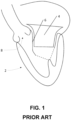
- a heart 2 showing LVOT obstruction is shown in FIG. 1 .
- a conventional TMVR apparatus 4 pushes anterior mitral valve leaflet 6 under aortic valve 8 obstructing outflow.
- Mitral valve replacement is complicated by the anatomy of the mitral valve, and particularly that of the mitral valve annulus in which the mitral valve leaflets are located.
- the mitral valve annulus is typically of unpredictable and nonuniform configuration, as compared to the relatively uniform aortic valve annulus.
- the unpredictable anatomy of the mitral valve annulus complicates safe, stable, and meticulous deployment of mitral valve prostheses.
- Transcatheter aortic valves for treating mitral regurgitation are known, and can be implanted when a suitable docking device (e.g. a surgically placed mitral annular ring) is present on the mitral valve.
- a suitable docking device e.g. a surgically placed mitral annular ring
- transcatheter aortic valves can suffer from similar complications as a TMVR apparatus, including LVOT obstruction when the replacement valve pushes the anterior mitral valve leaflet underneath the aortic valve.
- mitral valve replacement techniques involve the division or incision of the native valve prior to positioning and implanting the mitral valve prosthesis. This is a challenging technique associated with potentially fatal complications if the mitral valve prosthesis is not precisely positioned and/or the mitral valve prosthesis is not implanted at least closely or immediately following the division or incision of the native valve.
- US 2009/306582 A1 discloses a scoring catheter comprising an elongated catheter body and at least one scoring element positioned at the distal end of the catheter body, wherein said scoring element is expandable from a contracted state when positioned near said catheter body to an expanded state with a larger diameter so that diseased heart valves can be scored and reopened.
- Some aspects of the present disclosure provide an apparatus for use in mitral valve replacement comprising a controller, a cutting section movable between a collapsed position for delivering the apparatus to a mitral valve and an expanded position for incising a mitral valve leaflet, and a guidewire.
- the apparatus is sized and dimensioned to enter a subject through a first access site, traverse through at least part of a subject's circulatory system, and exit the subject through a second access site so that a distal end of the guidewire and the controller are external to the subject's circulatory system when the apparatus is situated intravascularly.
- a proximal end of the guidewire extends longitudinally from a distal end of the cutting section.
- a proximal end of the cutting section extends longitudinally from a distal end of the controller.
- the cutting section defines a lumen extending longitudinally through the cutting section and the guidewire extends through and is slideable within the cutting section.
- the cutting section comprises at least one blade configured to radially extend away from a longitudinal axis defined by the apparatus in the expanded position and radially collapse toward the longitudinal axis in the collapsed position.
- each blade is formed from a memory material.
- the memory material comprises a memory metal alloy from the group consisting of one or more of stainless steel, nickel, titanium, and nitinol.
- the blade retains a pre-deformed shape in the expanded position and is deformable into a deformed shape in the collapsed position.
- each blade comprises a cutting blade pivotally coupled at a proximal end to a distal end of a lever arm, each cutting blade pivotally coupled at a distal end to the proximal end of the guidewire and each lever arm pivotally coupled at a proximal end to the controller.
- the distance between the distal end of the cutting blade and the proximal end of the lever arm is greater in the collapsed position than in the expanded position.
- the cutting section comprises a rod and a runner longitudinally slidable about the rod.
- each blade comprises a distal end pivotally coupled to a distal section of the rod and a proximal end pivotally coupled to the runner.
- the distance between the proximal and distal ends of each blade is greater in the collapsed position than in the expanded position.
- the runner is rotatable about the rod to rotate each blade about the longitudinal axis.
- a radial cross-sectional area of the cutting section is reduced by rotating each blade about the longitudinal axis in a first direction.
- the radial cross-sectional area of the cutting section is increased by rotating each blade about the longitudinal axis in a second direction opposed to the first direction.
- the cutting section comprises a rotator housed within a case defining one or more slots configured to receive the at least one blade.
- each blade extends radially from the rotator and wraps concentrically about an inside surface of the case in the collapsed position.
- each blade is expandable and retractable within the slot.
- each blade extends radially from the rotator through the slot in the expanded position.
- the cutting section is configured to incise the mitral valve leaflet with a predetermined pattern.
- the predetermined pattern is selected from the group consisting of: a T-shaped incision, a linear incision, and an X-shaped incision.
- the at least one blade extends radially away from a longitudinal axis defined by the apparatus and in a configuration that corresponds to the predetermined pattern.
- controller is configured to move the cutting section from the collapsed position to the expanded position and vice versa.
- the method comprises inserting an apparatus percutaneously through a first access site of a subject, advancing the apparatus intravascularly through the subject's circulatory system, and advancing the apparatus through a second access site of the subject.
- the apparatus comprises a controller, a cutting section, and a guidewire and the apparatus is sized and dimensioned to traverse the subject's circulatory system from the first access site to the second access site such that a distal end of the guidewire and the controller are external to the subject's body when the apparatus is situated intravascularly.
- the method further comprises incising a mitral valve leaflet using the cutting section and delivering a prosthetic valve intravascularly to the incised mitral valve leaflet from the second access site using the guidewire.
- incising the mitral valve leaflet comprises expanding the cutting section from a collapsed position into an expanded position and advancing the cutting section in the expanded position through the mitral valve leaflet.
- the method further comprises positioning the prosthetic valve into the incised mitral valve leaflet following incision.
- the method further comprises positioning the prosthetic valve into the incised mitral valve leaflet immediately following incision.
- the method comprises positioning the prosthetic valve into the incised mitral valve leaflet within less than about 5 seconds following incision.
- the method comprises positioning the prosthetic valve into the incised mitral valve leaflet within less than about 3 seconds following incision.
- the method comprises positioning the prosthetic valve into the incised mitral valve leaflet within less than about 1 second following incision.
- the method comprises incising the mitral valve leaflet and implanting the prosthetic valve at a predetermined location determined using Transesophageal Echocardiography (TEE) and/or fluoroscopy techniques.
- TEE Transesophageal Echocardiography
- the predetermined location is selected to minimize or eliminate anterior displacement of the anterior leaflet.
- the predetermined location is along a central axis of the anterior leaflet at a position away from the anterior annulus so that an adequate amount of anterior leaflet tissue is available for hemostatic implantation of the prosthesis within a docking device.
- the predetermined location is selected to minimize or eliminate left ventricular outflow tract (LVOT) obstruction.
- LVOT left ventricular outflow tract
- inserting the apparatus through the first access site and advancing the apparatus through the subject's circulatory system comprises using a retrograde transcatheter approach.
- inserting the apparatus through the first access site and advancing the apparatus through the subject's circulatory system comprises using an antegrade transcatheter approach.
- advancing the apparatus through the second access site comprises inserting and advancing a snaring guidewire percutaneously through the second access site, snaring the distal end of the apparatus intravascularly, and withdrawing the distal end of the apparatus through the second access site.
- the apparatus comprises a controller, a cutting section movable between a collapsed position for delivering the apparatus to a mitral valve and an expanded position for incising a mitral valve leaflet, and a guidewire.
- the apparatus is sized and dimensioned to enter a subject through a first access site, traverse through at least part of a subject's circulatory system, and exit the subject through a second access site so that a distal end of the guidewire and the controller are external to the subject's circulatory system when the apparatus is situated intravascularly.
- a proximal end of the guidewire extends longitudinally from a distal end of the cutting section.
- a proximal end of the cutting section extends longitudinally from a distal end of the controller.
- the cutting section defines a lumen extending longitudinally through the cutting section and the guidewire extends through and is slideable within the cutting section.
- the cutting section comprises at least one blade configured to radially extend away from a longitudinal axis defined by the apparatus in the expanded position and radially collapse toward the longitudinal axis in the collapsed position.
- each blade is formed from a memory material.
- the memory material comprises a memory metal alloy from the group consisting of one or more of stainless steel, nickel, titanium, and nitinol.
- the blade retains a pre-deformed shape in the expanded position and is deformable into a deformed shape in the collapsed position.
- each blade comprises a cutting blade pivotally coupled at a proximal end to a distal end of a lever arm, each cutting blade pivotally coupled at a distal end to the proximal end of the guidewire and each lever arm pivotally coupled at a proximal end to the controller.
- the distance between the distal end of the cutting blade and the proximal end of the lever arm is greater in the collapsed position than in the expanded position.
- the cutting section comprises a rod and a runner longitudinally slidable about the rod.
- each blade comprises a distal end pivotally coupled to a distal section of the rod and a proximal end pivotally coupled to the runner.
- the distance between the proximal and distal ends of each blade is greater in the collapsed position than in the expanded position.
- the runner is rotatable about the rod to rotate each blade about the longitudinal axis.
- a radial cross-sectional area of the cutting section is reduced by rotating each blade about the longitudinal axis in a first direction.
- the radial cross-sectional area of the cutting section is increased by rotating each blade about the longitudinal axis in a second direction opposed to the first direction.
- the cutting section comprises a rotator housed within a case defining one or more slots configured to receive the at least one blade.
- each blade extends radially from the rotator and wraps concentrically about an inside surface of the case in the collapsed position.
- each blade is expandable and retractable within the slot.
- each blade extends radially from the rotator through the slot in the expanded position.
- the cutting section is configured to incise the mitral valve leaflet with a predetermined pattern.
- the predetermined pattern is selected from the group consisting of: a T-shaped incision, a linear incision, and an X-shaped incision.
- the at least one blade extends radially away from a longitudinal axis defined by the apparatus and in a configuration that corresponds to the predetermined pattern.
- controller is configured to move the cutting section from the collapsed position to the expanded position and vice versa.
- the system comprises a subaortic introducer and an apparatus comprising a controller, a cutting section movable between a collapsed position for delivering the apparatus to a mitral valve and an expanded position for incising a mitral valve leaflet, and a guidewire.
- the apparatus is sized and dimensioned to enter a subject through a first access site, traverse through at least part of a subject's circulatory system, and exit the subject through a second access site so that a distal end of the guidewire and the controller are external to the subject's circulatory system when the apparatus is situated intravascularly.
- the subaortic introducer comprises a destructible tip that maintains the guidewire in a linear position as the apparatus is advanced through a subject's circulatory system and permits the guidewire to deform in a J-shaped position as the apparatus destructs and is advanced through the tip.
- a proximal end of the guidewire extends longitudinally from a distal end of the cutting section.
- a proximal end of the cutting section extends longitudinally from a distal end of the controller.
- the cutting section defines a lumen extending longitudinally through the cutting section and the guidewire extends through and is slideable within the cutting section.
- the cutting section comprises at least one blade configured to radially extend away from a longitudinal axis defined the apparatus in the expanded position and radially collapse toward the longitudinal axis in the collapsed position.
- each blade is formed from a memory material.
- the memory material comprises a memory metal alloy from the group consisting of one or more of stainless steel, nickel, titanium, and nitinol.
- the blade retains a pre-deformed shape in the expanded position and is deformable into a deformed shape in the collapsed position.
- each blade comprises a cutting blade pivotally coupled at a proximal end to a distal end of a lever arm, each cutting blade pivotally coupled at a distal end to the proximal end of the guidewire and each lever arm pivotally coupled at a proximal end to the controller.
- the distance between the distal end of the cutting blade and the proximal end of the lever arm is greater in the collapsed position than in the expanded position.
- the cutting section comprises a rod and a runner longitudinally slidable about the rod.
- each blade comprises a distal end pivotally coupled to a distal section of the rod and a proximal end pivotally coupled to the runner.
- the distance between the proximal and distal ends of each blade is greater in the collapsed position than in the expanded position.
- the runner is rotatable about the rod to rotate each blade about the longitudinal axis.
- a radial cross-sectional area of the cutting section is reduced by rotating each blade about the longitudinal axis in a first direction.
- the radial cross-sectional area of the cutting section is increased by rotating each blade about the longitudinal axis in a second direction opposed to the first direction.
- the cutting section comprises a rotator housed within a case defining one or more slots configured to receive the at least one blade.
- each blade extends radially from the rotator and wraps concentrically about an inside surface of the case in the collapsed position.
- each blade is expandable and retractable within the slot.
- each blade extends radially from the rotator through the slot in the expanded position.
- the cutting section is configured to incise the mitral valve leaflet with a predetermined pattern.
- the predetermined pattern is selected from the group consisting of: a T-shaped incision, a linear incision, and an X-shaped incision.
- the at least one blade extends radially away from a longitudinal axis defined by the apparatus and in a configuration that corresponds to the predetermined pattern.
- controller is configured to move the cutting section from the collapsed position to the expanded position and vice versa.
- anterior refers to a position that is more near the front surface of the subject's body or part thereof than the rear surface of the subject's body or part thereof.
- the term "posterior" refers to a position that is more near the rear surface of the subject's body or part thereof than the front surface of the subject's body or part thereof.
- proximal refers to a position that is more near a controller of the apparatus or part thereof.
- distal refers to a position that is situated further away from a controller of the apparatus or part thereof.
- percutaneous refers to a method of accessing a subject's circulatory system and/or heart through the skin, such as by needle access.
- the term "antegrade” refers to a percutaneous approach to a mitral valve via a subject's femoral vein, right atrium, atrial septal puncture, and left atrium.
- the term "retrograde” refers to a percutaneous approach to a mitral valve via a subject's femoral artery, wherein the left ventricle is accessed via the aortic valve.
- intravascular means situated or occurring within a subject's blood vessel or circulatory system.
- the term "external" (as used herein in relation to a subject's body and parts thereof) means situated outside of a subject's circulatory system or body.
- transcatheter refers to a method performed intravascularly through the lumen of a catheter.
- the term “collapsed position” refers to a radially compressed state.
- radial refers to a radially compressed state.
- expansion position refers to a radially enlarged, extended, or otherwise broadened state.
- circulatory system refers to a system that circulates blood and/or lymph through a subject's body, consisting of one or more of a heart, blood vessels, blood, lymph, lymphatic vessels, and lymphatic glands.
- transcatheter heart valve prosthesis refers to a prosthesis used to repair or replace a heart valve (e.g. mitral valve, aortic valve, etc.) percutaneously using a transcatheter heart valve delivery system, including (but not limited to) a transcatheter mitral valve prosthesis.
- subject refers to a human and/or an animal (i.e. a bird and/or a mammal) and includes any subject that will benefit or that is likely to benefit from the present invention (for example, a subject with a condition affecting the normal functioning of a heart valve, including (but not limited to) the mitral valve, for example, mitral valve regurgitation, mitral valve prolapse, and mitral valve stenosis.
- mitral valve for example, mitral valve regurgitation, mitral valve prolapse, and mitral valve stenosis.
- Nitinol refers to a nickel-titanium alloy with shape memory and/or superelastic characteristics. Nitinol is capable of deforming into a deformed shape and recovering its original, undeformed shape without applying heat.
- the methods and apparatus disclosed may be used for the percutaneous repair of any of the cardiac valves, the following description will focus on the replacement of mitral valves.
- the methods and apparatus disclosed will preferably be percutaneous and intravascular, such methods and apparatus may be used for performing open heart surgery where the heart is accessed through the myocardial tissue and/or in minimally invasive procedures where access to the heart is achieved thorascopically.
- the methods and apparatus disclosed will preferably be used with conventional transcatheter heart valve prostheses, such methods and apparatus may be used with prostheses implanted through the myocardial tissue of the heart and/or prostheses implanted using minimally invasive procedures where access to the heart is achieved thorascopically.
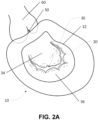
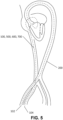
- the human heart 10 shown in FIGS. 2A and 2B , is a muscle pump which relies on heart valves to achieve forward blood flow.
- oxygenated blood returning from the lungs is collected in a left atrium 20, and then passes through a mitral (inlet) valve 30 to enter a left ventricle 40 (i.e. the pumping chamber).
- a mitral (inlet) valve 30 With contraction of left ventricle 40, the elevation of left ventricular pressure causes mitral valve 30 to close, preventing reversal of blood flow back into atrium 20.
- aortic (outlet) valve 50 opens, and blood is pumped forward into aorta 60.
- mitral valve 30 reopens to permit flow of blood from left atrium 20 to left ventricle 40, and the process repeats.
- Mitral valve 30 separates left atrium 20 from left ventricle 40, and is comprised of a mitral annulus 32, leaflets (anterior 34 and posterior 36), chordae tendinae 38, and papillary muscles 39.
- mitral valve leaflets 34, 36 During ventricular contraction (systole), the ventricular pressure rises, which forces displacement of mitral valve leaflets 34, 36 towards atrium 20 (i.e. commonly known as atrial or leaflet displacement).
- the length and integrity of chordae tendinae 38 determines the degree of leaflet displacement.
- equal displacement of anterior mitral valve leaflet 34 and posterior mitral valve leaflet 36 results in contact (coaptation) between the leaflets, and consequent competence of mitral valve 30.
- mitral valve leaflet prolapse In this circumstance, the competency of mitral valve 30 may be compromised and leakage may occur. Leakage through the mitral valve is referred to as mitral regurgitation, and when it is due to mitral valve leaflet prolapse it is referred to as degenerative mitral regurgitation. In other circumstances, the ventricular muscle itself can be diseased and its function impaired causing limited ventricular contraction and progressive ventricular dilation.
- mitral valve leaflets 34, 36 are attached by chordae tendinae 38 to the ventricular muscle, ventricular dilation can limit leaflet movement toward atrium 20 during contraction, resulting in poor leaflet coaptation and causing mitral regurgitation. This is referred to as functional mitral regurgitations.
- the methods and apparatus of example embodiments use existing transcatheter heart valve prostheses to percutaneously replace a mitral valve.
- the methods and apparatus of example embodiments are used to percutaneously incise an anterior mitral valve leaflet and to permit precise implantation of a transcatheter heart valve prosthesis in that incision. In this way, incision and implantation are both controlled, deliberate, and precise and LVOT obstruction may be avoided or minimized.
- the size and design of the incision may be controlled to optimize implantation.
- Some embodiments use percutaneous incision of the anterior mitral valve leaflet to allow a transcatheter heart valve prosthesis to be implanted after the mitral valve leaflet is incised to reduce or eliminate the risk of hemodynamic instability.
- FIGS. 4A-4F An apparatus 10D for use in replacing a heart valve, such as a mitral valve, is shown in FIGS. 4A-4F .
- apparatus 500, apparatus 600, and apparatus 700 are shown in FIGS. 8A-8J , 9A-9H , and 10A-10D .
- Many features and components of apparatus 500, 600, 700 are similar to features and components of apparatus 100, with the same reference numerals being used to indicate features and components that are similar between the embodiments.
- apparatus 100, 500, 600, 700 is used to percutaneously incise an anterior mitral valve leaflet and to permit precise implantation of a transcatheter heart valve prosthesis in the incision.
- Apparatus 100, 500, 600, 700 is sized and dimensioned to traverse a subject's circulatory system percutaneously from a first access site to a second access site.
- the first access site enters the subject's femoral artery or femoral vein.
- the second access site enters the subject's femoral artery or femoral vein.
- the example embodiment of apparatus 10D shown in FIGS. 5 and 11A-11J traverses a subject's circulatory system 200 from a first access site 106 (FIGS.
- proximal end 102 is external the femoral artery and distal end 104 is external the femoral vein when apparatus 100 is situated intravascularly and traverses the subject's circulatory system.
- proximal end 102 may be external the femoral artery and the distal end 104 may be external the femoral vein when apparatus 100 is situated intravascularly and traverses the subject's circulatory system.
- the apparatus includes a controller, a cutting section, and a guidewire.
- the apparatus is configured to be operated external to a subject's body.
- the controller may be operated external to the subject's body to advance the apparatus intravascularly through the subject's circulatory system from a first access site (e.g. access site 106 (FIGS. 11A-11J)) to a second access site (e.g. access site 108 (FIGS. 11A-11J)).
- the controller is configured to operate the cutting section and/or the guidewire intravascularly from outside the subject's body, as described elsewhere herein.
- the controller (e.g. controller 110) is operable to move the apparatus between a collapsed position and an expanded position.
- the apparatus In the collapsed position, the apparatus is in a radially compressed state to intravascularly traverse a subject's circulatory system.
- the apparatus In the expanded position, the apparatus is in a radially enlarged, extended, or otherwise broadened state whereby the radial cross-sectional area of the apparatus is greater in the expanded position than in the collapsed position.
- the apparatus In the expanded position, the apparatus is operable for incising a mitral valve leaflet.
- the cutting section e.g. cutting section 120, 520, 620, 720
- FIGS. 4C-4F , 8E-8H , 8J , 9E-9H , and 10C-10D In the collapsed position, the cutting section is in a radially compressed state to reduce the cross-sectional area of the cutting section. In the expanded position, the cutting section is in a radially enlarged, extended, or otherwise broadened state whereby the radial cross-sectional area of the cutting section is greater in the expanded position than in the collapsed position.
- a guidewire (e.g. guidewire 130, 530, 630, 730) longitudinally extends from the cutting section for guiding and positioning the cutting section to incise a mitral valve leaflet and for positioning a transcatheter heart valve prosthesis (e.g. a mitral valve prosthesis) into the incised leaflet as described elsewhere herein.
- the transcatheter heart valve prosthesis may be precisely positioned within the incision following incision to reduce or eliminate the risk of hemodynamic instability.
- the transcatheter heart valve prosthesis is positioned within the incision within less than about 5 seconds following incision. In some embodiments the transcatheter heart valve prosthesis is positioned within the incision within less than about 3 seconds following incision.
- the transcatheter heart valve prosthesis is positioned within the incision within less than about 1 second following incision. In some embodiments the transcatheter heart valve prosthesis is closely or immediately positioned within the incision following incision. Precise positioning of the transcatheter heart valve prosthesis may avoid or minimize LVOT obstruction. Immediate positioning of the transcatheter heart valve prosthesis following incision may minimize the risk of hemodynamic instability.
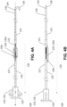
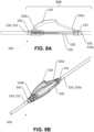
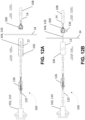
- apparatus 100 includes a cutting section 120, a guidewire 130 extending away from a distal end of cutting section 120, and a controller 110 extending away from a proximal end of cutting section 120 opposed to the distal end.
- controller 110 includes a handle 116 and a knob 118.
- Handle 116 has a lumen (not shown) extending longitudinally therethrough.
- a rod 119 coupled to knob 118 extends through the lumen and slides within the lumen to move rod 119 and knob 118 concentrically and/or longitudinally relative to handle 116.
- apparatus 100 may be operated.
- cutting section 120 is rotatable relative to controller 110.
- controller 110 and cutting section 120 are rotatably fixed such that rotation of controller 110 rotates cutting section 120.
- Guidewire 130 comprises a proximal end 132 ( FIG. 4F ) coupled to cutting section 120 and a distal end 134 opposed to the proximal end.
- guidewire 130 is rotatable relative to controller 110 and/or cutting section 120.
- cutting section 120 and guidewire 130 are rotatably fixed such that rotation of cutting section 120 rotates guidewire 130 and vice versa.
- distal end 134 of guidewire 130 includes a hook 136 for engaging a snaring guidewire as described elsewhere herein. Other means for engaging a snaring guidewire are considered to be within the knowledge of persons skilled in the art of interventional cardiology.
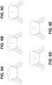
- Cutting section 120 includes one or more radially expandable blades 126 for incising a mitral valve leaflet. Each blade 126 may be expanded or contracted using controller 110. In the embodiment illustrated in FIGS. 4A-4F , cutting section 120 includes three radially expandable blades 126 configured to incise the mitral valve leaflet with a "T-shaped" incision. The number and configuration of the blades of apparatus 100 may be selected to achieve other desired incision patterns. For example, the number and configuration of blades 126 may be selected to incise a mitral valve leaflet with a "T-shaped" incision, a linear incision, or an "X-shaped" incision ( FIGS. 6A-6E ). Other incision patterns are considered to be within the knowledge of persons skilled in the art of heart surgery. In some embodiments, each blade 126 is expandable and retractable within a corresponding blade window (not shown) defined by the cutting section.
- each blade 126 comprises a cutting blade 126a pivotally coupled to a lever arm 126b by a hinge 126c.
- Hinge 126c may comprise a pin, a screw, or another mechanical fastener conventionally known.
- cutting section 120 includes a rod 129 coupled to rod 119 at a proximal end 129a and coupled to lever arm 126b at a distal end 129b ( FIG. 4F ).
- rods 119, 129 are coupled together.
- rods 119, 129 are formed together as a unitary rod (not shown).
- lever arm 126b is pivotally coupled to distal end 129b by a hinge (not shown), such as a pin, a screw, or another mechanical fastener conventionally known.
- Cutting blade 126a is coupled to a proximal end 132 of guidewire 130.
- cutting blade 126a is pivotally coupled to guidewire 130 by a hinge (not shown), such as a pin, a screw, or another mechanical fastener conventionally known.
- FIGS. 4A-4B In a collapsed position ( FIGS. 4A-4B ), cutting blade 126a and lever arm 126b are folded together about hinge 126c in a radially compressed state to reduce the cross-sectional area of cutting section 120 so that apparatus 100 may be inserted percutaneously and traversed intravascularly.
- knob 118 coupled to rod 119 is pulled away from handle 116 along an axis A defined by apparatus 100 ( FIG. 4A ). In this way, rod 129 coupled to rod 119 longitudinally slides within the lumen (not shown) defined by handle 116, thereby pulling distal end 129b of rod 129 away from proximal end 132 of guidewire 130.
- cutting blade 126a and lever arm 126b unfold about hinge 126c and radially extend away from axis A. In this way, cutting blade 126a is oriented to incise a mitral valve leaflet as described elsewhere herein.
- knob 118 is pushed toward handle 116 along axis A, drawing distal end 129b of rod 129 toward proximal end 132 of guidewire 130 and folding cutting blade 126a and lever arm 126b about hinge 126c.
- Cutting blade 126a and lever arm 126b radially compress towards axis A.
- apparatus 100 may be inserted into a catheter (e.g. catheter 12).
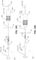
- apparatus 100 includes a blade tube 121 (although this is not necessary).
- Blade tube 121 defines a lumen (not shown) extending longitudinally therethrough and one or more slots 121c, each slot 1221c configured to permit blade 126 to pass therethrough.
- Distal end 129b of rod 129 and proximal end 132 of guidewire 130 extend through the lumen.
- blade tube 121 spans a gap between distal end 129b of rod 129 and proximal end 132 of guidewire 130 when apparatus 100 is in an expanded position.
- blade tube 121 couples cutting section 120 and guidewire 130 together along axis A.
- Blade tube 121 prevents material from becoming lodged between cutting section 120 and guidewire 130 when apparatus 100 is in an expanded position.
- Blade tube 121 may enhance the precision of apparatus 100 in incising a mitral valve leaflet and implanting a transcatheter heart valve prosthesis as described elsewhere herein.
- apparatus 100 includes a connecting tube 123 (although this is not necessary).
- Connecting tube 123 defines a lumen (not shown) extending longitudinally therethrough.
- a distal end 121b of blade tube 121 and proximal end 132 of guidewire 130 extend through the lumen.
- connecting tube 123 rigidly couples cutting section 120 and guidewire 130 together along axis A.
- Connecting tube 123 may enhance the precision of apparatus 100 in incising a mitral valve leaflet and implanting a transcatheter heart valve prosthesis as described elsewhere herein.
- apparatus 100 includes a rod tube 125 (although this is not necessary).
- Rod tube 125 defines a lumen (not shown) extending longitudinally therethrough.
- a proximal end 121a of blade tube 121 and rod 129 extend through the lumen and longitudinally slides within the lumen.
- Rod tube 125 may enhance the rigidity of apparatus 100.
- rod tube 125 may rigidly couple controller 110 and cutting section 120 together along axis A.
- Rod 119 and/or rod 129 are slidable within the lumen of rod tube 125 along axis A.
- apparatus 100 includes a tube 127 (although this is not necessary).
- Tube 127 defines a lumen (not shown) extending longitudinally therethrough.
- a proximal end 121a of blade tube 121 and rod tube 125 (and/or rod 129) extend through the lumen and longitudinally slides within the lumen.
- Tube 127 may enhance the rigidity of apparatus 100.
- apparatus 100 and/or the parts thereof comprise a sterilized or sterilisable material.
- apparatus 100 and/or the parts thereof comprise one or more of medical grade plastic, thermal plastic, stainless steel, metal, a metal alloy (e.g. nitinol or another nickel/titanium alloy), and titanium.
- apparatus 100 and/or the parts thereof may be made of any sterilized or sterilisable material conventionally used to manufacture tools used in heart surgery.
- each blade 126 is formed from a sterilized or sterilisable memory material, such as a memory metal alloy including (but not limited to) stainless steel and/or nickel and/or titanium and/or nitinol.
- a sterilized or sterilisable memory material such as a memory metal alloy including (but not limited to) stainless steel and/or nickel and/or titanium and/or nitinol.
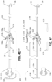
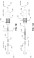
- Blade 126d shown in FIG. 7 are constructed in one-piece from a sterilized or sterilisable memory material, such as a memory metal alloy including (but not limited to) stainless steel and/or nickel and/or titanium and/or nitinol.
- Blade 126d retains a pre-deformed shape in the expanded position shown in FIG. 7 .
- Each blade 126d is deformable into the collapsed position (not shown).
- a proximal end 126e of blade 126d is coupled to distal end 129b ( FIG. 4F ) of rod 129.
- proximal end 126e is pivotally coupled to rod 129 by a hinge (not shown), such as a pin, a screw, or another mechanical fastener conventionally known.
- a distal end 126f of blade 126d is coupled to a proximal end 132 of guidewire 130.
- distal end 126f is pivotally coupled to guidewire 130 by a hinge (not shown), such as a pin, a screw, or another mechanical fastener conventionally known.
- blade 126d In a collapsed position (not shown), blade 126d is deformed in a radially compressed state to reduce the cross-sectional area of cutting section 120 so that apparatus 100 may be inserted percutaneously and traversed intravascularly.
- knob 118 coupled to rod 119 is advanced toward handle 116 along an axis B defined by apparatus 100 ( FIG. 7 ).
- rod 129 coupled to rod 119 longitudinally slides within the lumen (not shown) defined by handle 116, thereby pushing distal end 129b of rod 129 toward proximal end 132 of guidewire 130.
- apparatus 100 may be inserted into a catheter (e.g. catheter 12).
- apparatus 500 includes a cutting section 520, a guidewire 530 extending away from a distal end of cutting section 520, and a controller (not shown) extending away from a proximal end of cutting section 520 opposed to the distal end.
- the controller includes a handle (not shown) and a knob (not shown).
- the handle has a lumen (not shown) extending longitudinally therethrough.
- a rod (not shown) coupled to the knob extends through the lumen and longitudinally slides within the lumen to move the rod and the knob concentrically and/or longitudinally relative to the handle. By longitudinally sliding and/or rotating the knob relative to the handle, apparatus 500 may be operated.
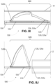
- Cutting section 520 includes one or more radially expandable blades 526 for incising a mitral valve leaflet. Each blade 526 may be expanded or contracted using the controller. In the embodiment illustrated in FIGS. 8A-8J , cutting section 520 includes three radially expandable blades 526 configured to incise the mitral valve leaflet with a "T-shaped" incision. The number and configuration of the blades of apparatus 500 may be selected to achieve other desired incision patterns as described elsewhere herein. Each blade 526 is constructed in one-piece from a sterilized or sterilisable memory material, such as a memory metal alloy including (but not limited to) stainless steel and/or nickel and/or titanium and/or nitinol.
- a sterilized or sterilisable memory material such as a memory metal alloy including (but not limited to) stainless steel and/or nickel and/or titanium and/or nitinol.
- Each bade 526 retains a pre-deformed shape in the expanded position shown in FIGS. 8E-8H and 8J .
- Each blade 526 is deformable into the collapsed position shown in FIGS. 8A-8D and 8I .
- each blade 526 may comprise a cutting blade pivotally coupled to a lever arm by a hinge. Such blades are structurally and functionally similar to blades 126 of apparatus 100.
- cutting section 520 includes a runner 570.
- a proximal end 526a of each blade 526 is coupled to runner 570.
- a distal end 526b of each blade 526 is coupled to guidewire 530.
- Runner 570 defines a lumen (not shown) extending longitudinally therethrough.
- Runner 570 is slideably mounted about a rod 528.
- Rod 528 extends from the controller through the lumen of runner 570 to permit the runner to slide longitudinally across rod 528.
- Runner 570 is coupled to a distal end 529a of a tube 529 for operating cutting section 520.
- Tube 529 is coupled to handle 116 of the controller for sliding runner 570 along rod 528 by pulling or pushing knob 118.
- Tube 529 defines a lumen (not shown) extending longitudinally therethrough.
- Rod 528 extends through the lumen of tube 529.
- apparatus 500 includes a joint 540 fixedly coupled to a proximal end 532 of guidewire 530 and a distal end 526b of each cutting blade 526 is coupled to joint 540.
- Runner 570 longitudinally slides across rod 528 relative to joint 540.
- Each blade 526 is movable from a collapsed position ( FIGS. 8A-8D and 8I ) into a radially expanded position ( FIGS. 8E-8H and 8J ) by pushing tube 529 toward joint 540 along an axis C defined by apparatus 500 ( FIG. 8C ). In this way, runner 570 slides along rod 528 towards joint 540.
- apparatus 500 may be inserted into a catheter (e.g. catheter 12).
- apparatus 500 and/or the parts thereof comprise a sterilized or sterilisable material.
- apparatus 500 and/or the parts thereof comprise one or more of medical grade plastic, thermal plastic, stainless steel, metal, a metal alloy (e.g. nitinol or another nickel/titanium alloy), and titanium.
- apparatus 500 and/or the parts thereof may be made of any sterilized or sterilisable material conventionally used to manufacture tools used in heart surgery.
- the cutting section includes one or more blades that are rotatably deformable.
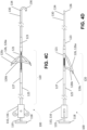
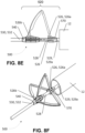
- apparatus 600 shown in FIGS. 9A-9H comprises three rotatably deformable blades 626.
- apparatus 600 includes a cutting section 620, a guidewire 630 extending away from a distal end of cutting section 620, and a controller (not shown) extending away from a proximal end of cutting section 620 opposed to the distal end.
- controller includes a handle (not shown) and a knob (not shown).
- the handle has a lumen (not shown) extending longitudinally therethrough.
- a rod (not shown) coupled to the knob extends through the lumen and longitudinally slides within the lumen to move the rod and the knob concentrically and/or longitudinally relative to the handle. By longitudinally sliding and/or rotating the knob relative to the handle, apparatus 500 may be operated.
- Cutting section 620 includes one or more radially expandable blades 626 for incising a mitral valve leaflet. Each blade 626 may be expanded or contracted using the controller. In the embodiment illustrated in FIGS. 9A-9H , cutting section 620 includes three radially expandable blades 626 configured to incise the mitral valve leaflet with a "T-shaped" incision. The number and configuration of the blades of apparatus 600 may be selected to achieve other desired incision patterns as described elsewhere herein. Each blade 626 is constructed in one-piece from a sterilized or sterilisable memory material, such as a memory metal alloy including (but not limited to) stainless steel and/or nickel and/or titanium and/or nitinol. Each bade 626 retains a pre-deformed shape in the expanded position shown in FIGS. 9E-9H . Each blade 626 is deformable into the collapsed position shown in FIGS. 9A-9D .
- a sterilized or sterilisable memory material such as a memory metal
- cutting section 620 includes a runner 670.
- a proximal end 626a of each blade 626 is coupled to runner 670.
- a distal end 626b of each blade 626 is coupled to guidewire 630.
- Runner 670 defines a lumen (not shown) extending longitudinally therethrough.
- Runner 670 is rotatably mounted about a rod 628.
- runner 670 is rotatably and slideably mounted to rod 628.
- Rod 628 extends from the controller through the lumen of runner 670 to permit the runner to rotate concentrically about rod 628 and/or slide longitudinally across rod 628.
- Runner 670 is coupled to a distal end 629a of a tube 629 for operating cutting section 620.
- Tube 629 is coupled to handle 116 of the controller for sliding runner 670 along rod 628 by pulling or pushing knob 118.
- Tube 629 defines a lumen (not shown) extending longitudinally therethrough.
- Rod 628 extends through
- apparatus 600 includes a joint 640 fixedly coupled to a proximal end 632 of guidewire 630 and a distal end 626b of each cutting blade 626 is coupled to joint 640.
- runner 670 longitudinally slides across rod 628 relative to joint 640.
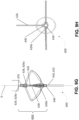
- Each blade 626 is movable from a collapsed position ( FIGS. 9A-9D ) into a radially expanded position ( FIGS. 9E-9H ) by rotating runner 670 relative to fixed joint 640 concentrically in a first direction about an axis D defined by apparatus 600 ( FIG. 9C ).
- each blade 626 is rotatably deformed about rod 621, reducing the radial cross-sectional area of the cutting section.
- apparatus 600 may be inserted into a catheter (e.g. catheter 12).
- each blade 626 By rotating tube 629 relative to fixed joint 640 concentrically in a second direction opposite the first direction about axis D, each blade 626 is returned to a pre-deformed state in the expanded position whereby the radial cross-sectional area of the cutting section is greater in the expanded position than in the collapsed position. In this position, blade 626 is oriented to incise a mitral valve leaflet as described elsewhere herein.
- the distance between ends 626a, 626b of blade 626 increases and each blade 626 radially contracts towards axis D.
- tube 629 is pushed towards fixed joint 640 along axis D (with or without rotation in the second direction), drawing runner 670 towards joint 640.
- runner 670 is pushed towards joint 640 along axis D, the distance between ends 626a, 626b of blade 626 decreases and each blade 626 radially expands away from axis D.
- apparatus 600 and/or the parts thereof comprise a sterilized or sterilisable material.
- apparatus 600 and/or the parts thereof comprise one or more of medical grade plastic, thermal plastic, stainless steel, metal, a metal alloy (e.g. nitinol or another nickel/titanium alloy), and titanium.
- apparatus 600 and/or the parts thereof may be made of any sterilized or sterilisable material conventionally used to manufacture tools used in heart surgery.
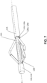
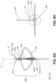
- apparatus 700 includes a cutting section 720, a guidewire 730 extending away from a distal end of cutting section 720, and a controller (not shown) extending away from a proximal end of cutting section 720 opposed to the distal end.
- the controller includes a handle (not shown) and a knob (not shown).
- the handle has a lumen (not shown) extending longitudinally therethrough.
- a rod (not shown) coupled to the knob extends through the lumen and longitudinally slides within the lumen to move the rod and the knob concentrically and/or longitudinally relative to the handle. By longitudinally sliding and/or rotating the knob relative to the handle, apparatus 700 may be operated.
- Cutting section 720 includes one or more radially expandable blades 726 for incising a mitral valve leaflet. Each blade 726 may be expanded or contracted using the controller.
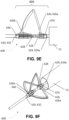
- cutting section 720 includes a rotator 760 housed within a case 780. Case 780 comprises at least one slot 782, each slot 782 configured to receive a corresponding blade 726 therethrough. Each blade 726 is expandable and retractable within a corresponding slot 782 defined by case 780.
- rotator 760 is coupled to rod 129 and rotator 760 is actuated by rotating rod 129.
- rotator 760 extends longitudinally through the controller for actuating cutting section 720 by rotating rotator 760.
- cutting section 720 includes three radially expandable blades 726a, 726d, 726g configured to incise the mitral valve leaflet with a "T-shaped" incision ( FIG. 10C ).
- the number and configuration of the blades of apparatus 700 may be selected to achieve other desired incision patterns as described elsewhere herein.
- Each blade 726 is constructed in one-piece from a sterilized or sterilisable memory material, such as a memory metal alloy including (but not limited to) stainless steel and/or nickel and/or titanium and/or nitinol.
- Each bade 726 retains a pre-deformed shape in the expanded position shown in FIGS. 10C-10D .
- Each blade 726 is deformable into the collapsed position shown in FIGS. 10A-10B by operating rotator 760.
- one or more blades 726 are solid in construction.
- one or more blades 726 comprise one or more openings (not shown) to permit deformation within case 780, while maintaining a desirable shape and mount of force to incise a heart valve leaflet.
- a first end 726b of blade 726a is attached to an arm 762 coupled to and extending radially away from rotator 760.
- a first end 726e of blade 726d is attached to arm 762 so that ends 726b, 726e are coupled to opposed sides of arm 762.
- a first end 726h of blade 726g is coupled to rotator 760.
- end 726h is coupled to rotator 760 at a position that is substantially opposed to arm 762 about the diameter of rotator 760.
- Blades 726a, 726d extend from arm 762 and wrap concentrically about an inside surface 781 of case 780 in a first direction (i.e. in the counter-clockwise direction in FIG.
- Blade 726g extends from rotator 760 and wraps concentrically about inside surface 781 in the first direction. With blades 726a, 726d, 726g wrapped concentrically about inside surface 781, cutting section 720 of apparatus 700 is in a collapsed position ( FIGS. 10A-10B ).
- Cutting section 720 is movable from the collapsed position ( FIGS. 10A-10B ) into a radially expanded position ( FIGS. 10C-10D ) by rotating rotator 760 in the first direction. Ends 726c, 726f, 726i of blades 726a, 726d, 726g move concentrically about inside surface 781 of case 780 in the first direction and advance through slots 782.
- blade 726d comprises a wedge 729 coupled adjacent to end 726f. Wedge 729 contacts inside surface 781 as blade 726d moves concentrically inside case 780.
- wedge 729 prevents blade 726d from advancing through slot 782a. Wedge 729, however, does not prevent blade 726d from advancing through slot 782d. In this way, blade 726a advances through slot 782a, blade 726d advances through slot 782d, and blade 726g advances through slot 782g ( FIG. 10C ).
- rotator 760 is rotated in a second direction (i.e. in the clockwise direction in FIG. 10A ), wrapping each blade 726 concentrically about inside surface 781 of case 780 ( FIG. 10A ).
- apparatus 700 and/or the parts thereof comprise a sterilized or sterilisable material.
- apparatus 700 and/or the parts thereof comprise one or more of medical grade plastic, thermal plastic, stainless steel, metal, a metal alloy (e.g. nitinol or another nickel/titanium alloy), and titanium.
- apparatus 700 and/or the parts thereof may be made of any sterilized or sterilisable material conventionally used to manufacture tools used in heart surgery.
- FIGS. 11A-11G and 12A-12J A method for replacing a mitral valve of a heart according to an example embodiment is shown in FIGS. 11A-11G and 12A-12J .
- the features and parts of the heart are similar to features and parts of heart 10, with the same reference numerals being used to indicate features and parts that are similar.
- the method shown in FIGS. 12A-12J demonstrates the use of apparatus 100. Apparatus 500, 600, 700 are deployed similarly as described elsewhere herein.
- apparatus 100, 500, 600, 700 is inserted into first access site 106 of a subject and advanced using a transcatheter approach conventionally known.
- Apparatus 100, 500, 600, 700 may be inserted using a subaortic introducer.
- guidewire 130, 530, 630, 730 may define a hook 136 at a distal end 134 thereof.
- Distal end 134 may be "J-shaped" to avoid damaging heart tissue, while retaining a sharp tip to puncture a heart valve leaflet.
- the subaortic introducer must maintain guidewire 130, 530, 630, 730 in a linear position as apparatus 100, 500, 600, 700 is advanced through the subject's circulatory system, but must permit distal end 134 of guidewire 130, 530, 630, 730 to deform into a J-shaped configuration defining hook 136 as guidewire 130, 530, 630, 730 exits the subaortic introducer.
- the subaortic introducer may comprise a tip constructed from a material that may be stretched and/or torn by applying a force to distal end 134 of guidewire 130, 530, 630, 730.
- the tip is constructed from a rigid material defining one or more points of weakness to advance guidewire 130, 530, 630, 730 therefrom.
- apparatus 100, 500, 600, 700 may be inserted using a conventional subaortic introducer (e.g. subaortic introducer 12) ( FIG. 11A and 12A ) or other device considered to be within the knowledge of persons skilled in the art of interventional cardiology.
- apparatus 100, 500, 600, 700 is advanced through introducer 14 using an antegrade transcatheter approach. In some other embodiments, apparatus 100, 500, 600, 700 is advanced through introducer 12 using a retrograde transcatheter approach.
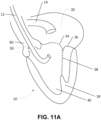
- guidewire 130, 530, 630, 730 is advanced through introducer 12 intravascularly through the artery and through an aortic valve to retroflex towards a ventricular surface of anterior leaflet 34 of mitral valve 30 ( FIGS. 11B and 12A ).
- Guidewire 130, 530, 630, 730 is punctured and advanced through the anterior leaflet ( FIGS.
- the location of the guidewire puncture through anterior leaflet 34 defines the location through which cutting section 120, 520, 620, 720 will be advanced, and so guidewire 130, 530, 630, 730 is used to define the location where a transcatheter heart valve prosthesis will ultimately be implanted.
- the location of the guidewire puncture is selected so that anterior displacement of the anterior leaflet is minimized when a transcatheter heart valve prosthesis is implanted. In this way, LVOT obstruction may be avoided or minimized.
- the location of the guidewire puncture is along a central axis of the anterior leaflet at a position away from the anterior annulus so that an adequate amount of anterior leaflet tissue is available for hemostatic implantation of a transcatheter heart valve prosthesis within a docking device (not shown) and LVOT obstruction may be avoided or minimized.
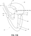
- guidewire 130, 530, 630, 730 is snared by a snaring guidewire 300 as is conventionally known and traversed through the femoral vein to exit the subject's circulatory system at second access site 108 ( FIGS. 11C and 12B ).
- Snaring guidewire 300 is introduced into the femoral vein via second access site 108 using an antegrade transcatheter approach conventionally known.
- snaring guidewire 300 may be inserted using a conventional transseptal introducer (e.g. transseptal introducer 14) or other device considered to be within the knowledge of persons skilled in the art of interventional cardiology.
- Snaring guidewire 300 is advanced through the femoral vein, through an atrial septum, to a left atrium of the subject's heart. Snaring guidewire 300 is positioned to face an atrial surface of anterior mitral valve leaflet 34. Snaring guidewire 300 snares distal end 134 of guidewire 130, 530, 630, 730 and withdraws guidewire 130, 530, 630, 730 through the subject's atrial septum. Guidewire 130, 530, 630, 730 and snaring guidewire 300 exit the subject's circulatory system through second access site 108 via the femoral vein.
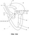
- cutting section 120, 520, 620, 720 is advanced in a collapsed position through the subject's femoral artery and may be positioned adjacent the ventricular surface of anterior mitral valve leaflet 34 ( FIGS. 11D and 12D ).
- guidewire 130, 530, 630, 730 is coupled to corresponding cutting section 120, 520, 620, 720 and, accordingly, as guidewire 130, 530, 630, 730 is withdrawn through second access site 108, corresponding cutting section 120, 520, 620, 720 is simultaneously advanced in the collapsed position through the subject's femoral artery and positioned adjacent the ventricular surface of anterior mitral valve leaflet 34.
- a compressed transcatheter heart valve prosthesis 400 (conventionally known) and its delivery system 16 may be passed over guidewire 130, 530, 630, 730 and introduced into the femoral vein via second access site 108 to be positioned in the subject's heart ( FIGS. 12C and 12D ).
- prosthesis 400 is ready to be advanced into a precise implant location closely or immediately following incision of the anterior leaflet by cutting section 120, 520, 620, 720 as described elsewhere herein.
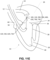
- FIGS. 12C-12D With guidewire 130, 530, 630, 730 extending through anterior mitral valve leaflet 34, cutting section 120, 520, 620, 720 is advanced in a collapsed position to the ventricular surface of the anterior mitral valve leaflet. With prosthesis 400 positioned over guidewire 130, 530, 630, 730 inside the left atrium, prosthesis 400 is deliverable along guidewire 130, 530, 630, 730 to the incision site closely following incision. To incise the anterior leaflet, cutting section 120, 520, 620, 720 is deployed into an expanded position as described elsewhere herein and is advanced through the anterior leaflet incising the leaflet ( FIGS. 11D-11E , and 12E-12H ).
- FIG. 12I After incising anterior mitral valve leaflet 34, cutting section 120, 520, 620, 720 is collapsed into the collapsed position and withdrawn through the incision into the left ventricle ( FIG. 12I ). Prosthesis 400 is then advanced over guidewire 130, 530, 630, 730 and positioned within the incision ( FIG. 11F and 12J ). As shown in FIGS. 11E-11F and 12I-12J , closely following incision and after cutting section 120, 520, 620, 720 has been withdrawn into the left ventricle, prosthesis 400 may be delivered to the incision via guidewire 130, 530, 630, 730 and implanted therein. Prosthesis 400 is implanted as is conventionally known according to the prosthesis type.
- apparatus 100, 500, 600, 700 may be withdrawn (with cutting section 120, 520, 620, 720 in a collapsed position) from the subject through first access site 106 via the femoral artery.
- Prosthesis 400 replaces the function of the mitral valve.
- the location of the guidewire puncture through the anterior leaflet defines both the incision site (i.e. the location through which cutting section 120, 520, 620, 720 is advanced to incise the anterior leaflet) and the implant site (i.e. the location where the valve prosthesis is delivered and implanted in the anterior leaflet). In this way, anterior displacement of the anterior leaflet may be minimized when the valve prosthesis is implanted and LVOT obstruction may be avoided or minimized.
- apparatus 100, 500, 600, 700 is inserted through a first access site and advanced through a subject's femoral vein using an antegrade transcatheter approach conventionally known.
- apparatus 100, 500, 600, 700 is introduced into a subject's femoral vein
- guidewire 130, 530, 630, 730 is advanced through the femoral vein into the left atrium of the subject's heart.
- Guidewire 130, 530, 630, 730 then punctures and is advanced through the anterior leaflet at a precise location as described elsewhere herein.
- guidewire 130, 530, 630, 730 is snared by snaring guidewire 300 as is conventionally known and is traversed through the femoral artery to exit the subject's circulatory system at the second access site.
- Snaring guidewire 300 is introduced into the femoral artery via the second access site using a retrograde transcatheter approach conventionally known.
- Snaring guidewire 300 is advanced through the femoral artery, through the aortic valve, and is positioned to face a ventricular surface of the anterior mitral valve leaflet.
- Snaring guidewire 300 snares distal end 134 of guidewire 130, 530, 630, 730 and withdraws guidewire 130, 530, 630, 730 through the subject's aortic valve.
- Guidewire 130, 530, 630, 730 and snaring guidewire 300 exit the subject's circulatory system through the second access site via the femoral artery.
- prosthesis 400 and its delivery system may be passed over guidewire 130, 530, 630, 730 and introduced into the femoral artery via the second access site to be positioned in the subject's heart.
- Cutting section 120, 520, 620, 720 is advanced in a collapsed position to the left atrium surface of the anterior mitral valve leaflet.
- prosthesis 400 With prosthesis 400 positioned over guidewire 130, 530, 630, 730 inside the left ventricle, prosthesis 400 is deliverable along guidewire 130, 530, 630, 730 to the incision site closely or immediately following incision as described elsewhere herein.
- cutting section 120, 520, 620, 720 is deployed into an expanded position as described elsewhere herein and is advanced through the anterior leaflet incising the leaflet.
- prosthesis 400 is advanced over guidewire 130, 530, 630, 730 and positioned within the incision as described elsewhere herein.
- Apparatus 100, 500, 600, 700 may then be withdrawn (with cutting section 120, 520, 620, 720 in a collapsed position) from the subject through the first access site via the femoral vein.
- Each of cutting sections 120, 520, 620, 720 and guidewires 130, 530, 630, 730 can have various lengths between corresponding proximal and distal ends.
- the length of apparatus 100, 500, 600, 700 is selected to intravascularly traverse a subject's circulatory system from a first access site to a second access site.
- the length of apparatus 100, 500, 600, 700 is selected to intravascularly traverse a subject's circulatory system from a first access site, through the femoral artery, through the aortic valve to the left ventricle, through the mitral valve to the left atrium, and through the femoral vein to a second access site such that the controller (e.g.
- the relative lengths of cutting section 120, 520, 620, 720 and guidewire 130, 530, 630, 730 may be selected depending on the identity of the first and second access sites. For example, where apparatus 100, 500, 600, 700 is introduced into a subject's circulatory system via the femoral artery, the length of guidewire 130, 530, 630, 730 is sufficient to traverse the subject's circulatory system from the anterior leaflet to a femoral vein puncture (i.e.
- the length of cutting section 120, 520, 620, 720 is sufficient to traverse the subject's circulatory system from a femoral artery puncture (i.e. the first access site) to the anterior leaflet.
- the length of guidewire 130, 530, 630, 730 is sufficient to traverse the subject's circulatory system from a femoral artery puncture (i.e.
- the length of cutting section 120, 520, 620, 720 is sufficient to traverse the subject's circulatory system from the anterior leaflet to a femoral vein puncture (i.e. the second access site).
- the length of guidewire 130, 530, 630, 730 is approximately at least twice the length of a conventional transcatheter valve delivery system.
- the femoral artery may be favored in some embodiments as the first access site for one or more of its size, ease of insertion, and least tortuous path to the heart.
- the methods and apparatus disclosed may include one or more catheters (for example, catheter 12 and/or 14 ( FIGS. 11A-12J )) for advancing apparatus 100, 500, 600, 700 through a subject's circulatory system.
- the catheter may be sized and dimensioned to house apparatus 100, 500, 600, 700 and/or parts thereof, and/or snaring guidewire 300, and/or a compressed transcatheter heart valve prosthesis 400 and/or its delivery system intravascularly.
- the methods and apparatus disclosed may include one or more transcatheter valve delivery systems (for example, transcatheter valve delivery system 16 ( FIGS.
- transcatheter valve delivery system may be sized and dimensioned to house prosthesis 400 and/or parts thereof intravascularly.
- Transcatheter mitral and aortic valve prostheses for use with the methods and apparatus disclosed are conventionally known and include, but are not limited to, apical tethers, annular winglets, native leaflet engagement devices, radial force devices, mitral annulus clamping devices, external anchor devices, and annular docking devices.
- Other transcatheter mitral and aortic valve prostheses for use with the methods and apparatus disclosed are considered to be within the knowledge of persons skilled in the art of interventional cardiology and cardiac surgery.
Landscapes
- Health & Medical Sciences (AREA)
- Life Sciences & Earth Sciences (AREA)
- Surgery (AREA)
- Animal Behavior & Ethology (AREA)
- General Health & Medical Sciences (AREA)
- Engineering & Computer Science (AREA)
- Biomedical Technology (AREA)
- Heart & Thoracic Surgery (AREA)
- Veterinary Medicine (AREA)
- Public Health (AREA)
- Medical Informatics (AREA)
- Molecular Biology (AREA)
- Nuclear Medicine, Radiotherapy & Molecular Imaging (AREA)
- Cardiology (AREA)
- Vascular Medicine (AREA)
- Pathology (AREA)
- Oral & Maxillofacial Surgery (AREA)
- Transplantation (AREA)
- Orthopedic Medicine & Surgery (AREA)
- Prostheses (AREA)
- Surgical Instruments (AREA)
Claims (10)
- Vorrichtung (600) zur Verwendung beim Ersetzen von Mitralklappen, die Folgendes umfasst:eine Steuerung (100), die einen Griff (116) mit einem Knopf umfasst;einen Schneidabschnitt (620), der Folgendes umfasst:ein Rohr (629), das mit dem Griff der Steuerung gekoppelt ist, wobei das Rohr ein sich longitudinal durch es erstreckendes Lumen definiert;eine Stange (628), die sich von einem distalen Ende der Steuerung durch das Lumen des Rohrs erstreckt;einen Läufer (670), der fest mit einem distalen Ende (629a) des Rohrs gekoppelt und drehbar und verschiebbar an der Stange montiert ist, wobei der Läufer ein sich longitudinal durch ihn erstreckendes Lumen definiert, wobei sich die Stange durch das Lumen des Läufers erstreckt;mindestens eine Schneidklinge (626), die um eine Längsachse der Vorrichtung zwischen einer radial kollabierten Position zum Zuführen der Vorrichtung zu einer Mitralklappe und einer radial expandierten Position zum Einschneiden eines Mitralklappensegels radial expandierbar ist, wobei ein proximales Ende (626a) jeder Klinge mit dem Läufer gekoppelt ist und ein distales Ende (626b) jeder Klinge mit einem Führungsdraht (630) gekoppelt ist, der sich von einem distalen Ende des Schneidabschnitts (620) weg erstreckt;ein Gelenk (640), das fest mit einem distalen Abschnitt der Stange und mit einem proximalen Ende (632) des Führungsdrahts und mit dem distalen Ende jeder Klinge gekoppelt ist,wobei das Rohr und/oder der Läufer um eine durch die Vorrichtung definierte Längsachse (D) drehbar sind;wobei eine Drehbewegung des Rohrs und/oder des Läufers um die durch die Vorrichtung definierte Längsachse und/oder eine Gleitbewegung des Rohrs und/oder des Läufers relativ zum Gelenk die mindestens eine Schneidklinge zwischen der radial kollabierten Position und der radial expandierten Position bewegt,und wobei der Abstand zwischen dem proximalen Ende und dem distalen Ende der mindestens einen Schneidklinge in der radial kollabierten Position größer ist als in der radial expandierten Position.
- Vorrichtung nach Anspruch 1, wobei die mindestens eine Schneidklinge aus einem Gedächtnismaterial gebildet ist und in der expandierten Position eine vorverformte Form beibehält und in der kollabierten Position in eine verformte Form verformbar ist.
- Vorrichtung nach Anspruch 1 oder 2, wobei die mindestens eine Schneidklinge einstückig konstruiert ist.
- Vorrichtung nach Anspruch 1 oder 2, wobei jede der mindestens einen Schneidklinge eine Schneidklinge (626a) umfasst, die durch ein Scharnier (626c) schwenkbar mit einem Hebelarm (626b) gekoppelt ist, wobei der Hebelarm und die Schneidklinge um das Scharnier klappbar ist.
- Vorrichtung nach einem der Ansprüche 1 bis 4, wobei eine radiale Querschnittsfläche des Schneidabschnitts durch Drehen der mindestens einen Schneidklinge um die Längsachse in einer ersten Richtung verringert wird.
- Vorrichtung nach Anspruch 5, wobei die radiale Querschnittsfläche des Schneidabschnitts durch Drehen der mindestens einen Schneidklinge um die Längsachse in einer der ersten Richtung entgegengesetzten zweiten Richtung vergrößert wird.
- Vorrichtung nach einem der Ansprüche 1 bis 6, wobei sich die mindestens eine Schneidklinge radial von der Längsachse der Vorrichtung weg und in einer Konfiguration erstreckt, die einem vorbestimmten Muster entspricht, und wobei der Schneidabschnitt zum Einschneiden des Mitralklappensegels mit dem vorbestimmten Muster konfiguriert ist, und wobei das vorbestimmte Muster optional aus der Gruppe bestehend aus einem T-förmigen Einschnitt, einem linearen Einschnitt und einem X-förmigen Einschnitt ausgewählt wird.
- Vorrichtung nach einem der Ansprüche 1 bis 7, wobei der Schneidabschnitt drei Schneidklingen umfasst, und wobei die drei Schneidklingen optional zum Einschneiden des Mitralklappensegels mit einem T-förmigen Einschnitt ausgelegt sind.
- Vorrichtung nach einem der Ansprüche 1 bis 8, wobei jede Klinge aus einem Gedächtnismaterial gebildet ist, wobei das Gedächtnismaterial optional eine Gedächtnismetalllegierung aus der Gruppe bestehend aus einem oder mehreren von rostfreien Stählen, Nickel, Titan und Nitinol umfasst.
- Vorrichtung nach einem der Ansprüche 1 bis 9, wobei die Klinge in der expandierten Position eine vorverformte Form beibehält und in der kollabierten Position in eine verformte Form verformbar ist.
Applications Claiming Priority (3)
| Application Number | Priority Date | Filing Date | Title |
|---|---|---|---|
| US201862632198P | 2018-02-19 | 2018-02-19 | |
| US201862641148P | 2018-03-09 | 2018-03-09 | |
| PCT/CA2019/050199 WO2019157604A1 (en) | 2018-02-19 | 2019-02-19 | Apparatus for use in replacing mitral valves and methods of use thereof |
Publications (4)
| Publication Number | Publication Date |
|---|---|
| EP3755271A1 EP3755271A1 (de) | 2020-12-30 |
| EP3755271A4 EP3755271A4 (de) | 2021-11-10 |
| EP3755271C0 EP3755271C0 (de) | 2025-02-12 |
| EP3755271B1 true EP3755271B1 (de) | 2025-02-12 |
Family
ID=67619687
Family Applications (1)
| Application Number | Title | Priority Date | Filing Date |
|---|---|---|---|
| EP19753938.0A Active EP3755271B1 (de) | 2018-02-19 | 2019-02-19 | Vorrichtung zur verwendung beim ersetzen von mitralklappen |
Country Status (4)
| Country | Link |
|---|---|
| US (1) | US12268597B2 (de) |
| EP (1) | EP3755271B1 (de) |
| CN (1) | CN111712217B (de) |
| WO (1) | WO2019157604A1 (de) |
Families Citing this family (6)
| Publication number | Priority date | Publication date | Assignee | Title |
|---|---|---|---|---|
| WO2022212782A1 (en) | 2021-03-31 | 2022-10-06 | The Regents Of The University Of California | Percutaneous cutter for removing diseased heart valve leaflets and related systems and methods |
| US12369935B2 (en) | 2021-04-27 | 2025-07-29 | Kar Health, LLC | Percutaneous device for intentional laceration of anterior mitral valve leaflet |
| US20230010485A1 (en) * | 2021-07-12 | 2023-01-12 | Pi-Cardia Ltd. | Transcatheter valve laceration device and method |
| CN114081674B (zh) * | 2021-09-28 | 2023-08-15 | 四川大学华西医院 | 一种瓣叶分割装置 |
| EP4537775A3 (de) * | 2022-03-28 | 2025-06-04 | Excision Medical, Inc. | Chirurgisches system zur aushebung eines ventils |
| WO2024182495A1 (en) * | 2023-03-02 | 2024-09-06 | Edwards Lifesciences Corporation | Tissue cutting tool |
Citations (1)
| Publication number | Priority date | Publication date | Assignee | Title |
|---|---|---|---|---|
| US20130116715A1 (en) * | 2011-11-09 | 2013-05-09 | Boston Scientific Scimed, Inc. | Medical cutting devices and methods of use |
Family Cites Families (21)
| Publication number | Priority date | Publication date | Assignee | Title |
|---|---|---|---|---|
| AU7379281A (en) * | 1981-06-10 | 1983-01-04 | Lary, B.G. | Coronary cutting and dilating instrument |
| US6752813B2 (en) | 1999-04-09 | 2004-06-22 | Evalve, Inc. | Methods and devices for capturing and fixing leaflets in valve repair |
| US20020107531A1 (en) | 2001-02-06 | 2002-08-08 | Schreck Stefan G. | Method and system for tissue repair using dual catheters |
| US7201761B2 (en) * | 2001-06-29 | 2007-04-10 | Medtronic, Inc. | Method and apparatus for resecting and replacing an aortic valve |
| US8771302B2 (en) * | 2001-06-29 | 2014-07-08 | Medtronic, Inc. | Method and apparatus for resecting and replacing an aortic valve |
| AU2005221234C1 (en) | 2004-03-11 | 2009-10-29 | Percutaneous Cardiovascular Solutions Pty Limited | Percutaneous heart valve prosthesis |
| US7854755B2 (en) | 2005-02-01 | 2010-12-21 | Boston Scientific Scimed, Inc. | Vascular catheter, system, and method |
| US9119651B2 (en) * | 2006-02-13 | 2015-09-01 | Retro Vascular, Inc. | Recanalizing occluded vessels using controlled antegrade and retrograde tracking |
| US7815676B2 (en) * | 2006-07-07 | 2010-10-19 | The Cleveland Clinic Foundation | Apparatus and method for assisting in the removal of a cardiac valve |
| EP2033581A1 (de) | 2007-09-07 | 2009-03-11 | Sorin Biomedica Cardio S.R.L. | Freisetzungssystem für eine Klappenprothese mit Rückwärts-/Vorwärtsbewegung |
| US8398662B2 (en) * | 2008-06-10 | 2013-03-19 | Bavaria Medizin Technologie Gmbh | Scoring catheter and method for treating diseased heart valves |
| EP4649920A2 (de) | 2009-03-30 | 2025-11-19 | JC Medical, Inc. | Nahtlose klappenprothesen sowie vorrichtungen und verfahren zur freisetzung |
| JP5774594B2 (ja) | 2009-10-14 | 2015-09-09 | ハート・リペアー・テクノロジーズ・インコーポレーテッド | 僧帽弁修復のための経皮的弁口環内バンド |
| DE102010009723A1 (de) | 2010-03-01 | 2011-09-01 | Andramed Gmbh | Führungsdraht-/Kathetergeführtes Valvulotom |
| US8491614B2 (en) | 2010-06-22 | 2013-07-23 | Lemaitre Vascular, Inc. | Over-the-wire valvulotomes |
| US9468458B2 (en) * | 2012-12-05 | 2016-10-18 | Michael B. McDonald | Aortic valve cutter |
| WO2014106847A1 (en) * | 2013-01-07 | 2014-07-10 | Taryag Medical Ltd. | Expandable atherectomy device |
| US9572666B2 (en) | 2014-03-17 | 2017-02-21 | Evalve, Inc. | Mitral valve fixation device removal devices and methods |
| WO2015192109A1 (en) | 2014-06-13 | 2015-12-17 | InterShunt Technologies, Inc. | Method and catheter for creating an interatrial aperture |
| CR20180410A (es) | 2016-03-24 | 2019-04-01 | Edwards Lifesciences Corp | Sistema de entrega de válvula cardíaca protésica |
| US10646247B2 (en) * | 2016-04-01 | 2020-05-12 | Intervene, Inc. | Intraluminal tissue modifying systems and associated devices and methods |
-
2019
- 2019-02-19 CN CN201980013085.8A patent/CN111712217B/zh active Active
- 2019-02-19 WO PCT/CA2019/050199 patent/WO2019157604A1/en not_active Ceased
- 2019-02-19 EP EP19753938.0A patent/EP3755271B1/de active Active
- 2019-02-19 US US16/970,610 patent/US12268597B2/en active Active
Patent Citations (1)
| Publication number | Priority date | Publication date | Assignee | Title |
|---|---|---|---|---|
| US20130116715A1 (en) * | 2011-11-09 | 2013-05-09 | Boston Scientific Scimed, Inc. | Medical cutting devices and methods of use |
Also Published As
| Publication number | Publication date |
|---|---|
| WO2019157604A1 (en) | 2019-08-22 |
| EP3755271C0 (de) | 2025-02-12 |
| CN111712217B (zh) | 2025-04-18 |
| US12268597B2 (en) | 2025-04-08 |
| EP3755271A1 (de) | 2020-12-30 |
| CN111712217A (zh) | 2020-09-25 |
| US20210085456A1 (en) | 2021-03-25 |
| EP3755271A4 (de) | 2021-11-10 |
Similar Documents
| Publication | Publication Date | Title |
|---|---|---|
| JP7538263B2 (ja) | 人工心臓弁デバイスのための液圧送達システムおよび関連方法 | |
| EP3755271B1 (de) | Vorrichtung zur verwendung beim ersetzen von mitralklappen | |
| EP3886763B1 (de) | Anker zur herzreparatur | |
| US20060271081A1 (en) | Apparatus and methods for valve repair | |
| US20050075659A1 (en) | Apparatus and methods for minimally invasive valve surgery | |
| US20050203549A1 (en) | Methods and apparatus for off pump aortic valve replacement with a valve prosthesis | |
| US20050187616A1 (en) | Methods and apparatus for valve repair | |
| WO2020109582A1 (en) | Device for heart repair | |
| GB2580994A (en) | Device for heart repair | |
| WO2024182495A1 (en) | Tissue cutting tool |
Legal Events
| Date | Code | Title | Description |
|---|---|---|---|
| STAA | Information on the status of an ep patent application or granted ep patent |
Free format text: STATUS: THE INTERNATIONAL PUBLICATION HAS BEEN MADE |
|
| PUAI | Public reference made under article 153(3) epc to a published international application that has entered the european phase |
Free format text: ORIGINAL CODE: 0009012 |
|
| STAA | Information on the status of an ep patent application or granted ep patent |
Free format text: STATUS: REQUEST FOR EXAMINATION WAS MADE |
|
| 17P | Request for examination filed |
Effective date: 20200918 |
|
| AK | Designated contracting states |
Kind code of ref document: A1 Designated state(s): AL AT BE BG CH CY CZ DE DK EE ES FI FR GB GR HR HU IE IS IT LI LT LU LV MC MK MT NL NO PL PT RO RS SE SI SK SM TR |
|
| AX | Request for extension of the european patent |
Extension state: BA ME |
|
| DAV | Request for validation of the european patent (deleted) | ||
| DAX | Request for extension of the european patent (deleted) | ||
| A4 | Supplementary search report drawn up and despatched |
Effective date: 20211007 |
|
| RIC1 | Information provided on ipc code assigned before grant |
Ipc: A61B 17/32 20060101ALN20211002BHEP Ipc: A61B 17/22 20060101ALN20211002BHEP Ipc: A61B 34/20 20160101ALI20211002BHEP Ipc: A61M 25/01 20060101ALI20211002BHEP Ipc: A61B 17/94 20060101ALI20211002BHEP Ipc: A61B 17/3207 20060101ALI20211002BHEP Ipc: A61B 17/00 20060101ALI20211002BHEP Ipc: A61F 2/24 20060101AFI20211002BHEP |
|
| STAA | Information on the status of an ep patent application or granted ep patent |
Free format text: STATUS: EXAMINATION IS IN PROGRESS |
|
| 17Q | First examination report despatched |
Effective date: 20230920 |
|
| GRAP | Despatch of communication of intention to grant a patent |
Free format text: ORIGINAL CODE: EPIDOSNIGR1 |
|
| STAA | Information on the status of an ep patent application or granted ep patent |
Free format text: STATUS: GRANT OF PATENT IS INTENDED |
|
| RIC1 | Information provided on ipc code assigned before grant |
Ipc: A61B 17/32 20060101ALN20240827BHEP Ipc: A61B 17/22 20060101ALN20240827BHEP Ipc: A61B 34/20 20160101ALI20240827BHEP Ipc: A61M 25/01 20060101ALI20240827BHEP Ipc: A61B 17/94 20060101ALI20240827BHEP Ipc: A61B 17/3207 20060101ALI20240827BHEP Ipc: A61B 17/00 20060101ALI20240827BHEP Ipc: A61F 2/24 20060101AFI20240827BHEP |
|
| INTG | Intention to grant announced |
Effective date: 20240906 |
|
| GRAS | Grant fee paid |
Free format text: ORIGINAL CODE: EPIDOSNIGR3 |
|
| GRAA | (expected) grant |
Free format text: ORIGINAL CODE: 0009210 |
|
| STAA | Information on the status of an ep patent application or granted ep patent |
Free format text: STATUS: THE PATENT HAS BEEN GRANTED |
|
| AK | Designated contracting states |
Kind code of ref document: B1 Designated state(s): AL AT BE BG CH CY CZ DE DK EE ES FI FR GB GR HR HU IE IS IT LI LT LU LV MC MK MT NL NO PL PT RO RS SE SI SK SM TR |
|
| REG | Reference to a national code |
Ref country code: GB Ref legal event code: FG4D |
|
| REG | Reference to a national code |
Ref country code: CH Ref legal event code: EP |
|
| REG | Reference to a national code |
Ref country code: DE Ref legal event code: R096 Ref document number: 602019065790 Country of ref document: DE |
|
| REG | Reference to a national code |
Ref country code: IE Ref legal event code: FG4D |
|
| U01 | Request for unitary effect filed |
Effective date: 20250218 |
|
| U07 | Unitary effect registered |
Designated state(s): AT BE BG DE DK EE FI FR IT LT LU LV MT NL PT RO SE SI Effective date: 20250224 |
|
| U20 | Renewal fee for the european patent with unitary effect paid |
Year of fee payment: 7 Effective date: 20250327 |
|
| PG25 | Lapsed in a contracting state [announced via postgrant information from national office to epo] |
Ref country code: RS Free format text: LAPSE BECAUSE OF FAILURE TO SUBMIT A TRANSLATION OF THE DESCRIPTION OR TO PAY THE FEE WITHIN THE PRESCRIBED TIME-LIMIT Effective date: 20250512 |
|
| PG25 | Lapsed in a contracting state [announced via postgrant information from national office to epo] |
Ref country code: PL Free format text: LAPSE BECAUSE OF FAILURE TO SUBMIT A TRANSLATION OF THE DESCRIPTION OR TO PAY THE FEE WITHIN THE PRESCRIBED TIME-LIMIT Effective date: 20250212 |
|
| PG25 | Lapsed in a contracting state [announced via postgrant information from national office to epo] |
Ref country code: ES Free format text: LAPSE BECAUSE OF FAILURE TO SUBMIT A TRANSLATION OF THE DESCRIPTION OR TO PAY THE FEE WITHIN THE PRESCRIBED TIME-LIMIT Effective date: 20250212 |
|
| PG25 | Lapsed in a contracting state [announced via postgrant information from national office to epo] |
Ref country code: NO Free format text: LAPSE BECAUSE OF FAILURE TO SUBMIT A TRANSLATION OF THE DESCRIPTION OR TO PAY THE FEE WITHIN THE PRESCRIBED TIME-LIMIT Effective date: 20250512 Ref country code: IS Free format text: LAPSE BECAUSE OF FAILURE TO SUBMIT A TRANSLATION OF THE DESCRIPTION OR TO PAY THE FEE WITHIN THE PRESCRIBED TIME-LIMIT Effective date: 20250612 |
|
| PG25 | Lapsed in a contracting state [announced via postgrant information from national office to epo] |
Ref country code: HR Free format text: LAPSE BECAUSE OF FAILURE TO SUBMIT A TRANSLATION OF THE DESCRIPTION OR TO PAY THE FEE WITHIN THE PRESCRIBED TIME-LIMIT Effective date: 20250212 |
|
| PG25 | Lapsed in a contracting state [announced via postgrant information from national office to epo] |
Ref country code: GR Free format text: LAPSE BECAUSE OF FAILURE TO SUBMIT A TRANSLATION OF THE DESCRIPTION OR TO PAY THE FEE WITHIN THE PRESCRIBED TIME-LIMIT Effective date: 20250513 |
|
| REG | Reference to a national code |
Ref country code: CH Ref legal event code: PL |
|
| PG25 | Lapsed in a contracting state [announced via postgrant information from national office to epo] |
Ref country code: SM Free format text: LAPSE BECAUSE OF FAILURE TO SUBMIT A TRANSLATION OF THE DESCRIPTION OR TO PAY THE FEE WITHIN THE PRESCRIBED TIME-LIMIT Effective date: 20250212 |
|
| PG25 | Lapsed in a contracting state [announced via postgrant information from national office to epo] |
Ref country code: CH Free format text: LAPSE BECAUSE OF NON-PAYMENT OF DUE FEES Effective date: 20250228 |
|
| PG25 | Lapsed in a contracting state [announced via postgrant information from national office to epo] |
Ref country code: CZ Free format text: LAPSE BECAUSE OF FAILURE TO SUBMIT A TRANSLATION OF THE DESCRIPTION OR TO PAY THE FEE WITHIN THE PRESCRIBED TIME-LIMIT Effective date: 20250212 |
|
| PG25 | Lapsed in a contracting state [announced via postgrant information from national office to epo] |
Ref country code: SK Free format text: LAPSE BECAUSE OF FAILURE TO SUBMIT A TRANSLATION OF THE DESCRIPTION OR TO PAY THE FEE WITHIN THE PRESCRIBED TIME-LIMIT Effective date: 20250212 |