EP3755252B1 - Handgelenksarthrodeseplatte - Google Patents
Handgelenksarthrodeseplatte Download PDFInfo
- Publication number
- EP3755252B1 EP3755252B1 EP19704290.6A EP19704290A EP3755252B1 EP 3755252 B1 EP3755252 B1 EP 3755252B1 EP 19704290 A EP19704290 A EP 19704290A EP 3755252 B1 EP3755252 B1 EP 3755252B1
- Authority
- EP
- European Patent Office
- Prior art keywords
- plate
- distal
- proximal
- plane
- region
- Prior art date
- Legal status (The legal status is an assumption and is not a legal conclusion. Google has not performed a legal analysis and makes no representation as to the accuracy of the status listed.)
- Active
Links
Images

Classifications
-
- A—HUMAN NECESSITIES
- A61—MEDICAL OR VETERINARY SCIENCE; HYGIENE
- A61B—DIAGNOSIS; SURGERY; IDENTIFICATION
- A61B17/00—Surgical instruments, devices or methods
- A61B17/56—Surgical instruments or methods for treatment of bones or joints; Devices specially adapted therefor
- A61B17/58—Surgical instruments or methods for treatment of bones or joints; Devices specially adapted therefor for osteosynthesis, e.g. bone plates, screws or setting implements
- A61B17/68—Internal fixation devices, including fasteners and spinal fixators, even if a part thereof projects from the skin
- A61B17/80—Cortical plates, i.e. bone plates; Instruments for holding or positioning cortical plates, or for compressing bones attached to cortical plates
- A61B17/8061—Cortical plates, i.e. bone plates; Instruments for holding or positioning cortical plates, or for compressing bones attached to cortical plates specially adapted for particular bones
-
- A—HUMAN NECESSITIES
- A61—MEDICAL OR VETERINARY SCIENCE; HYGIENE
- A61B—DIAGNOSIS; SURGERY; IDENTIFICATION
- A61B17/00—Surgical instruments, devices or methods
- A61B17/56—Surgical instruments or methods for treatment of bones or joints; Devices specially adapted therefor
- A61B17/58—Surgical instruments or methods for treatment of bones or joints; Devices specially adapted therefor for osteosynthesis, e.g. bone plates, screws or setting implements
- A61B17/68—Internal fixation devices, including fasteners and spinal fixators, even if a part thereof projects from the skin
- A61B17/84—Fasteners therefor or fasteners being internal fixation devices
- A61B17/86—Pins or screws or threaded wires; nuts therefor
-
- A—HUMAN NECESSITIES
- A61—MEDICAL OR VETERINARY SCIENCE; HYGIENE
- A61F—FILTERS IMPLANTABLE INTO BLOOD VESSELS; PROSTHESES; DEVICES PROVIDING PATENCY TO, OR PREVENTING COLLAPSING OF, TUBULAR STRUCTURES OF THE BODY, e.g. STENTS; ORTHOPAEDIC, NURSING OR CONTRACEPTIVE DEVICES; FOMENTATION; TREATMENT OR PROTECTION OF EYES OR EARS; BANDAGES, DRESSINGS OR ABSORBENT PADS; FIRST-AID KITS
- A61F2/00—Filters implantable into blood vessels; Prostheses, i.e. artificial substitutes or replacements for parts of the body; Appliances for connecting them with the body; Devices providing patency to, or preventing collapsing of, tubular structures of the body, e.g. stents
- A61F2/02—Prostheses implantable into the body
- A61F2/30—Joints
- A61F2/42—Joints for wrists or ankles; for hands, e.g. fingers; for feet, e.g. toes
-
- A—HUMAN NECESSITIES
- A61—MEDICAL OR VETERINARY SCIENCE; HYGIENE
- A61B—DIAGNOSIS; SURGERY; IDENTIFICATION
- A61B17/00—Surgical instruments, devices or methods
- A61B17/56—Surgical instruments or methods for treatment of bones or joints; Devices specially adapted therefor
- A61B17/58—Surgical instruments or methods for treatment of bones or joints; Devices specially adapted therefor for osteosynthesis, e.g. bone plates, screws or setting implements
- A61B17/68—Internal fixation devices, including fasteners and spinal fixators, even if a part thereof projects from the skin
- A61B17/84—Fasteners therefor or fasteners being internal fixation devices
- A61B17/846—Nails or pins, i.e. anchors without movable parts, holding by friction only, with or without structured surface
- A61B17/848—Kirschner wires, i.e. thin, long nails
-
- A—HUMAN NECESSITIES
- A61—MEDICAL OR VETERINARY SCIENCE; HYGIENE
- A61F—FILTERS IMPLANTABLE INTO BLOOD VESSELS; PROSTHESES; DEVICES PROVIDING PATENCY TO, OR PREVENTING COLLAPSING OF, TUBULAR STRUCTURES OF THE BODY, e.g. STENTS; ORTHOPAEDIC, NURSING OR CONTRACEPTIVE DEVICES; FOMENTATION; TREATMENT OR PROTECTION OF EYES OR EARS; BANDAGES, DRESSINGS OR ABSORBENT PADS; FIRST-AID KITS
- A61F2310/00—Prostheses classified in A61F2/28 or A61F2/30 - A61F2/44 being constructed from or coated with a particular material
- A61F2310/00005—The prosthesis being constructed from a particular material
- A61F2310/00011—Metals or alloys
- A61F2310/00023—Titanium or titanium-based alloys, e.g. Ti-Ni alloys
Definitions
- the invention relates to wrist arthrodesis plates according to the characterizing parts of the independent claims.
- Wrist arthrodesis is usually used for painful end-stage wrist conditions.
- Such end-stage conditions can be caused, for example, by very old scaphoid fractures (scaphoid pseudarthrosis), the late stage of lunate death (lunatal malacia), or a collapse of the carpal bones as a result of an old rupture of the wrist ligaments.
- fusion can also be used for painful arthrosis after radius fractures that have healed in a misaligned position or for advanced, painful arthrosis caused by internal causes. After wrist arthrodesis, the wrist is pain-free again, but stiff.
- the US 5,853,413 a plate with which the radius, several carpal bones and a metacarpal bone are stiffened together. Over time, the radius, the carpal bones and the metacarpal bone will fuse together and the wrist will become stiffer.
- the supplier Medartis proposes a plate in the catalogue "Arthrodesis System 2.0/ 2.3, 2.5" in which several carpal bones are stiffened with the radius.
- the plate extends differently than in accordance with US 5,853,413 but not up to a metacarpal bone.
- the wrist is stiffened significantly less than with a plate according to US 5,853,413
- the freedom of movement of the wrist is still relatively limited after the fusion.
- a wrist arthrodesis plate with the features of the preamble of claim 1 is known from US 6 221 073 B1 known.
- a wrist arthrodesis plate consisting of a distal and a proximal region.
- the proximal region adjoins the distal region in the direction of a longitudinal axis.
- the shape and size of the plate are designed such that the distal region of the plate can be fastened to the carpus and a proximal region of the plate to the radius using fastening means, in particular screws, that can be inserted into plate holes.
- the shape and size of a distal end region which includes a most distal point of the plate, are designed such that the distal end region can be placed precisely and only on one bone from the distal row of carpal bones (i.e. carpal bones from the group of os trapezium, os trapezoideum, os capitatum, and os hamatum), without covering part of the laterally adjacent bones.
- a plate according to the invention therefore does not extend to the metacarpal bones.
- the fact that the distal end region can be placed on exactly one carpal bone from the group of trapezium, trapezoid, capitate and hamate should not be understood here to mean that the distal region as a whole does not lie over one or more of the other carpal bones.
- a distal region can also be placed on one of the scaphoid bone, lunate bone or triquetrum bone (i.e. the proximal row of carpal bones) and can also be screwed onto one of these bones.
- the distal end region does not lie on one of the latter bones and is not attached to it.
- the plate according to the invention can be inserted after removal of the proximal row of carpal bones (proximal row carpectomy).
- proximal row carpectomy the first, proximal row of carpal bones (os scaphoidum, os lunatum and os triquetrum) is removed.
- the plate according to the invention is applied and attached to exactly one of the distal carpal bones and in particular to the capitate.
- the plate according to the invention only one carpal bone from the group of Os trapezium, Os trapezoideum, Os capitatum, and Os hamatum is stiffened with the radius. This allows the patient a relatively large freedom of movement despite the stiffening. If no proximal row carpectomy is performed, the stiffening can be done with the radius and/or with a carpal bone from the proximal row.
- the shape and size of the distal area according to the invention it is possible for the plate to rest on only one of the bones mentioned and in particular on the Os capitatum. and is fixed without the plate having to be placed on adjacent bones.
- the most distal point has a maximum width that corresponds approximately to the maximum width of a human capitate.
- Neighbouring carpal bones from the distal bone row typically the hamate bone and trapezoid bone, are not covered by the plate.
- the distal region and in particular the most distal end preferably has a width of 10 mm to 15 mm, preferably 12 mm to 14 mm, particularly preferably about 13.5 mm.
- the width of the distal region is measured perpendicular to the longitudinal axis between the two most lateral points of the distal region (or their projection parallel to the longitudinal axis). These widths have proven to be advantageous for sufficient but not restrictive stiffening. This width is preferably also the largest width of the plate overall.
- the distal region preferably has a length of 15 mm to 30 mm, preferably 15 mm to 20 mm or 20 mm to 27 mm, particularly preferably 16-18 or 21-24 mm. These lengths allow stiffening of the wrist without the plate extending into the metacarpal or extending too far/too little on the patient's radius. Too short a length can lead to inadequate stiffening. Too long an extension can have a negative effect on the comfort of the plate
- a shorter plate can be used for treatment after a proximal row carpectomy or in small patients without a proximal row carpectomy, a longer plate for treatment while maintaining the proximal row of carpal bones or after a proximal row carpectomy in large patients.
- the length of the distal portion of the above-mentioned shorter plate is in the preferred range of 15 mm to 20 mm in the case of a proximal row carpectomy or in the small patient.
- the length of the distal portion of the longer plate is 20 mm to 27 mm in the case of a treatment with retention of the proximal bone rows or in the large patient after a proximal row carpectomy.
- a distal-most plate hole in the proximal region can be spaced a maximum of 20 mm to 35 mm, preferably 22 mm to 26 mm or 30 mm to 32 mm, from the most distal point of the plate.
- the distance from the most distal plate hole in the proximal region to the most distal point of the plate is understood to be the length of a direct line from a center of the plate hole to the most distal point of the plate.
- the aforementioned shorter and longer intervals refer to treatment with removal or retention of the proximal bone row or in the case of small or large patients.
- the plate has a total length along the longitudinal axis in the range of 55 to 85 mm, preferably depending on the type of treatment from 59 mm to 62 mm or 65 mm to 68 mm.
- This length range has proven to be advantageous in order to achieve sufficient stiffening between the carpal bones and the radius without excessively restricting freedom of movement.
- the proximal region preferably has a length of 35 to 60 mm, preferably 40 mm to 50 mm. In the proximal region, the plate can also be made longer without affecting its intended function.
- the plate extends longitudinally at least in a first surface or with a first tangent along the longitudinal axis and in the longitudinal direction additionally in a second surface or second tangent along the longitudinal axis which extends at an angle to the first surface or first tangent.
- the plate can also extend longitudinally in a third surface which is spaced apart from the first surface and approximately parallel to it.
- This embodiment is particularly preferred in conjunction with the longer plate described above for a treatment while maintaining the proximal row of carpal bones.
- the second surface or the second tangent preferably has an angle of approximately 45° to the first surface and/or runs over a length of 7.5 mm to 8.5 mm, preferably 8.0 mm.
- the plate also runs after the second surface in the proximal direction in the third surface, or the third tangent along the longitudinal axis, in particular over a length of 8.0 mm to 9.0 mm, preferably 8.5 mm.
- the plate can transition into the first surface in a fourth surface or along a fourth tangent in the proximal direction, wherein the fourth surface or the fourth tangent preferably has an angle of approximately 35° to the first surface and/or runs over a length of 8.5 mm to 9.5 mm, preferably 9.3 mm.
- the transition is made directly from the second to the fourth level.
- the third level is located between the second and fourth levels.
- Such a course with several surfaces/tangents along the longitudinal direction allows the plate to be well adapted to the anatomy of the carpal bones.
- a slightly rounded saddle shape in the distal area allows the distal area to rest well on the carpal bones.
- the saddle shape it is also conceivable that at least planar sections that form an angle are present in the longitudinal direction.
- completely flat plates are also conceivable.
- the proximal region of the plate has a maximum width of 8 to 20 mm, preferably 9 mm to 15 mm, particularly preferably 13.5.
- the width is again understood to be a distance measured perpendicular to the longitudinal axis between the two most lateral points of the proximal region (or their projection parallel to the longitudinal axis).
- the distal region has, viewed in plan view, next to each other (ie within an angular range of +/-45° relative to an axis approximately perpendicular to the longitudinal axis A), a maximum of two, preferably exactly two, plate holes for attaching the plate to exactly one carpal bone.
- Two plate holes which are located next to each other when viewed from above, allow secure attachment of the distal end region to a single carpal bone.
- the distal end area preferably has a maximum of six, preferably exactly six, plate holes for receiving bone screws to attach the plate to the carpal bone.
- the plate can also have additional holes, e.g. for a K-wire.
- the distal four plate holes are intended for the capitate, the proximal two plate holes for the lunate.
- a short plate is used and up to six screws are screwed into the capitate.
- a small hand without a proximal row carpectomy a short plate is used and the capitate and lunate are screwed together.
- the plate holes can preferably be provided with a blocking contour known to the person skilled in the art, which enables the angle-stable attachment of bone screws.
- a blocking contour known to the person skilled in the art, which enables the angle-stable attachment of bone screws.
- Such contours are made, for example, of WO 2004/086990 A1 known.
- plate holes such as three, four or five plate holes in the distal region.
- the proximal region preferably has at least two, preferably three, four, five, six, seven, eight, nine or ten, or more plate holes in the form of round or elongated holes for bone screws. Several round holes and one elongated hole are preferred.
- the plate holes for bone screws can also be provided with locking contours and/or holes for K-wires can be provided.
- More than ten plate holes and/or more or less than one plate hole in the form of an elongated hole in the proximal area are also conceivable.
- the plate contains titanium or is made of titanium.
- Titanium alloys are biocompatible and durable and have proven to be optimal for bone plates.
- biocompatible materials such as other metals/metal alloys or plastics are also conceivable.
- the plate is not attached to any metacarpal bone.
- the plate is not attached to two carpal bones lying next to each other laterally, but only to a maximum of two carpal bones lying longitudinally.
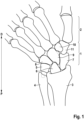
- the Figure 1 shows the anatomy around the wrist in a schematic way.
- the carpus 1 borders on the radius 3 and ulna 4.
- Distal D from the carpus 1 is the metacarpus 2.
- the carpus 1 has the bones Os triquetrum 5, Os lunatum 6 and Os scaphoideum 7.
- Distal D from three carpal bones 5, 6, 7 are the carpal bones Os hamatum 8, Os capitatum 9, Os trapezoid 10 and Os trapezium 11.
- a distal end region 29 with the most distal point 23 of the wrist arthrodesis plate 20 according to the invention can be placed on a single one of the four carpal bones: hamate bone 8, capitate bone 9, trapezoid bone 10 and trapezium bone 11.
- the bone plate does not extend into the metacarpal bone 2.
- the plate can lie over or on one of the other bones: triquetrum bone 5, lunate bone 6 or scaphoid bone 7, but is not attached to it.
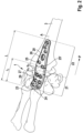
- Figure 2 shows a bone plate 20 according to the invention in the intended position.
- the plate 20 is made of pure titanium or a titanium alloy and has a longitudinal axis A. Along the longitudinal axis A, the plate has a length L of approximately 55 mm to 85 mm (see also Fig. 3a/3b and 4a/4b ). on.
- the plate 20 consists of a distal region 21 and a proximal region 22 adjacent in the proximal direction P.
- the distal region 21 has a length of 16 mm to 28 mm along the longitudinal axis A, depending on the type of treatment.
- the proximal region 22 has a length of approximately 40 mm to 50 mm along the longitudinal axis A.
- the proximal area 22 of the plate 20 lies on the radius 3 and can be attached to it.
- the distal area 21 lies on the carpus 1 and can be attached to it.
- the distal end area 29 has six plate holes 24 (denoted only once for reasons of clarity). Using screws (not shown), the distal end area 29 is attached through the plate holes 24 to a single carpal bone from the group of os hamatum 8, os capitatum 9, os trapezoid 10 and os trapezium 11 (see Fig. 1 ) without covering adjacent bones laterally.
- the proximal region 22 has several plate holes, specifically five round holes 25, 25 ⁇ (only partially designated for reasons of clarity) and an elongated hole 26 for fastening the proximal region with screws (not shown) to the radius 3.
- the distal region 21 of the plate therefore extends over the carpus 1.
- the distal end region 29, however, lies only on one of the carpal bones 8, 9, 10, 11 and is also only attached to this individual carpal bone 8, 9, 10, 11. No region of the plate is attached to or contacts the metacarpal 2.
- the distal region 21 has a saddle-shaped recess 27. Due to the recess 27, the plate 20 extends at the more distal end of the distal end region 29 at an angle of approximately 10° with respect to a more proximal region of the distal end region 29. This recess 27 increases the wearing comfort of the plate 20.
- the plate 20 has the widest point in the proximal region 22 with a width b2 of approximately 13.5 mm.
- the distal region has a maximum width b1 of also about 13.5 mm.
- the widths b1, b2 are measured on a line perpendicular to the longitudinal axis between the most lateral points, or their projections on an axis parallel to the longitudinal axis A.
- the distance l1 from the most distal plate hole 25 ⁇ of the proximal area 22 to the most distal point 23 is approximately 25 mm depending on the type of treatment (see the following description of a short plate in Figures 4a and 4b ) or 31 mm (see the following description of a long plate in Figures 3a and 3b ).
- the length l1 was drawn outside the plate for reasons of clarity. The length l1 is measured from a center of the most distal plate hole 25 ⁇ of the proximal area 22 on a direct path to the most distal point 23 of the plate 20.
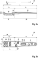
- Figure 3a shows a first embodiment of a plate 20 according to the invention in side view.
- This plate is intended for treatment while maintaining the proximal row of carpal bones or for large patients after a proximal row carpectomy.
- the plate In the proximal section 22 with a length 13 of approximately 43 mm, the plate runs in a first surface 30. Viewed from the distal end 23 in the proximal direction P, the plate 20 runs in the distal region 21 first in a second surface 31 which runs at an angle ⁇ with respect to the surface 30. Then the plate runs, still in the distal region, in a third surface 32 which runs approximately parallel to the first surface 30. The plate transitions from the third surface 32 to the first surface 30 via a fourth surface 33. The bend between the fourth surface 33 and the first surface 30 typically also defines the boundary between the proximal region 22, which can be placed on the radius, and the distal region 21. In the embodiment shown, the length 12 of the distal section 21 is 18-22 mm.
- angles ⁇ between the second surface 31 and the third surface 32 are approximately 45° and the angle ⁇ between the third surface 32 and the fourth surface 33 as well as the angle ⁇ between the fourth surface 33 and the first surface 30 are approximately 35°.
- first area 30 and the third area 32 are in Figure 3a approximately parallel to each other. However, it is also conceivable to provide a small angle between the first surface 30 and the third surface 32, for example an angle of up to 10°.
- Figure 3b shows a top view of the plate from Figure 3a .
- the various holes are shown, in particular plate holes 24 (in the distal region 21) and 25, 25' (in the proximal region 22) for receiving bone screws, a plate hole in the form of an elongated hole 26 and a hole 28 for receiving a K-wire.
- the plate In the proximal region, the plate has a maximum width b2 of approximately 13.5 mm and tapers in the proximal seal P.
- the plate has an essentially constant width b1 of also approximately 13.5 mm.
- FIGS. 4a and 4b show analogous to the Figures 3a and 3b an alternative embodiment of a plate according to the invention, which is suitable for the treatment of a normal-sized hand after a proximal row carpectomy or also a small hand without this procedure. Accordingly, the third surface 32 is missing, which in Figure 3a is visible: Instead, the plate according to the invention goes according to Figures 4a and 4b directly from the second surface 31 into the fourth surface 33. Accordingly, the length 12 of the distal section 21 is Figure 4a shorter as per Figure 3a and is typically 17mm. The length 13 of the proximal section 22 is, however, approximately the same in both embodiments. In the embodiment according to Figure 4a the second surface 31 merges into the fourth surface 33 in a slight radius. The angular position of the second surface 31 and the third surface 33 to each other and to the first surface 30 correspond approximately to the angular positions according to the embodiment of Figure 3a .
- the distance of the most distal plate hole 25' of the proximal part 22 (in Figures 3b and 4b designated l1) from the distal end 23 is typically 25 mm ( Figure 3a ) or 7 mm ( Figure 4a ) .
- the lengths of the second, third and fourth surfaces are typically between 7.5 mm and 10.0 mm.
- the length of the second surface is approximately 8.0 mm
- the length of the third surface is approximately 8.7 mm
- the length of the fourth surface is approximately 9.3 mm.
Landscapes
- Health & Medical Sciences (AREA)
- Orthopedic Medicine & Surgery (AREA)
- Life Sciences & Earth Sciences (AREA)
- Surgery (AREA)
- Animal Behavior & Ethology (AREA)
- Veterinary Medicine (AREA)
- Public Health (AREA)
- Engineering & Computer Science (AREA)
- Biomedical Technology (AREA)
- Heart & Thoracic Surgery (AREA)
- General Health & Medical Sciences (AREA)
- Molecular Biology (AREA)
- Medical Informatics (AREA)
- Nuclear Medicine, Radiotherapy & Molecular Imaging (AREA)
- Neurology (AREA)
- Cardiology (AREA)
- Oral & Maxillofacial Surgery (AREA)
- Transplantation (AREA)
- Vascular Medicine (AREA)
- Surgical Instruments (AREA)
Description
- Die Erfindung betrifft Handgelenksarthrodeseplatten gemäss den kennzeichnenden Teilen der unabhängigen Ansprüche.
- Eine Handgelenksarthrodese (Handgelenksversteifung) wird in der Regel bei schmerzhaften Endzuständen des Handgelenks angewandt. Solche Endzustände können ihre Ursache beispielsweise in sehr alten Kahnbeinfrakturen (Kahnbeinpseudarthrosen), im Spätstadium des Mondbeintodes (Lunatummalazie), oder in einem Zusammenbruch der Handwurzelknochen in Folge eines alten Bandrisses der Handgelenksbänder haben. Insbesondere kann eine Versteifung auch bei schmerzhafter Arthrose nach in Fehlstellung verheilten Speichenbrüchen oder bei fortgeschrittener, schmerzhafter Arthrose aus innerer Ursache erfolgen. Nach einer Handgelenksarthrodese ist das Handgelenk wieder schmerzfrei, jedoch versteift.
- Für eine Handgelenksarthrodese schlägt die
US 5,853,413 eine Platte vor, mit welcher der Radius (Speiche), mehrere Handwurzelknochen und ein Mittelhandknochen miteinander versteift werden. Mit der Zeit werden der Radius, die Handwurzelknochen und der Mittalhandknochen miteinander verschmelzen und das Handgelenk dadurch versteift. - Mit einer Platte nach
US 5,853,413 wird das Handgelenk relativ grossflächig versteift bzw. fusioniert, wodurch die Bewegungsfreiheit des Handgelenks des Patienten nach der Versteifung sehr eingeschränkt ist. - Der Anbieter Medartis schlägt im Katalog "Arthrodesen-System 2.0/ 2.3, 2.5" eine Platte vor, bei welcher mehrere Handwurzelknochen mit dem Radius versteift werden. Die Platte erstreckt sich anders als gemäss
US 5,853,413 jedoch nicht bis zu einem Mittelhandknochen. - Bei der vorgeschlagenen Platte wird das Handgelenk insgesamt zwar deutlich weniger versteift als bei einer Platte nach
US 5,853,413 . Allerdings ist die Bewegungsfreiheit des Handgelenks nach der Versteifung immer noch relativ stark eingeschränkt. - Eine Handgelenksarthrodeseplatte mit den Merkmalen des Oberbegriffs des Anspruchs 1 ist aus der
US 6 221 073 B1 bekannt. - Es ist daher eine Aufgabe der Erfindung, die Nachteile der bekannten Platten zu minimieren und insbesondere eine Platte bereitzustellen, welche ein schmerzfreies Handgelenk mit möglichst grosser Bewegungsfreiheit ermöglicht. Die Aufgabe wird durch die Merkmale der unabhängigen Ansprüche gelöst.
- Es wird eine Handgelenksarthrodeseplatte bestehend aus einem distalen und einem proximalen Bereich vorgeschlagen. Der proximale Bereich schliesst in Richtung einer Längsachse an den distalen Bereich an. Form und Grösse der Platte sind so ausgebildet, dass der distale Bereich der Platte an der Handwurzel und ein proximaler Bereich der Platte am Radius mit Hilfe von in Plattenlöchern einsetzbaren Befestigungsmitteln, insbesondere Schrauben, befestigbar sind. Form und Grösse eines distalen Endbereichs, welcher eine distalste Stelle der Platte umfasst, sind so ausgebildet, dass der distale Endbereich genau und nur an einem Knochen aus der distalen Reihe der Handwurzelknochen (d.h. Handwurzelknochen aus der Gruppe Os trapezium, Os trapezoideum, Os capitatum, und Os hamatum) anlegbar ist, ohne dabei einen Teil der lateral benachbarten Knochen zu überdecken.
- Eine erfindungsgemässe Platte erstreckt sich daher nicht bis zu den Mittelhandknochen. Dass der distale Endbereich genau einem Handwurzelknochen aus der Gruppe Os trapezium, Os trapezoideum, Os capitatum, und Os hamatum anlegbar ist, soll hier nicht so verstanden werden, dass der distale Bereich als Ganzes nicht über einen oder mehrere der weiteren Handwurzelknochen anliegt.
- Erfindungsgemäß ist ein distaler Bereich zusätzlich auch auf einem der Knochen Os scaphoideum, Os lunatum oder Os triquetrum (d.h. der proximalen Reihe der Handwurzelknochen) auflegbar und auf einem dieser Knochen auch verschraubbar. Allerdings liegt der distale Endbereich nicht auf einem der letztgenannten Knochen und wird auch nicht daran befestigt.
- Typischerweise kann die erfindungsgemässe Platte nach einer Entfernung der proximalen Reihe der Handwurzelknochen (Proximal Row Carpectomy) eingesetzt werden. In einem solchen Fall wird die erste, proximale Knochenreihe der Handwurzelknochen (Os scaphoidum, Os lunatum und Os triquetrum) entfernt. In diesem Fall ist die erfindungsgemässe Platte an nur genau einem der distalen Handwurzelknochen und insbesondere am Capitatum angelegt und befestigt.
- Mit der erfindungsgemässen Platte wird dann lediglich genau ein Handwurzelknochen aus der Gruppe Os trapezium, Os trapezoideum, Os capitatum, und Os hamatum mit dem Radius versteift. Dadurch kann trotz Versteifung eine relativ grosse Bewegungsfreiheit für den Patienten ermöglicht werden. Falls keine Proximal Row Carpectomy erfolgt, kann die Versteifung mit dem Radius und/oder mit einem Handwurzelknochen der proximalen Reihe erfolgen. Indem die Form und Grösse des distalen Bereichs erfindungsgemäss ausgewählt wird, ist es ermöglicht, dass die Platte nur an einem der genannten Knochen und insbesondere am Os capitatum anliegt und befestigt wird, ohne dass die Platte an benachbarte Knochen angelegt werden muss. Bevorzugt weist die distalste Stelle eine maximale Breite auf, die etwa der maximalen Breite eines menschlichen Capitatums entspricht.
- Benachbarte Handwurzelknochen aus der distalen Knochenreihe, also typischerweise Os hamatum und Os trapezoideum werden von der Platte nicht bedeckt.
- Der distale Bereich und insbesondere das distalste Ende hat bevorzugt eine Breite von 10 mm bis 15 mm, vorzugsweise 12 mm bis 14 mm, besonders bevorzugt etwa 13.5 mm. Die Breite des distalen Bereichs wird senkrecht zur Längsachse zwischen den zwei lateralsten Stellen des distalen Bereichs (bzw. deren Projektion parallel zur Längsachse) gemessen. Diese Breiten haben sich als vorteilhaft für eine genügende jedoch nicht zu einschränkende Versteifung herausgestellt. Diese Breite ist bevorzugt auch die grösste Breite der Platte insgesamt.
- Der distale Bereich hat bevorzugt eine Länge von 15 mm bis 30 mm, vorzugsweise 15 mm bis 20 mm oder 20 mm bis 27 mm, besonders bevorzugt 16-18 oder 21-24mm. Diese Längen ermöglichen eine Versteifung des Handgelenks, ohne dass sich die Platte in die Mittelhand erstreckt oder zu weit/zu wenig auf dem Radius des Patienten erstreckt. Eine zu kurze Länge kann zu einer unzulänglichen Versteifung führen. Eine zu lange Erstreckung kann sich negativ auf den Tragekomfort der Platte auswirken
- Je nach Indikation sind Platten mit unterschiedlichen Längen denkbar. Eine kürzere Platte kann zu der Versorgung nach einer proximal row carpectomy oder bei kleinen Patienten ohne proximal row carpectomy eingesetzt werden, eine längere Platte zur Versorgung unter Beibehalt der proximalen Reihe der Handwurzelknochen oder nach einer proximal row carpectomy bei grossen Patienten. Typischerweise ist die Länge des distalen Bereichs der oben genannten kürzeren Platte im bevorzugten Bereich von 15 mm bis 20 mm im Fall einer proximal row carpectomy bzw. beim kleinen Patienten. Die Länge des distalen Bereichs der längeren Platte beträgt 20 mm bis 27 mm im Fall einer Versorgung unter Beibehaltung der proximalen Knochenreihen bzw. beim grossen Patienten nach einer proximal row carpectomy.
- Ein distalstes Plattenloch des proximalen Bereichs kann maximal 20 mm bis 35 mm, vorzugsweise 22 mm bis 26 mm oder 30 mm bis 32 mm, von der distalsten Stelle der Platte beabstandet sein. Hier wird als Abstand vom distalsten Plattenloch des proximalen Bereichs bis zur distalsten Stelle der Platte die Länge einer direkten Strecke von einem Zentrum des Plattenlochs bis zur distalsten Stelle der Platte verstanden.
- Auch hier beziehen sich die vorgenannten kürzeren und längeren Abstände auf eine Versorgung unter Entfernung beziehungsweise unter Beibehaltung der proximalen Knochenreihe bzw. bei kleinen oder grossen Patienten.
- Vorzugsweise weist die Platte eine Gesamtlänge entlang der Längsachse im Bereich von 55 bis 85 mm, vorzugsweise je nach Art der Versorgung vom 59 mm bis 62 mm bzw. 65 mm bis 68 mm auf.
- Dieser Längenbereich hat sich als vorteilhaft herausgestellt, um eine hinreichende Versteifung zwischen Handwurzelknochen und Radius zu erreichen, ohne dass die Bewegungsfreiheit übermässig eingeschränkt wird.
- Der proximale Bereich weist vorzugsweise eine Länge von 35 bis 60 mm, vorzugsweise 40mm bis 50 mm, auf. Im proximalen Bereich kann die Platte aber auch länger ausgebildet sein, ohne die bestimmungsgemässe Funktion zu beeinträchtigen.
- Vorzugsweise verläuft die Platte in Längsrichtung zumindest in einer ersten Fläche oder mit einer ersten Tangente entlang der Längsachse und in Längsrichtung zusätzlich in einer zur ersten Fläche oder ersten Tangente unter einem Winkel verlaufenden zweiten Fläche oder zweiten Tangente entlang der Längsachse.
- Die Platte kann ausserdem in Längsrichtung in einer zur ersten Fläche beabstandeten und dazu etwa parallelen dritten Fläche verlaufen.
- Diese Ausführungsform ist insbesondere im Zusammenhang mit der vorstehend beschriebenen längeren Platte für eine Versorgung unter Beibehaltung der proximalen Reihe der Handwurzelknochen bevorzugt.
- Die zweite Fläche oder die zweite Tangente weist bevorzugt einen Winkel von etwa 45° zur ersten Fläche auf und/oder verläuft über eine Länge von 7.5 mm bis 8.5 mm, vorzugsweise 8.0 mm. Die Platte verläuft ausserdem in einer bevorzugten Ausführungsform nach der zweiten Fläche in proximaler Richtung in der dritten Fläche, oder der drittem Tangente entlang der Längsachse, insbesondere über eine Länge von 8.0 mm bis 9.0 mm, vorzugsweise 8.5 mm.
- Nach der zweiten Fläche oder nach der dritten Fläche kann die Platte in proximaler Richtung in einer vierten Fläche, oder entlang einer vierten Tangente in die erste Fläche übergehen, wobei die vierte Fläche oder die vierte Tangente bevorzugt einen Winkel von etwa 35° zur ersten Fläche aufweist und/oder über eine Länge von 8.5 mm bis 9.5 mm, vorzugsweise 9.3 mm verläuft. Vorliegend wird auf Flächen verwiesen. Die Flächen verlaufen typischerweise je im Wesentlichen in einer Ebene.
- Im Fall einer kurzen Platte für eine Versorgung bei einer proximal row carpectomy oder kleinen Patienten erfolgt der Übergang direkt von der zweiten in die vierte Ebene. Im Fall einer Versorgung unter Beibehaltung der proximalen Knochenreihe oder beim grossen Patienten befindet sich zwischen der zweiten und der vierten Ebene die dritte Ebene.
- Es versteht sich von selbst, dass die genannten Flächen nicht vollständig planar sein müssen. Eine oder mehrere Krümmungen sind denkbar. Aus diesem Grund wird vorstehend jeweils auf Flächen oder Tangenten verwiesen.
- Ein derartiger Verlauf mit mehreren Flächen/Tangenten entlang der Längsrichtung ermöglicht eine gute Anpassung der Platte an die Anatomie der Handwurzelknochen. Insbesondere ermöglicht eine leicht abgerundete Sattelform im distalen Bereich, dass der distale Bereich gut an der Handwurzel aufliegt. Alternativ zur Sattelform ist es auch denkbar, dass zumindest planar verlaufende Abschnitte, welche einen Winkel bilden, in Längsrichtung vorhanden sind. Es sind aber auch vollständig flache Platten denkbar.
- Vorzugsweise weist der proximale Bereich der Platte eine maximale Breite von 8 bis 20 mm, vorzugsweise 9 mm bis 15 mm, besonders bevorzugt 13.5, auf. Als Breite wird wiederum eine senkrecht zur Längsachse gemessene Distanz zwischen den zwei lateralsten Stellen des proximalen Bereichs (bzw. deren Projektion parallel zur Längsachse) verstanden.
- Vorzugsweise weist der distale Bereich in Draufsicht gesehen nebeneinander (d.h. innerhalb eines Winkelbereichs von +/-45° bezogen auf eine Achse etwa senkrecht zur Längsachse A) je maximal zwei, vorzugsweise genau zwei, Plattenlöcher zur Befestigung der Platte an dem genau einen Handwurzelknochen auf.
- Zwei Plattenlöcher, welche in Draufsicht gesehen nebeneinander liegen, ermöglichen eine sichere Befestigung des distalen Endbereichs an einem einzigen Handwurzelknochen.
- Vorzugsweise weist der distale Endbereich maximal sechs, vorzugsweise genau sechs, Plattenlöcher zur Aufnahme von Knochenschrauben zur Befestigung der Platte am Handwurzelknochen auf. Selbstverständlich kann die Platte daneben weitere Löcher, z.B. für einen K-Draht, aufweisen. Die distalen vier Plattenlöcher sind für das Capitatum gedacht, die proximalen zwei Plattenlöcher für das Lunatum. Bei einer grossen Hand und einer proximal row carpectomy wird eine kurze Platte verwendet und es werden bis zu sechs Schrauben in das Capitatum geschraubt. Bei einer kleinen Hand ohne proximal row carpectomy wird eine kurze Platte verwendet und Capitatum und Lunatum verschraubt.
- Die Plattenlöcher können bevorzugt mit einer dem Fachmann an sich bekannten Verblockungskontur versehen sein, welche die winkelstabile Befestigung von Knochenschrauben ermöglicht. Solche Konturen sind beispielsweise aus
WO 2004/086990 A1 bekannt. - Alternativ ist auch eine andere Anzahl Plattenlöcher, wie beispielsweise drei, vier oder fünf Plattenlöcher im distalen Bereich möglich.
- Der proximale Bereich weist vorzugsweise zumindest zwei, vorzugsweise drei, vier, fünf, sechs, sieben, acht, neun oder zehn, oder mehr Plattenlöcher in Form von Rund- oder Langlöchern für Knochenschrauben auf. Bevorzugt sind mehrere Rundlöcher und ein Langloch.
- Auch im proximalen Bereich können die Plattenlöcher für Knochenschrauben mit Verblockungskonturen versehen sein und/oder es können Löcher für K-Drähte vorgesehen werden.
- Dadurch kann der proximale Bereich sicher am Radius befestigt werden.
- Es sind auch mehr als zehn Plattenlöcher und/oder mehr oder weniger als ein Plattenloch in Form eines Langlochs im proximalen Bereich denkbar.
- Vorzugsweise beinhaltet die Platte Titan oder besteht die Platte aus Titan. Titan(legierungen) sind biokompatibel und widerstandsfähig und haben sich als optimal für Knochenplatten herausgestellt.
- Andere biokompatible Materialien, wie andere Metalle/Metalllegierungen oder Kunststoffe sind auch denkbar.
- Eine Befestigung an genau einem Handwurzelknochen pro Reihe erreicht eine genügende, jedoch nicht zu grossflächige Versteifung.
- Erfindungsgemäß wird die Platte an keinem Mittelhandknochen befestigt. Zudem wird die Platte nicht an zwei lateral nebeneinander liegenden Handwurzelknochen, sondern lediglich maximal an zwei in Längsrichtung liegenden Handwurzelknochen, befestigt.
- Weitere Merkmale der Erfindung sind den nachfolgenden Figuren zu entnehmen. Es zeigen schematisch:
-
Fig. 1 : Die Anatomie um das Handgelenk; -
Fig. 2 : Eine erfindungsgemässe Handgelenksarthrodeseplatte, -
Figur 3a : Eine Seitenansicht einer ersten erfindungsgemässen Handgelenksarthrodeseplatte, -
Figur 3b : Draufsicht auf die Platte gemässFigur 3a , -
Figur 4a : Eine Seitenansicht einer alternativen Ausführungsform einer erfindungsgemässen Handgelenksarthrodeseplatte und, -
Figur 4b : Eine Draufsicht auf die Platte gemässFigur 4a . - Die
Figur 1 zeigt schematisch die Anatomie um das Handgelenk. In proximaler Richtung P grenzt die Handwurzel 1 an Radius 3 und Ulna 4 an. Distal D von der Handwurzel 1 liegt die Mittelhand 2. Die Handwurzel 1 weist die Knochen Os triquetrum 5, Os lunatum 6 und Os scaphoideum 7 auf. Distal D von drei Handwurzelknochen 5, 6, 7 liegend befinden sich die Handwurzelknochen Os hamatum 8, Os capitatum 9, Os trapezoideum 10 und Os trapezium 11. Ein distaler Endbereich 29 mit der distalsten Stelle 23 der erfindungsgemässen Handgelenksarthrodeseplatte 20 (sieheFigur 2 ) ist auf einem einzigen der vier Handwurzelknochen Os hamatum 8, Os capitatum 9, Os trapezoideum 10 und Os trapezium 11 anlegbar. Die Knochenplatte erstreckt sich nicht bis in die Mittelhand 2. Zwischen dem proximalen Bereich 22 und den distalen Stellen 23 kann die Platte über oder an einem der weiteren Knochen Os triquetrum 5, Os lunatum 6 oder Os scaphoideum 7 liegen, ohne aber daran befestigt zu sein. -
Figur 2 zeigt eine erfindungsgemässe Knochenplatte 20 in bestimmungsgemässer Lage. Die Platte 20 ist aus Reintitan oder einer Titanlegierung gefertigt und weist eine Längsachse A auf. Entlang der Längsachse A weist die Platte eine Länge L von etwa 55 mm bis 85 mm auf (siehe dazu auchFig. 3a/3b und4a/4b ). auf. - Die Platte 20 besteht aus einem distalen Bereich 21 und einem in proximaler Richtung P angrenzenden proximalen Bereich 22. Der distale Bereich 21 hat entlang der Längsachse A je nach Art der Versorgung eine Länge von 16 mm bis 28 mm. Der proximale Bereich 22 hat entlang der Längsachse A eine Länge von ca. 40 mm bis 50mm.
- Der proximale Bereich 22 der Platte 20 liegt auf dem Radius 3 und ist daran befestigbar. Der distale Bereich 21 liegt auf der Handwurzel 1 und ist daran befestigbar. Der distale Endbereich 29 weist sechs Plattenlöcher 24 (aus Gründen der Übersicht nur einmal bezeichnet) auf. Mit Schrauben (nicht gezeigt), ist der distale Endbereich 29 durch die Plattenlöcher 24 an einen einzigen Handwurzelknochen aus der Gruppe Os hamatum 8, Os capitatum 9, Os trapezoideum 10 und Os trapezium 11 (siehe
Fig. 1 ) befestigbar, ohne dass lateral benachbarte Knochen bedeckt werden. Der proximale Bereich 22 weist mehrere Plattenlöcher auf, konkret fünf Rundlöcher 25, 25` (aus Gründen der Übersicht nur teilweise bezeichnet) und ein Langloch 26 zur Befestigung des proximalen Bereichs mit Schrauben (nicht gezeigt) am Radius 3 auf. - Der distale Bereich 21 der Platte erstreckt sich daher über die Handwurzel 1. Der distale Endbereich 29 liegt jedoch nur auf einem der Handwurzelknochen 8, 9, 10, 11 und wird auch nur an diesem einzelnen Handwurzelknochen 8, 9, 10, 11 befestigt. Kein Bereich der Platte wird an der Mittelhand 2 befestigt oder kontaktiert diese.
- Der distale Bereich 21 weist eine sattelförmige Vertiefung 27 auf. Aufgrund der Vertiefung 27 verläuft die Platte 20 am distaleren Ende des distalen Endbereichs 29 in einem Winkel von etwa 10° bezüglich eines proximaleren Bereichs des distalen Endbereichs 29. Durch diese Vertiefung 27 wird der Tragekomfort der Platte 20 erhöht.
- Die Platte 20 weist im proximalen Bereich 22 die breiteste Stelle mit einer Breite b2 von etwa 13.5 mm auf. Der distale Bereich hat eine maximale Breite b1 von ebenfalls etwa 13.5 mm. Die Breiten b1, b2 bemessen sich auf einer Strecke senkrecht zur Längsachse zwischen den lateralsten Stellen, bzw. deren Projektionen auf einer Achse parallel zur Längsachse A.
- Der Abstand l1 vom distalsten Plattenloch 25` des proximalen Bereichs 22 bis zur distalsten Stelle 23 ist je nach Art der Versorgung etwa 25 mm (siehe nachfolgende Beschreibung einer kurzen Platte in
Figuren 4a und 4b ) oder 31 mm (siehe nachfolgende Beschreibung einer langen Platte inFiguren 3a und 3b ). Die Länge l1 wurde aus Übersichtsgründen ausserhalb der Platte eingezeichnet. Die Länge l1 bemisst sich von einem Zentrum des distalsten Plattenlochs 25` des proximalen Bereichs 22 auf direktem Weg zur distalsten Stelle 23 der Platte 20. -
Figur 3a zeigt eine erste Ausführungsform einer erfindungsgemässen Platte 20 in Seitenansicht. Diese Platte ist für eine Versorgung unter Beibehaltung der proximalen Reihe der Handwurzelknochen oder für grosse Patienten nach einer proximal row carpectomy vorgesehen. Im proximalen Abschnitt 22 mit einer Länge 13 von ca. 43 mm verläuft die Platte in einer ersten Fläche 30. Vom distalsten Ende 23 her in proximaler Richtung P betrachtet verläuft die Platte 20 im distalen Bereich 21 zuerst in einer bezogen auf die Fläche 30 unter einem Winkel α verlaufenden zweiten Fläche 31. Anschliessend verläuft die Platte immer noch im distalen Bereich in einer dritten Fläche 32, welche etwa parallel zur ersten Fläche 30 verläuft. Über eine vierte Fläche 33 geht die Platte von der dritten Fläche 32 in die erste Fläche 30 über. Der Knick zwischen der vierten Fläche 33 und der ersten Fläche 30 definiert typischerweise auch die Abgrenzung zwischen dem proximalen Bereich 22, welcher auf dem Radius anlegbar ist und dem distalen Bereich 21. Im gezeigten Ausführungsbeispiel beträgt die Länge 12 des distalen Abschnitts 21 18-22 mm. - In
Figur 3a betragen die Winkel α zwischen der zweiten Fläche 31 und der dritten Fläche 32 etwa 45° und der Winkel β zwischen der dritten Fläche 32 und der vierten Fläche 33 sowie der Winkel γ zwischen der vierten Fläche 33 und der ersten Fläche 30 etwa 35°. - Im konkreten Beispiel sind die erste Fläche 30 und die dritte Fläche 32 in
Figur 3a etwa parallel zueinander. Es ist aber auch denkbar, einen kleinen Winkel zwischen erster Fläche 30 und dritter Fläche 32 vorzusehen, beispielsweise einen Winkel von bis zu 10°. -
Figur 3b zeigt eine Draufsicht auf die Platte ausFigur 3a . Gleiche Bezugszeichen bezeichnen gleiche Teile. InFigur 3b sind zusätzlich die verschiedenen Löcher, insbesondere Plattenlöcher 24 (im distalen Bereich 21) und 25, 25` (im proximalen Bereich 22) zur Aufnahme von Knochenschrauben, ein Plattenloch in Form eines Langlochs 26 sowie ein Loch 28 zur Aufnahme eines K-Drahts gezeigt. Im proximalen Bereich weist die Platte eine maximale Breite b2 von etwa 13.5 mm auf und verjüngt sich in proximaler Dichtung P. Im distalen Bereich 21 weist die Platte eine im wesentlichen konstante Breite b1 von ebenfalls etwa 13,5 mm auf. - Die
Figuren 4a und 4b zeigen analog zu denFiguren 3a und 3b eine alternative Ausführungsform einer erfindungsgemässen Platte, welche für eine Versorgung einer normal grossen Hand nach einer proximal row carpectomy oder auch einer kleinen Hand ohne diesen Eingriff geeignet ist. Entsprechend fehlt die dritte Fläche 32, welche inFigur 3a sichtbar ist: Stattdessen geht die erfindungsgemässe Platte gemässFiguren 4a und 4b unmittelbar von der zweiten Fläche 31 in die vierte Fläche 33 über. Entsprechend ist die Länge 12 des distalen Abschnitts 21 gemässFigur 4a kürzer als gemässFigur 3a und beträgt typischerweise 17mm. Die Länge 13 des proximalen Abschnitts 22 ist hingegen in beiden Ausführungsformen etwa gleich. Im Ausführungsbeispiel gemässFigur 4a geht die zweite Fläche 31 in einem leichten Radius in die vierte Fläche 33 über. Die Winkellage der zweiten Fläche 31 und der dritten Fläche 33 zueinander und gegenüber der ersten Fläche 30 entsprechen ungefähr den Winkellagen gemäss dem Ausführungsbeispiel vonFigur 3a . - Der Abstand des distalsten Plattenlochs 25' des proximalen Teils 22 (in
Figuren 3b und4b mit l1 bezeichnet) vom distalsten Ende 23 beträgt typischerweise 25 mm (Figur 3a ) oder 7 mm (Figur 4a ) . - Die Längen der zweiten, dritten und vierten Flächen betragen typischerweise zwischen 7.5 mm und 10.0 mm. Im konkreten Ausführungsbeispiel beträgt die Länge der zweiten Fläche etwa 8.0 mm, die Länge der dritten Fläche etwa 8.7 mm und die Länge der vierten Fläche etwa 9.3 mm.
Claims (14)
- Handgelenksarthrodeseplatte (20) bestehend aus einem distalen (21) und einem proximalen (22) Bereich, welcher in Richtung einer Längsachse (A) an den distalen Bereich (21) anschliesst,wobei Form und Grösse der Platte (20) so ausgebildet sind, dass der distale Bereich (21) der Platte an der Handwurzel (1) und der proximale Bereich (22) der Platte am Radius (3) mit Hilfe von in Plattenlöchern einsetzbaren Befestigungsmitteln, insbesondere Schrauben, befestigbar sind, wobei Form und Grösse eines distalen Endbereichs (29), welcher eine distalste Stelle (23) der Platte (20) umfasst, so ausgebildet sind, dass der distale Endbereich (29) genau und nur an einem Handwurzelknochen aus der Gruppe Os trapezium (11), Os trapezoideum (10), Os capitatum (9), und Os hamatum (8) anlegbar ist, ohne dabei einen Teil der lateral benachbarten Knochen zu überdecken, dadurch gekennzeichnet dass, der distale Bereich (21) auf einem proximalen Handwurzelknochen der proximalen Reihe der Handwurzelknochen bestehend aus Os scaphoideum (7), Os lunatum (6), und Os triquetrum (5) auflegbar ist und auf diesem Handwurzelknochen verschraubbar ist, wobeider distale Bereich (21) an höchstens einem der proximalen Handwurzelknochen befestigbar ist, wobeidie Platte (20) höchstens an zwei Handwurzelknochen entlang einer Längslinie und an keinem Mittelhandknochen befestigbar ist.
- Platte (20) nach Anspruch 1, wobei die distalste Stelle (23) eine maximale Breite (b1) aufweist, die etwa der maximalen Breite eines menschlichen Capitatums entspricht.
- Platte (20) nach einem der der vorhergehenden Ansprüche, wobei der distale Bereich (21) und insbesondere das distalste Ende (23) eine Breite (b1) von 10 mm bis 15 mm, bevorzugt 12 mm bis 14 mm, vorzugsweise 13.5 mm aufweist.
- Platte (20) nach einem der vorhergehenden Ansprüche, wobei der distale Bereich (21) eine Länge (l2) von 15 mm bis 30 mm, vorzugsweise 15 mm bis 20 mm oder 20 mm bis 27 mm, aufweist.
- Platte (20) nach einem der vorhergehenden Ansprüche, wobei ein distalstes Plattenloch (25') des proximalen Bereichs (22) einen Abstand (l1) von maximal 20 mm bis 35 mm, vorzugsweise 22 mm bis 26 mm oder 30 mm bis 32 mm, von der distalsten Stelle (23) der Platte aufweist.
- Platte (20) nach einem der vorhergehenden Ansprüche, wobei die Platte eine Länge (L) entlang der Längsachse (A) im Bereich von 55 bis 85 mm, vorzugsweise 59 mm bis 62 mm oder 65 mm bis 68 mm aufweist.
- Platte (20) nach einem der vorhergehenden Ansprüche, wobei der proximale Bereich (22) eine Länge(13) von 35 bis 60 mm, vorzugsweise 40mm bis 50 mm, aufweist.
- Platte (20) nach einem der vorhergehenden Ansprüche, wobei die Platte (20) in Längsrichtung zumindest in einer ersten Fläche (30) oder mit einer ersten Tangente entlang der Längsachse (A) verläuft und in einer zur ersten Fläche (30) oder ersten Tangente unter einem Winkel (α)verlaufenden zweiten Fläche (31) oder zweiten Tangente entlang der Längsachse (A) verläuft.
- Platte (20) nach einem der vorhergehenden Ansprüche, wobei die Platte (20) in Längsrichtung in einer zur ersten Fläche (30) beabstandeten und dazu im Wesentlichen parallelen dritten Fläche (32) verläuft.
- Platte (20) nach einem der Ansprüche 8 oder 9, wobei der Winkel (α) zwischen der zweiten Fläche (31) oder der zweiten Tangente und der ersten Fläche (30) oder ersten Tangente etwa 45° beträgt und/oder die zweite Fläche (31) über eine Länge von 7.5 mm bis 8.5 mm, vorzugsweise 8.0 mm verläuft.
- Platte (20) nach Anspruch 10, wobei die Platte (20) nach der zweiten Fläche (31) in proximaler Richtung (P) in der dritten Fläche (32) oder der dritten Tangente entlang der Längsachse (A) verläuft, insbesondere über eine Länge von 8.0 mm bis 9.0 mm, vorzugsweise 8.5 mm.
- Platte nach Anspruch 10 oder 11, wobei die Platte (20) nach der zweiten Fläche (31) oder nach der dritten Fläche (32) in proximaler Richtung (P) in einer vierten Fläche (33) oder entlang einer vierten Tangente in die erste Fläche (30) übergeht, wobei die vierte Fläche (33) oder die vierte Tangente bevorzugt einen Winkel (γ) von etwa 35° zur ersten Fläche aufweist und/oder über eine Länge von 8.5 mm bis 9.5 mm, vorzugsweise 9.3 mm verläuft.
- Platte (20) nach einem der vorhergehenden Ansprüche, wobei der proximale Bereich (22) der Platte (20) eine maximale Breite (b2) von 8 bis 20 mm, vorzugsweise 9 mm bis 15 mm besonders bevorzugt 13.5 mm aufweist.
- Platte (20) nach einem der vorhergehenden Ansprüche, wobei die Platte (20) Titan beinhaltet oder aus Titan besteht.
Applications Claiming Priority (2)
| Application Number | Priority Date | Filing Date | Title |
|---|---|---|---|
| EP18158329.5A EP3530224A1 (de) | 2018-02-23 | 2018-02-23 | Handgelenksarthrodeseplatte |
| PCT/EP2019/052899 WO2019162091A1 (de) | 2018-02-23 | 2019-02-06 | Handgelenksarthrodeseplatte und verfahren mit einer handgelenksarthrodeseplatte |
Publications (3)
| Publication Number | Publication Date |
|---|---|
| EP3755252A1 EP3755252A1 (de) | 2020-12-30 |
| EP3755252C0 EP3755252C0 (de) | 2024-11-06 |
| EP3755252B1 true EP3755252B1 (de) | 2024-11-06 |
Family
ID=61521300
Family Applications (2)
| Application Number | Title | Priority Date | Filing Date |
|---|---|---|---|
| EP18158329.5A Withdrawn EP3530224A1 (de) | 2018-02-23 | 2018-02-23 | Handgelenksarthrodeseplatte |
| EP19704290.6A Active EP3755252B1 (de) | 2018-02-23 | 2019-02-06 | Handgelenksarthrodeseplatte |
Family Applications Before (1)
| Application Number | Title | Priority Date | Filing Date |
|---|---|---|---|
| EP18158329.5A Withdrawn EP3530224A1 (de) | 2018-02-23 | 2018-02-23 | Handgelenksarthrodeseplatte |
Country Status (7)
| Country | Link |
|---|---|
| US (1) | US11660130B2 (de) |
| EP (2) | EP3530224A1 (de) |
| JP (1) | JP7402809B2 (de) |
| CN (1) | CN111757709B (de) |
| AU (1) | AU2019223652B2 (de) |
| MX (1) | MX2020008805A (de) |
| WO (1) | WO2019162091A1 (de) |
Families Citing this family (2)
| Publication number | Priority date | Publication date | Assignee | Title |
|---|---|---|---|---|
| JP7542632B2 (ja) * | 2020-02-07 | 2024-08-30 | トライメッド インク. | 少なくとも2つの骨構成要素を癒合するためのインプラント及びこのインプラントを使用して骨構成要素を癒合する方法 |
| WO2026090233A1 (en) * | 2024-10-22 | 2026-04-30 | Arthrex, Inc. | Pancarpal arthrodesis implants |
Citations (1)
| Publication number | Priority date | Publication date | Assignee | Title |
|---|---|---|---|---|
| US6221073B1 (en) * | 1999-08-20 | 2001-04-24 | Kinetikos Medical, Inc. | Wrist fusion apparatus and method |
Family Cites Families (17)
| Publication number | Priority date | Publication date | Assignee | Title |
|---|---|---|---|---|
| US5853413A (en) | 1997-04-18 | 1998-12-29 | Bristol-Myers Squibb Company | Wrist fusion plate |
| US6712820B2 (en) * | 2000-02-01 | 2004-03-30 | Hand Innovations, Inc. | Fixation plate system for dorsal wrist fracture fixation |
| US6358250B1 (en) * | 2000-02-01 | 2002-03-19 | Hand Innovations, Inc. | Volar fixation system |
| ATE450221T1 (de) | 2003-04-03 | 2009-12-15 | Medartis Ag | Aufnahme für ein verblockungselement und verblockungselement |
| US8021402B2 (en) * | 2006-03-07 | 2011-09-20 | Orthohelix Surgical Designs, Inc. | Distal radius plate |
| US8808334B2 (en) * | 2006-03-07 | 2014-08-19 | Orthohelix Surgical Designs, Inc. | Orthopedic plate |
| US20090248084A1 (en) * | 2008-03-27 | 2009-10-01 | Beat Hintermann | Systems and methods for performing ankle arthrodesis in a human patient |
| SE532458C2 (sv) * | 2008-07-01 | 2010-01-26 | Swemac Innovation Ab | Fixeringssystem |
| DE102008039693A1 (de) * | 2008-08-26 | 2010-03-11 | Normed Medizin-Technik Vertriebs-Gmbh | Handgelenkarthrodeseplatte sowie Sortiment |
| US20130006246A1 (en) * | 2011-06-30 | 2013-01-03 | Dodson Mark | Distal Radius Plate |
| DE202011051165U1 (de) | 2011-08-31 | 2011-11-14 | Merete Medical Gmbh | Anatomisch angepasste, plantare Knochenplatte sowie Knochenplattensystem |
| WO2013036362A1 (en) * | 2011-09-06 | 2013-03-14 | Synthes Usa, Llc | Pancarpal arthrodesis bone plate |
| WO2013045713A1 (es) * | 2011-09-26 | 2013-04-04 | Servicio Andaluz De Salud | Dispositivo de artrodesis parcial del carpo |
| US9320554B2 (en) * | 2011-12-22 | 2016-04-26 | Stryker European Holdings I, Llc | Wrist fusion plate |
| US8790378B2 (en) * | 2012-02-02 | 2014-07-29 | Biomet C.V. | Distal radius fracture fixation plate with integrated and adjustable volar ulnar facet support |
| US10376367B2 (en) * | 2015-07-02 | 2019-08-13 | First Ray, LLC | Orthopedic fasteners, instruments and methods |
| JP2017153816A (ja) * | 2016-03-03 | 2017-09-07 | 国立大学法人 新潟大学 | 骨固定プレート、骨固定装置 |
-
2018
- 2018-02-23 EP EP18158329.5A patent/EP3530224A1/de not_active Withdrawn
-
2019
- 2019-02-06 JP JP2020544455A patent/JP7402809B2/ja active Active
- 2019-02-06 CN CN201980014784.4A patent/CN111757709B/zh not_active Expired - Fee Related
- 2019-02-06 AU AU2019223652A patent/AU2019223652B2/en active Active
- 2019-02-06 US US16/970,734 patent/US11660130B2/en active Active
- 2019-02-06 EP EP19704290.6A patent/EP3755252B1/de active Active
- 2019-02-06 WO PCT/EP2019/052899 patent/WO2019162091A1/de not_active Ceased
- 2019-02-06 MX MX2020008805A patent/MX2020008805A/es unknown
Patent Citations (1)
| Publication number | Priority date | Publication date | Assignee | Title |
|---|---|---|---|---|
| US6221073B1 (en) * | 1999-08-20 | 2001-04-24 | Kinetikos Medical, Inc. | Wrist fusion apparatus and method |
Also Published As
| Publication number | Publication date |
|---|---|
| EP3755252A1 (de) | 2020-12-30 |
| CN111757709A (zh) | 2020-10-09 |
| AU2019223652B2 (en) | 2024-10-31 |
| AU2019223652A1 (en) | 2020-07-30 |
| WO2019162091A1 (de) | 2019-08-29 |
| BR112020014332A2 (pt) | 2020-12-08 |
| US20200375640A1 (en) | 2020-12-03 |
| JP7402809B2 (ja) | 2023-12-21 |
| EP3530224A1 (de) | 2019-08-28 |
| EP3755252C0 (de) | 2024-11-06 |
| CN111757709B (zh) | 2023-03-10 |
| JP2021514720A (ja) | 2021-06-17 |
| US11660130B2 (en) | 2023-05-30 |
| MX2020008805A (es) | 2020-10-14 |
Similar Documents
| Publication | Publication Date | Title |
|---|---|---|
| DE69620930T2 (de) | Platte und Stift | |
| EP0515828B1 (de) | Trochanterstabilisierungsvorrichtung | |
| DE69805219T2 (de) | Totale Ellbogenprothese | |
| DE19603285B4 (de) | Intramedullärer Nagel | |
| DE60013356T2 (de) | Humerusprothese | |
| DE69720485T2 (de) | Schulterprothese | |
| DE60210134T2 (de) | Befestigungsvorrichtung | |
| DE60107882T2 (de) | Schulterendoprothese für Brüche des oberen Endes des Oberarmknochens | |
| EP1713421B1 (de) | Zwischenwirbelimplantat zur spondylodese der lendenwirbelsäule | |
| EP1691701A1 (de) | Osteosyntheseplatten-set | |
| EP0402810B1 (de) | Implantationssatz | |
| DE3247726C2 (de) | ||
| DE69103895T2 (de) | Hüftprothese. | |
| EP0622056A2 (de) | Implantierbares Verankerungsorgan zur Aufnahme von Prothesen u.dgl. | |
| WO2001019268A1 (de) | Fixationssystem für knochen | |
| DE2941266A1 (de) | Hueftgelenksendoprothese | |
| DE2805305A1 (de) | Kuenstliches hueftgelenk | |
| EP2158864A2 (de) | Handgelenkarthrodeseplatte sowie Sortiment | |
| DE69917011T2 (de) | Handgelenkprothese | |
| DE10335388A1 (de) | Chirurgische Referenzierungsvorrichtung | |
| WO2019162091A1 (de) | Handgelenksarthrodeseplatte und verfahren mit einer handgelenksarthrodeseplatte | |
| DE202009008872U1 (de) | Fußchirurgie-Knochenplatte | |
| DE102005027283B4 (de) | Implantat zum Einfügen zwischen benachbarten Wirbelkörpern | |
| EP3616636B1 (de) | Knochenplatte und chirurgische sets | |
| DE69806828T2 (de) | Knöchelprothese |
Legal Events
| Date | Code | Title | Description |
|---|---|---|---|
| STAA | Information on the status of an ep patent application or granted ep patent |
Free format text: STATUS: UNKNOWN |
|
| STAA | Information on the status of an ep patent application or granted ep patent |
Free format text: STATUS: THE INTERNATIONAL PUBLICATION HAS BEEN MADE |
|
| PUAI | Public reference made under article 153(3) epc to a published international application that has entered the european phase |
Free format text: ORIGINAL CODE: 0009012 |
|
| STAA | Information on the status of an ep patent application or granted ep patent |
Free format text: STATUS: REQUEST FOR EXAMINATION WAS MADE |
|
| 17P | Request for examination filed |
Effective date: 20200720 |
|
| AK | Designated contracting states |
Kind code of ref document: A1 Designated state(s): AL AT BE BG CH CY CZ DE DK EE ES FI FR GB GR HR HU IE IS IT LI LT LU LV MC MK MT NL NO PL PT RO RS SE SI SK SM TR |
|
| AX | Request for extension of the european patent |
Extension state: BA ME |
|
| DAV | Request for validation of the european patent (deleted) | ||
| DAX | Request for extension of the european patent (deleted) | ||
| STAA | Information on the status of an ep patent application or granted ep patent |
Free format text: STATUS: EXAMINATION IS IN PROGRESS |
|
| 17Q | First examination report despatched |
Effective date: 20230220 |
|
| GRAP | Despatch of communication of intention to grant a patent |
Free format text: ORIGINAL CODE: EPIDOSNIGR1 |
|
| STAA | Information on the status of an ep patent application or granted ep patent |
Free format text: STATUS: GRANT OF PATENT IS INTENDED |
|
| INTG | Intention to grant announced |
Effective date: 20240117 |
|
| GRAJ | Information related to disapproval of communication of intention to grant by the applicant or resumption of examination proceedings by the epo deleted |
Free format text: ORIGINAL CODE: EPIDOSDIGR1 |
|
| STAA | Information on the status of an ep patent application or granted ep patent |
Free format text: STATUS: EXAMINATION IS IN PROGRESS |
|
| INTC | Intention to grant announced (deleted) | ||
| GRAP | Despatch of communication of intention to grant a patent |
Free format text: ORIGINAL CODE: EPIDOSNIGR1 |
|
| STAA | Information on the status of an ep patent application or granted ep patent |
Free format text: STATUS: GRANT OF PATENT IS INTENDED |
|
| INTG | Intention to grant announced |
Effective date: 20240607 |
|
| GRAS | Grant fee paid |
Free format text: ORIGINAL CODE: EPIDOSNIGR3 |
|
| GRAA | (expected) grant |
Free format text: ORIGINAL CODE: 0009210 |
|
| STAA | Information on the status of an ep patent application or granted ep patent |
Free format text: STATUS: THE PATENT HAS BEEN GRANTED |
|
| AK | Designated contracting states |
Kind code of ref document: B1 Designated state(s): AL AT BE BG CH CY CZ DE DK EE ES FI FR GB GR HR HU IE IS IT LI LT LU LV MC MK MT NL NO PL PT RO RS SE SI SK SM TR |
|
| REG | Reference to a national code |
Ref country code: GB Ref legal event code: FG4D Free format text: NOT ENGLISH |
|
| REG | Reference to a national code |
Ref country code: CH Ref legal event code: EP |
|
| REG | Reference to a national code |
Ref country code: DE Ref legal event code: R096 Ref document number: 502019012434 Country of ref document: DE |
|
| REG | Reference to a national code |
Ref country code: IE Ref legal event code: FG4D Free format text: LANGUAGE OF EP DOCUMENT: GERMAN |
|
| U01 | Request for unitary effect filed |
Effective date: 20241202 |
|
| U07 | Unitary effect registered |
Designated state(s): AT BE BG DE DK EE FI FR IT LT LU LV MT NL PT RO SE SI Effective date: 20241211 |
|
| U20 | Renewal fee for the european patent with unitary effect paid |
Year of fee payment: 7 Effective date: 20250130 |
|
| PG25 | Lapsed in a contracting state [announced via postgrant information from national office to epo] |
Ref country code: HR Free format text: LAPSE BECAUSE OF FAILURE TO SUBMIT A TRANSLATION OF THE DESCRIPTION OR TO PAY THE FEE WITHIN THE PRESCRIBED TIME-LIMIT Effective date: 20241106 Ref country code: IS Free format text: LAPSE BECAUSE OF FAILURE TO SUBMIT A TRANSLATION OF THE DESCRIPTION OR TO PAY THE FEE WITHIN THE PRESCRIBED TIME-LIMIT Effective date: 20250306 |
|
| PG25 | Lapsed in a contracting state [announced via postgrant information from national office to epo] |
Ref country code: ES Free format text: LAPSE BECAUSE OF FAILURE TO SUBMIT A TRANSLATION OF THE DESCRIPTION OR TO PAY THE FEE WITHIN THE PRESCRIBED TIME-LIMIT Effective date: 20241106 |
|
| PG25 | Lapsed in a contracting state [announced via postgrant information from national office to epo] |
Ref country code: NO Free format text: LAPSE BECAUSE OF FAILURE TO SUBMIT A TRANSLATION OF THE DESCRIPTION OR TO PAY THE FEE WITHIN THE PRESCRIBED TIME-LIMIT Effective date: 20250206 |
|
| PG25 | Lapsed in a contracting state [announced via postgrant information from national office to epo] |
Ref country code: GR Free format text: LAPSE BECAUSE OF FAILURE TO SUBMIT A TRANSLATION OF THE DESCRIPTION OR TO PAY THE FEE WITHIN THE PRESCRIBED TIME-LIMIT Effective date: 20250207 |
|
| PG25 | Lapsed in a contracting state [announced via postgrant information from national office to epo] |
Ref country code: PL Free format text: LAPSE BECAUSE OF FAILURE TO SUBMIT A TRANSLATION OF THE DESCRIPTION OR TO PAY THE FEE WITHIN THE PRESCRIBED TIME-LIMIT Effective date: 20241106 |
|
| PG25 | Lapsed in a contracting state [announced via postgrant information from national office to epo] |
Ref country code: RS Free format text: LAPSE BECAUSE OF FAILURE TO SUBMIT A TRANSLATION OF THE DESCRIPTION OR TO PAY THE FEE WITHIN THE PRESCRIBED TIME-LIMIT Effective date: 20250206 |
|
| PG25 | Lapsed in a contracting state [announced via postgrant information from national office to epo] |
Ref country code: SM Free format text: LAPSE BECAUSE OF FAILURE TO SUBMIT A TRANSLATION OF THE DESCRIPTION OR TO PAY THE FEE WITHIN THE PRESCRIBED TIME-LIMIT Effective date: 20241106 |
|
| PG25 | Lapsed in a contracting state [announced via postgrant information from national office to epo] |
Ref country code: SK Free format text: LAPSE BECAUSE OF FAILURE TO SUBMIT A TRANSLATION OF THE DESCRIPTION OR TO PAY THE FEE WITHIN THE PRESCRIBED TIME-LIMIT Effective date: 20241106 |
|
| PG25 | Lapsed in a contracting state [announced via postgrant information from national office to epo] |
Ref country code: CZ Free format text: LAPSE BECAUSE OF FAILURE TO SUBMIT A TRANSLATION OF THE DESCRIPTION OR TO PAY THE FEE WITHIN THE PRESCRIBED TIME-LIMIT Effective date: 20241106 |
|
| PLBE | No opposition filed within time limit |
Free format text: ORIGINAL CODE: 0009261 |
|
| STAA | Information on the status of an ep patent application or granted ep patent |
Free format text: STATUS: NO OPPOSITION FILED WITHIN TIME LIMIT |
|
| PG25 | Lapsed in a contracting state [announced via postgrant information from national office to epo] |
Ref country code: MC Free format text: LAPSE BECAUSE OF FAILURE TO SUBMIT A TRANSLATION OF THE DESCRIPTION OR TO PAY THE FEE WITHIN THE PRESCRIBED TIME-LIMIT Effective date: 20241106 |
|
| 26N | No opposition filed |
Effective date: 20250807 |
|
| PGFP | Annual fee paid to national office [announced via postgrant information from national office to epo] |
Ref country code: GB Payment date: 20251218 Year of fee payment: 8 |
|
| PG25 | Lapsed in a contracting state [announced via postgrant information from national office to epo] |
Ref country code: IE Free format text: LAPSE BECAUSE OF NON-PAYMENT OF DUE FEES Effective date: 20250206 |
|
| U20 | Renewal fee for the european patent with unitary effect paid |
Year of fee payment: 8 Effective date: 20251217 |
|
| REG | Reference to a national code |
Ref country code: CH Ref legal event code: U11 Free format text: ST27 STATUS EVENT CODE: U-0-0-U10-U11 (AS PROVIDED BY THE NATIONAL OFFICE) Effective date: 20260301 |
|
| PGFP | Annual fee paid to national office [announced via postgrant information from national office to epo] |
Ref country code: CH Payment date: 20260301 Year of fee payment: 8 |