EP3754779B1 - Vorrichtung zum zusammenbau von zwei wellenleitern - Google Patents
Vorrichtung zum zusammenbau von zwei wellenleitern Download PDFInfo
- Publication number
- EP3754779B1 EP3754779B1 EP20178255.4A EP20178255A EP3754779B1 EP 3754779 B1 EP3754779 B1 EP 3754779B1 EP 20178255 A EP20178255 A EP 20178255A EP 3754779 B1 EP3754779 B1 EP 3754779B1
- Authority
- EP
- European Patent Office
- Prior art keywords
- waveguides
- waveguide
- assembly
- annular groove
- grooves
- Prior art date
- Legal status (The legal status is an assumption and is not a legal conclusion. Google has not performed a legal analysis and makes no representation as to the accuracy of the status listed.)
- Active
Links
Images


Classifications
-
- H—ELECTRICITY
- H01—ELECTRIC ELEMENTS
- H01P—WAVEGUIDES; RESONATORS, LINES, OR OTHER DEVICES OF THE WAVEGUIDE TYPE
- H01P1/00—Auxiliary devices
- H01P1/04—Fixed joints
- H01P1/042—Hollow waveguide joints
-
- B—PERFORMING OPERATIONS; TRANSPORTING
- B64—AIRCRAFT; AVIATION; COSMONAUTICS
- B64G—COSMONAUTICS; VEHICLES OR EQUIPMENT THEREFOR
- B64G1/00—Cosmonautic vehicles
- B64G1/10—Artificial satellites; Systems of such satellites; Interplanetary vehicles
-
- B—PERFORMING OPERATIONS; TRANSPORTING
- B64—AIRCRAFT; AVIATION; COSMONAUTICS
- B64G—COSMONAUTICS; VEHICLES OR EQUIPMENT THEREFOR
- B64G1/00—Cosmonautic vehicles
- B64G1/22—Parts of, or equipment specially adapted for fitting in or to, cosmonautic vehicles
- B64G1/66—Arrangements or adaptations of apparatus or instruments, not otherwise provided for
-
- H—ELECTRICITY
- H01—ELECTRIC ELEMENTS
- H01P—WAVEGUIDES; RESONATORS, LINES, OR OTHER DEVICES OF THE WAVEGUIDE TYPE
- H01P3/00—Waveguides; Transmission lines of the waveguide type
- H01P3/12—Hollow waveguides
-
- H—ELECTRICITY
- H01—ELECTRIC ELEMENTS
- H01P—WAVEGUIDES; RESONATORS, LINES, OR OTHER DEVICES OF THE WAVEGUIDE TYPE
- H01P5/00—Coupling devices of the waveguide type
- H01P5/02—Coupling devices of the waveguide type with invariable factor of coupling
Definitions
- the present invention relates to an assembly device for assembling two waveguides.
- the invention applies to the field of satellites and space equipment, but can also find application for ground products.
- a hollow waveguide is generally composed of rectilinear portions, but can more generally be of any shape, which must be connected to each other or to equipment.
- a hollow waveguide can be connected to satellite payload equipment to provide RF links.
- Waveguides make it possible to propagate high frequencies up to 50 GHz, with low losses and good adaptation to interfaces, and high shielding efficiency (we speak of electromagnetic compatibility, also known by the abbreviation EMC of its Anglo-Saxon acronym ElectroMagnetic Compatibility).
- the invention applies to hollow wave guides used to guide and confine, in a hollow of the wave guide defined by walls of the wave guide, electromagnetic or acoustic waves, by multiple reflection of the waves on the waveguide.
- the invention applies more particularly to waveguides used for guiding radiofrequency waves.
- the waveguides are intended to be connected to each other via their respective adjacent ends.
- the waveguides are placed side by side so that the ends are contiguous.
- the invention applies to waveguides which can be of rectangular, elliptical or circular section.
- the ends of waveguides are fitted with flanges.
- the flanges conventionally include facing holes.
- the waveguides are then assembled by screw-nut type systems penetrating these opposite holes.
- Four to ten screws are generally provided to assemble the waveguides and keep them aligned.
- VHTS abbreviation of the Anglo-Saxon acronym Very High Throughput Satellite
- thousands of waveguides must be assembled. This represents, for example, more than 60,000 screws on a VHTS. Gold, In addition to the time spent on assembly, screws and washers represent a very significant cost.
- Licences US7955145 , US9267526 , US7722415 , US8167285 , US9534625 , US3575675 disclose solutions for connecting two elongated members but do not concern waveguides subject to additional RF performance and EMC isolation constraints.
- the invention aims to overcome all or part of the problems cited above by proposing an assembly of two waveguides without using screws capable of ensuring RF, EMC and mechanical performance and meeting the constraints of resistance to the vibration environment. and shock, disassembly and accessibility.
- the ends of the first and second waveguides are of elliptical section.
- the ends of the first and second waveguides are of circular section.
- the at least one reversibly deformable element is a spring with inclined turns, so as to exert a predefined pressure between the first and second waveguides between them.
- At least one of the two ends further comprising at least one second annular groove
- the interior wall of the sheath comprises at least one second annular groove facing the at least one second annular groove of the first and second guides waves, and at least one second reversibly deformable element positioned in the at least one second annular groove of the sheath and positioned in a second annular groove of the first and/or second wave guides.
- the invention also relates to a satellite comprising at least one such assembly.
- FIG. 1 represents a first waveguide 1 capable of being assembled using the assembly device according to the invention.
- the first element 1 extends longitudinally along a first axis Z and has an end 3.
- the end 3 of the first waveguide 1 comprises a first annular groove 5. It may comprise a second annular groove 7.
- the first waveguide 1 shown on the figure 1 has two annular grooves 5 and 7 at its end 3. It must have at least one, preferably it has two, but it can also have more than 2.
- FIG 2 represents a first embodiment of the assembly device 10 according to the invention.
- the second waveguide has two annular grooves 6 and 8 at its end 4. It must have at least one, preferably it has two, but it can also have more than 2.
- the annular grooves shown extend annularly (around the ends 3, 4 for the grooves 5, 6, 7, 8 and inside the interior wall 12 of the sheath 11 for the grooves 13) in a plane substantially perpendicular to the first axis Z.
- the invention applies similarly for grooves s extending annularly in a plane intersecting the first Z axis, not necessarily perpendicular to the first Z axis.
- the two ends 3, 4 are contiguous along the first axis Z, as visible on the figure 2 .
- the assembly device 10 comprises a sheath 11 surrounding the ends 3, 4 of the first and second waveguide 1, 2.
- the sheath has an interior wall 12 comprising two first annular grooves 13 intended to be, in the assembled position, facing the first annular grooves 5, 6 of the first and second waveguides 1, 2.
- the assembly device 10 comprises two reversibly deformable elements 14, each being positioned in a first annular groove 13 of the sheath 11 and configured to be positioned in a first annular groove 5, 6 of the first and second waveguides 1, 2, so as to block in translation along the first axis Z the first and second elements.
- the two reversibly deformable elements 14 are configured to cooperate with the first grooves 5, 6 of the first and second waveguides 1, 2 and with the first grooves 13 of the sheath 11 which envelops the two ends 3, 4 of the first and second waveguide 1, 2.
- the assembly device is inserted at one end, for example end 3.
- End 4 of waveguide 2 is brought closer to end 3 of guide d waves 1, and therefore of the assembly device 10. Then this end 4 is inserted into the sheath 11 of the assembly device 10.
- the reversibly deformable element 14 intended to be positioned in the first groove 6 of the end 4 under the force exerted by the end 4 during its insertion into the sheath 11, retracts into the first groove 13 of the sheath 11 which is associated with it.
- the end 4 is in position, that is to say abutting against the end 3 in the sheath 11, the reversibly deformable element 14 is released in the groove 6 of the end 4 and returns to its initial shape . Thus, it exerts pressure on the grooves 6, 13 with which it cooperates. It is the same with the reversibly deformable element 14 associated with the grooves 5, 13 at the level of the end 3 of the first waveguide 1.
- a pressure exerted by the reversibly deformable elements 14 at the level of the grooves of the first and second waveguides 1, 2 is from the first waveguide 1 towards the second waveguide 2 and from the second waveguide 2 towards the first waveguide 1. This pressure exerted between the waveguides 1, 2 between them makes it possible to guarantee sealing between the waveguides 1, 2.
- the sealing obtained is mechanical and also guarantees good EMC insulation.
- the gains expected with waveguide assembly devices according to the invention are multiple. It is no longer necessary to purchase screws and washers for assembly. This results in a cost saving.
- the assembly device being without screws, a weight saving is achieved, of the order of 30%.
- the invention allows a reduction in assembly time and better accessibility. It is possible to have a greater density of waveguides. And the invention also applies to existing waveguides.
- the invention also makes it possible to ensure a uniform contact pressure over the entire periphery of the two assembled waveguides and to have a reinforced shielding system with the metal sheath covering the junction, this area being sensitive to potential EMC leaks.
- the invention ensures the quality of the assembly while minimizing the number of parts to be assembled.
- the invention also makes it possible to consider assemblies with multiple flanges.
- FIG. 3 represents the first embodiment of the assembly 20 according to the invention with the two waveguides 1, 2 assembled.
- the ends 3, 4 of the first and second waveguides 1, 2 are of elliptical section.
- the ends 3, 4 can also be of circular section.
- the elliptical section of the ends is preferred in order to generate a constant pressure on the periphery of the end by the reversibly deformable element while taking maintains the mass (i.e. adding a minimum of material at the ends).
- the invention relates to an assembly 20 comprising a first waveguide 1 and a second waveguide 2 extending longitudinally along the first axis Z, each having an end 3, 4, each comprising a first annular groove 5, 6 , the two ends 3, 4 being contiguous along the first axis Z, the assembly comprising at least one assembly device 10 as described in this patent application.
- FIG. 4 represents the assembly 20 according to the invention.
- the sheath 11 of the assembly device 10 is shown in semi-transparency in order to to visualize the grooves 13 in its interior wall 12 and the reversibly deformable elements 14 positioned in the grooves 13 of the sheath 11 and in the grooves 5, 6 (not visible) of the assembled waveguides 1, 2.
- FIG 5 partially represents the assembly device according to the invention, before assembly of the waveguides 1, 2.
- the sheath 11 comprises the first groove 13 in which the reversibly deformable element 14 is positioned.
- the reversibly deformable element 14 is a spring with inclined turns.
- this particularly advantageous embodiment allows, in addition to blocking the translation along the first axis Z of the two waveguides, to exert a predefined pressure from one waveguide towards the other.
- the spring with inclined turns 14 deforms, it settles in the groove 13 of the sheath 11 in order to allow the insertion of the end 4.
- FIG. 6 partially represents the assembly device according to the invention, the waveguides 1, 2 assembled.
- This figure should be considered as a continuation of the insertion of the waveguide 2 into the sheath 11 previously described.
- the end 4 has been inserted a little further into the sheath 11, until the first groove 6 of the waveguide 2 is opposite the groove 13 of the sheath 11.
- the spring with inclined turns 14 can then be released in the groove 6 of the waveguide 2. It is then positioned both in the groove 6 of the waveguide and in the groove 13 of the sheath 11. This results in the position final assembly of the waveguide 2 in the sheath 11.
- the waveguide 2 is blocked in translation along the first axis Z. Symmetrically, the waveguide 1 is also in the final assembly position in the sheath 11.
- the wave guide 1 is blocked in translation along the first axis Z. Furthermore, the inclination of the turns of the spring 14 in the groove 6 of the wave guide 2 generates a force directed towards the guide waves 1. Likewise, the inclination of the turns of the spring 14 in the groove 5 of the wave guide 1 generates a force directed towards the wave guide 2.
- the springs 14 generate a pressure from a wave guide towards the other waveguide, which ensures the level of insulation to be respected between the two assembled waveguides (EMC insulation and mechanical seal).
- At least one of the two ends 3, 4 may further comprise at least one second annular groove 7, 8, and the interior wall 12 of the sheath 11 may then comprise at least one second annular groove intended to be opposite each other.
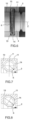
- FIG. 7 represents a sectional view perpendicular to the Z axis at the level of the grooves 13 of the assembly device 10 in symmetrical design according to the invention, the waveguides 1, 2 assembled.
- Y be a second axis perpendicular to the first axis Z and crossing the grooves 13 and 6.
- the coil of the inclined coil spring is circular.
- the associated grooves 13, 6 of the sheath and the waveguide 2 are symmetrical with respect to the second axis Y. In this symmetrical configuration, the insertion force to be applied for assembly is equal to the extraction force to be applied to disassemble the waveguides.
- FIG 8 represents a sectional view perpendicular to the Z axis at the level of the grooves of the assembly device in asymmetrical design according to the invention, the assembled waveguides.
- the turn of the spring with inclined turns is elliptical.
- the associated grooves 13, 6 of the sheath and the waveguide 2 are asymmetrical with respect to the second axis Y.
- the insertion force to be applied for the assembly is different from the extraction force to be applied to disassemble the waveguides.
- the extraction force is greater than the insertion force.
- a pressure of one waveguide on the other is previously defined.
- the spring with inclined turns is produced with previously defined parameters to meet the desired pressure requirement: degree of inclination of the turns, diameter of the turns, shape and dimensions of the section of the turns.
- the grooves in the ends of the waveguides and the sheath are designed to receive the spring.
- the pressure between the two waveguides is applied through the springs applying their force through the dimensioned grooves.
- the insertion and extraction forces can go up to 250 N depending on the design of the grooves and springs.
- the sheath 11 can be made of any material for common use.
- the sheath 11 is metallic, preferably aluminum.
- the waveguides are subjected to high temperature gradients, for example between -180°C and +180°C.
- the expansion of the materials is better controlled.
- the springs can be made of stainless steel with a silver-plating surface treatment. In addition to the uniform contact pressure that they provide at the periphery of elements 1, 2, the springs give very good results in EMC. Copper springs can also be used.
- the reversibly deformable elements 14 ensure the role of blocking the translation of the waveguides 1, 2 along the first axis Z.
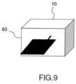
- FIG. 9 represents a satellite 60 equipped with at least one assembly 20 according to the invention.
Landscapes
- Engineering & Computer Science (AREA)
- Remote Sensing (AREA)
- Aviation & Aerospace Engineering (AREA)
- Physics & Mathematics (AREA)
- Astronomy & Astrophysics (AREA)
- General Physics & Mathematics (AREA)
- Waveguides (AREA)
Claims (6)
- Anordnung (20), umfassend einen ersten Hohlwellenleiter (1) und einen zweiten Hohlwellenleiter (2), die sich in Längsrichtung entlang einer ersten Achse (Z) erstrecken und jeweils ein Ende (3, 4) aufweisen, wobei die beiden Enden (3, 4) entlang der ersten Achse (Z) aneinandergrenzen, und eine Vorrichtung zum Zusammenbau (10) des ersten Wellenleiters (1) und des zweiten Wellenleiters (2),
wobei die Vorrichtung zum Zusammenbau (10) Folgendes umfasst:- eine erste ringförmige Nut (5) auf dem ersten Hohlwellenleiter (1) und eine erste ringförmige Nut (6) an dem zweiten Hohlwellenleiter (2),- eine Hülse (11), welche die Enden (3, 4) des ersten und zweiten Hohlwellenleiters (1, 2) umgibt, wobei die Hülse (11) eine Innenwand (12) aufweist, die zwei erste ringförmige Nuten (13) umfasst, die den ersten ringförmigen Nuten (5, 6) des ersten und des zweiten Hohlwellenleiters (1, 2) zugewandt sind,- zwei reversibel verformbare Elemente (14), wobei ein erstes der beiden reversibel verformbaren Elemente (14) in einer ersten der beiden ersten Ringnuten (13) der Hülse (11) positioniert ist und in der ersten Ringnut (5) an dem ersten Hohlwellenleiter (1) positioniert ist, und ein zweites der beiden reversibel verformbaren Elemente (14) in einer zweiten der beiden ersten Ringnuten (13) der Hülse (11) positioniert ist und in der ersten Ringnut (6) an dem zweiten Hohlwellenleiter (2) positioniert ist, so dass der erste und der zweite Hohlwellenleiter (1, 2) gegen Verschiebung entlang der ersten Achse (Z) blockiert werden. - Anordnung (20) nach Anspruch 1, dadurch gekennzeichnet, dass die Enden (3, 4) des ersten und des zweiten Hohlwellenleiters (1, 2) einen elliptischen Querschnitt aufweisen.
- Anordnung (20) nach Anspruch 1 oder 2, dadurch gekennzeichnet, dass die Enden (3, 4) des ersten und des zweiten Hohlwellenleiters (1, 2) einen kreisförmigen Querschnitt aufweisen.
- Anordnung (20) nach einem der Ansprüche 2 oder 3, dadurch gekennzeichnet, dass das mindestens eine reversibel verformbare Element (14) eine Feder mit schrägen Windungen ist, so dass ein vordefinierter Druck zwischen dem ersten und dem zweiten Hohlwellenleiter (1, 2) untereinander ausgeübt wird.
- Anordnung (20) nach einem der vorhergehenden Ansprüche, wobei mindestens eines der beiden Enden (3, 4) zusätzlich mindestens eine zweite Ringnut (7, 8) umfasst, dadurch gekennzeichnet, dass die Innenwand (12) der Hülse (11) mindestens eine zweite Ringnut umfasst, die gegenüber der mindestens einen zweiten Ringnut (7, 8) der mindestens einen der beiden Enden (3, 4) angeordnet ist, und mindestens ein zweites reversibel verformbares Element, das in der mindestens einen zweiten Ringnut der Hülse (11) positioniert ist und in der mindestens einen zweiten Ringnut (7, 8) der mindestens einen der beiden Enden (3, 4) positioniert ist.
- Satellit (60), umfassend mindestens eine Anordnung (20) nach einem der vorhergehenden Ansprüche.
Applications Claiming Priority (1)
| Application Number | Priority Date | Filing Date | Title |
|---|---|---|---|
| FR1906651A FR3097691B1 (fr) | 2019-06-20 | 2019-06-20 | Dispositif d'assemblage de deux guides d'ondes |
Publications (3)
| Publication Number | Publication Date |
|---|---|
| EP3754779A1 EP3754779A1 (de) | 2020-12-23 |
| EP3754779C0 EP3754779C0 (de) | 2023-09-13 |
| EP3754779B1 true EP3754779B1 (de) | 2023-09-13 |
Family
ID=68654593
Family Applications (1)
| Application Number | Title | Priority Date | Filing Date |
|---|---|---|---|
| EP20178255.4A Active EP3754779B1 (de) | 2019-06-20 | 2020-06-04 | Vorrichtung zum zusammenbau von zwei wellenleitern |
Country Status (5)
| Country | Link |
|---|---|
| US (1) | US11258147B2 (de) |
| EP (1) | EP3754779B1 (de) |
| CA (1) | CA3084223A1 (de) |
| ES (1) | ES2963512T3 (de) |
| FR (1) | FR3097691B1 (de) |
Families Citing this family (3)
| Publication number | Priority date | Publication date | Assignee | Title |
|---|---|---|---|---|
| GB201912962D0 (en) * | 2019-09-09 | 2019-10-23 | Q Flo Ltd | Electromagnetic waveguide |
| CN115489766B (zh) * | 2022-08-31 | 2025-03-25 | 西安空间无线电技术研究所 | 一种卫星穿舱波导的连接结构 |
| DE102023201770A1 (de) * | 2023-02-27 | 2024-08-29 | Vega Grieshaber Kg | Füllstandmessgerät zum Einsatz in Hochdruckanwendungen |
Citations (1)
| Publication number | Priority date | Publication date | Assignee | Title |
|---|---|---|---|---|
| US3575675A (en) * | 1968-10-31 | 1971-04-20 | Telefunken Patent | Waveguide connector |
Family Cites Families (7)
| Publication number | Priority date | Publication date | Assignee | Title |
|---|---|---|---|---|
| US5082390A (en) * | 1991-01-22 | 1992-01-21 | Peter J. Balsells | Latching, holding and locking spring apparatus |
| US5926943A (en) * | 1997-02-14 | 1999-07-27 | Southeastern Univ. Research Assn. | Braid shielded RF bellows |
| US8167285B2 (en) | 2003-06-04 | 2012-05-01 | Bal Seal Engineering Co., Inc. | Spring latching connectors radially and axially mounted |
| US9267526B2 (en) | 2003-06-04 | 2016-02-23 | Bal Seal Engineering, Inc. | Spring latching connectors |
| JP2011507162A (ja) * | 2007-12-06 | 2011-03-03 | バル・シール・エンジニアリング | インラインコネクタ |
| WO2017137737A1 (en) * | 2016-02-10 | 2017-08-17 | Bae Systems Plc | Waveguides |
| US9948044B2 (en) * | 2016-09-12 | 2018-04-17 | Faraday & Future Inc. | Electrical and mechanical connector |
-
2019
- 2019-06-20 FR FR1906651A patent/FR3097691B1/fr active Active
-
2020
- 2020-06-04 ES ES20178255T patent/ES2963512T3/es active Active
- 2020-06-04 EP EP20178255.4A patent/EP3754779B1/de active Active
- 2020-06-17 US US16/904,542 patent/US11258147B2/en active Active
- 2020-06-18 CA CA3084223A patent/CA3084223A1/en active Pending
Patent Citations (1)
| Publication number | Priority date | Publication date | Assignee | Title |
|---|---|---|---|---|
| US3575675A (en) * | 1968-10-31 | 1971-04-20 | Telefunken Patent | Waveguide connector |
Also Published As
| Publication number | Publication date |
|---|---|
| EP3754779C0 (de) | 2023-09-13 |
| US11258147B2 (en) | 2022-02-22 |
| US20200403288A1 (en) | 2020-12-24 |
| FR3097691A1 (fr) | 2020-12-25 |
| FR3097691B1 (fr) | 2023-03-03 |
| ES2963512T3 (es) | 2024-03-27 |
| EP3754779A1 (de) | 2020-12-23 |
| CA3084223A1 (en) | 2020-12-20 |
Similar Documents
| Publication | Publication Date | Title |
|---|---|---|
| EP3754779B1 (de) | Vorrichtung zum zusammenbau von zwei wellenleitern | |
| EP3171451B1 (de) | Räumlicher leistungskombinator | |
| EP3027511B1 (de) | Verfahren und vorrichtung zum verbinden und trennen von zwei elementen mittels verbindungsplatten | |
| EP2448814A1 (de) | Rumpfelement mit einem rumpfsegment und übergangsvorrichtung | |
| EP3027510B1 (de) | Verfahren und vorrichtung zum linearen verbinden und trennen von zwei elementen mit versetzten energetischen mitteln | |
| EP3179551B1 (de) | Kompakteinheit zur doppelpolarisierten ansteuerung für ein strahlungselement einer antenne, und kompaktes netz, das mindestens vier kompakte ansteuerungseinheiten umfasst | |
| EP2909906B1 (de) | Elektrische vorrichtung mit leiterträger zwischen zwei kapselungsteilen | |
| FR2818239A1 (fr) | Structure d'assemblage sur un vehicule spatial | |
| FR2760294A1 (fr) | Colonnette d'accord micro-ondes rf a soufflet | |
| EP0687884A1 (de) | Hülle gegen Durchbiegung | |
| WO2002054128A1 (fr) | Procede et dispositif de fixation mecanique d'un composant optique | |
| CA2994641A1 (fr) | Satellite artificiel | |
| FR2978306A1 (fr) | Insert a pointes et dispositif mettant en oeuvre l'insert | |
| EP1705389B1 (de) | Montagevorrichtung mit pyrotechnischem Sprengbruchmittel | |
| FR2759158A1 (fr) | Charge generatrice de noyau comportant des moyens de liaison du revetement et de l'enveloppe | |
| EP4420194B1 (de) | Aktive antenne, insbesondere für den weltraumtechnikbereich | |
| EP0773424A1 (de) | Hohlladungsgefechtskopf mit verbesserter Beschleunigungsfestigkeit | |
| EP0803699A1 (de) | Vorrichtung zur Befestigung eines Kastens an einer Struktur | |
| EP3624255B1 (de) | Gruppe von hohleitern und antenne mit solcher gruppe | |
| EP0508884B1 (de) | Verbinder für optische Faserkabel | |
| FR2741144A1 (fr) | Charge formee comportant des moyens de maintien du revetement | |
| FR3079074A1 (fr) | Systeme d'assemblage sans vis de deux portions de guide d'onde creux | |
| CH508967A (fr) | Procédé de fabrication d'une enceinte étanche | |
| FR3145842A1 (fr) | Interface de fixation d’un faisceau de câbles électriques monté dans un tube configurée pour assurer l’interface entre ledit tube et un organe de fixation de tubes | |
| EP1234117A1 (de) | Mechanismus zur stossdämpfung, insbesondere zur verwendung im weltraum |
Legal Events
| Date | Code | Title | Description |
|---|---|---|---|
| PUAI | Public reference made under article 153(3) epc to a published international application that has entered the european phase |
Free format text: ORIGINAL CODE: 0009012 |
|
| STAA | Information on the status of an ep patent application or granted ep patent |
Free format text: STATUS: THE APPLICATION HAS BEEN PUBLISHED |
|
| AK | Designated contracting states |
Kind code of ref document: A1 Designated state(s): AL AT BE BG CH CY CZ DE DK EE ES FI FR GB GR HR HU IE IS IT LI LT LU LV MC MK MT NL NO PL PT RO RS SE SI SK SM TR |
|
| AX | Request for extension of the european patent |
Extension state: BA ME |
|
| STAA | Information on the status of an ep patent application or granted ep patent |
Free format text: STATUS: REQUEST FOR EXAMINATION WAS MADE |
|
| 17P | Request for examination filed |
Effective date: 20210611 |
|
| RBV | Designated contracting states (corrected) |
Designated state(s): AL AT BE BG CH CY CZ DE DK EE ES FI FR GB GR HR HU IE IS IT LI LT LU LV MC MK MT NL NO PL PT RO RS SE SI SK SM TR |
|
| REG | Reference to a national code |
Ref country code: DE Ref legal event code: R079 Free format text: PREVIOUS MAIN CLASS: H01P0001060000 Ipc: H01P0001040000 Ref country code: DE Ref legal event code: R079 Ref document number: 602020017511 Country of ref document: DE Free format text: PREVIOUS MAIN CLASS: H01P0001060000 Ipc: H01P0001040000 |
|
| GRAP | Despatch of communication of intention to grant a patent |
Free format text: ORIGINAL CODE: EPIDOSNIGR1 |
|
| STAA | Information on the status of an ep patent application or granted ep patent |
Free format text: STATUS: GRANT OF PATENT IS INTENDED |
|
| RIC1 | Information provided on ipc code assigned before grant |
Ipc: H01P 1/04 20060101AFI20230320BHEP |
|
| INTG | Intention to grant announced |
Effective date: 20230412 |
|
| GRAS | Grant fee paid |
Free format text: ORIGINAL CODE: EPIDOSNIGR3 |
|
| GRAA | (expected) grant |
Free format text: ORIGINAL CODE: 0009210 |
|
| STAA | Information on the status of an ep patent application or granted ep patent |
Free format text: STATUS: THE PATENT HAS BEEN GRANTED |
|
| AK | Designated contracting states |
Kind code of ref document: B1 Designated state(s): AL AT BE BG CH CY CZ DE DK EE ES FI FR GB GR HR HU IE IS IT LI LT LU LV MC MK MT NL NO PL PT RO RS SE SI SK SM TR |
|
| REG | Reference to a national code |
Ref country code: CH Ref legal event code: EP |
|
| REG | Reference to a national code |
Ref country code: DE Ref legal event code: R096 Ref document number: 602020017511 Country of ref document: DE |
|
| REG | Reference to a national code |
Ref country code: IE Ref legal event code: FG4D Free format text: LANGUAGE OF EP DOCUMENT: FRENCH |
|
| U01 | Request for unitary effect filed |
Effective date: 20231005 |
|
| U07 | Unitary effect registered |
Designated state(s): AT BE BG DE DK EE FI FR IT LT LU LV MT NL PT SE SI Effective date: 20231016 |
|
| PG25 | Lapsed in a contracting state [announced via postgrant information from national office to epo] |
Ref country code: GR Free format text: LAPSE BECAUSE OF FAILURE TO SUBMIT A TRANSLATION OF THE DESCRIPTION OR TO PAY THE FEE WITHIN THE PRESCRIBED TIME-LIMIT Effective date: 20231214 |
|
| PG25 | Lapsed in a contracting state [announced via postgrant information from national office to epo] |
Ref country code: RS Free format text: LAPSE BECAUSE OF FAILURE TO SUBMIT A TRANSLATION OF THE DESCRIPTION OR TO PAY THE FEE WITHIN THE PRESCRIBED TIME-LIMIT Effective date: 20230913 Ref country code: NO Free format text: LAPSE BECAUSE OF FAILURE TO SUBMIT A TRANSLATION OF THE DESCRIPTION OR TO PAY THE FEE WITHIN THE PRESCRIBED TIME-LIMIT Effective date: 20231213 Ref country code: HR Free format text: LAPSE BECAUSE OF FAILURE TO SUBMIT A TRANSLATION OF THE DESCRIPTION OR TO PAY THE FEE WITHIN THE PRESCRIBED TIME-LIMIT Effective date: 20230913 Ref country code: GR Free format text: LAPSE BECAUSE OF FAILURE TO SUBMIT A TRANSLATION OF THE DESCRIPTION OR TO PAY THE FEE WITHIN THE PRESCRIBED TIME-LIMIT Effective date: 20231214 |
|
| REG | Reference to a national code |
Ref country code: ES Ref legal event code: FG2A Ref document number: 2963512 Country of ref document: ES Kind code of ref document: T3 Effective date: 20240327 |
|
| PG25 | Lapsed in a contracting state [announced via postgrant information from national office to epo] |
Ref country code: IS Free format text: LAPSE BECAUSE OF FAILURE TO SUBMIT A TRANSLATION OF THE DESCRIPTION OR TO PAY THE FEE WITHIN THE PRESCRIBED TIME-LIMIT Effective date: 20240113 |
|
| PG25 | Lapsed in a contracting state [announced via postgrant information from national office to epo] |
Ref country code: SM Free format text: LAPSE BECAUSE OF FAILURE TO SUBMIT A TRANSLATION OF THE DESCRIPTION OR TO PAY THE FEE WITHIN THE PRESCRIBED TIME-LIMIT Effective date: 20230913 Ref country code: RO Free format text: LAPSE BECAUSE OF FAILURE TO SUBMIT A TRANSLATION OF THE DESCRIPTION OR TO PAY THE FEE WITHIN THE PRESCRIBED TIME-LIMIT Effective date: 20230913 Ref country code: IS Free format text: LAPSE BECAUSE OF FAILURE TO SUBMIT A TRANSLATION OF THE DESCRIPTION OR TO PAY THE FEE WITHIN THE PRESCRIBED TIME-LIMIT Effective date: 20240113 Ref country code: CZ Free format text: LAPSE BECAUSE OF FAILURE TO SUBMIT A TRANSLATION OF THE DESCRIPTION OR TO PAY THE FEE WITHIN THE PRESCRIBED TIME-LIMIT Effective date: 20230913 Ref country code: SK Free format text: LAPSE BECAUSE OF FAILURE TO SUBMIT A TRANSLATION OF THE DESCRIPTION OR TO PAY THE FEE WITHIN THE PRESCRIBED TIME-LIMIT Effective date: 20230913 |
|
| PG25 | Lapsed in a contracting state [announced via postgrant information from national office to epo] |
Ref country code: PL Free format text: LAPSE BECAUSE OF FAILURE TO SUBMIT A TRANSLATION OF THE DESCRIPTION OR TO PAY THE FEE WITHIN THE PRESCRIBED TIME-LIMIT Effective date: 20230913 |
|
| REG | Reference to a national code |
Ref country code: DE Ref legal event code: R097 Ref document number: 602020017511 Country of ref document: DE |
|
| U20 | Renewal fee for the european patent with unitary effect paid |
Year of fee payment: 5 Effective date: 20240522 |
|
| PLBE | No opposition filed within time limit |
Free format text: ORIGINAL CODE: 0009261 |
|
| STAA | Information on the status of an ep patent application or granted ep patent |
Free format text: STATUS: NO OPPOSITION FILED WITHIN TIME LIMIT |
|
| 26N | No opposition filed |
Effective date: 20240614 |
|
| PG25 | Lapsed in a contracting state [announced via postgrant information from national office to epo] |
Ref country code: MC Free format text: LAPSE BECAUSE OF FAILURE TO SUBMIT A TRANSLATION OF THE DESCRIPTION OR TO PAY THE FEE WITHIN THE PRESCRIBED TIME-LIMIT Effective date: 20230913 |
|
| REG | Reference to a national code |
Ref country code: CH Ref legal event code: PL |
|
| PG25 | Lapsed in a contracting state [announced via postgrant information from national office to epo] |
Ref country code: IE Free format text: LAPSE BECAUSE OF NON-PAYMENT OF DUE FEES Effective date: 20240604 |
|
| PG25 | Lapsed in a contracting state [announced via postgrant information from national office to epo] |
Ref country code: CH Free format text: LAPSE BECAUSE OF NON-PAYMENT OF DUE FEES Effective date: 20240630 |
|
| U20 | Renewal fee for the european patent with unitary effect paid |
Year of fee payment: 6 Effective date: 20250522 |
|
| PGFP | Annual fee paid to national office [announced via postgrant information from national office to epo] |
Ref country code: GB Payment date: 20250515 Year of fee payment: 6 |
|
| PGFP | Annual fee paid to national office [announced via postgrant information from national office to epo] |
Ref country code: ES Payment date: 20250707 Year of fee payment: 6 |
|
| PG25 | Lapsed in a contracting state [announced via postgrant information from national office to epo] |
Ref country code: CY Free format text: LAPSE BECAUSE OF FAILURE TO SUBMIT A TRANSLATION OF THE DESCRIPTION OR TO PAY THE FEE WITHIN THE PRESCRIBED TIME-LIMIT; INVALID AB INITIO Effective date: 20200604 |