EP3624255B1 - Gruppe von hohleitern und antenne mit solcher gruppe - Google Patents
Gruppe von hohleitern und antenne mit solcher gruppe Download PDFInfo
- Publication number
- EP3624255B1 EP3624255B1 EP19196917.9A EP19196917A EP3624255B1 EP 3624255 B1 EP3624255 B1 EP 3624255B1 EP 19196917 A EP19196917 A EP 19196917A EP 3624255 B1 EP3624255 B1 EP 3624255B1
- Authority
- EP
- European Patent Office
- Prior art keywords
- waveguide
- radio
- waveguides
- transmission channel
- rows
- Prior art date
- Legal status (The legal status is an assumption and is not a legal conclusion. Google has not performed a legal analysis and makes no representation as to the accuracy of the status listed.)
- Active
Links
- 230000005540 biological transmission Effects 0.000 claims description 24
- 239000000463 material Substances 0.000 description 4
- 229910052782 aluminium Inorganic materials 0.000 description 2
- XAGFODPZIPBFFR-UHFFFAOYSA-N aluminium Chemical compound [Al] XAGFODPZIPBFFR-UHFFFAOYSA-N 0.000 description 2
- OKTJSMMVPCPJKN-UHFFFAOYSA-N Carbon Chemical compound [C] OKTJSMMVPCPJKN-UHFFFAOYSA-N 0.000 description 1
- 230000004888 barrier function Effects 0.000 description 1
- 229910052799 carbon Inorganic materials 0.000 description 1
- 239000000919 ceramic Substances 0.000 description 1
- 239000004020 conductor Substances 0.000 description 1
- 230000001419 dependent effect Effects 0.000 description 1
- 238000003780 insertion Methods 0.000 description 1
- 230000037431 insertion Effects 0.000 description 1
- 238000004519 manufacturing process Methods 0.000 description 1
- 229910052751 metal Inorganic materials 0.000 description 1
- 239000002184 metal Substances 0.000 description 1
- 238000000034 method Methods 0.000 description 1
Images

Classifications
-
- H—ELECTRICITY
- H01—ELECTRIC ELEMENTS
- H01P—WAVEGUIDES; RESONATORS, LINES, OR OTHER DEVICES OF THE WAVEGUIDE TYPE
- H01P3/00—Waveguides; Transmission lines of the waveguide type
- H01P3/12—Hollow waveguides
- H01P3/121—Hollow waveguides integrated in a substrate
-
- H—ELECTRICITY
- H01—ELECTRIC ELEMENTS
- H01P—WAVEGUIDES; RESONATORS, LINES, OR OTHER DEVICES OF THE WAVEGUIDE TYPE
- H01P1/00—Auxiliary devices
- H01P1/06—Movable joints, e.g. rotating joints
- H01P1/061—Movable joints, e.g. rotating joints the relative movement being a translation along an axis common to at least two rectilinear parts, e.g. expansion joints
-
- G—PHYSICS
- G02—OPTICS
- G02B—OPTICAL ELEMENTS, SYSTEMS OR APPARATUS
- G02B6/00—Light guides; Structural details of arrangements comprising light guides and other optical elements, e.g. couplings
- G02B6/24—Coupling light guides
- G02B6/42—Coupling light guides with opto-electronic elements
- G02B6/4201—Packages, e.g. shape, construction, internal or external details
- G02B6/4287—Optical modules with tapping or launching means through the surface of the waveguide
- G02B6/4291—Optical modules with tapping or launching means through the surface of the waveguide by accessing the evanescent field of the light guide
-
- H—ELECTRICITY
- H01—ELECTRIC ELEMENTS
- H01P—WAVEGUIDES; RESONATORS, LINES, OR OTHER DEVICES OF THE WAVEGUIDE TYPE
- H01P1/00—Auxiliary devices
- H01P1/20—Frequency-selective devices, e.g. filters
- H01P1/207—Hollow waveguide filters
-
- H—ELECTRICITY
- H01—ELECTRIC ELEMENTS
- H01P—WAVEGUIDES; RESONATORS, LINES, OR OTHER DEVICES OF THE WAVEGUIDE TYPE
- H01P3/00—Waveguides; Transmission lines of the waveguide type
- H01P3/12—Hollow waveguides
- H01P3/123—Hollow waveguides with a complex or stepped cross-section, e.g. ridged or grooved waveguides
-
- H—ELECTRICITY
- H01—ELECTRIC ELEMENTS
- H01P—WAVEGUIDES; RESONATORS, LINES, OR OTHER DEVICES OF THE WAVEGUIDE TYPE
- H01P5/00—Coupling devices of the waveguide type
- H01P5/02—Coupling devices of the waveguide type with invariable factor of coupling
- H01P5/022—Transitions between lines of the same kind and shape, but with different dimensions
- H01P5/024—Transitions between lines of the same kind and shape, but with different dimensions between hollow waveguides
-
- H—ELECTRICITY
- H01—ELECTRIC ELEMENTS
- H01Q—ANTENNAS, i.e. RADIO AERIALS
- H01Q13/00—Waveguide horns or mouths; Slot antennas; Leaky-waveguide antennas; Equivalent structures causing radiation along the transmission path of a guided wave
- H01Q13/10—Resonant slot antennas
- H01Q13/18—Resonant slot antennas the slot being backed by, or formed in boundary wall of, a resonant cavity ; Open cavity antennas
-
- H—ELECTRICITY
- H01—ELECTRIC ELEMENTS
- H01Q—ANTENNAS, i.e. RADIO AERIALS
- H01Q21/00—Antenna arrays or systems
- H01Q21/0006—Particular feeding systems
- H01Q21/0037—Particular feeding systems linear waveguide fed arrays
- H01Q21/0043—Slotted waveguides
- H01Q21/005—Slotted waveguides arrays
-
- H—ELECTRICITY
- H01—ELECTRIC ELEMENTS
- H01Q—ANTENNAS, i.e. RADIO AERIALS
- H01Q21/00—Antenna arrays or systems
- H01Q21/0006—Particular feeding systems
- H01Q21/0037—Particular feeding systems linear waveguide fed arrays
- H01Q21/0043—Slotted waveguides
- H01Q21/0062—Slotted waveguides the slots being disposed around the feeding waveguide
-
- H—ELECTRICITY
- H01—ELECTRIC ELEMENTS
- H01Q—ANTENNAS, i.e. RADIO AERIALS
- H01Q3/00—Arrangements for changing or varying the orientation or the shape of the directional pattern of the waves radiated from an antenna or antenna system
- H01Q3/02—Arrangements for changing or varying the orientation or the shape of the directional pattern of the waves radiated from an antenna or antenna system using mechanical movement of antenna or antenna system as a whole
- H01Q3/04—Arrangements for changing or varying the orientation or the shape of the directional pattern of the waves radiated from an antenna or antenna system using mechanical movement of antenna or antenna system as a whole for varying one co-ordinate of the orientation
Definitions
- the present invention relates to a radio wave guiding assembly.
- the present invention also relates to an antenna comprising such an assembly.
- the invention proposes to solve the problems of difference in coefficients of thermal expansion in a system conducting radioelectric waves.
- the invention thus finds its interest particularly in the space field where considerable temperature variations generate strong thermal expansions. This is particularly the case of systems comprising waveguides, such as for example antennas on board satellites.
- temperature-stable materials such as, for example, carbon or ceramic.
- such a routing can degrade the radio performance of the system by insertion losses or ohmic losses. Furthermore, it can degrade the mechanical performance of the system by adding additional mass. He can also degrade the thermal performance of the system by adding additional energy to be dissipated following, in particular, ohmic losses.
- radio wave guidance systems as described in the documents US 2,850,706 A , US 2011/187614 A1 , US 2,588,103A , US 4,675,633A And US 2005/128028 A1 .
- the object of the present invention is to considerably simplify the routing of radioelectric waves in a system undergoing strong thermal variations and therefore to remedy the aforementioned problems.
- the subject of the invention is a guide assembly according to claim 1.
- the guide assembly comprises one or more of the features of the dependent claims.
- the present invention also relates to an antenna comprising such a radio wave guiding assembly.
- the antenna 10 of the figure 1 is for example an “Earth-facing” type antenna on board a satellite.
- such an antenna 10 comprises a reflector 12, a support 13 and an assembly 14 for transmitting/receiving radio waves.
- the reflector 12 is for example arranged on a surface 16 of the satellite oriented towards the terrestrial surface.
- the support 13 secures the transmission/reception assembly 14 to the satellite.
- This support 13 is made for example of a material whose dimensions are substantially invariable to temperature variations.
- the transmission/reception assembly 14 is arranged on the support 13 and comprises in particular a horn 21 for transmitting/receiving radio waves arranged facing the reflector 12, a radio exciter 22 connected to the horn 21 and a guide assembly 23 connecting the radio exciter 22 to a payload 25 of the satellite.
- Reflector 12 horn 21 and radio exciter 22 are known per se and will not be explained in detail below.
- the guide assembly 23 according to a first embodiment of the invention is illustrated in detail on the figure 2 And 3 .
- the guide assembly 23 forms a single radio wave transmission path.
- This transmission path makes it possible to transmit radio waves from the payload 25 of the satellite to the radio exciter 22 to be transmitted via the horn 21 or vice versa, radio waves received by the horn 21 and the radio exciter 22 to the load payload 25 from the satellite.
- the guide assembly 23 comprises a pair of waveguides 30 composed of a first waveguide 31 and a second waveguide 32, and a connecting piece 33 of these waveguides 31 , 32.
- the first waveguide 31 and the second waveguide 32 form successive sections of the same radio wave transmission path. They are for example made of metal such as aluminum and have for example the same cross-sectional shape. This shape corresponds for example to a rectangle.
- the first waveguide 31 is connected to the payload 25 of the satellite and the second waveguide is connected to the radio exciter 22.
- the first waveguide 31 and/or the second waveguide 32 can be connected to at least one other waveguide possibly via a connection part similar to the connection part 33.
- the first waveguide 31 forms part of the payload 25 of the satellite or of any final part onto which the corresponding transmission channel opens.
- the corresponding connection part connects the second waveguide to this payload or to this final part.
- the second waveguide 32 forms part of the radioelectric exciter 22 or of any other initial part from which the corresponding transmission path extends.
- the connecting part 33 is made for example of the same material as the waveguides 31, 32 and comprises two plates 35A, 35B arranged opposite each other, defining an internal space 36 between them. On the picture 2 , for reasons of simplicity, only plate 35A is visible.
- the connecting piece 33 further comprises limiting means 37 forming in the internal space 36 a transmission channel 40 of radio waves.
- the transmission channel 40 connects the two waveguides 31, 32 together. It therefore leads on the one hand to the first waveguide 31 and on the other hand to the second waveguide 32.
- At least one of the waveguides 31, 32 is inserted with a clearance into this channel 40 so that it can slide freely along the channel.
- the other waveguide that is to say the first waveguide 31 is integral with the connecting piece 33.
- the length of the channel 40 over which the second waveguide 32 can slide freely is chosen, for example, according to the maximum expansion of this guide in the direction of propagation of the waves.
- this length corresponds for example to the difference between the maximum length of this guide and its minimum length.
- the two waveguides 31, 32 are able to slide along the channel 40 with a clearance.
- the transmission channel 40 has for example a cross-sectional shape similar to that of the waveguides 31, 32 but of larger dimensions so that one or/and the other waveguide can slide freely along this channel 40.
- the transmission channel 40 is formed according to the technology known in English terminology under the name of “ groove gap waveguide ”.
- the delimitation means 37 are in the form of studs arranged on either side of the channel 40.
- these pads are arranged transversely relative to the plates 35A, 35B in at least two rows, each row corresponding to a radioelectric barrier then forming a "wall" of the channel 40.
- the studs are for example evenly spaced.
- the studs are arranged in at least two rows on each side of the channel 40. These rows extend for example in parallel directions and make it possible to limit the leakage of the radio waves passing through the channel 40. It is also possible to arrange the pads in at least three rows on each side of the channel 40 to have the necessary safety margin.
- the studs are integral with one of the plates 35A, 35B, for example with the plate 35A, and for example form a single piece made in one piece with this plate.
- the pads are spaced from the other plate by a predetermined distance.
- the spacing distance of the pads within each row, the spacing of the rows between them as well as the spacing of the pads of the plate 35B are chosen according to frequencies or/and lengths of the radio waves for which the path of corresponding transmission of the guide assembly 23 is designed. This choice is made according to techniques known per se.
- the antenna 10 undergoes considerable temperature variations.
- the various components of the guide assembly 23 expand.
- the first and the second waveguides 31, 32 expand by increasing their respective lengths.
- the second waveguide 32 slides along the transmission channel 40 towards the first waveguide 31 which makes it possible to “absorb” the dilated parts of these guides.
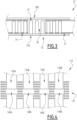
- FIG. 4 illustrates a guide assembly 123 according to a second embodiment of the invention.
- This guide assembly 123 can be mounted in the antenna 10 of the figure 1 instead of the guide assembly 23 described above.
- the guide assembly 123 according to the second embodiment differs from that according to the first embodiment only in that it comprises several pairs 130A to 130D of waveguides similar to the pair 30 of the first and second waveguides. waves 31, 32 described above and in that it comprises delimitation means 137 delimiting a transmission channel 140A to 140D for each pair 130A to 130D.
- the guide assembly 123 forms several radio wave transmission paths which are possibly designed to guide radio waves of different natures.
- the delimitation means 137 always take the form of pads arranged on either side of each transmission channel 140A to 140D.
- these transmission channels 140A to 140D are separated by pads arranged in three rows.
- the invention makes it possible to carry out the routing of the radioelectric waves in a very simple way, while taking into account the expansions of various components.
Landscapes
- Physics & Mathematics (AREA)
- General Physics & Mathematics (AREA)
- Optics & Photonics (AREA)
- Aerials With Secondary Devices (AREA)
- Waveguides (AREA)
- Details Of Aerials (AREA)
- Waveguide Aerials (AREA)
Claims (7)
- Leitanordnung (23; 123) von Funkwellen, umfassend ein Wellenleiterpaar (30; 130A, ..., 130D), das aus einem ersten Wellenleiter (31) und einem zweiten Wellenleiter (32) besteht, die aufeinanderfolgenden Abschnitte eines gleichen Übertragungswegs für Funkwellen bilden;die Anordnung (23; 123) ferner umfassend ein Anschlussstück (33), umfassend:- zwei Platten (35A, 35B), die einander gegenüberliegend angeordnet sind, wobei dazwischen ein Innenraum (36) definiert ist;- Begrenzungseinrichtungen (37; 137), die in dem Innenraum (36) einen Übertragungskanal (40; 140A,..., 140D) für Funkwellen begrenzen, wobei der Übertragungskanal (40; 140A,..., 140D) einerseits in den ersten Wellenleiter (31) und andererseits in den zweiten Wellenleiter (32) mündet;die Begrenzungseinrichtungen (37; 137) aus einer Vielzahl von Noppen gebildet sind, die sich quer zwischen den zwei Platten (35A, 35B) erstrecken;wobei der zweite Wellenleiter (32) geeignet ist, um mit einem Spiel frei entlang des Übertragungskanals (40; 140A,..., 140D) zu gleiten;wobei die Noppen in mindestens zwei Reihen angeordnet sind, wobei der Übertragungskanal (40; 140A,..., 140D) zwischen diesen Reihen gebildet ist.
- Anordnung (23; 123) nach Anspruch 1, dadurch gekennzeichnet, dass der erste Wellenleiter (31) einstückig mit dem Anschlussstück (33) ist.
- Anordnung (23; 123) nach einem der vorherigen Ansprüche, dadurch gekennzeichnet, dass jeder von dem ersten Wellenleiter (31) und dem zweiten Wellenleiter (32) zwischen den Reihen von Noppen eingefügt ist.
- Anordnung (23; 123) nach einem der vorherigen Ansprüche, dadurch gekennzeichnet, dass auf jeder Seite des Übertragungskanals (40; 140A, ..., 140D) die Noppen in mindestens zwei Reihen angeordnet sind, die sich entlang paralleler Richtungen erstrecken.
- Anordnung (23; 123) nach einem der vorherigen Ansprüche, dadurch gekennzeichnet, dass die Begrenzungseinrichtungen (37; 137) mit mindestens einer der Platten (35A, 35B) einstückig sind und von der anderen beabstandet sind.
- Anordnung (123) nach einem der vorherigen Ansprüche, dadurch gekennzeichnet, dass sie ferner ein weiteres Wellenleiterpaar (130A,...., 130D) analog zu dem Wellenleiterpaar aufweist und dass die Begrenzungseinrichtungen (137) in dem Innenraum (36) einen Übertragungskanal (40; 140A, ..., 140D) für jedes Wellenleiterpaar (130A, ..., 130D) begrenzen.
- Antenne (10), umfassend eine Leitanordnung (23; 123) für Funkwellen nach einem der vorherigen Ansprüche.
Applications Claiming Priority (1)
| Application Number | Priority Date | Filing Date | Title |
|---|---|---|---|
| FR1800955A FR3086104B1 (fr) | 2018-09-13 | 2018-09-13 | Ensemble de guidage d'ondes radioelectriques et antenne comprenant un tel ensemble |
Publications (3)
| Publication Number | Publication Date |
|---|---|
| EP3624255A1 EP3624255A1 (de) | 2020-03-18 |
| EP3624255B1 true EP3624255B1 (de) | 2023-08-09 |
| EP3624255C0 EP3624255C0 (de) | 2023-08-09 |
Family
ID=65200874
Family Applications (1)
| Application Number | Title | Priority Date | Filing Date |
|---|---|---|---|
| EP19196917.9A Active EP3624255B1 (de) | 2018-09-13 | 2019-09-12 | Gruppe von hohleitern und antenne mit solcher gruppe |
Country Status (4)
| Country | Link |
|---|---|
| US (1) | US11101534B2 (de) |
| EP (1) | EP3624255B1 (de) |
| ES (1) | ES2957313T3 (de) |
| FR (1) | FR3086104B1 (de) |
Families Citing this family (1)
| Publication number | Priority date | Publication date | Assignee | Title |
|---|---|---|---|---|
| CN114583426B (zh) * | 2022-03-15 | 2022-09-09 | 电子科技大学 | 一种h面剖分的太赫兹弯折波导结构 |
Citations (2)
| Publication number | Priority date | Publication date | Assignee | Title |
|---|---|---|---|---|
| US2850706A (en) * | 1955-05-31 | 1958-09-02 | William F Gabriel | Machined waveguide pin choke |
| US20110187614A1 (en) * | 2008-10-29 | 2011-08-04 | Hideki Kirino | High-frequency waveguide and phase shifter using same, radiator, electronic device which uses this phase shifter and radiator, antenna device, and electronic device equipped with same |
Family Cites Families (5)
| Publication number | Priority date | Publication date | Assignee | Title |
|---|---|---|---|---|
| US2588103A (en) * | 1946-09-14 | 1952-03-04 | Bell Telephone Labor Inc | Wave guide coupling between coaxial lines |
| FR2415885A1 (fr) * | 1978-01-27 | 1979-08-24 | Thomson Csf | Jonction pour guides d'ondes hyperfrequences, en particulier pour guides mobiles l'un par rapport a l'autre, et son application a la realisation d'une antenne telescopique |
| US4675633A (en) * | 1985-08-05 | 1987-06-23 | Harris Corporation | Waveguide expansion joint |
| EP1331688A1 (de) * | 2002-01-29 | 2003-07-30 | Era Patents Limited | Wellenleiter |
| JP5172481B2 (ja) * | 2008-06-05 | 2013-03-27 | 株式会社東芝 | ポスト壁導波路によるショートスロット方向性結合器とこれを用いたバトラーマトリクス及び車載レーダアンテナ |
-
2018
- 2018-09-13 FR FR1800955A patent/FR3086104B1/fr active Active
-
2019
- 2019-09-09 US US16/565,162 patent/US11101534B2/en active Active
- 2019-09-12 EP EP19196917.9A patent/EP3624255B1/de active Active
- 2019-09-12 ES ES19196917T patent/ES2957313T3/es active Active
Patent Citations (2)
| Publication number | Priority date | Publication date | Assignee | Title |
|---|---|---|---|---|
| US2850706A (en) * | 1955-05-31 | 1958-09-02 | William F Gabriel | Machined waveguide pin choke |
| US20110187614A1 (en) * | 2008-10-29 | 2011-08-04 | Hideki Kirino | High-frequency waveguide and phase shifter using same, radiator, electronic device which uses this phase shifter and radiator, antenna device, and electronic device equipped with same |
Also Published As
| Publication number | Publication date |
|---|---|
| FR3086104A1 (fr) | 2020-03-20 |
| ES2957313T3 (es) | 2024-01-17 |
| US11101534B2 (en) | 2021-08-24 |
| EP3624255A1 (de) | 2020-03-18 |
| US20200091576A1 (en) | 2020-03-19 |
| EP3624255C0 (de) | 2023-08-09 |
| FR3086104B1 (fr) | 2021-12-10 |
Similar Documents
| Publication | Publication Date | Title |
|---|---|---|
| EP3171451B1 (de) | Räumlicher leistungskombinator | |
| EP3057130B1 (de) | Rf-übertragungsvorrichtung mit integriertem reflektor von elektromagnetischen wellen | |
| EP3635229B1 (de) | Akustikplatte und zugehörige antriebseinheit | |
| EP3624255B1 (de) | Gruppe von hohleitern und antenne mit solcher gruppe | |
| WO2007006729A1 (fr) | Dispositif capacitif a volume capacitif optimise | |
| EP3136499A1 (de) | Aufteilungs-/kombinationssystem für hyperfrequenzwelle | |
| EP2447209B1 (de) | Mikroelektromechanisches System (MEMS) | |
| EP2658032B1 (de) | Hornstrahler einer Antenne mit gewelltem Gitter | |
| EP1798809A1 (de) | Vorrichtung zum Ausstrahlen und/oder Empfangen von elektromagnetischen Wellen für aerodynamisch gesteuerte Luftfahrzeuge | |
| EP1955100B1 (de) | Optisches instrument mit einer eingabevertiefung, in die ein spiegel eingelassen ist | |
| EP0063063B1 (de) | Mikrowellenantenne mit einem Spiegel und einem Tragkörper und Verbindungselement zwischen Spiegel und Tragkörper | |
| EP3052909B1 (de) | Flexible bestückte leiterplatte mit geringer emissivität | |
| FR2820790A1 (fr) | Procede et dispositif de fixation mecanique d'un composant optique | |
| EP2887113B1 (de) | Wabenstruktur | |
| EP3071483B1 (de) | Satellitentragestruktur mit einer dämpfungsverbindungsvorrichtung | |
| EP2936537B1 (de) | Mikrowellengenerator mit oszillierender virtueller kathode und offenen reflektoren | |
| FR3007237A1 (fr) | Circuit imprime a structure multicouche a faibles pertes dielectriques et refroidi | |
| FR3060867A1 (fr) | Architecture de bloc sources deployable, antenne compacte et satellite comportant une telle architecture | |
| EP3900104B1 (de) | Bidirektionaler hyperfrequenzkoppler mit zwei parallelen doppelrippenwellenleitern | |
| EP0466579A1 (de) | Doppelreflektor mit Gitter | |
| EP3416238A1 (de) | Sende- und empfangsanordnung für eine mehrfachstrahlantenne, und mehrfachstrahlantenne | |
| EP1279844B1 (de) | Drehbare Führungsvorrichtung für eine Last | |
| FR2820789A1 (fr) | Procede et dispositif de fixation mecanique d'un composant optique | |
| FR2854279A1 (fr) | Dispositif a cavite resonnante a conversion de variation dimensionnelle transversale, induite par une variation de temperature, en variation dimensionnelle longitudinale | |
| EP1066741A1 (de) | Elektronische schaltungsstruktur mit optimisierung des platzbedarfs in abhangigkeit vom vorhandenen volumen |
Legal Events
| Date | Code | Title | Description |
|---|---|---|---|
| PUAI | Public reference made under article 153(3) epc to a published international application that has entered the european phase |
Free format text: ORIGINAL CODE: 0009012 |
|
| STAA | Information on the status of an ep patent application or granted ep patent |
Free format text: STATUS: THE APPLICATION HAS BEEN PUBLISHED |
|
| STAA | Information on the status of an ep patent application or granted ep patent |
Free format text: STATUS: REQUEST FOR EXAMINATION WAS MADE |
|
| AK | Designated contracting states |
Kind code of ref document: A1 Designated state(s): AL AT BE BG CH CY CZ DE DK EE ES FI FR GB GR HR HU IE IS IT LI LT LU LV MC MK MT NL NO PL PT RO RS SE SI SK SM TR |
|
| AX | Request for extension of the european patent |
Extension state: BA ME |
|
| 17P | Request for examination filed |
Effective date: 20200302 |
|
| RBV | Designated contracting states (corrected) |
Designated state(s): AL AT BE BG CH CY CZ DE DK EE ES FI FR GB GR HR HU IE IS IT LI LT LU LV MC MK MT NL NO PL PT RO RS SE SI SK SM TR |
|
| STAA | Information on the status of an ep patent application or granted ep patent |
Free format text: STATUS: EXAMINATION IS IN PROGRESS |
|
| 17Q | First examination report despatched |
Effective date: 20210430 |
|
| GRAP | Despatch of communication of intention to grant a patent |
Free format text: ORIGINAL CODE: EPIDOSNIGR1 |
|
| STAA | Information on the status of an ep patent application or granted ep patent |
Free format text: STATUS: GRANT OF PATENT IS INTENDED |
|
| INTG | Intention to grant announced |
Effective date: 20221109 |
|
| GRAJ | Information related to disapproval of communication of intention to grant by the applicant or resumption of examination proceedings by the epo deleted |
Free format text: ORIGINAL CODE: EPIDOSDIGR1 |
|
| STAA | Information on the status of an ep patent application or granted ep patent |
Free format text: STATUS: EXAMINATION IS IN PROGRESS |
|
| GRAP | Despatch of communication of intention to grant a patent |
Free format text: ORIGINAL CODE: EPIDOSNIGR1 |
|
| STAA | Information on the status of an ep patent application or granted ep patent |
Free format text: STATUS: GRANT OF PATENT IS INTENDED |
|
| INTC | Intention to grant announced (deleted) | ||
| INTG | Intention to grant announced |
Effective date: 20230327 |
|
| GRAS | Grant fee paid |
Free format text: ORIGINAL CODE: EPIDOSNIGR3 |
|
| GRAA | (expected) grant |
Free format text: ORIGINAL CODE: 0009210 |
|
| STAA | Information on the status of an ep patent application or granted ep patent |
Free format text: STATUS: THE PATENT HAS BEEN GRANTED |
|
| AK | Designated contracting states |
Kind code of ref document: B1 Designated state(s): AL AT BE BG CH CY CZ DE DK EE ES FI FR GB GR HR HU IE IS IT LI LT LU LV MC MK MT NL NO PL PT RO RS SE SI SK SM TR |
|
| REG | Reference to a national code |
Ref country code: GB Ref legal event code: FG4D Free format text: NOT ENGLISH |
|
| REG | Reference to a national code |
Ref country code: CH Ref legal event code: EP |
|
| REG | Reference to a national code |
Ref country code: IE Ref legal event code: FG4D Free format text: LANGUAGE OF EP DOCUMENT: FRENCH |
|
| REG | Reference to a national code |
Ref country code: DE Ref legal event code: R096 Ref document number: 602019034433 Country of ref document: DE |
|
| U01 | Request for unitary effect filed |
Effective date: 20230810 |
|
| U07 | Unitary effect registered |
Designated state(s): AT BE BG DE DK EE FI FR IT LT LU LV MT NL PT SE SI Effective date: 20230817 |
|
| PGFP | Annual fee paid to national office [announced via postgrant information from national office to epo] |
Ref country code: GB Payment date: 20230920 Year of fee payment: 5 |
|
| U20 | Renewal fee paid [unitary effect] |
Year of fee payment: 5 Effective date: 20230926 |
|
| REG | Reference to a national code |
Ref country code: ES Ref legal event code: FG2A Ref document number: 2957313 Country of ref document: ES Kind code of ref document: T3 Effective date: 20240117 |
|
| PG25 | Lapsed in a contracting state [announced via postgrant information from national office to epo] |
Ref country code: GR Free format text: LAPSE BECAUSE OF FAILURE TO SUBMIT A TRANSLATION OF THE DESCRIPTION OR TO PAY THE FEE WITHIN THE PRESCRIBED TIME-LIMIT Effective date: 20231110 |
|
| PGFP | Annual fee paid to national office [announced via postgrant information from national office to epo] |
Ref country code: ES Payment date: 20231006 Year of fee payment: 5 |
|
| PG25 | Lapsed in a contracting state [announced via postgrant information from national office to epo] |
Ref country code: IS Free format text: LAPSE BECAUSE OF FAILURE TO SUBMIT A TRANSLATION OF THE DESCRIPTION OR TO PAY THE FEE WITHIN THE PRESCRIBED TIME-LIMIT Effective date: 20231209 |
|
| PG25 | Lapsed in a contracting state [announced via postgrant information from national office to epo] |
Ref country code: RS Free format text: LAPSE BECAUSE OF FAILURE TO SUBMIT A TRANSLATION OF THE DESCRIPTION OR TO PAY THE FEE WITHIN THE PRESCRIBED TIME-LIMIT Effective date: 20230809 Ref country code: NO Free format text: LAPSE BECAUSE OF FAILURE TO SUBMIT A TRANSLATION OF THE DESCRIPTION OR TO PAY THE FEE WITHIN THE PRESCRIBED TIME-LIMIT Effective date: 20231109 Ref country code: IS Free format text: LAPSE BECAUSE OF FAILURE TO SUBMIT A TRANSLATION OF THE DESCRIPTION OR TO PAY THE FEE WITHIN THE PRESCRIBED TIME-LIMIT Effective date: 20231209 Ref country code: HR Free format text: LAPSE BECAUSE OF FAILURE TO SUBMIT A TRANSLATION OF THE DESCRIPTION OR TO PAY THE FEE WITHIN THE PRESCRIBED TIME-LIMIT Effective date: 20230809 Ref country code: GR Free format text: LAPSE BECAUSE OF FAILURE TO SUBMIT A TRANSLATION OF THE DESCRIPTION OR TO PAY THE FEE WITHIN THE PRESCRIBED TIME-LIMIT Effective date: 20231110 |
|
| PG25 | Lapsed in a contracting state [announced via postgrant information from national office to epo] |
Ref country code: PL Free format text: LAPSE BECAUSE OF FAILURE TO SUBMIT A TRANSLATION OF THE DESCRIPTION OR TO PAY THE FEE WITHIN THE PRESCRIBED TIME-LIMIT Effective date: 20230809 |
|
| PG25 | Lapsed in a contracting state [announced via postgrant information from national office to epo] |
Ref country code: SM Free format text: LAPSE BECAUSE OF FAILURE TO SUBMIT A TRANSLATION OF THE DESCRIPTION OR TO PAY THE FEE WITHIN THE PRESCRIBED TIME-LIMIT Effective date: 20230809 Ref country code: RO Free format text: LAPSE BECAUSE OF FAILURE TO SUBMIT A TRANSLATION OF THE DESCRIPTION OR TO PAY THE FEE WITHIN THE PRESCRIBED TIME-LIMIT Effective date: 20230809 Ref country code: CZ Free format text: LAPSE BECAUSE OF FAILURE TO SUBMIT A TRANSLATION OF THE DESCRIPTION OR TO PAY THE FEE WITHIN THE PRESCRIBED TIME-LIMIT Effective date: 20230809 Ref country code: SK Free format text: LAPSE BECAUSE OF FAILURE TO SUBMIT A TRANSLATION OF THE DESCRIPTION OR TO PAY THE FEE WITHIN THE PRESCRIBED TIME-LIMIT Effective date: 20230809 |
|
| REG | Reference to a national code |
Ref country code: CH Ref legal event code: PL |