EP3624255B1 - Guiding set of radio-electric waves and antenna comprising such a set - Google Patents
Guiding set of radio-electric waves and antenna comprising such a set Download PDFInfo
- Publication number
- EP3624255B1 EP3624255B1 EP19196917.9A EP19196917A EP3624255B1 EP 3624255 B1 EP3624255 B1 EP 3624255B1 EP 19196917 A EP19196917 A EP 19196917A EP 3624255 B1 EP3624255 B1 EP 3624255B1
- Authority
- EP
- European Patent Office
- Prior art keywords
- waveguide
- radio
- waveguides
- transmission channel
- rows
- Prior art date
- Legal status (The legal status is an assumption and is not a legal conclusion. Google has not performed a legal analysis and makes no representation as to the accuracy of the status listed.)
- Active
Links
- 230000005540 biological transmission Effects 0.000 claims description 24
- 239000000463 material Substances 0.000 description 4
- 229910052782 aluminium Inorganic materials 0.000 description 2
- XAGFODPZIPBFFR-UHFFFAOYSA-N aluminium Chemical compound [Al] XAGFODPZIPBFFR-UHFFFAOYSA-N 0.000 description 2
- OKTJSMMVPCPJKN-UHFFFAOYSA-N Carbon Chemical compound [C] OKTJSMMVPCPJKN-UHFFFAOYSA-N 0.000 description 1
- 230000004888 barrier function Effects 0.000 description 1
- 229910052799 carbon Inorganic materials 0.000 description 1
- 239000000919 ceramic Substances 0.000 description 1
- 239000004020 conductor Substances 0.000 description 1
- 230000001419 dependent effect Effects 0.000 description 1
- 238000003780 insertion Methods 0.000 description 1
- 230000037431 insertion Effects 0.000 description 1
- 238000004519 manufacturing process Methods 0.000 description 1
- 229910052751 metal Inorganic materials 0.000 description 1
- 239000002184 metal Substances 0.000 description 1
- 238000000034 method Methods 0.000 description 1
Images

Classifications
-
- H—ELECTRICITY
- H01—ELECTRIC ELEMENTS
- H01P—WAVEGUIDES; RESONATORS, LINES, OR OTHER DEVICES OF THE WAVEGUIDE TYPE
- H01P3/00—Waveguides; Transmission lines of the waveguide type
- H01P3/12—Hollow waveguides
- H01P3/121—Hollow waveguides integrated in a substrate
-
- H—ELECTRICITY
- H01—ELECTRIC ELEMENTS
- H01P—WAVEGUIDES; RESONATORS, LINES, OR OTHER DEVICES OF THE WAVEGUIDE TYPE
- H01P1/00—Auxiliary devices
- H01P1/06—Movable joints, e.g. rotating joints
- H01P1/061—Movable joints, e.g. rotating joints the relative movement being a translation along an axis common to at least two rectilinear parts, e.g. expansion joints
-
- G—PHYSICS
- G02—OPTICS
- G02B—OPTICAL ELEMENTS, SYSTEMS OR APPARATUS
- G02B6/00—Light guides; Structural details of arrangements comprising light guides and other optical elements, e.g. couplings
- G02B6/24—Coupling light guides
- G02B6/42—Coupling light guides with opto-electronic elements
- G02B6/4201—Packages, e.g. shape, construction, internal or external details
- G02B6/4287—Optical modules with tapping or launching means through the surface of the waveguide
- G02B6/4291—Optical modules with tapping or launching means through the surface of the waveguide by accessing the evanescent field of the light guide
-
- H—ELECTRICITY
- H01—ELECTRIC ELEMENTS
- H01P—WAVEGUIDES; RESONATORS, LINES, OR OTHER DEVICES OF THE WAVEGUIDE TYPE
- H01P1/00—Auxiliary devices
- H01P1/20—Frequency-selective devices, e.g. filters
- H01P1/207—Hollow waveguide filters
-
- H—ELECTRICITY
- H01—ELECTRIC ELEMENTS
- H01P—WAVEGUIDES; RESONATORS, LINES, OR OTHER DEVICES OF THE WAVEGUIDE TYPE
- H01P3/00—Waveguides; Transmission lines of the waveguide type
- H01P3/12—Hollow waveguides
- H01P3/123—Hollow waveguides with a complex or stepped cross-section, e.g. ridged or grooved waveguides
-
- H—ELECTRICITY
- H01—ELECTRIC ELEMENTS
- H01P—WAVEGUIDES; RESONATORS, LINES, OR OTHER DEVICES OF THE WAVEGUIDE TYPE
- H01P5/00—Coupling devices of the waveguide type
- H01P5/02—Coupling devices of the waveguide type with invariable factor of coupling
- H01P5/022—Transitions between lines of the same kind and shape, but with different dimensions
- H01P5/024—Transitions between lines of the same kind and shape, but with different dimensions between hollow waveguides
-
- H—ELECTRICITY
- H01—ELECTRIC ELEMENTS
- H01Q—ANTENNAS, i.e. RADIO AERIALS
- H01Q13/00—Waveguide horns or mouths; Slot antennas; Leaky-waveguide antennas; Equivalent structures causing radiation along the transmission path of a guided wave
- H01Q13/10—Resonant slot antennas
- H01Q13/18—Resonant slot antennas the slot being backed by, or formed in boundary wall of, a resonant cavity ; Open cavity antennas
-
- H—ELECTRICITY
- H01—ELECTRIC ELEMENTS
- H01Q—ANTENNAS, i.e. RADIO AERIALS
- H01Q21/00—Antenna arrays or systems
- H01Q21/0006—Particular feeding systems
- H01Q21/0037—Particular feeding systems linear waveguide fed arrays
- H01Q21/0043—Slotted waveguides
- H01Q21/005—Slotted waveguides arrays
-
- H—ELECTRICITY
- H01—ELECTRIC ELEMENTS
- H01Q—ANTENNAS, i.e. RADIO AERIALS
- H01Q21/00—Antenna arrays or systems
- H01Q21/0006—Particular feeding systems
- H01Q21/0037—Particular feeding systems linear waveguide fed arrays
- H01Q21/0043—Slotted waveguides
- H01Q21/0062—Slotted waveguides the slots being disposed around the feeding waveguide
-
- H—ELECTRICITY
- H01—ELECTRIC ELEMENTS
- H01Q—ANTENNAS, i.e. RADIO AERIALS
- H01Q3/00—Arrangements for changing or varying the orientation or the shape of the directional pattern of the waves radiated from an antenna or antenna system
- H01Q3/02—Arrangements for changing or varying the orientation or the shape of the directional pattern of the waves radiated from an antenna or antenna system using mechanical movement of antenna or antenna system as a whole
- H01Q3/04—Arrangements for changing or varying the orientation or the shape of the directional pattern of the waves radiated from an antenna or antenna system using mechanical movement of antenna or antenna system as a whole for varying one co-ordinate of the orientation
Definitions
- the present invention relates to a radio wave guiding assembly.
- the present invention also relates to an antenna comprising such an assembly.
- the invention proposes to solve the problems of difference in coefficients of thermal expansion in a system conducting radioelectric waves.
- the invention thus finds its interest particularly in the space field where considerable temperature variations generate strong thermal expansions. This is particularly the case of systems comprising waveguides, such as for example antennas on board satellites.
- temperature-stable materials such as, for example, carbon or ceramic.
- such a routing can degrade the radio performance of the system by insertion losses or ohmic losses. Furthermore, it can degrade the mechanical performance of the system by adding additional mass. He can also degrade the thermal performance of the system by adding additional energy to be dissipated following, in particular, ohmic losses.
- radio wave guidance systems as described in the documents US 2,850,706 A , US 2011/187614 A1 , US 2,588,103A , US 4,675,633A And US 2005/128028 A1 .
- the object of the present invention is to considerably simplify the routing of radioelectric waves in a system undergoing strong thermal variations and therefore to remedy the aforementioned problems.
- the subject of the invention is a guide assembly according to claim 1.
- the guide assembly comprises one or more of the features of the dependent claims.
- the present invention also relates to an antenna comprising such a radio wave guiding assembly.
- the antenna 10 of the figure 1 is for example an “Earth-facing” type antenna on board a satellite.
- such an antenna 10 comprises a reflector 12, a support 13 and an assembly 14 for transmitting/receiving radio waves.
- the reflector 12 is for example arranged on a surface 16 of the satellite oriented towards the terrestrial surface.
- the support 13 secures the transmission/reception assembly 14 to the satellite.
- This support 13 is made for example of a material whose dimensions are substantially invariable to temperature variations.
- the transmission/reception assembly 14 is arranged on the support 13 and comprises in particular a horn 21 for transmitting/receiving radio waves arranged facing the reflector 12, a radio exciter 22 connected to the horn 21 and a guide assembly 23 connecting the radio exciter 22 to a payload 25 of the satellite.
- Reflector 12 horn 21 and radio exciter 22 are known per se and will not be explained in detail below.
- the guide assembly 23 according to a first embodiment of the invention is illustrated in detail on the figure 2 And 3 .
- the guide assembly 23 forms a single radio wave transmission path.
- This transmission path makes it possible to transmit radio waves from the payload 25 of the satellite to the radio exciter 22 to be transmitted via the horn 21 or vice versa, radio waves received by the horn 21 and the radio exciter 22 to the load payload 25 from the satellite.
- the guide assembly 23 comprises a pair of waveguides 30 composed of a first waveguide 31 and a second waveguide 32, and a connecting piece 33 of these waveguides 31 , 32.
- the first waveguide 31 and the second waveguide 32 form successive sections of the same radio wave transmission path. They are for example made of metal such as aluminum and have for example the same cross-sectional shape. This shape corresponds for example to a rectangle.
- the first waveguide 31 is connected to the payload 25 of the satellite and the second waveguide is connected to the radio exciter 22.
- the first waveguide 31 and/or the second waveguide 32 can be connected to at least one other waveguide possibly via a connection part similar to the connection part 33.
- the first waveguide 31 forms part of the payload 25 of the satellite or of any final part onto which the corresponding transmission channel opens.
- the corresponding connection part connects the second waveguide to this payload or to this final part.
- the second waveguide 32 forms part of the radioelectric exciter 22 or of any other initial part from which the corresponding transmission path extends.
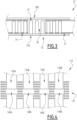
- the connecting part 33 is made for example of the same material as the waveguides 31, 32 and comprises two plates 35A, 35B arranged opposite each other, defining an internal space 36 between them. On the picture 2 , for reasons of simplicity, only plate 35A is visible.
- the connecting piece 33 further comprises limiting means 37 forming in the internal space 36 a transmission channel 40 of radio waves.
- the transmission channel 40 connects the two waveguides 31, 32 together. It therefore leads on the one hand to the first waveguide 31 and on the other hand to the second waveguide 32.
- At least one of the waveguides 31, 32 is inserted with a clearance into this channel 40 so that it can slide freely along the channel.
- the other waveguide that is to say the first waveguide 31 is integral with the connecting piece 33.
- the length of the channel 40 over which the second waveguide 32 can slide freely is chosen, for example, according to the maximum expansion of this guide in the direction of propagation of the waves.
- this length corresponds for example to the difference between the maximum length of this guide and its minimum length.
- the two waveguides 31, 32 are able to slide along the channel 40 with a clearance.
- the transmission channel 40 has for example a cross-sectional shape similar to that of the waveguides 31, 32 but of larger dimensions so that one or/and the other waveguide can slide freely along this channel 40.
- the transmission channel 40 is formed according to the technology known in English terminology under the name of “ groove gap waveguide ”.
- the delimitation means 37 are in the form of studs arranged on either side of the channel 40.
- these pads are arranged transversely relative to the plates 35A, 35B in at least two rows, each row corresponding to a radioelectric barrier then forming a "wall" of the channel 40.
- the studs are for example evenly spaced.
- the studs are arranged in at least two rows on each side of the channel 40. These rows extend for example in parallel directions and make it possible to limit the leakage of the radio waves passing through the channel 40. It is also possible to arrange the pads in at least three rows on each side of the channel 40 to have the necessary safety margin.
- the studs are integral with one of the plates 35A, 35B, for example with the plate 35A, and for example form a single piece made in one piece with this plate.
- the pads are spaced from the other plate by a predetermined distance.
- the spacing distance of the pads within each row, the spacing of the rows between them as well as the spacing of the pads of the plate 35B are chosen according to frequencies or/and lengths of the radio waves for which the path of corresponding transmission of the guide assembly 23 is designed. This choice is made according to techniques known per se.
- the antenna 10 undergoes considerable temperature variations.
- the various components of the guide assembly 23 expand.
- the first and the second waveguides 31, 32 expand by increasing their respective lengths.
- the second waveguide 32 slides along the transmission channel 40 towards the first waveguide 31 which makes it possible to “absorb” the dilated parts of these guides.
- FIG. 4 illustrates a guide assembly 123 according to a second embodiment of the invention.
- This guide assembly 123 can be mounted in the antenna 10 of the figure 1 instead of the guide assembly 23 described above.
- the guide assembly 123 according to the second embodiment differs from that according to the first embodiment only in that it comprises several pairs 130A to 130D of waveguides similar to the pair 30 of the first and second waveguides. waves 31, 32 described above and in that it comprises delimitation means 137 delimiting a transmission channel 140A to 140D for each pair 130A to 130D.
- the guide assembly 123 forms several radio wave transmission paths which are possibly designed to guide radio waves of different natures.
- the delimitation means 137 always take the form of pads arranged on either side of each transmission channel 140A to 140D.
- these transmission channels 140A to 140D are separated by pads arranged in three rows.
- the invention makes it possible to carry out the routing of the radioelectric waves in a very simple way, while taking into account the expansions of various components.
Description
La présente invention concerne un ensemble de guidage d'ondes radioélectriques.The present invention relates to a radio wave guiding assembly.
La présente invention concerne également une antenne comprenant un tel ensemble.The present invention also relates to an antenna comprising such an assembly.
L'invention propose de résoudre les problèmes de différence de coefficients de dilatation thermique dans un système conduisant des ondes radioélectriques. L'invention trouve ainsi son intérêt particulièrement dans le domaine spatial où des variations de température considérables engendrent de fortes dilations thermiques. Cela est notamment le cas des systèmes comprenant des guides d'ondes, tels que par exemple des antennes embarquées à bord de satellites.The invention proposes to solve the problems of difference in coefficients of thermal expansion in a system conducting radioelectric waves. The invention thus finds its interest particularly in the space field where considerable temperature variations generate strong thermal expansions. This is particularly the case of systems comprising waveguides, such as for example antennas on board satellites.
Généralement, lorsqu'un système est soumis à de fortes variations de température, pour ne pas générer de contraintes mécaniques trop fortes sur les structures, il est connu d'utiliser des matériaux stables en température comme par exemple le carbone ou la céramique.Generally, when a system is subjected to strong temperature variations, in order not to generate excessive mechanical stresses on the structures, it is known to use temperature-stable materials such as, for example, carbon or ceramic.
Ces matériaux restent toutefois inadaptés pour les guides d'ondes radioélectriques qui nécessitent des matériaux conducteurs. Le plus souvent, ces guides sont réalisés en aluminium.However, these materials remain unsuitable for radio waveguides which require conductive materials. Most often, these guides are made of aluminum.
Ainsi, dans des systèmes intégrant à la fois une structure dont les dimensions sont sensiblement invariables et des guides d'ondes dont les dimensions sont soumises à la variation de température, ces derniers doivent être conçus afin de prendre en compte leur dilatation qui peut atteindre parfois plusieurs centimètres dans le sens de guidage des ondes.Thus, in systems integrating both a structure whose dimensions are substantially invariable and waveguides whose dimensions are subject to temperature variation, the latter must be designed in order to take into account their expansion which can sometimes reach several centimeters in the direction of wave guidance.
Pour ce faire, il est connu dans l'état de technique d'utiliser des guides souples et/ou de nombreuses boucles de relaxation permettant « d'absorber » les dilatations.To do this, it is known in the state of the art to use flexible guides and/or numerous relaxation loops making it possible to “absorb” the expansions.
Ces solutions rendent toutefois le routage des ondes radioélectriques au sein du système particulièrement complexe en générant notamment des longueurs supplémentaires des guides d'ondes. Ainsi, dans certains cas, cela peut limiter les performances radioélectriques et/ou thermiques du système. En outre, cela peut limiter les performances mécaniques du système définies par le comportement mécanique de l'antenne et sa masse.However, these solutions make the routing of the radio waves within the system particularly complex, in particular by generating additional lengths of the waveguides. Thus, in some cases, this may limit the radio and/or thermal performance of the system. In addition, this can limit the mechanical performance of the system defined by the mechanical behavior of the antenna and its mass.
En effet, un tel routage peut dégrader des performances radioélectriques du système par des pertes d'insertion ou des pertes ohmiques. En outre, il peut dégrader des performances mécaniques du système en faisant ajouter de la masse supplémentaire. Il peut également dégrader des performances thermiques du système en ajoutant de l'énergie supplémentaire à dissiper suite notamment à des pertes ohmiques.Indeed, such a routing can degrade the radio performance of the system by insertion losses or ohmic losses. Furthermore, it can degrade the mechanical performance of the system by adding additional mass. He can also degrade the thermal performance of the system by adding additional energy to be dissipated following, in particular, ohmic losses.
Finalement, un tel routage rend difficile la conception du système ainsi que sa fabrication.Finally, such a routing makes it difficult to design the system as well as its manufacture.
On connait également des systèmes de guidage d'ondes radioélectriques tels que décrits dans les documents
La présente invention a pour but de simplifier considérablement le routage des ondes radioélectriques dans un système subissant de fortes variations thermiques et donc de remédier aux problèmes précités.The object of the present invention is to considerably simplify the routing of radioelectric waves in a system undergoing strong thermal variations and therefore to remedy the aforementioned problems.
À cet effet, l'invention a pour objet un ensemble de guidage conforme à la revendication 1.To this end, the subject of the invention is a guide assembly according to claim 1.
Suivant d'autres aspects avantageux de l'invention, l'ensemble de guidage comprend une ou plusieurs des caractéristiques des revendications dépendantes.According to other advantageous aspects of the invention, the guide assembly comprises one or more of the features of the dependent claims.
La présente invention a également pour objet une antenne comprenant un tel ensemble de guidage d'ondes radioélectriques.The present invention also relates to an antenna comprising such a radio wave guiding assembly.
Ces caractéristiques et avantages de l'invention apparaitront à la lecture de la description qui va suivre, donnée uniquement à titre d'exemple non limitatif, et faite en référence aux dessins annexés, sur lesquels :
- la
figure 1 est une vue schématique d'une antenne selon l'invention ; - la
figure 2 est une vue partielle en perspective d'un ensemble de guidage selon un premier mode de réalisation de l'invention ; - la
figure 3 est une vue de côté de l'ensemble de guidage de lafigure 2 ; et - la
figure 4 est une vue partielle de dessus d'un ensemble de guidage selon un deuxième mode de réalisation de l'invention.
- there
figure 1 is a schematic view of an antenna according to the invention; - there
figure 2 is a partial perspective view of a guide assembly according to a first embodiment of the invention; - there
picture 3 is a side view of the guide assembly of thefigure 2 ; And - there
figure 4 is a partial top view of a guide assembly according to a second embodiment of the invention.
L'antenne 10 de la
Ainsi, de façon connue en soi, une telle antenne 10 comprend un réflecteur 12, un support 13 et un ensemble 14 d'émission/réception des ondes radioélectriques.Thus, in a manner known per se, such an
Le réflecteur 12 est par exemple disposé sur une surface 16 du satellite orientée vers la surface terrestre.The
Le support 13 assure la fixation de l'ensemble d'émission/réception 14 au satellite. Ce support 13 est fait par exemple d'un matériau dont les dimensions sont sensiblement invariables à des variations de la température.The
L'ensemble d'émission/réception 14 est disposé sur le support 13 et comprend notamment un cornet 21 d'émission/réception des ondes radioélectriques disposé face au réflecteur 12, un excitateur radioélectrique 22 raccordé au cornet 21 et un ensemble de guidage 23 raccordant l'excitateur radioélectrique 22 à une charge utile 25 du satellite.The transmission/
Le réflecteur 12, le cornet 21 et l'excitateur radioélectrique 22 sont connus en soi et ne seront pas expliqués en détail par la suite.
L'ensemble de guidage 23 selon un premier mode de réalisation de l'invention est illustré en détail sur les
Selon ce premier mode de réalisation, l'ensemble de guidage 23 forme une seule voie de transmission des ondes radioélectriques. Cette voie de transmission permet de transmettre des ondes radioélectriques de la charge utile 25 du satellite vers l'excitateur radioélectrique 22 pour être émises via le cornet 21 ou inversement, des ondes radioélectriques reçues par le cornet 21 et l'excitateur radioélectrique 22 vers la charge utile 25 du satellite.According to this first embodiment, the
En références à ces
Le premier guide d'ondes 31 et le deuxième guide d'ondes 32 forment des tronçons successifs d'une même voie de transmission des ondes radioélectriques. Ils sont par exemple réalisés en métal tel que l'aluminium et présentent par exemple une même forme en coupe transversale. Cette forme correspond par exemple à un rectangle.The
Dans l'exemple illustré sur la
Toutefois, dans le cas général, le premier guide d'ondes 31 et/ou le deuxième guide d'ondes 32 peuvent être raccordés à au moins un autre guide d'ondes éventuellement via une pièce de raccordement analogue à la pièce de raccordement 33.However, in the general case, the
En outre, selon un exemple de réalisation, le premier guide d'ondes 31 fait partie de la charge utile 25 du satellite ou de toute pièce finale sur laquelle débouche la voie de transmission correspondante. Dans un tel cas, la pièce de raccordement correspondante raccorde le deuxième guide d'ondes à cette charge utile ou à cette pièce finale.In addition, according to an exemplary embodiment, the
De manière analogue, selon un exemple de réalisation, le deuxième guide d'ondes 32 fait partie de l'excitateur radioélectrique 22 ou de toute autre pièce initiale à partir de laquelle s'étend la voie de transmission correspondante.Similarly, according to an exemplary embodiment, the
La pièce de raccordement 33 est faite par exemple du même matériau que les guides d'ondes 31, 32 et comprend deux plaques 35A, 35B disposées l'une en regard de l'autre en définissant un espace interne 36 entre elles. Sur la
La pièce de raccordement 33 comprend en outre des moyens de limitation 37 formant dans l'espace interne 36 un canal de transmission 40 d'ondes radioélectriques.The connecting
Le canal de transmission 40 raccorde les deux guides d'ondes 31, 32 entre eux. Il débouche donc d'une part sur le premier guide d'ondes 31 et d'autre part sur le deuxième guide d'ondes 32.The
Dans l'exemple de réalisation décrit, au moins l'un des guides d'ondes 31, 32, par exemple le deuxième guide d'ondes 32, est inséré avec un jeu dans ce canal 40 de sorte qu'il puisse glisser librement le long du canal. Dans ce cas, l'autre guide d'ondes, c'est-à-dire le premier guide d'ondes 31 est solidaire avec la pièce de raccordement 33.In the embodiment described, at least one of the
La longueur du canal 40 sur laquelle le deuxième guide d'ondes 32 peut glisser librement est choisie par exemple en fonction de la dilatation maximale de ce guide dans la direction de propagation des ondes. En particulier, cette longueur correspond par exemple à la différence de la longueur maximale de ce guide et de sa longueur minimale.The length of the
Selon un autre exemple de réalisation, les deux guides d'ondes 31, 32 sont aptes à glisser le long du canal 40 avec un jeu.According to another exemplary embodiment, the two
Le canal de transmission 40 présente par exemple une forme en coupe transversale analogue à celle des guides d'ondes 31, 32 mais de dimensions plus importantes afin que l'un ou/et l'autre guide d'ondes puisse glisser librement le long de ce canal 40.The
Le canal de transmission 40 est formé selon la technologie connue dans terminologie anglo-saxonne sous le nom de « groove gap waveguide ».The
Ainsi, dans ce cas, les moyens de délimitation 37 se présentent sous la forme de plots disposés de part et d'autre du canal 40.Thus, in this case, the delimitation means 37 are in the form of studs arranged on either side of the
En particulier, comme cela est visible sur la
Au sein de chaque rangée, les plots sont par exemple espacés de manière homogène.Within each row, the studs are for example evenly spaced.
De préférence, les plots sont disposés en au moins deux rangées de chaque côté du canal 40. Ces rangées s'étendent par exemple selon des directions parallèles et permettent de limiter la fuite des ondes radioélectriques transitant par le canal 40. Il est également possible de disposer les plots en au moins trois rangées de chaque côté du canal 40 pour avoir une marge de sécurité nécessaire.Preferably, the studs are arranged in at least two rows on each side of the
Les plots sont solidaires avec l'une des plaques 35A, 35B, par exemple avec la plaque 35A, et forment par exemple une seule pièce venue de matière avec cette plaque.The studs are integral with one of the
Par ailleurs, les plots sont espacés de l'autre plaque selon une distance prédéterminée.Furthermore, the pads are spaced from the other plate by a predetermined distance.
La distance d'espacement des plots au sein de chaque rangée, l'espacement des rangées entre elles ainsi que l'espacement des plots de la plaque 35B sont choisis en fonction de fréquences ou/et de longueurs des ondes radioélectriques pour lesquelles la voie de transmission correspondante de l'ensemble de guidage 23 est conçue. Ce choix est effectué selon des techniques connues en soi.The spacing distance of the pads within each row, the spacing of the rows between them as well as the spacing of the pads of the
En fonctionnement, l'antenne 10 subit des variations de température considérables. Ainsi, avec la montée de la température, les différentes composantes de l'ensemble de guidage 23 se dilatent. En particulier, le premier et le deuxième guides d'ondes 31, 32 se dilatent en augmentant leurs longueurs respectives.In operation, the
Dans ce cas, le deuxième guide d'ondes 32 glisse le long du canal de transmission 40 vers le premier guide d'ondes 31 ce qui permet « d'absorber » les parties dilatées de ces guides.In this case, the
Lorsque la température descend, les différentes composantes de l'ensemble de guidage 23 se rétrécissent et le deuxième guide d'ondes 32 glisse donc le long du canal 40 en s'éloignant du premier guide d'ondes 31.When the temperature drops, the various components of the
La
Cet ensemble de guidage 123 peut être monté dans l'antenne 10 de la
L'ensemble de guidage 123 selon le deuxième mode de réalisation diffère de celui selon le premier mode de réalisation uniquement en ce qu'il comprend plusieurs couples 130A à 130D de guides d'ondes analogues au couple 30 du premier et du deuxième guides d'ondes 31, 32 décrit précédemment et en ce qu'il comprend des moyens de délimitation 137 délimitant un canal de transmission 140A à 140D pour chaque couple 130A à 130D.The
Ainsi, dans ce cas, l'ensemble de guidage 123 forme plusieurs voies de transmission d'ondes radioélectriques qui sont éventuellement conçues pour guider des ondes radioélectriques de natures différentes.Thus, in this case, the
Selon ce mode de réalisation, les moyens de délimitation 137 se présentent toujours sous la forme de plots disposés de part et d'autre de chaque canal de transmission 140A à 140D.According to this embodiment, the delimitation means 137 always take the form of pads arranged on either side of each
Ainsi, par exemple, comme cela est représenté sur la
Bien entendu, toutes les variantes décrites en relation avec le premier mode de réalisation restent également applicables à l'ensemble de guidage 123 selon le deuxième mode de réalisation.Of course, all the variants described in relation to the first embodiment also remain applicable to the
Par ailleurs, il est clair que l'ensemble de guidage décrit selon l'un des modes de réalisation de l'invention reste utilisable non-seulement dans une antenne mais dans tout autre système nécessitant d'un routage des ondes radioélectriques et subissant de fortes variations de la température.Furthermore, it is clear that the guide assembly described according to one of the embodiments of the invention remains usable not only in an antenna but in any other system requiring routing of radio waves and undergoing strong temperature variations.
On conçoit alors que la présente invention présente un certain nombre d'avantages.It can then be seen that the present invention has a certain number of advantages.
Tout d'abord, l'invention permet d'effectuer le routage des ondes radioélectriques de manière très simple, tout en prenant en compte les dilations de différentes composantes.First of all, the invention makes it possible to carry out the routing of the radioelectric waves in a very simple way, while taking into account the expansions of various components.
Ceci permet d'éviter l'utilisation de boucles de relaxation spécifiques et/ou de guides flexibles et rend alors la structure plus compacte et plus facile à concevoir et à mettre en place. De plus, cela permet de garder des performances radioélectriques, thermiques et mécaniques intactes.This makes it possible to avoid the use of specific relaxation loops and/or flexible guides and then makes the structure more compact and easier to design and set up. In addition, this keeps radioelectric, thermal and mechanical performance intact.
Claims (7)
- A guiding set (23; 123) for radio-electric waves, comprising a pair of waveguides (30; 130A,...,130D) made up of a first waveguide (31) and a second waveguide (32) forming successive segments of a same transmission way for the radio-electric waves;the set (23; 123) comprising a connecting piece (33) comprising:- two plates (35A, 35B) arranged opposite one another while defining an inner space (36) between them;- delimiting means (37; 137) delimiting, in the inner space (36), a radio-electric wave transmission channel (40; 140A,...,140D), the transmission channel (40; 140A,...,140D) emerging on the one hand on the first waveguide (31) and on the other hand on the second waveguide (32);the delimiting means (37; 137) being formed from a plurality of studs extending transversely between the two plates (35A, 35B);the second waveguide (32) being able to slide freely along the transmission channel (40; 140A,...,140D) with play;the studs are arranged in at least two rows, the transmission channel (40; 140A,...,140D) being formed between these rows.
- The set (23; 123) according to claim 1, characterized in that the first waveguide (31) is secured to the connecting part (33).
- The set (23; 123) according to any one of the preceding claims, characterized in that each of the first waveguide (31) and the second waveguide (32) is inserted between said rows of studs.
- The set (23; 123) according to any one of the preceding claims, characterized in that on each side of the transmission channel (40; 140A,...,140D), the studs are arranged in at least two rows extending in parallel directions.
- The set (23; 123) according to any one of the preceding claims, characterized in that the delimiting means (37; 137) are solidary arranged to at least one of the plates (35A, 35B) and are spaced apart from one another.
- The set (123) according to any one of the preceding claims, characterized in that it further includes another pair of waveguides (130A,...,130D) similar to said pair of waveguides and in that the delimiting means (137) delimit, in the inner space (36), a transmission channel (40; 140A,...140D) for each pair of waveguides (130A,...,130D).
- An antenna (10) comprising a guiding set (23; 123) for radio-electric waves according to any one of the preceding claims.
Applications Claiming Priority (1)
| Application Number | Priority Date | Filing Date | Title |
|---|---|---|---|
| FR1800955A FR3086104B1 (en) | 2018-09-13 | 2018-09-13 | RADIOELECTRIC WAVE GUIDANCE KIT AND ANTENNA INCLUDING SUCH KIT |
Publications (3)
| Publication Number | Publication Date |
|---|---|
| EP3624255A1 EP3624255A1 (en) | 2020-03-18 |
| EP3624255C0 EP3624255C0 (en) | 2023-08-09 |
| EP3624255B1 true EP3624255B1 (en) | 2023-08-09 |
Family
ID=65200874
Family Applications (1)
| Application Number | Title | Priority Date | Filing Date |
|---|---|---|---|
| EP19196917.9A Active EP3624255B1 (en) | 2018-09-13 | 2019-09-12 | Guiding set of radio-electric waves and antenna comprising such a set |
Country Status (4)
| Country | Link |
|---|---|
| US (1) | US11101534B2 (en) |
| EP (1) | EP3624255B1 (en) |
| ES (1) | ES2957313T3 (en) |
| FR (1) | FR3086104B1 (en) |
Families Citing this family (1)
| Publication number | Priority date | Publication date | Assignee | Title |
|---|---|---|---|---|
| CN114583426B (en) * | 2022-03-15 | 2022-09-09 | 电子科技大学 | Terahertz of H face subdivision is buckled waveguide structure now |
Citations (2)
| Publication number | Priority date | Publication date | Assignee | Title |
|---|---|---|---|---|
| US2850706A (en) * | 1955-05-31 | 1958-09-02 | William F Gabriel | Machined waveguide pin choke |
| US20110187614A1 (en) * | 2008-10-29 | 2011-08-04 | Hideki Kirino | High-frequency waveguide and phase shifter using same, radiator, electronic device which uses this phase shifter and radiator, antenna device, and electronic device equipped with same |
Family Cites Families (5)
| Publication number | Priority date | Publication date | Assignee | Title |
|---|---|---|---|---|
| US2588103A (en) * | 1946-09-14 | 1952-03-04 | Bell Telephone Labor Inc | Wave guide coupling between coaxial lines |
| FR2415885A1 (en) * | 1978-01-27 | 1979-08-24 | Thomson Csf | JUNCTION FOR HYPERFREQUENCY WAVEGUIDES, IN PARTICULAR FOR MOBILE GUIDES WITH RESPECT TO ONE OF THE OTHER, AND ITS APPLICATION TO THE REALIZATION OF A TELESCOPIC ANTENNA |
| US4675633A (en) * | 1985-08-05 | 1987-06-23 | Harris Corporation | Waveguide expansion joint |
| EP1331688A1 (en) * | 2002-01-29 | 2003-07-30 | Era Patents Limited | Waveguide |
| JP5172481B2 (en) * | 2008-06-05 | 2013-03-27 | 株式会社東芝 | Short slot directional coupler with post-wall waveguide, butler matrix and on-vehicle radar antenna using the same |
-
2018
- 2018-09-13 FR FR1800955A patent/FR3086104B1/en active Active
-
2019
- 2019-09-09 US US16/565,162 patent/US11101534B2/en active Active
- 2019-09-12 ES ES19196917T patent/ES2957313T3/en active Active
- 2019-09-12 EP EP19196917.9A patent/EP3624255B1/en active Active
Patent Citations (2)
| Publication number | Priority date | Publication date | Assignee | Title |
|---|---|---|---|---|
| US2850706A (en) * | 1955-05-31 | 1958-09-02 | William F Gabriel | Machined waveguide pin choke |
| US20110187614A1 (en) * | 2008-10-29 | 2011-08-04 | Hideki Kirino | High-frequency waveguide and phase shifter using same, radiator, electronic device which uses this phase shifter and radiator, antenna device, and electronic device equipped with same |
Also Published As
| Publication number | Publication date |
|---|---|
| US20200091576A1 (en) | 2020-03-19 |
| EP3624255A1 (en) | 2020-03-18 |
| EP3624255C0 (en) | 2023-08-09 |
| US11101534B2 (en) | 2021-08-24 |
| FR3086104B1 (en) | 2021-12-10 |
| FR3086104A1 (en) | 2020-03-20 |
| ES2957313T3 (en) | 2024-01-17 |
Similar Documents
| Publication | Publication Date | Title |
|---|---|---|
| EP3057130B1 (en) | Rf transmission device with built-in electromagnetic wave reflector | |
| EP3635229B1 (en) | Acoustic panel and associated propulsion unit | |
| FR3044171A1 (en) | SPACE COMBINER OF POWER | |
| EP3624255B1 (en) | Guiding set of radio-electric waves and antenna comprising such a set | |
| EP1902453A1 (en) | Device with optimized capacitive volume | |
| FR3045220A1 (en) | COMPACT BIPOLARIZATION EXCITATION ASSEMBLY FOR A RADIANT ANTENNA ELEMENT AND COMPACT NETWORK COMPRISING AT LEAST FOUR COMPACT EXCITATION ASSEMBLIES | |
| EP3136499A1 (en) | Divider/combiner system for a hyperfrequency wave | |
| EP1798809B1 (en) | Device for transmitting and/or receiving electromagnetic waves for aerodynes | |
| EP2658032B1 (en) | Corrugated horn antenna | |
| EP2447209A1 (en) | Microelectromechanical system (MEMS) | |
| EP1955100B1 (en) | Optical instrument comprising an input cavity wherein is arranged a mirror | |
| EP0063063B1 (en) | Microwave antenna comprising a mirror and a support, and linking device between mirror and support | |
| EP3052909B1 (en) | Flexible printed circuit with low emissivity | |
| FR2820790A1 (en) | METHOD AND DEVICE FOR MECHANICAL FIXING OF AN OPTICAL COMPONENT | |
| EP2887113B1 (en) | Cellular structure | |
| EP3071483B1 (en) | Satellite support structure comprising a damping connecting device | |
| EP2936537B1 (en) | Microwave generator with oscillating virtual cathode and open reflectors | |
| FR3007237A1 (en) | PRINTED CIRCUIT WITH A MULTILAYER STRUCTURE HAVING LOW DIELECTRIC LOSSES AND COOLING | |
| FR3060867A1 (en) | DEPLOYABLE SOURCE BLOCK ARCHITECTURE, COMPACT AND SATELLITE ANTENNA COMPRISING SUCH AN ARCHITECTURE | |
| FR3093594A1 (en) | Thermal compensated resonator | |
| EP3900104B1 (en) | Bidirectional hyperfrequency coupler comprising two parallel double-rib waveguides | |
| EP0466579A1 (en) | Double reflector with grids | |
| EP3416238A1 (en) | Transmission and emission assembly for a multibeam antenna and multibeam antenna | |
| EP1279844B1 (en) | Rotary guiding device for a load | |
| FR2825539A1 (en) | DEVICE FOR TRANSMITTING AND RECEIVING ELECTRO-MAGNETIC WAVES |
Legal Events
| Date | Code | Title | Description |
|---|---|---|---|
| PUAI | Public reference made under article 153(3) epc to a published international application that has entered the european phase |
Free format text: ORIGINAL CODE: 0009012 |
|
| STAA | Information on the status of an ep patent application or granted ep patent |
Free format text: STATUS: THE APPLICATION HAS BEEN PUBLISHED |
|
| STAA | Information on the status of an ep patent application or granted ep patent |
Free format text: STATUS: REQUEST FOR EXAMINATION WAS MADE |
|
| AK | Designated contracting states |
Kind code of ref document: A1 Designated state(s): AL AT BE BG CH CY CZ DE DK EE ES FI FR GB GR HR HU IE IS IT LI LT LU LV MC MK MT NL NO PL PT RO RS SE SI SK SM TR |
|
| AX | Request for extension of the european patent |
Extension state: BA ME |
|
| 17P | Request for examination filed |
Effective date: 20200302 |
|
| RBV | Designated contracting states (corrected) |
Designated state(s): AL AT BE BG CH CY CZ DE DK EE ES FI FR GB GR HR HU IE IS IT LI LT LU LV MC MK MT NL NO PL PT RO RS SE SI SK SM TR |
|
| STAA | Information on the status of an ep patent application or granted ep patent |
Free format text: STATUS: EXAMINATION IS IN PROGRESS |
|
| 17Q | First examination report despatched |
Effective date: 20210430 |
|
| GRAP | Despatch of communication of intention to grant a patent |
Free format text: ORIGINAL CODE: EPIDOSNIGR1 |
|
| STAA | Information on the status of an ep patent application or granted ep patent |
Free format text: STATUS: GRANT OF PATENT IS INTENDED |
|
| INTG | Intention to grant announced |
Effective date: 20221109 |
|
| GRAJ | Information related to disapproval of communication of intention to grant by the applicant or resumption of examination proceedings by the epo deleted |
Free format text: ORIGINAL CODE: EPIDOSDIGR1 |
|
| STAA | Information on the status of an ep patent application or granted ep patent |
Free format text: STATUS: EXAMINATION IS IN PROGRESS |
|
| GRAP | Despatch of communication of intention to grant a patent |
Free format text: ORIGINAL CODE: EPIDOSNIGR1 |
|
| STAA | Information on the status of an ep patent application or granted ep patent |
Free format text: STATUS: GRANT OF PATENT IS INTENDED |
|
| INTC | Intention to grant announced (deleted) | ||
| INTG | Intention to grant announced |
Effective date: 20230327 |
|
| GRAS | Grant fee paid |
Free format text: ORIGINAL CODE: EPIDOSNIGR3 |
|
| GRAA | (expected) grant |
Free format text: ORIGINAL CODE: 0009210 |
|
| STAA | Information on the status of an ep patent application or granted ep patent |
Free format text: STATUS: THE PATENT HAS BEEN GRANTED |
|
| AK | Designated contracting states |
Kind code of ref document: B1 Designated state(s): AL AT BE BG CH CY CZ DE DK EE ES FI FR GB GR HR HU IE IS IT LI LT LU LV MC MK MT NL NO PL PT RO RS SE SI SK SM TR |
|
| REG | Reference to a national code |
Ref country code: GB Ref legal event code: FG4D Free format text: NOT ENGLISH |
|
| REG | Reference to a national code |
Ref country code: CH Ref legal event code: EP |
|
| REG | Reference to a national code |
Ref country code: IE Ref legal event code: FG4D Free format text: LANGUAGE OF EP DOCUMENT: FRENCH |
|
| REG | Reference to a national code |
Ref country code: DE Ref legal event code: R096 Ref document number: 602019034433 Country of ref document: DE |
|
| U01 | Request for unitary effect filed |
Effective date: 20230810 |
|
| U07 | Unitary effect registered |
Designated state(s): AT BE BG DE DK EE FI FR IT LT LU LV MT NL PT SE SI Effective date: 20230817 |
|
| PGFP | Annual fee paid to national office [announced via postgrant information from national office to epo] |
Ref country code: GB Payment date: 20230920 Year of fee payment: 5 |
|
| U20 | Renewal fee paid [unitary effect] |
Year of fee payment: 5 Effective date: 20230926 |
|
| REG | Reference to a national code |
Ref country code: ES Ref legal event code: FG2A Ref document number: 2957313 Country of ref document: ES Kind code of ref document: T3 Effective date: 20240117 |
|
| PG25 | Lapsed in a contracting state [announced via postgrant information from national office to epo] |
Ref country code: GR Free format text: LAPSE BECAUSE OF FAILURE TO SUBMIT A TRANSLATION OF THE DESCRIPTION OR TO PAY THE FEE WITHIN THE PRESCRIBED TIME-LIMIT Effective date: 20231110 |
|
| PGFP | Annual fee paid to national office [announced via postgrant information from national office to epo] |
Ref country code: ES Payment date: 20231006 Year of fee payment: 5 |
|
| PG25 | Lapsed in a contracting state [announced via postgrant information from national office to epo] |
Ref country code: IS Free format text: LAPSE BECAUSE OF FAILURE TO SUBMIT A TRANSLATION OF THE DESCRIPTION OR TO PAY THE FEE WITHIN THE PRESCRIBED TIME-LIMIT Effective date: 20231209 |
|
| PG25 | Lapsed in a contracting state [announced via postgrant information from national office to epo] |
Ref country code: RS Free format text: LAPSE BECAUSE OF FAILURE TO SUBMIT A TRANSLATION OF THE DESCRIPTION OR TO PAY THE FEE WITHIN THE PRESCRIBED TIME-LIMIT Effective date: 20230809 Ref country code: NO Free format text: LAPSE BECAUSE OF FAILURE TO SUBMIT A TRANSLATION OF THE DESCRIPTION OR TO PAY THE FEE WITHIN THE PRESCRIBED TIME-LIMIT Effective date: 20231109 Ref country code: IS Free format text: LAPSE BECAUSE OF FAILURE TO SUBMIT A TRANSLATION OF THE DESCRIPTION OR TO PAY THE FEE WITHIN THE PRESCRIBED TIME-LIMIT Effective date: 20231209 Ref country code: HR Free format text: LAPSE BECAUSE OF FAILURE TO SUBMIT A TRANSLATION OF THE DESCRIPTION OR TO PAY THE FEE WITHIN THE PRESCRIBED TIME-LIMIT Effective date: 20230809 Ref country code: GR Free format text: LAPSE BECAUSE OF FAILURE TO SUBMIT A TRANSLATION OF THE DESCRIPTION OR TO PAY THE FEE WITHIN THE PRESCRIBED TIME-LIMIT Effective date: 20231110 |
|
| PG25 | Lapsed in a contracting state [announced via postgrant information from national office to epo] |
Ref country code: PL Free format text: LAPSE BECAUSE OF FAILURE TO SUBMIT A TRANSLATION OF THE DESCRIPTION OR TO PAY THE FEE WITHIN THE PRESCRIBED TIME-LIMIT Effective date: 20230809 |