EP3754773B1 - Secondary battery - Google Patents
Secondary battery Download PDFInfo
- Publication number
- EP3754773B1 EP3754773B1 EP20189372.4A EP20189372A EP3754773B1 EP 3754773 B1 EP3754773 B1 EP 3754773B1 EP 20189372 A EP20189372 A EP 20189372A EP 3754773 B1 EP3754773 B1 EP 3754773B1
- Authority
- EP
- European Patent Office
- Prior art keywords
- electrode
- protection
- collector
- secondary battery
- electrode assembly
- Prior art date
- Legal status (The legal status is an assumption and is not a legal conclusion. Google has not performed a legal analysis and makes no representation as to the accuracy of the status listed.)
- Active
Links
Images


Classifications
-
- H—ELECTRICITY
- H01—ELECTRIC ELEMENTS
- H01M—PROCESSES OR MEANS, e.g. BATTERIES, FOR THE DIRECT CONVERSION OF CHEMICAL ENERGY INTO ELECTRICAL ENERGY
- H01M4/00—Electrodes
- H01M4/02—Electrodes composed of, or comprising, active material
- H01M4/64—Carriers or collectors
- H01M4/66—Selection of materials
-
- H—ELECTRICITY
- H01—ELECTRIC ELEMENTS
- H01M—PROCESSES OR MEANS, e.g. BATTERIES, FOR THE DIRECT CONVERSION OF CHEMICAL ENERGY INTO ELECTRICAL ENERGY
- H01M4/00—Electrodes
- H01M4/02—Electrodes composed of, or comprising, active material
-
- H—ELECTRICITY
- H01—ELECTRIC ELEMENTS
- H01M—PROCESSES OR MEANS, e.g. BATTERIES, FOR THE DIRECT CONVERSION OF CHEMICAL ENERGY INTO ELECTRICAL ENERGY
- H01M10/00—Secondary cells; Manufacture thereof
- H01M10/04—Construction or manufacture in general
-
- H—ELECTRICITY
- H01—ELECTRIC ELEMENTS
- H01M—PROCESSES OR MEANS, e.g. BATTERIES, FOR THE DIRECT CONVERSION OF CHEMICAL ENERGY INTO ELECTRICAL ENERGY
- H01M10/00—Secondary cells; Manufacture thereof
- H01M10/04—Construction or manufacture in general
- H01M10/0459—Cells or batteries with folded separator between plate-like electrodes
-
- H—ELECTRICITY
- H01—ELECTRIC ELEMENTS
- H01M—PROCESSES OR MEANS, e.g. BATTERIES, FOR THE DIRECT CONVERSION OF CHEMICAL ENERGY INTO ELECTRICAL ENERGY
- H01M10/00—Secondary cells; Manufacture thereof
- H01M10/05—Accumulators with non-aqueous electrolyte
- H01M10/058—Construction or manufacture
- H01M10/0583—Construction or manufacture of accumulators with folded construction elements except wound ones, i.e. folded positive or negative electrodes or separators, e.g. with "Z"-shaped electrodes or separators
-
- H—ELECTRICITY
- H01—ELECTRIC ELEMENTS
- H01M—PROCESSES OR MEANS, e.g. BATTERIES, FOR THE DIRECT CONVERSION OF CHEMICAL ENERGY INTO ELECTRICAL ENERGY
- H01M10/00—Secondary cells; Manufacture thereof
- H01M10/42—Methods or arrangements for servicing or maintenance of secondary cells or secondary half-cells
- H01M10/4235—Safety or regulating additives or arrangements in electrodes, separators or electrolyte
-
- H—ELECTRICITY
- H01—ELECTRIC ELEMENTS
- H01M—PROCESSES OR MEANS, e.g. BATTERIES, FOR THE DIRECT CONVERSION OF CHEMICAL ENERGY INTO ELECTRICAL ENERGY
- H01M4/00—Electrodes
- H01M4/02—Electrodes composed of, or comprising, active material
- H01M4/64—Carriers or collectors
- H01M4/66—Selection of materials
- H01M4/661—Metal or alloys, e.g. alloy coatings
-
- H—ELECTRICITY
- H01—ELECTRIC ELEMENTS
- H01M—PROCESSES OR MEANS, e.g. BATTERIES, FOR THE DIRECT CONVERSION OF CHEMICAL ENERGY INTO ELECTRICAL ENERGY
- H01M50/00—Constructional details or processes of manufacture of the non-active parts of electrochemical cells other than fuel cells, e.g. hybrid cells
- H01M50/10—Primary casings; Jackets or wrappings
- H01M50/116—Primary casings; Jackets or wrappings characterised by the material
-
- H—ELECTRICITY
- H01—ELECTRIC ELEMENTS
- H01M—PROCESSES OR MEANS, e.g. BATTERIES, FOR THE DIRECT CONVERSION OF CHEMICAL ENERGY INTO ELECTRICAL ENERGY
- H01M50/00—Constructional details or processes of manufacture of the non-active parts of electrochemical cells other than fuel cells, e.g. hybrid cells
- H01M50/50—Current conducting connections for cells or batteries
- H01M50/572—Means for preventing undesired use or discharge
-
- H—ELECTRICITY
- H01—ELECTRIC ELEMENTS
- H01M—PROCESSES OR MEANS, e.g. BATTERIES, FOR THE DIRECT CONVERSION OF CHEMICAL ENERGY INTO ELECTRICAL ENERGY
- H01M2200/00—Safety devices for primary or secondary batteries
- H01M2200/30—Preventing polarity reversal
-
- H—ELECTRICITY
- H01—ELECTRIC ELEMENTS
- H01M—PROCESSES OR MEANS, e.g. BATTERIES, FOR THE DIRECT CONVERSION OF CHEMICAL ENERGY INTO ELECTRICAL ENERGY
- H01M50/00—Constructional details or processes of manufacture of the non-active parts of electrochemical cells other than fuel cells, e.g. hybrid cells
- H01M50/10—Primary casings; Jackets or wrappings
- H01M50/102—Primary casings; Jackets or wrappings characterised by their shape or physical structure
- H01M50/105—Pouches or flexible bags
-
- Y—GENERAL TAGGING OF NEW TECHNOLOGICAL DEVELOPMENTS; GENERAL TAGGING OF CROSS-SECTIONAL TECHNOLOGIES SPANNING OVER SEVERAL SECTIONS OF THE IPC; TECHNICAL SUBJECTS COVERED BY FORMER USPC CROSS-REFERENCE ART COLLECTIONS [XRACs] AND DIGESTS
- Y02—TECHNOLOGIES OR APPLICATIONS FOR MITIGATION OR ADAPTATION AGAINST CLIMATE CHANGE
- Y02E—REDUCTION OF GREENHOUSE GAS [GHG] EMISSIONS, RELATED TO ENERGY GENERATION, TRANSMISSION OR DISTRIBUTION
- Y02E60/00—Enabling technologies; Technologies with a potential or indirect contribution to GHG emissions mitigation
- Y02E60/10—Energy storage using batteries
-
- Y—GENERAL TAGGING OF NEW TECHNOLOGICAL DEVELOPMENTS; GENERAL TAGGING OF CROSS-SECTIONAL TECHNOLOGIES SPANNING OVER SEVERAL SECTIONS OF THE IPC; TECHNICAL SUBJECTS COVERED BY FORMER USPC CROSS-REFERENCE ART COLLECTIONS [XRACs] AND DIGESTS
- Y02—TECHNOLOGIES OR APPLICATIONS FOR MITIGATION OR ADAPTATION AGAINST CLIMATE CHANGE
- Y02P—CLIMATE CHANGE MITIGATION TECHNOLOGIES IN THE PRODUCTION OR PROCESSING OF GOODS
- Y02P70/00—Climate change mitigation technologies in the production process for final industrial or consumer products
- Y02P70/50—Manufacturing or production processes characterised by the final manufactured product
Definitions
- the present invention relates to a secondary battery, and more particularly, to a secondary battery in which short-circuit current generated while a nail passes therethrough is dispersed to secure safety.
- secondary batteries refer to chargeable and dischargeable batteries, unlike primary batteries that are not chargeable.
- the secondary batteries are being widely used in the high-tech electronic fields such as mobile phones, notebook computers, and camcorders.
- Such a secondary battery is classified into a can type secondary battery in which an electrode assembly is built in a metal can and a pouch type secondary battery in which an electrode assembly is built in a pouch.
- the pouch type secondary battery comprises an electrode assembly, an electrolyte, and a pouch accommodating the electrode assembly and the electrolyte.
- the electrode assembly has a structure in which a plurality of electrodes and a plurality of separators are alternately laminated, and the plurality of electrodes comprise a positive electrode and a negative electrode.
- US 2015 024245 A1 discloses an electrode laminate structure of a secondary battery.
- the present invention has been made to solve the above problem, and an object of the present invention is to provide a secondary battery, which disperses excessive short-current current generated when a nail passes therethrough to prevent ignition and explosion from occurring.
- a secondary battery comprises an electrode assembly comprising a plurality of radical units in which a first electrode and a second electrode are alternately laminated with a separator therebetween and a separation film surrounding the plurality of radical units to be repeatedly laminated, wherein the electrode assembly comprises a protection unit laminated on an outermost separation film disposed on the uppermost end or lowermost end of the separation film, the protection unit has a structure wherein a first protection electrode, a separator, a second protection electrode are successively laminated from the outermost separation film disposed on the uppermost end or lowermost end of the electrode assembly, the second protection electrode has a cross-sectional coating structure comprising a second collector and a second electrode active material portion coated with a second electrode active material on an inner surface of the second collector, wherein the inner surface is a surface facing a center of the electrode assembly and the second electrode active material is applied to only one surface of the second protection electrode, and the first protection electrode has a cross-sectional coating structure comprising a first collector and a first electrode active material portion
- the protection unit may bypass short-circuit current to the second protection electrode and the first protection electrode, which respectively have the cross-sectional coating structures connected through the nail, to reduce an amount of heat.
- Each of the plurality of radical units may be provided as a bicell having both ends on which electrodes having the same polarity are disposed, and a first electrode may be disposed on each of both the ends of the bicell disposed on each of the uppermost end and lowermost end of the electrode assembly.
- the second collector may be made of one metal of Cu, Al, Ni, Fe, and Pb.
- the second collector may be made of an Al metal, and the first collector may be made of a Cu metal.
- Each of the first electrode and the first protection electrode may be a negative electrode, and each of the second electrode and the second protection electrode may be a positive electrode.
- the secondary battery may further comprise a protection film surrounding the protection unit laminated on the uppermost end or lowermost end of the electrode assembly.
- the second collector provided in the second protection electrode may have a thickness greater than that of the second collector provided in the second electrode of the radical unit.
- the protection unit may not be coupled to the outermost separation film of the electrode assembly or may be coupled to the outermost separation film with coupling force that is less than that between the first electrode and the separator or between the second electrode and the separator.
- the secondary battery may further comprise a case accommodating the electrode assembly on which the protection unit is laminated, wherein the electrode assembly may be accommodated in the case in a state in which the protection unit faces an inner surface of the case.
- the protection film may surround the protection unit laminated on the uppermost end or lowermost end of the electrode assembly in a state in which the protection film is integrally connected to a distal end of the separation film.
- the present invention has effects as follows.
- the secondary battery according to the present invention may comprise the protection unit comprising the first protection electrode, the separator, and the second protection electrode.
- the second protection electrode has the cross-sectional coating structure in which only one surface is coated with the electrode active material and the first protection electrode has the structure in which only one surface is coated with the electrode active material.
- the electrodes having the same polarity may be provided as the bicells disposed on both the ends.
- the plurality of radical units may be laminated in the first direction to sufficiently secure the capacity of the battery.
- the second collector of the second protection electrode may be made of Al, and the first collector of the first protection electrode may be made of Cu.
- the short-circuit current may be more stably bypassed to reduce the amount of heat.
- the protection unit of the secondary battery according to the present invention may be protected by the protection film connected to the end of the separation film.
- the protection unit may be protected against the external impact, and the stable fixing force may be obtained.
- the second collector of the second protection electrode has a thickness greater than that of the second collector provided in the radical unit.
- the short-circuit current may be more stably bypassed to prevent the ignition and the explosion from occurring.
- the protection unit of the secondary battery according to the present invention may not be coupled to the outermost separation film or may be weakly coupled to the outermost separation film. Thus, the outermost separation film may be easily separated from the protection unit.
- the electrode assembly in which the protection units are laminated may be accommodated in the case.
- the protection units may be accommodated to face the inner surface of the case.
- the nail passing through the case may pass through the protection units, thereby stably bypassing the short-circuit current.
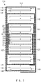
- a second battery according to the present disclosure comprises an electrode assembly 100, an electrolyte (not shown), and a case 130 in which the electrode assembly 100 and the electrolyte are accommodated.
- the electrode assembly 100 comprises a plurality of radical units in which a first electrode and a second electrode are alternately laminated with a separator therebetween and a separation film 130 surrounds the plurality of radical units to be repeatedly laminated.
- the plurality of radical units may be provided as bicells, each of which has both ends, on which electrodes having the same polarity are disposed.
- the first electrode is disposed on each of both the ends of the bicells disposed on the uppermost and lower most ends of the electrode assembly 100.
- the plurality of radical units comprises a first bicell 110 and a second bicell 120.
- the first bicell 110 has a five-layer structure in which the first electrode 10, the separator 20, the second electrode 30, the separator 20, and the first electrode 10 are successively laminated
- the second bicell 120 has a five-layer structure in which the second electrode 30, the separator 20, the first electrode 10, the separator 20, and the second electrode 30 are successively laminated.
- the electrode assembly 100 is formed by alternately laminating the first bicell 110 and the second bicell 120.
- the first bicell is laminated on the outermost portions (the uppermost end and the lowermost end) of the electrode assembly 100.
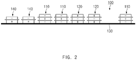
- the separation film 130 is disposed between the first bicell 110 and the second bicell 120 and has a long sheet shape.
- the first bicell 110 and the second bicell 120 are alternately laminated on a top surface of the separation film.
- the first bicell 110, the first bicell 110, the second bicell 120, the second bicell 120, and the first bicell 110 are successively disposed from the left side to the right side. Also, when the separation film 130 is wound from the right side to the left side, as illustrated in FIG.
- the first bicell 110, the second bicell 120, the first bicell 110, the second bicell 120, and the first bicell 110 are successively laminated in the state in which the separation film 130 is disposed therebetween to manufacture the electrode assembly 100.
- a distal end of the separation film may be wound on the outside of the electrode assembly 100, in which the bicells are laminated, at least once to protect the electrode assembly 100.
- the first electrode 10 may be a negative electrode
- the second electrode 30 may be a positive electrode
- the case 200 sealably accommodates the electrode assembly and the electrolyte.
- the case 200 comprises an accommodation part 210 accommodating the electrode assembly 100 and the electrolyte and a sealing part 220 sealably sealing the accommodation part 210.
- the secondary battery according to the present disclosure comprises a protection unit 140 that bypasses, i.e., disperses short-circuit current generated when a nail passes through the electrode assembly to reduce an amount of heat, thereby preventing ignition or explosion from occurring, resulting in securing safety.
- the protection unit 140 has a structure in which the protection unit 140 is laminated on the outermost separation film 130 disposed on the uppermost end or the lowermost end of the electrode assembly 100, and the second protection 141, the separator 142, and the first protection electrode 143 are successively laminated from the outermost separation film 130 disposed on the uppermost end or the lowermost end of the electrode assembly 100.
- the second protection electrode has a cross-sectional coating structure.
- the second protection electrode 141 comprises a second collector 141a and a second electrode active material portion 141b coated with a second electrode active material on an inner surface of the second collector 141a.
- the inner surface of the second collector 141a is a surface facing a center of the electrode assembly 100.
- a non-coating portion, which is not coated with the second electrode active material, is formed on an outer surface of the second collector 141a.
- the second electrode active material portion 141b coated on the inner surface and the first electrode 10 of the first bicell 110 coming into contact with the outermost separation film 130 may interact with each other to increase a battery capacity.
- short-circuit current may be bypassed to the second protection electrode 141 connected through the nail 1, i.e., the entire non-coating portion formed on the outer surface of the second collector 141a of the second protection electrode to reduce an amount of heat, thereby preventing the ignition and explosion from occurring due to a decrease in temperature of the electrode assembly 100, resulting in significantly securing the safety of the secondary battery.
- the first protection electrode 143 is configured to protect the second protection electrode 141 and comprises a first collector 143a and a first electrode active material portion 143b disposed on each of both surfaces of the first collector 143a.
- the first protection electrode 143 may be a negative electrode
- the second protection electrode 141 may be a positive electrode
- the second collector 141a may be configured to stably disperse the short-circuit current and be made of one metal of Cu, Al, Ni, Fe, and Pb. Particularly, the second collector 141a may be made of an Al metal that is capable of greatly improving the dispersion of the short-circuit current.
- the first collector 143a may be made of a Cu metal to more stably protect the second protection electrode 141.
- the protection film 131 may be provided.
- the protection film 131 surround the electrode assembly at least once in the state of comprising the protection unit 140 laminated on the uppermost end or lowermost end of the electrode assembly 100.
- the protection film 131 and the separation film 130 may be made of the same material.
- the protection unit 140 may not be coupled to the outermost separation film 130 of the electrode assembly 100 or may be coupled to the outermost separation film 130 with coupling force that is less than that between the first electrode 10 and the separator 20 or between the second electrode 30 and the separator 20.
- the protection unit 140 may be easily separated from the outermost separation film 130 due to adhesion between the radical unit and the protection unit 140.
- delamination of the electrode of the radical unit and the separator may be prevented by the adhesion between the radical unit and the protection unit 140.
- the electrode assembly 100 When the electrode assembly 100 is accommodated in the case 200, the electrode assembly 100 comprising the protection unit 140 is accommodated in the case 200 in a state in which the protection unit 140 faces an inner surface of the case 200 (for example, faces an inner top or bottom surface when viewed in FIG. 1 ). That is, the protection unit 140 is disposed to face a portion at which possibility of the nail penetration is likely to occur.
- the secondary battery according to the embodiment of the present invention comprises the electrode assembly 100 comprising the protection unit 140 to more effectively disperse the short-circuit current generated when the nail passes through the electrode assembly 100, and thus, the amount of heat of the electrode assembly 100 may be greatly reduced to prevent the ignition or explosion from occurring, thereby securing the safety.
- a secondary battery according to one embodiment of the present invention comprises an electrode assembly 100'.
- the electrode assembly 100' comprises a plurality of radical units in which a first electrode and a second electrode are alternately laminated with a separator therebetween and a separation film 130 surrounds the plurality of radical units to be repeatedly laminated.
- the plurality of radical units may be provided as bicells, each of which has both ends, on which electrodes having the same polarity are disposed.
- the first electrode is disposed on each of both the ends of the bicells disposed on the uppermost and lower most ends of the electrode assembly 100. That is, the plurality of radical units comprises a first bicell 110 and a second bicell 120 (not shown in FIG. 6 ).
- the plurality of radical units may have the same constituent and function as the plurality of radical units according to the first embodiment, and thus, their duplicated description will be omitted.
- the secondary battery according to one embodiment of the present invention comprises a protection unit 140' that bypasses, i.e., disperse short-circuit current generated when a nail passes through the electrode assembly 100' to reduce an amount of heat, thereby preventing ignition or explosion from occurring, resulting in securing safety.
- the protection unit 140' has a structure in which the protection unit 140' is laminated on the outermost separation film 130 disposed on the uppermost end or the lowermost end of the electrode assembly 100', and a second protection 141, a separator 142, and a first protection electrode 143' are successively laminated from the outermost separation film 130 disposed on the uppermost end or the lowermost end of the electrode assembly 100'.
- the second protection electrode 141 comprises a second collector 141a and a second electrode active material portion 141b coated with a second electrode active material on an inner surface of the second collector 141a.
- the inner surface of the second collector 141a may be a surface facing a center of the electrode assembly 100'.
- the first protection electrode 143' has a cross-sectional coating structure comprising a second collector 143a and a first electrode active material portion 143b coated with a first electrode active material on an inner surface of the first collector 143a.
- the inner surface of the first collector 143a may be a surface facing the center of the electrode assembly 100'.
- the protection unit 140' having the above-described configuration has the cross-sectional coating structure in which the electrode active material is applied to only one surface of each of the first and second protection electrodes 143' and 141.
- short-circuit current may be bypassed to the first and second protection electrodes 143' and 141 connected through the nail, more particularly, the first and second collectors 143a and 141a to significantly reduce the amount of heat, thereby significantly reducing in temperature of the electrode assembly 100' and thereby to prevent ignition or explosion from occurring.
- the secondary battery according to one embodiment of the present invention is provided with the electrode assembly 100' comprising the protection unit 140'.
- each of the first and second protection electrodes 143' and 141 of the protection unit 140' has the cross-sectional coating structure on which the electrode active material is applied to only one surface thereof to significantly secure safety of the secondary battery.
- a secondary battery according to one embodiment of the present disclosure comprises a second collector 141a of a second protection electrode 141.
- the second collector 141a has a thickness greater than that of the second collector provided in the second electrode 30 of the radical unit.
- an area of the second collector 141a provided in the second protection electrode 141 may be largely secured to improve dispersion of short-circuit current, thereby more significantly securing safety of the secondary battery.
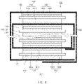
- two or more protection units 140 each of which is laminated on the outermost separation film 130 disposed on the uppermost end or lowermost end of an electrode assembly 100, may be continuously laminated. That is, two or more protection units 140 may be continuously laminated on the outermost separation film 130 to secure safety due to penetration of a nail.
- a protection film 131 surrounds a protection unit 140 laminated on the uppermost end or lowermost end of an electrode assembly 100 in a state in which the protection film 131 is integrally connected to a distal end of the outermost separation film 130.
- two protection units 140 and a plurality of radical units may be disposed on a top surface of a separation film 130 to which a protection film is integrally connected, and then, the separation film 130 may be wound to manufacture a secondary battery 100 on which the protection unit 140 is disposed on the uppermost end or lowermost end thereof.
Landscapes
- Chemical & Material Sciences (AREA)
- Chemical Kinetics & Catalysis (AREA)
- Electrochemistry (AREA)
- General Chemical & Material Sciences (AREA)
- Engineering & Computer Science (AREA)
- Manufacturing & Machinery (AREA)
- Materials Engineering (AREA)
- Secondary Cells (AREA)
- Connection Of Batteries Or Terminals (AREA)
- Battery Electrode And Active Subsutance (AREA)
Priority Applications (1)
| Application Number | Priority Date | Filing Date | Title |
|---|---|---|---|
| PL20189372T PL3754773T3 (pl) | 2017-07-06 | 2018-05-04 | Bateria akumulatorowa |
Applications Claiming Priority (3)
| Application Number | Priority Date | Filing Date | Title |
|---|---|---|---|
| KR1020170086050A KR102217447B1 (ko) | 2017-07-06 | 2017-07-06 | 이차전지 |
| PCT/KR2018/005213 WO2019009511A1 (ko) | 2017-07-06 | 2018-05-04 | 이차전지 |
| EP18828206.5A EP3503279B1 (en) | 2017-07-06 | 2018-05-04 | Secondary battery |
Related Parent Applications (2)
| Application Number | Title | Priority Date | Filing Date |
|---|---|---|---|
| EP18828206.5A Division-Into EP3503279B1 (en) | 2017-07-06 | 2018-05-04 | Secondary battery |
| EP18828206.5A Division EP3503279B1 (en) | 2017-07-06 | 2018-05-04 | Secondary battery |
Publications (2)
| Publication Number | Publication Date |
|---|---|
| EP3754773A1 EP3754773A1 (en) | 2020-12-23 |
| EP3754773B1 true EP3754773B1 (en) | 2022-04-13 |
Family
ID=64951131
Family Applications (2)
| Application Number | Title | Priority Date | Filing Date |
|---|---|---|---|
| EP20189372.4A Active EP3754773B1 (en) | 2017-07-06 | 2018-05-04 | Secondary battery |
| EP18828206.5A Active EP3503279B1 (en) | 2017-07-06 | 2018-05-04 | Secondary battery |
Family Applications After (1)
| Application Number | Title | Priority Date | Filing Date |
|---|---|---|---|
| EP18828206.5A Active EP3503279B1 (en) | 2017-07-06 | 2018-05-04 | Secondary battery |
Country Status (7)
| Country | Link |
|---|---|
| US (2) | US11177519B2 (pl) |
| EP (2) | EP3754773B1 (pl) |
| JP (1) | JP6787544B2 (pl) |
| KR (1) | KR102217447B1 (pl) |
| CN (1) | CN109792074B (pl) |
| PL (2) | PL3754773T3 (pl) |
| WO (1) | WO2019009511A1 (pl) |
Cited By (1)
| Publication number | Priority date | Publication date | Assignee | Title |
|---|---|---|---|---|
| EP4312283A1 (en) * | 2022-07-22 | 2024-01-31 | Samsung SDI Co., Ltd. | Lithium battery and preparation method thereof |
Families Citing this family (5)
| Publication number | Priority date | Publication date | Assignee | Title |
|---|---|---|---|---|
| CN109860716A (zh) * | 2019-01-15 | 2019-06-07 | 东莞市佳的自动化设备科技有限公司 | 一种电池叠片结构及其生产方法与应用 |
| CN109888360B (zh) * | 2019-01-26 | 2021-08-27 | 温在东 | 叠片电芯结构及适于其分体式叠片、贴胶的生产方法 |
| CN109768316B (zh) * | 2019-01-26 | 2021-08-27 | 温在东 | 叠片电芯结构及适于其贯通式叠片、贴胶的生产方法 |
| KR102900615B1 (ko) * | 2020-10-08 | 2025-12-15 | 주식회사 엘지에너지솔루션 | 전극조립체의 적층 불량 검출 방법, 절연 부재를 포함하는 전극조립체 및 이를 포함하는 전지 셀 |
| CN117855622A (zh) * | 2024-01-04 | 2024-04-09 | 合肥国轩高科动力能源有限公司 | 叠片电芯、叠片电芯的制备方法及制备系统 |
Family Cites Families (23)
| Publication number | Priority date | Publication date | Assignee | Title |
|---|---|---|---|---|
| JP4432244B2 (ja) * | 2000-09-29 | 2010-03-17 | 三菱化学株式会社 | 平板積層型電池 |
| KR100958649B1 (ko) | 2002-12-27 | 2010-05-20 | 삼성에스디아이 주식회사 | 전지부와, 이의 감는 방법과, 이를 채용하여 제조된 리튬이차 전지 |
| KR100611940B1 (ko) | 2003-11-21 | 2006-08-11 | 주식회사 엘지화학 | 안전성이 향상된 전기화학 전지 |
| KR100861705B1 (ko) * | 2006-05-29 | 2008-10-06 | 주식회사 엘지화학 | 구조적 안정성과 전해액의 젖음성이 우수한 전극조립체 및이를 포함하는 이차전지 |
| KR101014817B1 (ko) * | 2007-12-14 | 2011-02-14 | 주식회사 엘지화학 | 안전 부재를 포함하고 있는 스택/폴딩형 전극조립체 및그것의 제조방법 |
| KR101065883B1 (ko) * | 2009-10-15 | 2011-09-19 | 삼성에스디아이 주식회사 | 이차 전지용 전극조립체, 그 제조방법 및 그 전극조립체를 구비하는 이차전지 |
| KR101310482B1 (ko) | 2010-10-19 | 2013-09-24 | 주식회사 엘지화학 | 안전성이 향상된 신규 구조의 전기소자 |
| KR101367754B1 (ko) * | 2011-07-07 | 2014-02-27 | 주식회사 엘지화학 | 전기화학소자용 전극 조립체 및 이를 구비한 전기화학소자 |
| KR20130118716A (ko) | 2012-04-20 | 2013-10-30 | 주식회사 엘지화학 | 전극 조립체, 이를 포함하는 전지셀 및 디바이스 |
| KR101484525B1 (ko) * | 2012-05-07 | 2015-01-20 | 주식회사 엘지화학 | 전극 적층체 및 이를 포함하는 리튬 이차전지 |
| KR20130132231A (ko) * | 2012-05-25 | 2013-12-04 | 주식회사 엘지화학 | 단차를 갖는 전극 조립체 및 이를 포함하는 전지셀, 전지팩 및 디바이스 |
| KR101693289B1 (ko) | 2012-07-31 | 2017-01-06 | 삼성에스디아이 주식회사 | 이차 전지 |
| JP2014110209A (ja) * | 2012-12-04 | 2014-06-12 | Toyota Industries Corp | 蓄電装置 |
| EP2814103B1 (en) * | 2013-02-15 | 2017-12-06 | LG Chem, Ltd. | Electrode assembly and polymer secondary battery cell comprising same |
| KR101617423B1 (ko) | 2014-01-06 | 2016-05-03 | 주식회사 엘지화학 | 계단 구조의 하이브리드 전극조립체 |
| WO2015105369A1 (ko) * | 2014-01-10 | 2015-07-16 | 주식회사 엘지화학 | 안전 분리막을 가진 전극조립체 및 이를 포함하는 이차전지 |
| KR101744120B1 (ko) | 2014-08-11 | 2017-06-07 | 주식회사 엘지화학 | 침상 관통 테스트 안전성이 향상된 파우치형 이차전지 |
| KR101756864B1 (ko) * | 2014-10-01 | 2017-07-11 | 주식회사 엘지화학 | 두께가 두꺼운 집전체를 포함하는 전극조립체 및 이를 포함하는 리튬 이차전지 |
| KR101791674B1 (ko) | 2014-10-31 | 2017-10-30 | 주식회사 엘지화학 | 바이셀과 풀셀을 포함하는 전극조립체 및 이를 포함하는 이차전지 |
| JP6583711B2 (ja) | 2015-03-17 | 2019-10-02 | 株式会社Gsユアサ | 蓄電素子 |
| KR102048755B1 (ko) * | 2015-08-17 | 2019-11-26 | 주식회사 엘지화학 | 분리막 시트에 의해 권취된 구조의 단위셀을 포함하는 전극조립체 |
| KR102025564B1 (ko) | 2015-08-21 | 2019-09-26 | 주식회사 엘지화학 | 전지 소자들 사이에 개재되어 있는 단위셀을 포함하는 전극조립체 |
| KR102080253B1 (ko) | 2015-11-06 | 2020-02-24 | 주식회사 엘지화학 | 전극 조립체 |
-
2017
- 2017-07-06 KR KR1020170086050A patent/KR102217447B1/ko active Active
-
2018
- 2018-05-04 PL PL20189372T patent/PL3754773T3/pl unknown
- 2018-05-04 US US16/332,978 patent/US11177519B2/en active Active
- 2018-05-04 WO PCT/KR2018/005213 patent/WO2019009511A1/ko not_active Ceased
- 2018-05-04 PL PL18828206T patent/PL3503279T3/pl unknown
- 2018-05-04 EP EP20189372.4A patent/EP3754773B1/en active Active
- 2018-05-04 JP JP2019520355A patent/JP6787544B2/ja active Active
- 2018-05-04 CN CN201880003697.4A patent/CN109792074B/zh active Active
- 2018-05-04 EP EP18828206.5A patent/EP3503279B1/en active Active
-
2021
- 2021-10-27 US US17/512,227 patent/US11728466B2/en active Active
Cited By (1)
| Publication number | Priority date | Publication date | Assignee | Title |
|---|---|---|---|---|
| EP4312283A1 (en) * | 2022-07-22 | 2024-01-31 | Samsung SDI Co., Ltd. | Lithium battery and preparation method thereof |
Also Published As
| Publication number | Publication date |
|---|---|
| US11728466B2 (en) | 2023-08-15 |
| US11177519B2 (en) | 2021-11-16 |
| EP3503279A1 (en) | 2019-06-26 |
| EP3503279B1 (en) | 2020-09-16 |
| EP3503279A4 (en) | 2019-11-13 |
| PL3754773T3 (pl) | 2022-06-20 |
| JP6787544B2 (ja) | 2020-11-18 |
| KR20190005425A (ko) | 2019-01-16 |
| US20190273224A1 (en) | 2019-09-05 |
| KR102217447B1 (ko) | 2021-02-22 |
| WO2019009511A1 (ko) | 2019-01-10 |
| PL3503279T3 (pl) | 2021-03-08 |
| EP3754773A1 (en) | 2020-12-23 |
| CN109792074B (zh) | 2022-03-04 |
| JP2019532474A (ja) | 2019-11-07 |
| CN109792074A (zh) | 2019-05-21 |
| US20220052400A1 (en) | 2022-02-17 |
Similar Documents
| Publication | Publication Date | Title |
|---|---|---|
| EP3754773B1 (en) | Secondary battery | |
| EP3712997B1 (en) | Electrode assembly | |
| KR102401809B1 (ko) | 배터리 셀용 전극 유닛의 제조 방법, 그리고 전극 유닛 | |
| EP3242346B1 (en) | Electrode assembly | |
| KR101036067B1 (ko) | 안전부재가 구비된 파우치형 리튬 이차전지 | |
| EP3246979B1 (en) | Rechargeable battery | |
| EP3048656B1 (en) | Rechargeable battery | |
| EP3273510B1 (en) | Rechargeable battery | |
| KR101789066B1 (ko) | 복합 구조의 전극 조립체 및 상기 전극 조립체를 갖는 리튬이온 이차전지 | |
| US10862097B2 (en) | Secondary battery | |
| CN214589019U (zh) | 电池及用电设备 | |
| EP4080644A1 (en) | Electrode assembly comprising disconnection prevention layer, and preparation method thereof | |
| US20140255757A1 (en) | Rechargeable battery | |
| KR102006203B1 (ko) | 절연성이 개선된 파우치 외장 부재 및 이를 포함하는 파우치형 이차 전지 | |
| EP3605661B1 (en) | ELECTRODE, ASSOCIATED MANUFACTURING PROCESS, ELECTRODE AND RECHARGEABLE BATTERY ASSEMBLY | |
| EP3582314B1 (en) | Electrode assembly and method for manufacturing the same | |
| US11967734B2 (en) | Electrode assembly, secondary battery comprising the same, method for manufacturing secondary battery, and battery pack | |
| CN115117458B (zh) | 电芯及电池 | |
| KR20150049635A (ko) | 이차전지 | |
| EP4243194B1 (en) | Pouch-shaped battery cell with improved thermal stability | |
| US20240186660A1 (en) | Electrode tab assembly and secondary battery including the same | |
| KR20260004106A (ko) | 배터리 팩 | |
| KR20250098576A (ko) | 배터리 셀 | |
| KR101566574B1 (ko) | 물과 무기산화물의 혼합물을 적용한 고안전성 리튬 이차전지 | |
| KR20180103595A (ko) | 전극조립체 |
Legal Events
| Date | Code | Title | Description |
|---|---|---|---|
| PUAI | Public reference made under article 153(3) epc to a published international application that has entered the european phase |
Free format text: ORIGINAL CODE: 0009012 |
|
| STAA | Information on the status of an ep patent application or granted ep patent |
Free format text: STATUS: REQUEST FOR EXAMINATION WAS MADE |
|
| 17P | Request for examination filed |
Effective date: 20200804 |
|
| AC | Divisional application: reference to earlier application |
Ref document number: 3503279 Country of ref document: EP Kind code of ref document: P |
|
| AK | Designated contracting states |
Kind code of ref document: A1 Designated state(s): AL AT BE BG CH CY CZ DE DK EE ES FI FR GB GR HR HU IE IS IT LI LT LU LV MC MK MT NL NO PL PT RO RS SE SI SK SM TR |
|
| RIC1 | Information provided on ipc code assigned before grant |
Ipc: H01M 50/572 20210101ALI20210930BHEP Ipc: H01M 50/10 20210101ALI20210930BHEP Ipc: H01M 4/66 20060101ALI20210930BHEP Ipc: H01M 10/42 20060101ALI20210930BHEP Ipc: H01M 10/0583 20100101ALI20210930BHEP Ipc: H01M 10/04 20060101AFI20210930BHEP |
|
| GRAP | Despatch of communication of intention to grant a patent |
Free format text: ORIGINAL CODE: EPIDOSNIGR1 |
|
| STAA | Information on the status of an ep patent application or granted ep patent |
Free format text: STATUS: GRANT OF PATENT IS INTENDED |
|
| INTG | Intention to grant announced |
Effective date: 20211109 |
|
| RAP1 | Party data changed (applicant data changed or rights of an application transferred) |
Owner name: LG ENERGY SOLUTION LTD. |
|
| GRAS | Grant fee paid |
Free format text: ORIGINAL CODE: EPIDOSNIGR3 |
|
| GRAA | (expected) grant |
Free format text: ORIGINAL CODE: 0009210 |
|
| STAA | Information on the status of an ep patent application or granted ep patent |
Free format text: STATUS: THE PATENT HAS BEEN GRANTED |
|
| RAP3 | Party data changed (applicant data changed or rights of an application transferred) |
Owner name: LG ENERGY SOLUTION, LTD. |
|
| AC | Divisional application: reference to earlier application |
Ref document number: 3503279 Country of ref document: EP Kind code of ref document: P |
|
| AK | Designated contracting states |
Kind code of ref document: B1 Designated state(s): AL AT BE BG CH CY CZ DE DK EE ES FI FR GB GR HR HU IE IS IT LI LT LU LV MC MK MT NL NO PL PT RO RS SE SI SK SM TR |
|
| REG | Reference to a national code |
Ref country code: GB Ref legal event code: FG4D |
|
| REG | Reference to a national code |
Ref country code: CH Ref legal event code: EP |
|
| REG | Reference to a national code |
Ref country code: DE Ref legal event code: R096 Ref document number: 602018033988 Country of ref document: DE |
|
| REG | Reference to a national code |
Ref country code: IE Ref legal event code: FG4D |
|
| REG | Reference to a national code |
Ref country code: AT Ref legal event code: REF Ref document number: 1484112 Country of ref document: AT Kind code of ref document: T Effective date: 20220515 |
|
| REG | Reference to a national code |
Ref country code: SE Ref legal event code: TRGR |
|
| REG | Reference to a national code |
Ref country code: LT Ref legal event code: MG9D |
|
| REG | Reference to a national code |
Ref country code: NL Ref legal event code: MP Effective date: 20220413 |
|
| REG | Reference to a national code |
Ref country code: AT Ref legal event code: MK05 Ref document number: 1484112 Country of ref document: AT Kind code of ref document: T Effective date: 20220413 |
|
| PG25 | Lapsed in a contracting state [announced via postgrant information from national office to epo] |
Ref country code: NL Free format text: LAPSE BECAUSE OF FAILURE TO SUBMIT A TRANSLATION OF THE DESCRIPTION OR TO PAY THE FEE WITHIN THE PRESCRIBED TIME-LIMIT Effective date: 20220413 |
|
| PG25 | Lapsed in a contracting state [announced via postgrant information from national office to epo] |
Ref country code: PT Free format text: LAPSE BECAUSE OF FAILURE TO SUBMIT A TRANSLATION OF THE DESCRIPTION OR TO PAY THE FEE WITHIN THE PRESCRIBED TIME-LIMIT Effective date: 20220816 Ref country code: NO Free format text: LAPSE BECAUSE OF FAILURE TO SUBMIT A TRANSLATION OF THE DESCRIPTION OR TO PAY THE FEE WITHIN THE PRESCRIBED TIME-LIMIT Effective date: 20220713 Ref country code: LT Free format text: LAPSE BECAUSE OF FAILURE TO SUBMIT A TRANSLATION OF THE DESCRIPTION OR TO PAY THE FEE WITHIN THE PRESCRIBED TIME-LIMIT Effective date: 20220413 Ref country code: HR Free format text: LAPSE BECAUSE OF FAILURE TO SUBMIT A TRANSLATION OF THE DESCRIPTION OR TO PAY THE FEE WITHIN THE PRESCRIBED TIME-LIMIT Effective date: 20220413 Ref country code: GR Free format text: LAPSE BECAUSE OF FAILURE TO SUBMIT A TRANSLATION OF THE DESCRIPTION OR TO PAY THE FEE WITHIN THE PRESCRIBED TIME-LIMIT Effective date: 20220714 Ref country code: FI Free format text: LAPSE BECAUSE OF FAILURE TO SUBMIT A TRANSLATION OF THE DESCRIPTION OR TO PAY THE FEE WITHIN THE PRESCRIBED TIME-LIMIT Effective date: 20220413 Ref country code: ES Free format text: LAPSE BECAUSE OF FAILURE TO SUBMIT A TRANSLATION OF THE DESCRIPTION OR TO PAY THE FEE WITHIN THE PRESCRIBED TIME-LIMIT Effective date: 20220413 Ref country code: BG Free format text: LAPSE BECAUSE OF FAILURE TO SUBMIT A TRANSLATION OF THE DESCRIPTION OR TO PAY THE FEE WITHIN THE PRESCRIBED TIME-LIMIT Effective date: 20220713 Ref country code: AT Free format text: LAPSE BECAUSE OF FAILURE TO SUBMIT A TRANSLATION OF THE DESCRIPTION OR TO PAY THE FEE WITHIN THE PRESCRIBED TIME-LIMIT Effective date: 20220413 |
|
| PG25 | Lapsed in a contracting state [announced via postgrant information from national office to epo] |
Ref country code: RS Free format text: LAPSE BECAUSE OF FAILURE TO SUBMIT A TRANSLATION OF THE DESCRIPTION OR TO PAY THE FEE WITHIN THE PRESCRIBED TIME-LIMIT Effective date: 20220413 Ref country code: LV Free format text: LAPSE BECAUSE OF FAILURE TO SUBMIT A TRANSLATION OF THE DESCRIPTION OR TO PAY THE FEE WITHIN THE PRESCRIBED TIME-LIMIT Effective date: 20220413 Ref country code: IS Free format text: LAPSE BECAUSE OF FAILURE TO SUBMIT A TRANSLATION OF THE DESCRIPTION OR TO PAY THE FEE WITHIN THE PRESCRIBED TIME-LIMIT Effective date: 20220813 |
|
| REG | Reference to a national code |
Ref country code: CH Ref legal event code: PL |
|
| REG | Reference to a national code |
Ref country code: DE Ref legal event code: R097 Ref document number: 602018033988 Country of ref document: DE |
|
| REG | Reference to a national code |
Ref country code: BE Ref legal event code: MM Effective date: 20220531 |
|
| PG25 | Lapsed in a contracting state [announced via postgrant information from national office to epo] |
Ref country code: SM Free format text: LAPSE BECAUSE OF FAILURE TO SUBMIT A TRANSLATION OF THE DESCRIPTION OR TO PAY THE FEE WITHIN THE PRESCRIBED TIME-LIMIT Effective date: 20220413 Ref country code: SK Free format text: LAPSE BECAUSE OF FAILURE TO SUBMIT A TRANSLATION OF THE DESCRIPTION OR TO PAY THE FEE WITHIN THE PRESCRIBED TIME-LIMIT Effective date: 20220413 Ref country code: RO Free format text: LAPSE BECAUSE OF FAILURE TO SUBMIT A TRANSLATION OF THE DESCRIPTION OR TO PAY THE FEE WITHIN THE PRESCRIBED TIME-LIMIT Effective date: 20220413 Ref country code: MC Free format text: LAPSE BECAUSE OF FAILURE TO SUBMIT A TRANSLATION OF THE DESCRIPTION OR TO PAY THE FEE WITHIN THE PRESCRIBED TIME-LIMIT Effective date: 20220413 Ref country code: LU Free format text: LAPSE BECAUSE OF NON-PAYMENT OF DUE FEES Effective date: 20220504 Ref country code: LI Free format text: LAPSE BECAUSE OF NON-PAYMENT OF DUE FEES Effective date: 20220531 Ref country code: EE Free format text: LAPSE BECAUSE OF FAILURE TO SUBMIT A TRANSLATION OF THE DESCRIPTION OR TO PAY THE FEE WITHIN THE PRESCRIBED TIME-LIMIT Effective date: 20220413 Ref country code: DK Free format text: LAPSE BECAUSE OF FAILURE TO SUBMIT A TRANSLATION OF THE DESCRIPTION OR TO PAY THE FEE WITHIN THE PRESCRIBED TIME-LIMIT Effective date: 20220413 Ref country code: CZ Free format text: LAPSE BECAUSE OF FAILURE TO SUBMIT A TRANSLATION OF THE DESCRIPTION OR TO PAY THE FEE WITHIN THE PRESCRIBED TIME-LIMIT Effective date: 20220413 Ref country code: CH Free format text: LAPSE BECAUSE OF NON-PAYMENT OF DUE FEES Effective date: 20220531 |
|
| PLBE | No opposition filed within time limit |
Free format text: ORIGINAL CODE: 0009261 |
|
| STAA | Information on the status of an ep patent application or granted ep patent |
Free format text: STATUS: NO OPPOSITION FILED WITHIN TIME LIMIT |
|
| 26N | No opposition filed |
Effective date: 20230116 |
|
| PG25 | Lapsed in a contracting state [announced via postgrant information from national office to epo] |
Ref country code: AL Free format text: LAPSE BECAUSE OF FAILURE TO SUBMIT A TRANSLATION OF THE DESCRIPTION OR TO PAY THE FEE WITHIN THE PRESCRIBED TIME-LIMIT Effective date: 20220413 |
|
| PG25 | Lapsed in a contracting state [announced via postgrant information from national office to epo] |
Ref country code: IE Free format text: LAPSE BECAUSE OF NON-PAYMENT OF DUE FEES Effective date: 20220504 |
|
| PG25 | Lapsed in a contracting state [announced via postgrant information from national office to epo] |
Ref country code: SI Free format text: LAPSE BECAUSE OF FAILURE TO SUBMIT A TRANSLATION OF THE DESCRIPTION OR TO PAY THE FEE WITHIN THE PRESCRIBED TIME-LIMIT Effective date: 20220413 Ref country code: BE Free format text: LAPSE BECAUSE OF NON-PAYMENT OF DUE FEES Effective date: 20220531 |
|
| P01 | Opt-out of the competence of the unified patent court (upc) registered |
Effective date: 20230512 |
|
| PG25 | Lapsed in a contracting state [announced via postgrant information from national office to epo] |
Ref country code: IT Free format text: LAPSE BECAUSE OF FAILURE TO SUBMIT A TRANSLATION OF THE DESCRIPTION OR TO PAY THE FEE WITHIN THE PRESCRIBED TIME-LIMIT Effective date: 20220413 |
|
| PG25 | Lapsed in a contracting state [announced via postgrant information from national office to epo] |
Ref country code: MK Free format text: LAPSE BECAUSE OF FAILURE TO SUBMIT A TRANSLATION OF THE DESCRIPTION OR TO PAY THE FEE WITHIN THE PRESCRIBED TIME-LIMIT Effective date: 20220413 Ref country code: CY Free format text: LAPSE BECAUSE OF FAILURE TO SUBMIT A TRANSLATION OF THE DESCRIPTION OR TO PAY THE FEE WITHIN THE PRESCRIBED TIME-LIMIT Effective date: 20220413 |
|
| PG25 | Lapsed in a contracting state [announced via postgrant information from national office to epo] |
Ref country code: HU Free format text: LAPSE BECAUSE OF FAILURE TO SUBMIT A TRANSLATION OF THE DESCRIPTION OR TO PAY THE FEE WITHIN THE PRESCRIBED TIME-LIMIT; INVALID AB INITIO Effective date: 20180504 |
|
| PG25 | Lapsed in a contracting state [announced via postgrant information from national office to epo] |
Ref country code: TR Free format text: LAPSE BECAUSE OF FAILURE TO SUBMIT A TRANSLATION OF THE DESCRIPTION OR TO PAY THE FEE WITHIN THE PRESCRIBED TIME-LIMIT Effective date: 20220413 |
|
| PG25 | Lapsed in a contracting state [announced via postgrant information from national office to epo] |
Ref country code: MT Free format text: LAPSE BECAUSE OF FAILURE TO SUBMIT A TRANSLATION OF THE DESCRIPTION OR TO PAY THE FEE WITHIN THE PRESCRIBED TIME-LIMIT Effective date: 20220413 |
|
| PG25 | Lapsed in a contracting state [announced via postgrant information from national office to epo] |
Ref country code: BG Free format text: LAPSE BECAUSE OF FAILURE TO SUBMIT A TRANSLATION OF THE DESCRIPTION OR TO PAY THE FEE WITHIN THE PRESCRIBED TIME-LIMIT Effective date: 20220413 |
|
| PG25 | Lapsed in a contracting state [announced via postgrant information from national office to epo] |
Ref country code: BG Free format text: LAPSE BECAUSE OF FAILURE TO SUBMIT A TRANSLATION OF THE DESCRIPTION OR TO PAY THE FEE WITHIN THE PRESCRIBED TIME-LIMIT Effective date: 20220413 |
|
| PGFP | Annual fee paid to national office [announced via postgrant information from national office to epo] |
Ref country code: DE Payment date: 20250422 Year of fee payment: 8 Ref country code: PL Payment date: 20250423 Year of fee payment: 8 |
|
| PGFP | Annual fee paid to national office [announced via postgrant information from national office to epo] |
Ref country code: GB Payment date: 20250422 Year of fee payment: 8 |
|
| PGFP | Annual fee paid to national office [announced via postgrant information from national office to epo] |
Ref country code: FR Payment date: 20250422 Year of fee payment: 8 |
|
| PGFP | Annual fee paid to national office [announced via postgrant information from national office to epo] |
Ref country code: SE Payment date: 20250422 Year of fee payment: 8 |