EP3754342B1 - Anstellwinkelsensor - Google Patents
Anstellwinkelsensor Download PDFInfo
- Publication number
- EP3754342B1 EP3754342B1 EP19216057.0A EP19216057A EP3754342B1 EP 3754342 B1 EP3754342 B1 EP 3754342B1 EP 19216057 A EP19216057 A EP 19216057A EP 3754342 B1 EP3754342 B1 EP 3754342B1
- Authority
- EP
- European Patent Office
- Prior art keywords
- vane shaft
- vane
- angle
- attack sensor
- vent hole
- Prior art date
- Legal status (The legal status is an assumption and is not a legal conclusion. Google has not performed a legal analysis and makes no representation as to the accuracy of the status listed.)
- Active
Links
Images



Classifications
-
- G—PHYSICS
- G01—MEASURING; TESTING
- G01P—MEASURING LINEAR OR ANGULAR SPEED, ACCELERATION, DECELERATION, OR SHOCK; INDICATING PRESENCE, ABSENCE, OR DIRECTION, OF MOVEMENT
- G01P13/00—Indicating or recording presence, absence, or direction, of movement
- G01P13/02—Indicating direction only, e.g. by weather vane
- G01P13/025—Indicating direction only, e.g. by weather vane indicating air data, i.e. flight variables of an aircraft, e.g. angle of attack, side slip, shear, yaw
-
- B—PERFORMING OPERATIONS; TRANSPORTING
- B64—AIRCRAFT; AVIATION; COSMONAUTICS
- B64D—EQUIPMENT FOR FITTING IN OR TO AIRCRAFT; FLIGHT SUITS; PARACHUTES; ARRANGEMENT OR MOUNTING OF POWER PLANTS OR PROPULSION TRANSMISSIONS IN AIRCRAFT
- B64D43/00—Arrangements or adaptations of instruments
- B64D43/02—Arrangements or adaptations of instruments for indicating aircraft speed or stalling conditions
Definitions
- the present disclosure relates to sensors, and in particular, to angle of attack sensors.
- Angle of attack sensors with rotatable vanes are installed on sides of aircraft to measure the aircraft angle of attack, the angle between oncoming airflow and the aircraft zero line (a reference line of the aircraft, such as a chord of a wing of the aircraft).
- the angle of attack sensor is mounted to the aircraft such that the rotatable vane protrudes outside the aircraft and is exposed to oncoming airflow. Aerodynamic forces acting on the rotatable vane cause the vane to align with the direction of the oncoming airflow. Rotational position of the vane is sensed and used to determine the aircraft angle of attack.
- Angle of attack sensors are discloses in US 3,534,600 and US 3,882,721 .
- An angle of attack sensor is provided as defined by claim 1.
- a vane shaft for an angle of attack sensor includes a body portion, a top portion connected to an end of the body portion, the top portion being configured to connect to a vane assembly, a bore extending through the body portion and the top portion, and a first vent hole extending through the body portion from the bore to an exterior surface of the vane shaft.
- a method of directing airflow through an angle of attack sensor is provided as defined by claim 10.
- the present disclosure describes an angle of attack sensor that has a vent hole in the vane shaft beneath a lip of the vane shaft seal and above the bearing to direct venting airflow through a center bore of the vane shaft and past the vane shaft seal, resulting in a sealed breathing path where the venting airflow bypasses the bearing. Consequently, the bearing is not subjected to contaminants and water in the airflow, preventing the bearing from freezing and increasing the life of the angle of attack sensor.
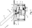
- FIG. 1 is a partial cross-sectional view of angle of attack sensor 10.
- Angle of attack sensor 10 includes faceplate 12, housing 14, mounting holes 16, opening 18, vane assembly 20 (including vane 22 and vane base 24), annular gap 26, vane shaft 28, o-ring 30, counterweight 32, resolver 34, and electronics 36. Vane assembly 20, counterweight 32, and resolver 34 are not shown in cross-section in FIG. 1 .
- Faceplate 12 is a faceplate of angle of attack sensor 10. Faceplate 12 is positioned on and connected to housing 14. Housing 14 is cylindrical with an annular sidewall between an open first end and a closed second end. Faceplate 12 is positioned on the open first end of housing 14 such that a portion of faceplate 12 extends within the open first end of housing 14. Faceplate 12 is sealed to housing 14. Mounting holes 16 extend through faceplate 12 from a first surface of faceplate 12 to a second surface of faceplate 12. Mounting holes 16 are positioned near a periphery of faceplate 12. Opening 18 is a circular opening at a center of faceplate 12. Vane assembly 20 extends through opening 18 of faceplate 12. Vane assembly 20 has vane 22 connected to vane base 24 at a first end of vane 22.
- Vane base 24 is positioned in opening 18.
- Annular gap 26 is adjacent vane base 24.
- Annular gap 26 is a space that surrounds vane base 24.
- annular gap 26 is between vane base 24 and faceplate 12. Consequently, annular gap 26 acts as a representation of the boundary between parts that rotate, such as vane 22 and vane base 24, and parts that do not rotate, such as faceplate 12.
- a first end of rotatable vane shaft 28 is connected to vane base 24.
- Vane shaft 28 extends through faceplate 12 into and within housing 14.
- O-ring 30 is positioned in a groove in the first end of vane shaft 28 such that o-ring 30 is between vane base 24 and the first end of vane shaft 28.
- Counterweight 32 is mounted on the second end of vane shaft 28.
- vane base 24, vane shaft 28, and counterweight 32 are configured to rotate together.
- Resolver 34 is connected to vane shaft 28 via a resolver shaft.
- Resolver 34 is positioned within housing 14.
- Electronics 36 are positioned adjacent resolver 34 and connected to resolver 34 within housing 14.
- Angle of attack sensors 10 are installed on the exterior of an aircraft and mounted to the aircraft via fasteners, such as screws or bolts, through mounting holes 16 on faceplate 12.
- faceplate 12 is in line with with the skin of the aircraft and housing 14 extends within an interior of the aircraft.
- Vane 22 extends outside an exterior of aircraft and is exposed to oncoming airflow, causing vane 22 and vane base 24 of vane assembly 20 to rotate with respect to faceplate 12 via a series of bearings within angle of attack sensor 10.
- Vane 22 rotates based on the angle the aircraft is flying at relative to the oncoming airflow. More specifically, vane 22 rotates to be parallel with oncoming airflow. Vane 22 causes vane base 24 to rotate, which causes rotation of vane shaft 28.
- Rotation of vane shaft 28 is sensed by resolver 34 and used to measure the local angle of attack, or angle of the airflow relative to the fixed aircraft structure.
- O-ring 30 impedes water ingress between vane base 24 and vane shaft 28.
- Counterweight 32 is mounted on vane shaft 28 to counterbalance vane 22.
- Electronics 36 power electronic components of angle of attack sensor 10, such as resolver 34.
- FIG. 2A is an enlarged partial cross-sectional view of a portion of angle of attack sensor 10.
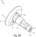
- FIG. 2B is an isometric view of vane shaft 28.
- FIG. 2C is a side view of vane shaft 28.
- FIG. 2D is a cross-sectional isometric view of vane shaft 28.
- Angle of attack sensor 10 includes faceplate 12, opening 18, vane assembly 20 (including vane 22 and vane base 24), annular gap 26, vane shaft 28, o-ring 30, counterweight 32, bearing 38, and vane shaft seal 40 (which includes sealing element 42 having lip 44).
- Vane shaft 28 includes first end 46, second end 48, body portion 50, top portion 52, bore 54, interior surface 56, exterior surface 58, and vent holes 60A and 60B (shown in FIG. 2D ).
- Angle of attack sensor 10 has the same structure and function as angle of attack sensor 10 described in reference to FIG. 1 .
- Bearing 38 is positioned around vane shaft 28 such that bearing 38 surrounds vane shaft 28.
- Vane shaft seal 40 is positioned around vane shaft 28 above bearing 38 such that vane shaft seal 40 surrounds vane shaft 28.
- a bottom, or end, of vane shaft seal 40 contacts a top, or end, of bearing 38.
- Vane shaft seal 40 is adjacent bearing 38 and between bearing 38 and vane assembly 20.
- Vane shaft seal 40 is an annular seal.
- Vane shaft seal 40 has annular sealing element 42 with annular lip 44 in contact with vane shaft 28.
- a top, or end, of lip 44 makes up a top, or end, of vane shaft seal 40.
- Vane shaft seal 40 is a light seal.
- lip 44 of sealing element 42 of vane shaft seal 40 contacts vane shaft 28 and seals against vane shaft 28, but may also move away from vane shaft 28 due to airflow within angle of attack sensor 10.
- Vane shaft 28 has first end 46, which is connected to vane base 24, and second end 48, which is within housing 14 and connected to counterweight 32.
- Vane shaft 28 has body portion 50 and top portion 52 connected to body portion 50.
- a first end of top portion 52 makes up first end 46 of vane shaft 28, a second end of top portion 52 is connected to a first end of body portion 50, and a second end of body portion 50 makes up second end 48 of vane shaft 28.
- Body portion 50 is narrower than top portion 52.
- Vane shaft seal 40 contacts body portion 50 of vane shaft 28.
- Top portion 52 is connected to vane base 24.
- Bore 54 is a passageway that extends through vane shaft 28 from first end 46 to second end 48 such that bore 54 extends through body portion 50 and top portion 52 of vane shaft 28.
- Bore 54 is defined by interior surface 56.
- Interior surface 56 is a surface at the inside, and primarily at the center, of vane shaft 28.
- Exterior surface 58 is a surface at the outside of
- Vent hole 60A is at a first side of vane shaft 28 and vent hole 60B is at a second side of vane shaft 28. In this embodiment, vent hole 60A is 180 degrees from vent hole 60B. In alternate embodiments, vent holes 60A and 60B may be any distance apart. Vent holes 60A and 60B extend through body portion 50 of vane shaft 28 from interior surface 56 to exterior surface 58. As such, vent holes 60A and 60B are in fluid communication with bore 54 of vane shaft 28 and extend from bore 54 to exterior surface 58.
- Vent holes 60A and 60B extend through body portion 50 of vane shaft 28 above bearing 38 and below lip 44 of sealing element 42 of vane shaft seal 40, or adjacent top portion 52, so that vent holes 60A and 60B are between bearing 38 and a top, or end, of vane shaft seal 40. Vent holes 60A and 60B do not contact vane shaft seal 40.
- angle of attack sensor 10 may include one or more than two vent holes 60.
- Body portion 50 may have other passageways extending from exterior surface 58 into bore 54.
- Vane shaft seal 40 acts as a retainer for bearing 38, keeping bearing 38 from backing out of angle of attack sensor 10. Lip 44 of sealing element 42 of vane shaft seal 40 is positioned against vane shaft 28 to provide sealing at vane shaft 28. Vane shaft seal 40 is a light seal so as to not restrict movement of vane shaft 28, which would interfere with the functionality of angle of attack sensor 10. Vane shaft seal 40 allows free rotation of vane assembly 20. Because vane shaft seal 40 is a light seal, lip 44 will move away from vane shaft 28 to allow airflow to move past vane shaft seal 40. As such, vane shaft seal 40 keeps most moisture from moving past vane shaft seal 40 while allowing airflow to move past vane shaft seal 40.
- Airflow moves in and out of angle of attack sensor 10 due to changes in pressure during ascent and descent of the aircraft. Airflow will enter angle of attack sensor 10 during descent and will evacuate angle of attack sensor 10 during ascent. As such, during descent of the aircraft, airflow enters angle of attack sensor 10 at annular gap 26. Airflow travels through annular gap 26, past vane shaft seal 40 between lip 44 of sealing element 42 and exterior surface 58 of vane shaft seal 40 to enter vent holes 60A and 60B, through vent holes 60A and 60B to enter bore 54, and down through bore 54 of vane shaft 28.
- a faceplate has vent holes that are exposed to oncoming airflow and provide a direct path from the oncoming airflow into an interior chamber of the angle of attack sensor to vent airflow into and out of the interior chamber of the angle of attack sensor.
- angle of attack sensor 10 has vent holes 60A and 60B in vane shaft 28
- faceplate 12 does not have vent holes that are directly exposed to oncoming airflow and water. Vent holes 60A and 60B are protected from direct water spray by being below a top of vane shaft seal 40. Thus, water is less likely to move into an interior chamber of housing 12 and damage electronics 36.
- vane shaft 28 has vent holes 60A and 60B positioned between bearing 38 and a top of vane shaft seal 40, airflow moves into vent holes 60A and 60B and goes around bearing 30. Airflow in angle of attack sensor 10 vents through vane shaft 28 and does not flow through bearing 38, preventing water and contaminants in the airflow from traveling through bearing 38. As a result, contaminants will not build up over time on bearing 38 and interfere with the ability of vane shaft 28 to freely rotate, which affects the performance of angle of attack sensor 10. Additionally, the amount of water traveling through bearing 38 is reduced, which reduces the likelihood of vane shaft 28 freezing and being unable to freely rotate. As a result, angle of attack sensor 10 has greater reliability.
- angle of attack sensor 10 has more than one vent hole 60A and 60B in vane shaft 28, venting through vane shaft 28 can still occur even if a single vent hole 60A and 60B becomes plugged.
Landscapes
- Engineering & Computer Science (AREA)
- Aviation & Aerospace Engineering (AREA)
- Physics & Mathematics (AREA)
- General Physics & Mathematics (AREA)
- Transmission And Conversion Of Sensor Element Output (AREA)
Claims (11)
- Anstellwinkelsensor, umfassend:ein Gehäuse (14), das ein offenes Ende und ein geschlossenes Ende aufweist;eine Frontplatte (12), die an dem offenen Ende des Gehäuses positioniert ist, wobei die Frontplatte eine Öffnung aufweist;eine Schaufelbaugruppe (20), die sich durch die Öffnung der Frontplatte erstreckt;eine Schaufelwelle (28), die mit der Schaufelbaugruppe verbunden ist und sich innerhalb des Gehäuses erstreckt, wobei die Schaufelwelle eine Bohrung (54) aufweist, die sich durch die Schaufelwelle erstreckt; undein Lager (38), das die Schaufelwelle umgibt; und dadurch gekennzeichnet, dasseine ringförmige Schaufelwellendichtung (40) benachbart zu dem Lager um die Schaufelwelle herum positioniert ist und diese umgibt und ein ringförmiges Dichtungselement (42) mit einer ringförmigen Lippe (44) beinhaltet, wobei die ringförmige Lippe dazu konfiguriert ist, mit der Schaufelwelle in Kontakt zu treten und gegen die Schaufelwelle abzudichten, und dazu konfiguriert ist, sich aufgrund von Luftstrom innerhalb des Anstellwinkelsensors von der Schaufelwelle wegzubewegen; undeine erste Entlüftungsbohrung (60A) sich von einer Innenoberfläche der Schaufelwelle zu einer Außenoberfläche der Schaufelwelle zwischen dem Lager und der Lippe des Dichtungselements der Schaufelwellendichtung erstreckt, wobei die erste Entlüftungsbohrung in Fluidverbindung mit der Bohrung der Schaufelwelle steht.
- Anstellwinkelsensor nach Anspruch 1, wobei die erste Entlüftungsbohrung den Luftstrom durch die Bohrung der Schaufelwelle zu der ersten Entlüftungsbohrung, durch die erste Entlüftungsbohrung zu der Außenoberfläche der Schaufelwelle, entlang der Außenoberfläche der Schaufelwelle an der Schaufelwellendichtung vorbei leitet.
- Anstellwinkelsensor nach Anspruch 1 oder 2, wobei Luft an der Schaufelwellendichtung vorbei zu der ersten Entlüftungsbohrung, durch die erste Entlüftungsbohrung zu der Bohrung der Schaufelwelle und durch die Bohrung der Schaufelwelle strömt.
- Anstellwinkelsensor nach einem der vorhergehenden Ansprüche, ferner umfassend eine zweite Entlüftungsbohrung (60B), die sich von der Innenoberfläche der Schaufelwelle zu der Außenoberfläche der Schaufelwelle zwischen dem Lager und der Lippe des Dichtungselements der Schaufelwellendichtung erstreckt, wobei die zweite Entlüftungsbohrung in Fluidverbindung mit der Bohrung der Schaufelwelle steht und wobei optional die erste Entlüftungsbohrung 180 Grad von der zweiten Entlüftungsbohrung versetzt ist.
- Anstellwinkelsensor nach einem der vorhergehenden Ansprüche, wobei sich die Bohrung durch die Schaufelwelle von einem ersten Ende der Schaufelwelle zu einem zweiten Ende der Schaufelwelle erstreckt.
- Anstellwinkelsensor nach einem der vorhergehenden Ansprüche, wobei ein Ende der Schaufelwellendichtung gegenüber der Lippe mit einem Ende des Lagers in Kontakt tritt.
- Anstellwinkelsensor nach einem der vorhergehenden Ansprüche, wobei die Schaufelwellendichtung dazu konfiguriert ist, eine freie Drehung der Schaufelbaugruppe zu ermöglichen.
- Anstellwinkelsensor nach einem der vorhergehenden Ansprüche, ferner umfassend:ein Gegengewicht (32), das mit der Schaufelwelle verbunden ist; undeinen Resolver (34), der mit der Schaufelwelle verbunden ist.
- Anstellwinkelsensor nach einem der vorhergehenden Ansprüche, wobei die Schaufelwelle einen Körperabschnitt und einen mit dem Körperabschnitt verbundenen Oberabschnitt umfasst, wobei der Oberabschnitt mit einer Schaufelbasis der Schaufelbaugruppe verbunden ist, wobei die Schaufelwellendichtung mit dem Körperabschnitt in Kontakt tritt und sich die erste Entlüftungsbohrung durch den Körperabschnitt erstreckt.
- Verfahren zum Leiten von Luftstrom durch einen Anstellwinkelsensor, wobei das Verfahren Folgendes beinhaltet:Leiten von Luftstrom durch eine Bohrung einer Schaufelwelle;Leiten von Luftstrom durch eine Entlüftungsbohrung der Schaufelwelle, wobei sich die Entlüftungsbohrung von der Bohrung der Schaufelwelle zu einer Außenoberfläche der Schaufelwelle erstreckt; und dadurch gekennzeichnet, dass:der Luftstrom an einer ringförmigen Schaufelwellendichtung vorbei geleitet wird, die um die Schaufelwelle herum positioniert ist, indem der Luftstrom zwischen einer ringförmigen Lippe (44) eines ringförmigen Dichtungselements (42) der ringförmigen Schaufelwellendichtung (40) und einer Außenoberfläche der Schaufelwelle geleitet wird, wobei die ringförmige Lippe dazu konfiguriert ist, mit der Schaufelwelle in Kontakt zu treten und gegen die Schaufelwelle abzudichten, und dazu konfiguriert ist, sich aufgrund von Luftstrom innerhalb des Anstellwinkelsensors von der Schaufelwelle wegzubewegen;wobei sich die Entlüftungsbohrung zwischen der Lippe des Dichtungselements der Schaufelwellendichtung und einem Lager befindet, das um die Schaufelwelle herum positioniert ist.
- Verfahren nach Anspruch 10, ferner beinhaltend Leiten von Luftstrom durch einen ringförmigen Spalt zwischen einer Schaufelbaugruppe des Anstellwinkelsensors und einer Frontplatte des Anstellwinkelsensors.
Priority Applications (1)
| Application Number | Priority Date | Filing Date | Title |
|---|---|---|---|
| EP24202125.1A EP4461652A3 (de) | 2019-06-17 | 2019-12-13 | Anstellwinkelsensor |
Applications Claiming Priority (1)
| Application Number | Priority Date | Filing Date | Title |
|---|---|---|---|
| US16/443,375 US11162970B2 (en) | 2019-06-17 | 2019-06-17 | Angle of attack sensor |
Related Child Applications (1)
| Application Number | Title | Priority Date | Filing Date |
|---|---|---|---|
| EP24202125.1A Division EP4461652A3 (de) | 2019-06-17 | 2019-12-13 | Anstellwinkelsensor |
Publications (2)
| Publication Number | Publication Date |
|---|---|
| EP3754342A1 EP3754342A1 (de) | 2020-12-23 |
| EP3754342B1 true EP3754342B1 (de) | 2024-10-09 |
Family
ID=68916428
Family Applications (2)
| Application Number | Title | Priority Date | Filing Date |
|---|---|---|---|
| EP19216057.0A Active EP3754342B1 (de) | 2019-06-17 | 2019-12-13 | Anstellwinkelsensor |
| EP24202125.1A Pending EP4461652A3 (de) | 2019-06-17 | 2019-12-13 | Anstellwinkelsensor |
Family Applications After (1)
| Application Number | Title | Priority Date | Filing Date |
|---|---|---|---|
| EP24202125.1A Pending EP4461652A3 (de) | 2019-06-17 | 2019-12-13 | Anstellwinkelsensor |
Country Status (3)
| Country | Link |
|---|---|
| US (1) | US11162970B2 (de) |
| EP (2) | EP3754342B1 (de) |
| CA (1) | CA3062694A1 (de) |
Families Citing this family (1)
| Publication number | Priority date | Publication date | Assignee | Title |
|---|---|---|---|---|
| DE102019119426A1 (de) * | 2019-07-17 | 2021-01-21 | Endress+Hauser SE+Co. KG | Feldgerät der Automatisierungstechnik |
Family Cites Families (76)
| Publication number | Priority date | Publication date | Assignee | Title |
|---|---|---|---|---|
| US3082622A (en) | 1956-09-27 | 1963-03-26 | North American Aviation Inc | Angle of attack and sideslip indicator |
| US3208277A (en) | 1960-10-14 | 1965-09-28 | Specialties Inc | Angle of attack indicating system |
| US3400582A (en) | 1967-05-08 | 1968-09-10 | Eric S. Warner | Boat speed indicator |
| DE1623526A1 (de) * | 1967-11-22 | 1971-05-13 | Precitronic | Anstellwinkelgeber |
| US3514997A (en) | 1968-12-23 | 1970-06-02 | Teledyne Inc | Airstream direction detector |
| US3604259A (en) | 1969-05-02 | 1971-09-14 | Rosemount Eng Co Ltd | Angle of attack measuring device with adjustable airfoil |
| GB1272850A (en) * | 1969-12-15 | 1972-05-03 | Ferranti Ltd | Improvements relating to airflow direction indicators |
| US3882721A (en) | 1973-11-16 | 1975-05-13 | Rosemount Inc | Vane type airflow sensor |
| US4230290A (en) | 1978-05-01 | 1980-10-28 | Townsend Engineering Company | Airplane angle of attack and direction of flight indicator |
| GB2039676A (en) | 1979-01-17 | 1980-08-13 | Ferranti Ltd | Flow direction indicators |
| US4468961A (en) | 1980-10-17 | 1984-09-04 | Berg Lauren V | Fluid direction meter suitable for angle of attack meter for aircraft |
| US4390950A (en) | 1980-11-28 | 1983-06-28 | Sundstrand Corporation | Angle of attack based pitch generator and head up display |
| US4458137A (en) | 1981-04-09 | 1984-07-03 | Rosemount Inc. | Electric heater arrangement for fluid flow stream sensors |
| FR2626375B1 (fr) * | 1988-01-26 | 1990-06-08 | Thomson Csf | Capteur de direction de l'ecoulement de l'air, comportant un dispositif electromagnetique d'amortissement |
| US5062869A (en) | 1989-03-08 | 1991-11-05 | Rosemount Inc. | Water separator for air data sensor |
| WO1990010492A1 (en) | 1989-03-08 | 1990-09-20 | Rosemount Inc. | Water separator for air data sensor |
| US5025661A (en) | 1989-12-11 | 1991-06-25 | Allied-Signal Inc. | Combination air data probe |
| US5115237A (en) | 1990-04-16 | 1992-05-19 | Safe Flight Instrument Corporation | Combination aircraft yaw/angle of attack sensor |
| US5322246A (en) | 1991-08-12 | 1994-06-21 | Mcdonnell Douglas Corporation | Ice prevention device for airfoils |
| US5442958A (en) | 1992-12-15 | 1995-08-22 | The B.F. Goodrich Company | Deployable probe combined with flush static port |
| US5466067A (en) | 1993-09-17 | 1995-11-14 | The B. F. Goodrich Company | Multifunctional air data sensing probes |
| US5438865A (en) * | 1993-12-16 | 1995-08-08 | Safe Flight Instrument Corporation | Angle of attack sensor |
| JP2001505659A (ja) | 1996-10-16 | 2001-04-24 | ローズマウント・エアロスペース・インコーポレーテッド | 加熱式空気データプローブ |
| US6070475A (en) | 1997-10-15 | 2000-06-06 | Rosemont Aerospace Inc. | Air data probe with heater means within wall |
| US6076963A (en) * | 1998-10-20 | 2000-06-20 | Avionics Specialties, Inc. | Aircraft probe with integral air temperature sensor |
| FR2787886B1 (fr) | 1998-12-23 | 2001-03-16 | Sextant Avionique | Procede et dispositif de reglage d'une girouette et girouette reglable par ce procede |
| FR2787885B1 (fr) | 1998-12-23 | 2001-03-09 | Sextant Avionique | Girouette de mesure de l'orientation du vent a rechauffeur integre |
| US6510740B1 (en) | 1999-09-28 | 2003-01-28 | Rosemount Inc. | Thermal management in a pressure transmitter |
| FR2803387B1 (fr) | 1999-12-30 | 2002-03-15 | Thomson Csf Sextant | Dispositif de positionnement angulaire d'une sonde d'incidence sur une paroi, du type comportant une girouette mobile autour d'un axe, notamment sur une paroi d'aeronef |
| DE10124530B8 (de) * | 2001-05-19 | 2006-01-12 | Eads Deutschland Gmbh | Sensorstruktur zur Strömungsdatenmessung an einem Strömungskörper |
| FR2829824B1 (fr) * | 2001-09-14 | 2004-04-23 | Thales Sa | Dispositif d'etancheite d'une cavite, notamment pour sonde de mesure d'incidence utilisee en aeronautique |
| US6612166B2 (en) | 2001-12-13 | 2003-09-02 | Rosemount Aerospace Inc. | Variable viscosity damper for vane type angle of attack sensor |
| US6672152B2 (en) | 2001-12-21 | 2004-01-06 | Honeywell International Inc. | Flush surface air data sensor |
| US6772976B1 (en) | 2002-04-10 | 2004-08-10 | Honeywell International, Inc. | Sensor for measuring wind angle |
| US6941805B2 (en) | 2003-06-26 | 2005-09-13 | Rosemount Aerospace Inc. | Multi-function air data sensing probe having an angle of attack vane |
| WO2005054874A1 (fr) * | 2003-12-04 | 2005-06-16 | Thales | Joint tournant pour sonde de pression multifonction, a palette mobile |
| EP1844863A1 (de) | 2006-04-12 | 2007-10-17 | General Electric Company | Artikel enthaltend eine Oberfläche mit niedriger Benetzbarkeit und dessen Herstellungsverfahren |
| US7597018B2 (en) | 2007-04-11 | 2009-10-06 | Rosemount Aerospace Inc. | Pneumatic line isolation and heating for air data probes |
| US20100116806A1 (en) | 2007-05-08 | 2010-05-13 | Honeywell International Inc. | Automated heating system for ports susceptible to icing |
| FR2916276B1 (fr) | 2007-05-14 | 2009-08-28 | Airbus France Sas | Dispositif et procede d'estimation d'un angle d'incidence d'un aeronef |
| DE102008007469A1 (de) | 2008-02-04 | 2009-08-06 | Airbus Deutschland Gmbh | Verlängerungsteil für eine Einlaufklappe, Einlaufklappe mit einem solchen Verlängerungsteil und Triebwerk mit einer Einlaufklappe |
| US7748268B2 (en) | 2008-07-13 | 2010-07-06 | Brooks Instrument, Llc | Thermal flow meter |
| CA2745138A1 (en) | 2010-07-02 | 2012-01-02 | Thales | Probe for measuring the total pressure of a flow and method for implementing the probe |
| US8397565B1 (en) | 2011-04-15 | 2013-03-19 | Florida Turbine Technologies, Inc. | High response air angle probe |
| US8776608B2 (en) | 2011-10-31 | 2014-07-15 | Rosemount Inc. | Coplanar process fluid pressure sensor module |
| US9846261B2 (en) * | 2012-05-31 | 2017-12-19 | UNIVERSITé LAVAL | Method and apparatus for determining an icing condition status of an environment |
| CN103410682A (zh) | 2013-07-19 | 2013-11-27 | 曹二林 | 一种风向仪 |
| FR3011082B1 (fr) | 2013-09-20 | 2015-10-16 | Thales Sa | Sonde de mesure aerodynamique a evacuation de liquide d'infiltration par gravite |
| US20150122797A1 (en) | 2013-11-04 | 2015-05-07 | Eggers & Associates, Inc. | Isothermal Cooking Plate Apparatus, System, and Method of Manufacture and Use |
| US9884685B2 (en) | 2014-05-28 | 2018-02-06 | The Boeing Company | External case heater for an angle of attack sensor |
| CN104034301B (zh) | 2014-06-10 | 2017-04-26 | 中国商用飞机有限责任公司 | 微小型迎角传感器 |
| US9702783B2 (en) | 2014-08-01 | 2017-07-11 | Rosemount Aerospace Inc. | Air data probe with fluid intrusion sensor |
| US20160114883A1 (en) | 2014-10-23 | 2016-04-28 | The Boeing Company | Actively-controlled superhydrophobic surfaces |
| DE202014105763U1 (de) | 2014-11-28 | 2016-01-07 | Argos Messtechnik Gmbh | Vorrichtung zur Analyse von Messgasen, inbesondere Atemluft |
| US20160238456A1 (en) | 2015-02-12 | 2016-08-18 | Rosemount Aerospace Inc. | Air temperature sensor and fabrication |
| GB2541356A (en) | 2015-06-08 | 2017-02-22 | Meggitt (Uk) Ltd | Moving-vane angle of attack probe |
| US10179654B2 (en) | 2015-10-20 | 2019-01-15 | Honeywell International Inc. | Architecture for air data probe power supply control |
| US10048288B2 (en) * | 2016-01-08 | 2018-08-14 | Rosemount Aerospace Inc. | Angle of attack vane with differential pressure validation |
| FR3049153B1 (fr) | 2016-03-21 | 2018-04-06 | Valeo Systemes D'essuyage | Circuit electrique chauffant et element chauffant pour balai d’essuie-glace, procede de realisation d’un element chauffant, et balai d’essuie-glace |
| US10457412B2 (en) | 2016-09-16 | 2019-10-29 | Rosemount Aerospace Inc. | Electrical isolation of angle of attack vane bearings |
| CN107843249A (zh) | 2016-09-21 | 2018-03-27 | 谢潇君 | 一种可除冰气流偏角传感器 |
| US10197588B2 (en) | 2016-11-09 | 2019-02-05 | Honeywell International Inc. | Thin film heating systems for air data probes |
| US10725065B2 (en) | 2016-11-14 | 2020-07-28 | Rosemount Aerospace Inc. | Angle of attack sensor with rotatable airfoil |
| CN106628206B (zh) | 2016-12-15 | 2019-01-15 | 武汉航空仪表有限责任公司 | 一种小转动力矩防雷结构 |
| US10422702B2 (en) | 2017-06-08 | 2019-09-24 | Rosemount Aerospace Inc. | Total air temperature probe with reduced icing sensor flow passage geometry |
| CN107687350A (zh) | 2017-08-14 | 2018-02-13 | 大连理工大学 | 一种双层吸液芯无开孔高效冷却涡轮导叶装置 |
| US11181545B2 (en) * | 2017-08-17 | 2021-11-23 | Rosemount Aerospace Inc. | Angle of attack sensor with thermal enhancement |
| US10393766B2 (en) | 2017-08-17 | 2019-08-27 | Rosemount Aerospace Inc. | Water management system for angle of attack sensors |
| US10730637B2 (en) | 2017-09-29 | 2020-08-04 | Rosemount Aerospace Inc. | Integral vane base angle of attack sensor |
| SE541696C2 (en) | 2017-10-09 | 2019-11-26 | Mobile Climate Control Sverige Ab | Selfregulating heater |
| EP4001119B1 (de) | 2018-01-05 | 2024-06-05 | Rosemount Aerospace Inc. | Merkmale zur vermeidung von eisansammlungen auf beheizten frontplatten |
| WO2019157185A1 (en) | 2018-02-07 | 2019-08-15 | Aerosonic Corporation | Aircraft airflow sensor probe and process of implementing an aircraft sensor probe |
| US11105691B2 (en) | 2018-03-30 | 2021-08-31 | Honeywell International Inc. | Self-regulating heating system for a total air temperature probe |
| US10877062B2 (en) | 2018-05-09 | 2020-12-29 | Rosemount Aerospace Inc. | Aft-located heated ramp for ice and water management of angle of attack sensors |
| US10928416B2 (en) | 2018-05-09 | 2021-02-23 | Rosemount Aerospace Inc. | Dual heated ramp for ice and water management in angle of attack sensors |
| US11486785B2 (en) | 2019-03-28 | 2022-11-01 | Rosemount Aerospace Inc. | Thermal management system for air data sensor module |
-
2019
- 2019-06-17 US US16/443,375 patent/US11162970B2/en active Active
- 2019-11-25 CA CA3062694A patent/CA3062694A1/en active Pending
- 2019-12-13 EP EP19216057.0A patent/EP3754342B1/de active Active
- 2019-12-13 EP EP24202125.1A patent/EP4461652A3/de active Pending
Also Published As
| Publication number | Publication date |
|---|---|
| US11162970B2 (en) | 2021-11-02 |
| EP4461652A2 (de) | 2024-11-13 |
| EP3754342A1 (de) | 2020-12-23 |
| EP4461652A3 (de) | 2025-01-08 |
| US20200393486A1 (en) | 2020-12-17 |
| BR102019026193A2 (pt) | 2020-12-29 |
| CA3062694A1 (en) | 2020-12-17 |
Similar Documents
| Publication | Publication Date | Title |
|---|---|---|
| EP3444617B1 (de) | Wasserverteilungssystem für anstellwinkelsensoren | |
| US20150082878A1 (en) | Aerodynamic measurement probe with evacuation of penetrated liquid by gravity | |
| EP3462179B1 (de) | Integrierter schaufelbasis-anstellwinkelsensor | |
| CA1143397A (en) | Idler rollers | |
| EP3754342B1 (de) | Anstellwinkelsensor | |
| CN109707746B (zh) | 轴承密封结构及包括该密封结构的电主轴 | |
| BR102015015044B1 (pt) | Sonda de dados aéreos, e, método para detecção de intrusão de fluido | |
| EP3490347B1 (de) | Entlüftungs-/entwässerungsabdeckungen, entlüftungs-/entwässerungsgehäuse und verfahren zum schutz von entlüftungs-/entwässerungsfunktionen in elektronischen baugruppen | |
| US7090178B2 (en) | Sealed rotary joint for turret rotator | |
| US12000405B2 (en) | Ventilation fan having a hybrid bearing system | |
| US20050089082A1 (en) | Sensor arrangement having an air inflow pattern for preventing direct debris impact | |
| CN118209145A (zh) | 传感器总成 | |
| US7111521B1 (en) | Sampling system for moving fluid | |
| JP4031272B2 (ja) | 角度測定装置およびこの角度測定装置の使用 | |
| BR102019026193B1 (pt) | Sensor de ângulo de ataque, e, método para direcionar o fluxo de ar | |
| EP1704960A1 (de) | Wasser- und Staubschutzvorrichtung | |
| JP2003145386A (ja) | 材料加工機械の保護ケーシング及び保護ドアのための安全のぞき窓としての合わせガラス構造 | |
| CN210720990U (zh) | 一种镜头防泼溅装置及光学遥感设备 | |
| US8944195B2 (en) | Electrical drive unit for a motor vehicle | |
| CN110824817A (zh) | 一种镜头防泼溅装置及光学遥感设备 | |
| JP2010014339A (ja) | 防塵ダクト装置 | |
| JP2003302291A (ja) | センサ及びセンサ付軸受装置 | |
| JPH08540Y2 (ja) | 回転機器のエア抜き構造 | |
| KR19980059283U (ko) | 개폐댐퍼내장형 원심벤틸레이터 | |
| JPH02294598A (ja) | 可動翼流体装置 |
Legal Events
| Date | Code | Title | Description |
|---|---|---|---|
| PUAI | Public reference made under article 153(3) epc to a published international application that has entered the european phase |
Free format text: ORIGINAL CODE: 0009012 |
|
| STAA | Information on the status of an ep patent application or granted ep patent |
Free format text: STATUS: THE APPLICATION HAS BEEN PUBLISHED |
|
| AK | Designated contracting states |
Kind code of ref document: A1 Designated state(s): AL AT BE BG CH CY CZ DE DK EE ES FI FR GB GR HR HU IE IS IT LI LT LU LV MC MK MT NL NO PL PT RO RS SE SI SK SM TR |
|
| AX | Request for extension of the european patent |
Extension state: BA ME |
|
| STAA | Information on the status of an ep patent application or granted ep patent |
Free format text: STATUS: REQUEST FOR EXAMINATION WAS MADE |
|
| 17P | Request for examination filed |
Effective date: 20210623 |
|
| RBV | Designated contracting states (corrected) |
Designated state(s): AL AT BE BG CH CY CZ DE DK EE ES FI FR GB GR HR HU IE IS IT LI LT LU LV MC MK MT NL NO PL PT RO RS SE SI SK SM TR |
|
| STAA | Information on the status of an ep patent application or granted ep patent |
Free format text: STATUS: EXAMINATION IS IN PROGRESS |
|
| 17Q | First examination report despatched |
Effective date: 20221114 |
|
| GRAP | Despatch of communication of intention to grant a patent |
Free format text: ORIGINAL CODE: EPIDOSNIGR1 |
|
| STAA | Information on the status of an ep patent application or granted ep patent |
Free format text: STATUS: GRANT OF PATENT IS INTENDED |
|
| RIC1 | Information provided on ipc code assigned before grant |
Ipc: B64D 43/02 20060101ALN20240430BHEP Ipc: G01P 13/02 20060101AFI20240430BHEP |
|
| INTG | Intention to grant announced |
Effective date: 20240514 |
|
| GRAS | Grant fee paid |
Free format text: ORIGINAL CODE: EPIDOSNIGR3 |
|
| GRAA | (expected) grant |
Free format text: ORIGINAL CODE: 0009210 |
|
| STAA | Information on the status of an ep patent application or granted ep patent |
Free format text: STATUS: THE PATENT HAS BEEN GRANTED |
|
| AK | Designated contracting states |
Kind code of ref document: B1 Designated state(s): AL AT BE BG CH CY CZ DE DK EE ES FI FR GB GR HR HU IE IS IT LI LT LU LV MC MK MT NL NO PL PT RO RS SE SI SK SM TR |
|
| REG | Reference to a national code |
Ref country code: CH Ref legal event code: EP |
|
| REG | Reference to a national code |
Ref country code: DE Ref legal event code: R096 Ref document number: 602019059981 Country of ref document: DE |
|
| REG | Reference to a national code |
Ref country code: IE Ref legal event code: FG4D |
|
| REG | Reference to a national code |
Ref country code: LT Ref legal event code: MG9D |
|
| REG | Reference to a national code |
Ref country code: NL Ref legal event code: MP Effective date: 20241009 |
|
| REG | Reference to a national code |
Ref country code: AT Ref legal event code: MK05 Ref document number: 1731103 Country of ref document: AT Kind code of ref document: T Effective date: 20241009 |
|
| PG25 | Lapsed in a contracting state [announced via postgrant information from national office to epo] |
Ref country code: NL Free format text: LAPSE BECAUSE OF FAILURE TO SUBMIT A TRANSLATION OF THE DESCRIPTION OR TO PAY THE FEE WITHIN THE PRESCRIBED TIME-LIMIT Effective date: 20241009 |
|
| PG25 | Lapsed in a contracting state [announced via postgrant information from national office to epo] |
Ref country code: NL Free format text: LAPSE BECAUSE OF FAILURE TO SUBMIT A TRANSLATION OF THE DESCRIPTION OR TO PAY THE FEE WITHIN THE PRESCRIBED TIME-LIMIT Effective date: 20241009 |
|
| PG25 | Lapsed in a contracting state [announced via postgrant information from national office to epo] |
Ref country code: HR Free format text: LAPSE BECAUSE OF FAILURE TO SUBMIT A TRANSLATION OF THE DESCRIPTION OR TO PAY THE FEE WITHIN THE PRESCRIBED TIME-LIMIT Effective date: 20241009 Ref country code: PT Free format text: LAPSE BECAUSE OF FAILURE TO SUBMIT A TRANSLATION OF THE DESCRIPTION OR TO PAY THE FEE WITHIN THE PRESCRIBED TIME-LIMIT Effective date: 20250210 Ref country code: IS Free format text: LAPSE BECAUSE OF FAILURE TO SUBMIT A TRANSLATION OF THE DESCRIPTION OR TO PAY THE FEE WITHIN THE PRESCRIBED TIME-LIMIT Effective date: 20250209 |
|
| PG25 | Lapsed in a contracting state [announced via postgrant information from national office to epo] |
Ref country code: FI Free format text: LAPSE BECAUSE OF FAILURE TO SUBMIT A TRANSLATION OF THE DESCRIPTION OR TO PAY THE FEE WITHIN THE PRESCRIBED TIME-LIMIT Effective date: 20241009 |
|
| PG25 | Lapsed in a contracting state [announced via postgrant information from national office to epo] |
Ref country code: BG Free format text: LAPSE BECAUSE OF FAILURE TO SUBMIT A TRANSLATION OF THE DESCRIPTION OR TO PAY THE FEE WITHIN THE PRESCRIBED TIME-LIMIT Effective date: 20241009 |
|
| PG25 | Lapsed in a contracting state [announced via postgrant information from national office to epo] |
Ref country code: ES Free format text: LAPSE BECAUSE OF FAILURE TO SUBMIT A TRANSLATION OF THE DESCRIPTION OR TO PAY THE FEE WITHIN THE PRESCRIBED TIME-LIMIT Effective date: 20241009 |
|
| PG25 | Lapsed in a contracting state [announced via postgrant information from national office to epo] |
Ref country code: NO Free format text: LAPSE BECAUSE OF FAILURE TO SUBMIT A TRANSLATION OF THE DESCRIPTION OR TO PAY THE FEE WITHIN THE PRESCRIBED TIME-LIMIT Effective date: 20250109 |
|
| PG25 | Lapsed in a contracting state [announced via postgrant information from national office to epo] |
Ref country code: LV Free format text: LAPSE BECAUSE OF FAILURE TO SUBMIT A TRANSLATION OF THE DESCRIPTION OR TO PAY THE FEE WITHIN THE PRESCRIBED TIME-LIMIT Effective date: 20241009 Ref country code: AT Free format text: LAPSE BECAUSE OF FAILURE TO SUBMIT A TRANSLATION OF THE DESCRIPTION OR TO PAY THE FEE WITHIN THE PRESCRIBED TIME-LIMIT Effective date: 20241009 Ref country code: GR Free format text: LAPSE BECAUSE OF FAILURE TO SUBMIT A TRANSLATION OF THE DESCRIPTION OR TO PAY THE FEE WITHIN THE PRESCRIBED TIME-LIMIT Effective date: 20250110 |
|
| PG25 | Lapsed in a contracting state [announced via postgrant information from national office to epo] |
Ref country code: PL Free format text: LAPSE BECAUSE OF FAILURE TO SUBMIT A TRANSLATION OF THE DESCRIPTION OR TO PAY THE FEE WITHIN THE PRESCRIBED TIME-LIMIT Effective date: 20241009 |
|
| PG25 | Lapsed in a contracting state [announced via postgrant information from national office to epo] |
Ref country code: RS Free format text: LAPSE BECAUSE OF FAILURE TO SUBMIT A TRANSLATION OF THE DESCRIPTION OR TO PAY THE FEE WITHIN THE PRESCRIBED TIME-LIMIT Effective date: 20250109 |
|
| PG25 | Lapsed in a contracting state [announced via postgrant information from national office to epo] |
Ref country code: SM Free format text: LAPSE BECAUSE OF FAILURE TO SUBMIT A TRANSLATION OF THE DESCRIPTION OR TO PAY THE FEE WITHIN THE PRESCRIBED TIME-LIMIT Effective date: 20241009 |
|
| PG25 | Lapsed in a contracting state [announced via postgrant information from national office to epo] |
Ref country code: MC Free format text: LAPSE BECAUSE OF FAILURE TO SUBMIT A TRANSLATION OF THE DESCRIPTION OR TO PAY THE FEE WITHIN THE PRESCRIBED TIME-LIMIT Effective date: 20241009 |
|
| PG25 | Lapsed in a contracting state [announced via postgrant information from national office to epo] |
Ref country code: DK Free format text: LAPSE BECAUSE OF FAILURE TO SUBMIT A TRANSLATION OF THE DESCRIPTION OR TO PAY THE FEE WITHIN THE PRESCRIBED TIME-LIMIT Effective date: 20241009 |
|
| REG | Reference to a national code |
Ref country code: DE Ref legal event code: R097 Ref document number: 602019059981 Country of ref document: DE |
|
| PG25 | Lapsed in a contracting state [announced via postgrant information from national office to epo] |
Ref country code: EE Free format text: LAPSE BECAUSE OF FAILURE TO SUBMIT A TRANSLATION OF THE DESCRIPTION OR TO PAY THE FEE WITHIN THE PRESCRIBED TIME-LIMIT Effective date: 20241009 |
|
| PG25 | Lapsed in a contracting state [announced via postgrant information from national office to epo] |
Ref country code: RO Free format text: LAPSE BECAUSE OF FAILURE TO SUBMIT A TRANSLATION OF THE DESCRIPTION OR TO PAY THE FEE WITHIN THE PRESCRIBED TIME-LIMIT Effective date: 20241009 |
|
| PG25 | Lapsed in a contracting state [announced via postgrant information from national office to epo] |
Ref country code: SK Free format text: LAPSE BECAUSE OF FAILURE TO SUBMIT A TRANSLATION OF THE DESCRIPTION OR TO PAY THE FEE WITHIN THE PRESCRIBED TIME-LIMIT Effective date: 20241009 |
|
| PG25 | Lapsed in a contracting state [announced via postgrant information from national office to epo] |
Ref country code: CZ Free format text: LAPSE BECAUSE OF FAILURE TO SUBMIT A TRANSLATION OF THE DESCRIPTION OR TO PAY THE FEE WITHIN THE PRESCRIBED TIME-LIMIT Effective date: 20241009 |
|
| PG25 | Lapsed in a contracting state [announced via postgrant information from national office to epo] |
Ref country code: IT Free format text: LAPSE BECAUSE OF FAILURE TO SUBMIT A TRANSLATION OF THE DESCRIPTION OR TO PAY THE FEE WITHIN THE PRESCRIBED TIME-LIMIT Effective date: 20241009 |
|
| REG | Reference to a national code |
Ref country code: CH Ref legal event code: PL |
|
| PLBE | No opposition filed within time limit |
Free format text: ORIGINAL CODE: 0009261 |
|
| STAA | Information on the status of an ep patent application or granted ep patent |
Free format text: STATUS: NO OPPOSITION FILED WITHIN TIME LIMIT |
|
| PG25 | Lapsed in a contracting state [announced via postgrant information from national office to epo] |
Ref country code: LU Free format text: LAPSE BECAUSE OF NON-PAYMENT OF DUE FEES Effective date: 20241213 |
|
| PG25 | Lapsed in a contracting state [announced via postgrant information from national office to epo] |
Ref country code: SE Free format text: LAPSE BECAUSE OF FAILURE TO SUBMIT A TRANSLATION OF THE DESCRIPTION OR TO PAY THE FEE WITHIN THE PRESCRIBED TIME-LIMIT Effective date: 20241009 |
|
| 26N | No opposition filed |
Effective date: 20250710 |
|
| REG | Reference to a national code |
Ref country code: BE Ref legal event code: MM Effective date: 20241231 |
|
| PG25 | Lapsed in a contracting state [announced via postgrant information from national office to epo] |
Ref country code: BE Free format text: LAPSE BECAUSE OF NON-PAYMENT OF DUE FEES Effective date: 20241231 |
|
| PG25 | Lapsed in a contracting state [announced via postgrant information from national office to epo] |
Ref country code: CH Free format text: LAPSE BECAUSE OF NON-PAYMENT OF DUE FEES Effective date: 20241231 |
|
| PG25 | Lapsed in a contracting state [announced via postgrant information from national office to epo] |
Ref country code: IE Free format text: LAPSE BECAUSE OF NON-PAYMENT OF DUE FEES Effective date: 20241213 |
|
| PGFP | Annual fee paid to national office [announced via postgrant information from national office to epo] |
Ref country code: DE Payment date: 20251126 Year of fee payment: 7 |
|
| PGFP | Annual fee paid to national office [announced via postgrant information from national office to epo] |
Ref country code: GB Payment date: 20251119 Year of fee payment: 7 |
|
| PGFP | Annual fee paid to national office [announced via postgrant information from national office to epo] |
Ref country code: FR Payment date: 20251119 Year of fee payment: 7 |