EP3754279B1 - Cooling system - Google Patents
Cooling system Download PDFInfo
- Publication number
- EP3754279B1 EP3754279B1 EP19180751.0A EP19180751A EP3754279B1 EP 3754279 B1 EP3754279 B1 EP 3754279B1 EP 19180751 A EP19180751 A EP 19180751A EP 3754279 B1 EP3754279 B1 EP 3754279B1
- Authority
- EP
- European Patent Office
- Prior art keywords
- cooling system
- electric
- steel sheet
- channels
- item
- Prior art date
- Legal status (The legal status is an assumption and is not a legal conclusion. Google has not performed a legal analysis and makes no representation as to the accuracy of the status listed.)
- Active
Links
Images


Classifications
-
- F—MECHANICAL ENGINEERING; LIGHTING; HEATING; WEAPONS; BLASTING
- F28—HEAT EXCHANGE IN GENERAL
- F28D—HEAT-EXCHANGE APPARATUS, NOT PROVIDED FOR IN ANOTHER SUBCLASS, IN WHICH THE HEAT-EXCHANGE MEDIA DO NOT COME INTO DIRECT CONTACT
- F28D1/00—Heat-exchange apparatus having stationary conduit assemblies for one heat-exchange medium only, the media being in contact with different sides of the conduit wall, in which the other heat-exchange medium is a large body of fluid, e.g. domestic or motor car radiators
- F28D1/02—Heat-exchange apparatus having stationary conduit assemblies for one heat-exchange medium only, the media being in contact with different sides of the conduit wall, in which the other heat-exchange medium is a large body of fluid, e.g. domestic or motor car radiators with heat-exchange conduits immersed in the body of fluid
- F28D1/03—Heat-exchange apparatus having stationary conduit assemblies for one heat-exchange medium only, the media being in contact with different sides of the conduit wall, in which the other heat-exchange medium is a large body of fluid, e.g. domestic or motor car radiators with heat-exchange conduits immersed in the body of fluid with plate-like or laminated conduits
- F28D1/0308—Heat-exchange apparatus having stationary conduit assemblies for one heat-exchange medium only, the media being in contact with different sides of the conduit wall, in which the other heat-exchange medium is a large body of fluid, e.g. domestic or motor car radiators with heat-exchange conduits immersed in the body of fluid with plate-like or laminated conduits the conduits being formed by paired plates touching each other
- F28D1/035—Heat-exchange apparatus having stationary conduit assemblies for one heat-exchange medium only, the media being in contact with different sides of the conduit wall, in which the other heat-exchange medium is a large body of fluid, e.g. domestic or motor car radiators with heat-exchange conduits immersed in the body of fluid with plate-like or laminated conduits the conduits being formed by paired plates touching each other with U-flow or serpentine-flow inside the conduits
-
- F—MECHANICAL ENGINEERING; LIGHTING; HEATING; WEAPONS; BLASTING
- F28—HEAT EXCHANGE IN GENERAL
- F28F—DETAILS OF HEAT-EXCHANGE AND HEAT-TRANSFER APPARATUS, OF GENERAL APPLICATION
- F28F3/00—Plate-like or laminated elements; Assemblies of plate-like or laminated elements
- F28F3/12—Elements constructed in the shape of a hollow panel, e.g. with channels
-
- F—MECHANICAL ENGINEERING; LIGHTING; HEATING; WEAPONS; BLASTING
- F28—HEAT EXCHANGE IN GENERAL
- F28D—HEAT-EXCHANGE APPARATUS, NOT PROVIDED FOR IN ANOTHER SUBCLASS, IN WHICH THE HEAT-EXCHANGE MEDIA DO NOT COME INTO DIRECT CONTACT
- F28D1/00—Heat-exchange apparatus having stationary conduit assemblies for one heat-exchange medium only, the media being in contact with different sides of the conduit wall, in which the other heat-exchange medium is a large body of fluid, e.g. domestic or motor car radiators
- F28D1/06—Heat-exchange apparatus having stationary conduit assemblies for one heat-exchange medium only, the media being in contact with different sides of the conduit wall, in which the other heat-exchange medium is a large body of fluid, e.g. domestic or motor car radiators with the heat-exchange conduits forming part of, or being attached to, the tank containing the body of fluid
-
- B—PERFORMING OPERATIONS; TRANSPORTING
- B60—VEHICLES IN GENERAL
- B60L—PROPULSION OF ELECTRICALLY-PROPELLED VEHICLES; SUPPLYING ELECTRIC POWER FOR AUXILIARY EQUIPMENT OF ELECTRICALLY-PROPELLED VEHICLES; ELECTRODYNAMIC BRAKE SYSTEMS FOR VEHICLES IN GENERAL; MAGNETIC SUSPENSION OR LEVITATION FOR VEHICLES; MONITORING OPERATING VARIABLES OF ELECTRICALLY-PROPELLED VEHICLES; ELECTRIC SAFETY DEVICES FOR ELECTRICALLY-PROPELLED VEHICLES
- B60L50/00—Electric propulsion with power supplied within the vehicle
- B60L50/50—Electric propulsion with power supplied within the vehicle using propulsion power supplied by batteries or fuel cells
- B60L50/60—Electric propulsion with power supplied within the vehicle using propulsion power supplied by batteries or fuel cells using power supplied by batteries
- B60L50/64—Constructional details of batteries specially adapted for electric vehicles
-
- F—MECHANICAL ENGINEERING; LIGHTING; HEATING; WEAPONS; BLASTING
- F28—HEAT EXCHANGE IN GENERAL
- F28F—DETAILS OF HEAT-EXCHANGE AND HEAT-TRANSFER APPARATUS, OF GENERAL APPLICATION
- F28F13/00—Arrangements for modifying heat-transfer, e.g. increasing, decreasing
- F28F13/06—Arrangements for modifying heat-transfer, e.g. increasing, decreasing by affecting the pattern of flow of the heat-exchange media
- F28F13/08—Arrangements for modifying heat-transfer, e.g. increasing, decreasing by affecting the pattern of flow of the heat-exchange media by varying the cross-section of the flow channels
-
- F—MECHANICAL ENGINEERING; LIGHTING; HEATING; WEAPONS; BLASTING
- F28—HEAT EXCHANGE IN GENERAL
- F28F—DETAILS OF HEAT-EXCHANGE AND HEAT-TRANSFER APPARATUS, OF GENERAL APPLICATION
- F28F21/00—Constructions of heat-exchange apparatus characterised by the selection of particular materials
- F28F21/08—Constructions of heat-exchange apparatus characterised by the selection of particular materials of metal
- F28F21/081—Heat exchange elements made from metals or metal alloys
- F28F21/082—Heat exchange elements made from metals or metal alloys from steel or ferrous alloys
- F28F21/083—Heat exchange elements made from metals or metal alloys from steel or ferrous alloys from stainless steel
-
- H—ELECTRICITY
- H01—ELECTRIC ELEMENTS
- H01M—PROCESSES OR MEANS, e.g. BATTERIES, FOR THE DIRECT CONVERSION OF CHEMICAL ENERGY INTO ELECTRICAL ENERGY
- H01M10/00—Secondary cells; Manufacture thereof
- H01M10/60—Heating or cooling; Temperature control
- H01M10/61—Types of temperature control
- H01M10/613—Cooling or keeping cold
-
- H—ELECTRICITY
- H01—ELECTRIC ELEMENTS
- H01M—PROCESSES OR MEANS, e.g. BATTERIES, FOR THE DIRECT CONVERSION OF CHEMICAL ENERGY INTO ELECTRICAL ENERGY
- H01M10/00—Secondary cells; Manufacture thereof
- H01M10/60—Heating or cooling; Temperature control
- H01M10/62—Heating or cooling; Temperature control specially adapted for specific applications
- H01M10/625—Vehicles
-
- H—ELECTRICITY
- H01—ELECTRIC ELEMENTS
- H01M—PROCESSES OR MEANS, e.g. BATTERIES, FOR THE DIRECT CONVERSION OF CHEMICAL ENERGY INTO ELECTRICAL ENERGY
- H01M10/00—Secondary cells; Manufacture thereof
- H01M10/60—Heating or cooling; Temperature control
- H01M10/65—Means for temperature control structurally associated with the cells
- H01M10/655—Solid structures for heat exchange or heat conduction
- H01M10/6556—Solid parts with flow channel passages or pipes for heat exchange
-
- H—ELECTRICITY
- H01—ELECTRIC ELEMENTS
- H01M—PROCESSES OR MEANS, e.g. BATTERIES, FOR THE DIRECT CONVERSION OF CHEMICAL ENERGY INTO ELECTRICAL ENERGY
- H01M10/00—Secondary cells; Manufacture thereof
- H01M10/60—Heating or cooling; Temperature control
- H01M10/65—Means for temperature control structurally associated with the cells
- H01M10/656—Means for temperature control structurally associated with the cells characterised by the type of heat-exchange fluid
- H01M10/6567—Liquids
-
- H—ELECTRICITY
- H01—ELECTRIC ELEMENTS
- H01M—PROCESSES OR MEANS, e.g. BATTERIES, FOR THE DIRECT CONVERSION OF CHEMICAL ENERGY INTO ELECTRICAL ENERGY
- H01M50/00—Constructional details or processes of manufacture of the non-active parts of electrochemical cells other than fuel cells, e.g. hybrid cells
- H01M50/20—Mountings; Secondary casings or frames; Racks, modules or packs; Suspension devices; Shock absorbers; Transport or carrying devices; Holders
- H01M50/204—Racks, modules or packs for multiple batteries or multiple cells
-
- H—ELECTRICITY
- H01—ELECTRIC ELEMENTS
- H01M—PROCESSES OR MEANS, e.g. BATTERIES, FOR THE DIRECT CONVERSION OF CHEMICAL ENERGY INTO ELECTRICAL ENERGY
- H01M50/00—Constructional details or processes of manufacture of the non-active parts of electrochemical cells other than fuel cells, e.g. hybrid cells
- H01M50/20—Mountings; Secondary casings or frames; Racks, modules or packs; Suspension devices; Shock absorbers; Transport or carrying devices; Holders
- H01M50/249—Mountings; Secondary casings or frames; Racks, modules or packs; Suspension devices; Shock absorbers; Transport or carrying devices; Holders specially adapted for aircraft or vehicles, e.g. cars or trains
-
- F—MECHANICAL ENGINEERING; LIGHTING; HEATING; WEAPONS; BLASTING
- F01—MACHINES OR ENGINES IN GENERAL; ENGINE PLANTS IN GENERAL; STEAM ENGINES
- F01M—LUBRICATING OF MACHINES OR ENGINES IN GENERAL; LUBRICATING INTERNAL COMBUSTION ENGINES; CRANKCASE VENTILATING
- F01M5/00—Heating, cooling, or controlling temperature of lubricant; Lubrication means facilitating engine starting
- F01M5/002—Cooling
-
- F—MECHANICAL ENGINEERING; LIGHTING; HEATING; WEAPONS; BLASTING
- F02—COMBUSTION ENGINES; HOT-GAS OR COMBUSTION-PRODUCT ENGINE PLANTS
- F02F—CYLINDERS, PISTONS OR CASINGS, FOR COMBUSTION ENGINES; ARRANGEMENTS OF SEALINGS IN COMBUSTION ENGINES
- F02F7/00—Casings, e.g. crankcases
- F02F7/0065—Shape of casings for other machine parts and purposes, e.g. utilisation purposes, safety
- F02F7/007—Adaptations for cooling
-
- F—MECHANICAL ENGINEERING; LIGHTING; HEATING; WEAPONS; BLASTING
- F28—HEAT EXCHANGE IN GENERAL
- F28D—HEAT-EXCHANGE APPARATUS, NOT PROVIDED FOR IN ANOTHER SUBCLASS, IN WHICH THE HEAT-EXCHANGE MEDIA DO NOT COME INTO DIRECT CONTACT
- F28D21/00—Heat-exchange apparatus not covered by any of the groups F28D1/00 - F28D20/00
- F28D2021/0019—Other heat exchangers for particular applications; Heat exchange systems not otherwise provided for
- F28D2021/0028—Other heat exchangers for particular applications; Heat exchange systems not otherwise provided for for cooling heat generating elements, e.g. for cooling electronic components or electric devices
- F28D2021/0029—Heat sinks
-
- F—MECHANICAL ENGINEERING; LIGHTING; HEATING; WEAPONS; BLASTING
- F28—HEAT EXCHANGE IN GENERAL
- F28D—HEAT-EXCHANGE APPARATUS, NOT PROVIDED FOR IN ANOTHER SUBCLASS, IN WHICH THE HEAT-EXCHANGE MEDIA DO NOT COME INTO DIRECT CONTACT
- F28D21/00—Heat-exchange apparatus not covered by any of the groups F28D1/00 - F28D20/00
- F28D2021/0019—Other heat exchangers for particular applications; Heat exchange systems not otherwise provided for
- F28D2021/0043—Other heat exchangers for particular applications; Heat exchange systems not otherwise provided for for fuel cells
-
- F—MECHANICAL ENGINEERING; LIGHTING; HEATING; WEAPONS; BLASTING
- F28—HEAT EXCHANGE IN GENERAL
- F28F—DETAILS OF HEAT-EXCHANGE AND HEAT-TRANSFER APPARATUS, OF GENERAL APPLICATION
- F28F2210/00—Heat exchange conduits
- F28F2210/02—Heat exchange conduits with particular branching, e.g. fractal conduit arrangements
-
- F—MECHANICAL ENGINEERING; LIGHTING; HEATING; WEAPONS; BLASTING
- F28—HEAT EXCHANGE IN GENERAL
- F28F—DETAILS OF HEAT-EXCHANGE AND HEAT-TRANSFER APPARATUS, OF GENERAL APPLICATION
- F28F2210/00—Heat exchange conduits
- F28F2210/10—Particular layout, e.g. for uniform temperature distribution
-
- H—ELECTRICITY
- H01—ELECTRIC ELEMENTS
- H01M—PROCESSES OR MEANS, e.g. BATTERIES, FOR THE DIRECT CONVERSION OF CHEMICAL ENERGY INTO ELECTRICAL ENERGY
- H01M2220/00—Batteries for particular applications
- H01M2220/20—Batteries in motive systems, e.g. vehicle, ship, plane
-
- Y—GENERAL TAGGING OF NEW TECHNOLOGICAL DEVELOPMENTS; GENERAL TAGGING OF CROSS-SECTIONAL TECHNOLOGIES SPANNING OVER SEVERAL SECTIONS OF THE IPC; TECHNICAL SUBJECTS COVERED BY FORMER USPC CROSS-REFERENCE ART COLLECTIONS [XRACs] AND DIGESTS
- Y02—TECHNOLOGIES OR APPLICATIONS FOR MITIGATION OR ADAPTATION AGAINST CLIMATE CHANGE
- Y02E—REDUCTION OF GREENHOUSE GAS [GHG] EMISSIONS, RELATED TO ENERGY GENERATION, TRANSMISSION OR DISTRIBUTION
- Y02E60/00—Enabling technologies; Technologies with a potential or indirect contribution to GHG emissions mitigation
- Y02E60/10—Energy storage using batteries
-
- Y—GENERAL TAGGING OF NEW TECHNOLOGICAL DEVELOPMENTS; GENERAL TAGGING OF CROSS-SECTIONAL TECHNOLOGIES SPANNING OVER SEVERAL SECTIONS OF THE IPC; TECHNICAL SUBJECTS COVERED BY FORMER USPC CROSS-REFERENCE ART COLLECTIONS [XRACs] AND DIGESTS
- Y02—TECHNOLOGIES OR APPLICATIONS FOR MITIGATION OR ADAPTATION AGAINST CLIMATE CHANGE
- Y02T—CLIMATE CHANGE MITIGATION TECHNOLOGIES RELATED TO TRANSPORTATION
- Y02T10/00—Road transport of goods or passengers
- Y02T10/60—Other road transportation technologies with climate change mitigation effect
- Y02T10/70—Energy storage systems for electromobility, e.g. batteries
Definitions
- the invention relates to a cooling system formed from stainless steel sheets which surfaces are joined to form channels for heat transfer between the stainless steel sheet items
- the invention also relates to a method for manufacturing such a cooling system.
- electric drive vehicles use an electric drive combined with entrained energy storage as a drive concept.
- electric drive vehicles can be divided into Battery Electric Vehicles (BEV) using purely electric power, Hybrid Electric Vehicles (HEV), Plug-in Hybrid Electric Vehicles (PHEVs) or Range Extended Electric Vehicles (REEV) combining an electric motor with a combustion engine.
- BEV Battery Electric Vehicles
- HEV Hybrid Electric Vehicles
- PHEVs Plug-in Hybrid Electric Vehicles
- REEV Range Extended Electric Vehicles
- FCV Fuel Cell Vehicles
- FCHV Fuel Cell Hybrid Vehicles
- FCHV Fuel Cell Hybrid Vehicles
- As an energy storage system high-voltage batteries (accumulators) like lithium ion batteries are used as a base cell and then interconnected to modules. Various modules are joined or interconnected to form the final vehicle battery.
- the vehicle battery is protected by a battery compartment, also called battery housing, battery pack, battery case or battery cover.
- cooling systems for battery compartments can be divided into direct and passive systems, depending on the location and contact of the cooling system with the battery modules.
- a direct cooling system which is integrated into the battery compartment and has direct, more efficient contact with the battery cells or battery modules is known from the US patent application publication No. US2011/212356 , where a cooling pipe is interposed between different rows of battery cells having a direct contact to them.
- Another way to set up a cooling system would be an indirect one surrounding the battery compartment, mostly located under the battery compartment, and therefore indirectly cooling the whole compartment.
- the main disadvantage of direct cooling systems is the case of leakage during which a fluid could get into direct contact with the energized batteries with the potential danger of short circuit of the batteries and a resulting fire.
- the last mentioned patent application can be categorized as a cooling plate.
- Such plates have the disadvantage of being material intensive which results in a great weight of the whole battery system, indirectly decreasing the battery range. Further, there is a high loss of material because the channels are manufactured out of monolithic full materials. The total volume of the later cooling channels represents scrap. Further, the manufacturing by material-losing technologies like drilling, turning, milling or eroding represents not economically manufacturing possibilities for an automotive high-volume production combined with required short cycle times. Moreover, pipe-intensive cooling constructions mean a material-intensive design with package disadvantages and a high number of necessary joining operations, especially welding.
- cooling plates are to create them as a cast component with integrated channel structured.
- One example is given in the DE patent application 102015217810A1 .
- the limited package of the battery compartment must be considered for passenger cars with an electric drive mostly arranged in the underbody area of the vehicle.
- aluminum extruded or press-drawn profiles are used with their natural benefits of having complex forms.
- die-cast aluminum is used to create cast cooling channels into the structure of a battery compartment.
- One example for an extensive use of extruded aluminum profiles is given in the international patent application WO 2018024483A1 , which shows the preamble of claim 1, where profiles as hollow-chamber elements are used as heat exchangers to create a temperature control device inside a battery compartment.
- the device uses a fluid and is divided into different tempering cells having in each case a heat exchanger surface with the individual battery modules. Again, the thermal system is not separated from the battery cells consequently in a case of a leakage and the system is intensive for assembling and space.
- the DE patent application 102012012663A1 describes a compartment, especially a battery compartment, which is set together by a trough, a cover and a separator element which is positioned inside the trough and for which a material is used that is preferably different from the material used for the trough.
- the DE patent application 102012012663A1 describes, for a trough, lightweight materials like fiber-reinforced plastic with a low thermal conductivity.
- the trough is on at least one side structured with protrusions or hollows.
- a battery holder for an electric vehicle comprising a trough and a cover, whereby a cooling system is integrated in the bottom of the trough.
- Various designs and flow patterns are shown, including parallel circuits for individual battery units mounted within the holder.
- the space between the structured area of the trough and the separator element can be used for leading a cooling fluid.
- an internally arranged separator element causes disadvantages, because fluid and battery cells can come into contact and destroy the installed battery cells. The same results in leakage situations because of incomplete or damaged sealing.
- a shell with its natural sealing to protect the battery modules from any external media including the cooling fluid is desirable.
- using expensive and not crash-safe lightweight materials like fiber-reinforced plastics increases the component costs and therefore the vehicle costs, lowering the safety at the same time.
- the manufacturing of such materials for the mentioned application is not suitable for high volume production and offers only slow cycle times.
- one benefit of a deep-drawn shell construction for a battery compartment is that thermal joining processes like welding or brazing could be avoided and therefore risks because of thermal distortion or contamination with welding splatters or traces of powder. Furthermore, internal thermal stresses can be also avoided as well as leakage problems due to welding cracks or incomplete fusion. In the state of the art, no solution is available for a cooling system supporting the benefits of a shell construction as a battery compartment.
- the invention relates to a method for manufacturing a cooling system.
- the method comprises the steps of: providing a first steel sheet item comprising an essentially planar area having a first surface configured to accommodate one or more objects to be cooled and a second surface, providing a second steel sheet item having a first surface and a second surface, forming at least one of the first and second steel sheet items to produce a pattern of conduits, and joining the first surface of the second steel sheet item to the second surface of the first steel sheet item, thereby forming channels for a cooling fluid between the sheet steel items.
- the invention relates to a use of austenitic stainless steel in the method.
- the invention relates to the use of austenitic stainless steel in a cooling system.
- Fifth, sixth and seventh aspects relate to uses of a cooling system.
- the object of the present invention is to eliminate some drawbacks of the prior art and to provide a cooling system.
- the cooling system is an indirect and liquid filled cooling system.
- the cooling system is a cooling system for a battery compartment of electric drive vehicles which is manufactured by deep drawing or cold-rolling of flat stainless steel sheets whose surfaces are joined in a subsequent step after forming together to form channels for heat transfer between the stainless steel sheet items.
- Indirect cooling system means in the case of the present invention that the battery modules are separated from the cooling channels by using the stainless steel sheets and that there is no contact between the liquid cooling media and the batteries themselves.
- the cooling system comprises a first sheet steel item having a first surface configured to accommodate one or more objects to be cooled, and a second surface joined to a first surface of a second steel sheet item forming a shell.
- the join may be a weld or a rivet or a plurality thereof.
- at least one of the second surface of the first sheet steel item and the first surface of the second sheet steel item have been formed to produce one or more conduits for forming one or more channels, whereby said joining forms said channels for coolant in a space between the second surface of the first sheet steel item and the first surface of the second sheet steel sheet.
- the coolant is a liquid in a still further embodiment the coolant is a gas.
- the channels comprise one or more inlet manifolds for coolant and a number of outlet manifolds for cooling.
- the number of outlet manifolds is equal to one more than the one or more inlet manifolds. For example, in the case that there are two inlet manifolds, the number of outlet manifolds would be three, and similarly in the case that there are three inlet manifolds, the number of outlet manifolds would be four and so on.
- each channel is connected to one or more inlet manifolds and a number of outlet manifolds, wherein the number of outlet manifolds is equal to one more than the one or more inlet manifolds as described above.
- the one or more inlet manifolds is positioned in the longitudinal centre between the first steel sheet item and the second steel sheet item.
- the inlet manifold is preferably located in the centre of an array of objects to be cooled. From this inlet manifold, individual partial circuits for every object to be cooled area are branched off and lead to outlet manifolds which are preferably located on the lateral outside.
- the circuits comprise bends in the channels, said channels having an internal radius at the upstream end of the bend greater than the internal radius of the channels at the downstream end of the bend.
- the difference in internal radii provides a system in which the velocity of the coolant, be it liquid or gas is, in the channels is increased that the downstream end of the bend compared to the upstream end of the bend.
- the velocity of the coolant in the channels is decrease at the upstream end of the bend compared to the downstream end of the bend.
- This provides for a uniform steady flow of coolant in the channels which in turn provides for improved cooling of objects to be cooled with the cooling system. Compare the flow of coolant in the channels of such an embodiment to an individual in a water park travelling along an enclosed water slide.
- the channels have an enlarged outside radius as well as an enlarged inner side radius in the cross flow direction at the upstream end of the bend.
- the cooling system indirectly enables a constant temperature range between 20°C and 35°C for objects to be cooled.
- the cooling system indirectly enables a constant temperature range between 20°C and 35°C for battery modules which are located inside a battery compartment.
- the sheet steel is austenitic stainless steel.
- austenitic steel is particularly advantageous.
- austenitic steels are generally non-magnetic. They have good formability and weldability as well as excellent toughness. Austenitic grades also have a low yield stress and relatively high tensile strength. Austenitic grades are generally more durable and corrosion resistant than other grades.
- the objects to be cooled can be selected from a diverse range from many walks of life.
- the first surface of the first steel sheet is configured to accommodate one or more objects to be cooled selected from the group consisting of individual battery modules, battery cells, engine components and control units. Cooling systems such as these may be adapted to cool and/or protect such objects to be cooled during transportation and/or when they are not in use.
- the method comprises the steps of providing a first steel sheet item comprising an essentially planar area having a first surface configured to accommodate one or more individual objects to be cooled and a second surface.
- the second surface may be on the same side of the essentially planar area or the second surface may be on the opposite side of the essentially planar area e.g. on a second side of the first steel sheet.
- the first embodiment of the method of manufacture comprises the further steps of providing a second steel sheet item having a first surface and a second surface, forming at least one of the first and second steel sheet items to produce a pattern of conduits, and joining the first surface of the second steel sheet item to the second surface of the first steel sheet item, thereby forming channels for a cooling fluid between the sheet steel items.
- This method of manufacturing a cooling system provides a cooling system in which one surface of the cooling system is conductively contacted with at least one surface of the objects to be cooled.
- the one surface of the cooling system is in turn a first surface of a channel containing a cooling fluid, which may be a liquid or a gas.
- the cooling system may be adapted to various objects to be cooled.
- the method is adapted to provide a method of manufacturing a cooling system for the cooling of objects to be cooled selected from the group consisting of individual battery modules, battery cells, engine components and control units.
- the method comprises manufacturing a cooling system for a battery compartment of an electric drive vehicle, preferably an electric drive vehicle selected from the group consisting of electric passenger transport system, electric goods transport systems, electric buses, electric commercial vehicles, electric taxis, electric parcel delivery vehicles, railway systems and ships.
- an electric drive vehicle selected from the group consisting of electric passenger transport system, electric goods transport systems, electric buses, electric commercial vehicles, electric taxis, electric parcel delivery vehicles, railway systems and ships.
- the method comprises manufacturing a cooling system for a storage system, such as a tank or a container for battery modules, battery cells, engine components and control units.
- a cooling system for a storage system such as a tank or a container for battery modules, battery cells, engine components and control units.
- Such a system may be used for cooling and or protecting objects to be cooled such as battery modules, battery cells, engine components and control units, during transportation and/or when not in use.
- inventions of the method relate to forming the first and second steel sheets.
- the method comprises deep drawing one or more of the first and the second steel sheet items.
- the method comprises cold rolling one or more of the first and the second steel sheet items.
- the first sheet may be deep drawn or cold rolled and the second sheet may be deep drawn or cold rolled.
- the first sheet is deep drawn and the second sheet is cold rolled.
- the first sheet is cold rolled and the second sheet is deep drawn.
- the forming method used on each of the sheets may be the same or may be different.
- the method comprises continuously cold rolling the second steel sheet item to produce a repetitive series of conduits.
- the method comprises cutting the cold rolled material to length to obtain components for separate cooling systems.
- Cooling systems comprise channels of various shapes and sizes as e.g. can be seen from Figures 1 to 7 and 9.
- the method comprises forming bends in the channels, said channels having an internal radius in the crossflow direction at the upstream end of the bend greater than the internal radius of the channels at the downstream end of the bend.
- the difference in internal radii provides a system in which the velocity of the coolant, be it liquid or gas is, in the channels is increased that the downstream end of the bend compared to the upstream end of the bend. Expressed in other words, the velocity of the coolant in the channels is decreased at the upstream end of the bend compared to the downstream end of the bend.
- the change in internal radius provides for a uniform steady flow of coolant in the channels, which in turn provides for improved cooling of objects to be cooled with the cooling system.
- the channels have an enlarged outside radius as well as an enlarged inner side radius in the cross flow direction at the upstream end of the bend
- Austenitic stainless steel provides at least the advantages described above over other suitable materials that may also be used in a cooling system.
- the method comprises providing stainless steel sheet items that are austenitic stainless steel sheet items.
- One embodiment comprises the use of austenitic stainless steel in a method for manufacturing a cooling system as described herein.
- a preferred embodiment comprises the use of austenitic stainless steel in a cooling system described herein.
- a particular embodiment comprises the use of a cooling system as described herein in a battery compartment of an electric drive vehicle.
- a further embodiment comprises the use of a cooling system as described herein in an electric drive vehicle, preferably an electric drive vehicle selected from the group consisting of electric passenger transport system, electric goods transport systems, electric buses, electric commercial vehicles, electric taxis and electric parcel delivery vehicles.
- One embodiment comprises the use of a cooling system as described herein in a storage system for battery modules, battery modules, battery cells, engine components and/or control units.
- a further embodiment relates to a cooling system described herein obtainable by a method of manufacturing as described herein.
- the cooling system is directly integrated into the deep-drawing process of a first stainless steel sheet item representing the deep-drawn battery compartment shell and having a three-dimensional shape forming a pattern of open conduits.
- this first deep drawn stainless steel sheet item is joined together in the area of its formed pattern of open conduits on its outer surface with a second flat stainless steel sheet to create conduits and channels for heat transfer between both stainless steel sheets.
- a defined distance I between the radii of the cooling system and the bending radius of the battery compartment must be arranged, having a value in the range 12.0mm ⁇ l ⁇ 18.0mm.
- the radius r for the partial cooling circuits is required to enable on the one hand a sufficient formability of the radii and on the other hand a suitable flow of cooling liquid, and should be therefore deep-drawn with a value in the range 2.5mm ⁇ r ⁇ 9.0mm.
- the deep-drawing could be performed in different drawing steps, but to have a cost-efficient manufacturing process, in as few steps as possible.
- a trimming of the deep-drawn components may be integrated.
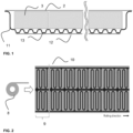
- Figure 1 illustrates the set-up of such a cooling system.
- the battery modules being located inside the shell and covered from the environmental by using a closing plate joined together with the deep-drawn shell.
- the cooling system of the present invention is preferably positioned with the battery compartment on its largest side to enable the best cooling behavior, in most cases represented by the bottom or upper side of the compartment. To enable easier access during repair or replacement situations, the positioning of the cooling system is preferably at the bottom side of the compartment.
- the cooling system in the case of the present invention comprises at least one inlet manifold, a number of outlet manifolds which is equal to the number of inlet manifolds plus one, and individual partial circuits for every battery module area, which circuits are connected with one inlet and one outlet manifold.
- a battery module area is defined in the method of the present invention as the contact area where the battery modules are located inside the battery compartment.
- the inlet manifold is preferably located in the centre of the battery module array. From this inlet manifold, individual partial circuits for every battery module area are branched off and lead to outlet manifolds which are preferably located on the lateral outside.
- Every partial circuit of a battery module area is connected to one inlet manifold and one outlet manifold. Further, the partial circuits are preferably arranged as a meandering design to enable effective cooling of the battery module area, pointed out in figures 2 , 3 , 6 , 7 .
- the term of sinuosity well-known e.g. from rivers, can be used to define an amount for the intensity of meandering of the flowing system. It is illustrated in fig. 6 .
- the sinuosity for the partial circuits should have a value P ⁇ 6.
- a flowing fluid is used and is preferably water, ideally with defroster additives, a coolant or a refrigerant.
- One preferred cooling medium is a water-glycol mixture.
- stainless steels are used to fulfil the method of the present invention because of their corrosion, heat and acid resistance, high formability in general and high deep-drawn-ability, high recyclability and worldwide availability as flat sheets combined with the experience from deep-drawing applications like kitchen sinks over decades.
- the thickness of the flat metallic sheets is t ⁇ 3.0mm, more preferably 0.4mm ⁇ t ⁇ 1.5mm to provide a tight but lightweight and cost-efficient cooling system construction.
- an austenitic stainless steel having a natural and repassivating corrosion resistance because of its chromium-oxide passivation layer and having an elongation of A 80 ⁇ 50% to enable the forming of the cooling system with the mentioned distances and radii.
- the mentioned joining process for creating the channels is prepared by bonding to seal the channels and avoid leakage of the cooling fluid.
- the bonding could be performed with well-known adhesives like cold-curing two-component adhesives (2k) or hot curing single component adhesives (1k).
- 2k cold-curing two-component adhesives
- 1k hot curing single component adhesives
- the functionality of the battery compartment is independent from the mounting position within the electric drive vehicle.
- the battery compartment is located over the whole underbody to ensure a maximum battery range, a low centre of gravity and balanced driving dynamics. Localized constructions like one-side compartments, front or rear-positioning will also work. In these cases, the dimensions of the cooling system of the present invention can be adjusted for different forms or required package solutions.
- the method of the present invention is applicable to various mobile systems or transportation systems using battery modules located in a battery compartment.
- the present invention also works for other types of electric passenger or goods transport systems like electric buses, electric commercial vehicles, electric taxis or vehicles for parcel delivery. It is appropriate to use one battery compartment for one vehicle. But especially for long haul transportation like goods transport with trucks as one example, various battery compartments can be integrated into the vehicle to increase the range. Another reason to create different compartments with different supporting housings could be the limitation of the available coil and plate width or the maximum dimension of the tooling for the shell.
- the cooling system of the present invention can be integrated as a plural solution for every compartment but also as one single solution.
- the cooling effect of the present invention works independently from the type of the used accumulator inside, such as nickel-cadmium, nickel-metal hydride, lithium ion or lithium air batteries.
- Fig. 1 illustrates a battery compartment designed as a deep-drawn shell 11 with a closing plate 2 where the battery modules 3 are located inside.
- the cooling system is directly integrated during deep-drawing of the shell.
- An additional flat closing plate 12 is attached to the bottom side of the shell whereby a space 13 between the formed floor of the battery compartment 11 and the additional closing plate system 12 is created and represents the cooling circuit.
- Fig. 2 illustrates the manufacturing of the cooling system implemented by continuous cold-rolling of a flat coil 8 or strips, whereby repetitive parts 9 of the cooling system are continuously rolled in in the rolling direction of the coil so that a cutting to length 10 can be executed after at least one repetitive part 9.
- Fig. 3 illustrates the cooling system of figure 1 in a top view, whereby the dotted lines represent the battery module area 4 where the battery modules are located on the floor of the battery compartment.
- the centre of the battery modules is located one manifold for the inlet 5, from which manifold individual partial circuits 6 for every battery module area are branched off and lead to, in this case, two outlet manifolds 7. Accordingly, this satisfies the design rule that the number of manifolds for the outlet must be equal to the number of inlet manifolds plus one. Every partial circuit of a battery module area is connected to one inlet manifold and one outlet manifold.
- Fig. 4 illustrates a detail of fig. 1 , whereby a defined distance 14 between the radii of the cooling channels and the bending radius of the battery compartment is arranged. Further, a defined radius 15 for the partial cooling circuits is required to enable on the one hand a sufficient formability of the radii and on the other hand a suitable flow of the cooling liquid.
- Fig. 5 illustrates a detailed view of fig. 3 whereby the pipe bends of the partial circuit 16 are having in their outside as well as their inner side an enlarged radius in the crossflow direction at the upstream end of the bends.
- Fig. 6 illustrates the definition of sinuosity P of an individual partial circuit whereby sinuosity is a measure of the intensity of meandering of the flowing system and defined as the total length of the partial circuit 16 divided by the direct distance between starting point and end point of the partial circuit 17.
- Fig. 7 illustrates another preferred embodiment of the cooling system using the manufacturing method of the present invention so that the number of outlet manifolds 7, in this figure 2 , is equal to the number of inlet manifolds 5, in this figure 3 , plus one. Every partial circuit of a battery module area is connected to one inlet manifold and one outlet manifold.
Landscapes
- Engineering & Computer Science (AREA)
- Chemical & Material Sciences (AREA)
- Mechanical Engineering (AREA)
- Chemical Kinetics & Catalysis (AREA)
- Electrochemistry (AREA)
- General Chemical & Material Sciences (AREA)
- General Engineering & Computer Science (AREA)
- Physics & Mathematics (AREA)
- Thermal Sciences (AREA)
- Manufacturing & Machinery (AREA)
- Sustainable Energy (AREA)
- Power Engineering (AREA)
- Transportation (AREA)
- Sustainable Development (AREA)
- Life Sciences & Earth Sciences (AREA)
- Aviation & Aerospace Engineering (AREA)
- Combustion & Propulsion (AREA)
- Secondary Cells (AREA)
- Battery Mounting, Suspending (AREA)
Priority Applications (8)
| Application Number | Priority Date | Filing Date | Title |
|---|---|---|---|
| PL19180751.0T PL3754279T3 (pl) | 2019-06-18 | 2019-06-18 | System chłodzenia |
| EP19180751.0A EP3754279B1 (en) | 2019-06-18 | 2019-06-18 | Cooling system |
| HUE19180751A HUE064840T2 (hu) | 2019-06-18 | 2019-06-18 | Hûtõrendszer |
| ES19180751T ES2965762T3 (es) | 2019-06-18 | 2019-06-18 | Sistema de refrigeración |
| US17/620,341 US12181231B2 (en) | 2019-06-18 | 2020-06-12 | Cooling system |
| MX2021015231A MX2021015231A (es) | 2019-06-18 | 2020-06-12 | Sistema de enfriamiento. |
| KR1020217040973A KR102932633B1 (ko) | 2019-06-18 | 2020-06-12 | 냉각 시스템 |
| PCT/EP2020/066406 WO2020254214A1 (en) | 2019-06-18 | 2020-06-12 | Cooling system |
Applications Claiming Priority (1)
| Application Number | Priority Date | Filing Date | Title |
|---|---|---|---|
| EP19180751.0A EP3754279B1 (en) | 2019-06-18 | 2019-06-18 | Cooling system |
Publications (2)
| Publication Number | Publication Date |
|---|---|
| EP3754279A1 EP3754279A1 (en) | 2020-12-23 |
| EP3754279B1 true EP3754279B1 (en) | 2023-10-18 |
Family
ID=66951854
Family Applications (1)
| Application Number | Title | Priority Date | Filing Date |
|---|---|---|---|
| EP19180751.0A Active EP3754279B1 (en) | 2019-06-18 | 2019-06-18 | Cooling system |
Country Status (8)
| Country | Link |
|---|---|
| US (1) | US12181231B2 (pl) |
| EP (1) | EP3754279B1 (pl) |
| KR (1) | KR102932633B1 (pl) |
| ES (1) | ES2965762T3 (pl) |
| HU (1) | HUE064840T2 (pl) |
| MX (1) | MX2021015231A (pl) |
| PL (1) | PL3754279T3 (pl) |
| WO (1) | WO2020254214A1 (pl) |
Families Citing this family (5)
| Publication number | Priority date | Publication date | Assignee | Title |
|---|---|---|---|---|
| CN113178639B (zh) * | 2021-04-27 | 2022-12-20 | 北京理工大学重庆创新中心 | 分形网络流道冷却板 |
| DE102021124066B3 (de) | 2021-09-17 | 2022-11-17 | Dr. Ing. H.C. F. Porsche Aktiengesellschaft | Batterieanordnung |
| CN217182329U (zh) * | 2022-03-03 | 2022-08-12 | 宁德时代新能源科技股份有限公司 | 箱体结构、电池及用电装置 |
| FR3136596A1 (fr) * | 2022-06-08 | 2023-12-15 | Valeo Systemes Thermiques | Compartiment pour recevoir un composant susceptible de dégager de la chaleur |
| DE102023117870A1 (de) | 2023-07-06 | 2025-01-09 | Dr. Ing. H.C. F. Porsche Aktiengesellschaft | Batteriemodul, Batterieanordnung und batterieelektrisches Fahrzeug |
Family Cites Families (26)
| Publication number | Priority date | Publication date | Assignee | Title |
|---|---|---|---|---|
| US3623511A (en) * | 1970-02-16 | 1971-11-30 | Bvs | Tubular conduits having a bent portion and carrying a fluid |
| WO1990001659A1 (en) * | 1988-08-15 | 1990-02-22 | Siddons Ramset Limited | Evaporator plate |
| US5084033A (en) * | 1990-03-12 | 1992-01-28 | Minnesota Mining And Manufacturing Company | Arterial cannula tip and method of manufacture |
| US5644842A (en) * | 1995-01-05 | 1997-07-08 | Coleman; Rick L. | Method of making profiled tube and shell heat exchangers |
| JP2005274120A (ja) | 2004-02-24 | 2005-10-06 | Showa Denko Kk | 液冷式冷却板 |
| JP2006118785A (ja) * | 2004-10-21 | 2006-05-11 | Usui Kokusai Sangyo Kaisha Ltd | 熱交換器 |
| WO2007009713A1 (de) * | 2005-07-19 | 2007-01-25 | Behr Gmbh & Co. Kg | Wärmeübertrager |
| US20070221365A1 (en) * | 2006-03-24 | 2007-09-27 | Evapco, Inc. | U-shaped heat exchanger tube with a concavity formed into its return bend |
| US8758924B2 (en) | 2007-06-18 | 2014-06-24 | Tesla Motors, Inc. | Extruded and ribbed thermal interface for use with a battery cooling system |
| DE102007058458B4 (de) * | 2007-12-04 | 2010-08-26 | Adc Gmbh | Doppelwandiges Gehäuse mit wärmeabführenden Funktionsraumwänden |
| WO2009127063A1 (en) * | 2008-04-17 | 2009-10-22 | Dana Canada Corporation | U-flow heat exchanger |
| DE102008059947A1 (de) | 2008-12-02 | 2010-06-10 | Daimler Ag | Batterie mit einer in einem Batteriegehäuse angeordneten Wärmeleitplatte und daran direkt montierten elektronischen Bauelementen zum Temperieren der Batterie |
| US8383260B2 (en) * | 2010-02-26 | 2013-02-26 | GM Global Technology Operations LLC | U-formed cooling plate with solid fins for lithium pouch cells |
| US9291405B2 (en) * | 2011-08-02 | 2016-03-22 | Ford Global Technologies, Llc | Battery pack liquid channel and coldplate cooling system |
| DE102012005871A1 (de) * | 2012-03-23 | 2013-09-26 | Valeo Klimasysteme Gmbh | Kühlvorrichtung für eine Fahrzeugbatterie sowie Fahrzeugbatterie mit Kühlvorrichtung |
| DE102012012663A1 (de) | 2012-06-23 | 2013-12-24 | Volkswagen Aktiengesellschaft | Gehäuse für eine Betriebseinrichtung, insbesondere für ein Batteriepaket einer Fahrzeugantriebsbatterie |
| FR2999695A1 (fr) * | 2012-12-18 | 2014-06-20 | Valeo Systemes Thermiques | Tube plat pour echangeur de chaleur d'air de suralimentation et echangeur de chaleur d'air de suralimentation correspondant. |
| US9437905B2 (en) | 2014-02-25 | 2016-09-06 | Ford Global Technologies, Llc | Traction battery thermal plate manifold |
| WO2015196301A1 (en) * | 2014-06-27 | 2015-12-30 | Dana Canada Corporation | Multi-sided heat exchangers with compliant heat transfer surfaces |
| CN107076532B (zh) * | 2014-07-21 | 2019-06-25 | 达纳加拿大公司 | 带有流动阻碍件以减小流体死区的热交换器 |
| DE102014225971A1 (de) | 2014-12-16 | 2016-06-16 | Robert Bosch Gmbh | Kühlplatte für Batteriezelle als Montageplatte |
| CA2987962A1 (en) * | 2015-06-04 | 2016-12-08 | Dana Canada Corporation | Heat exchanger with regional flow distribution for uniform cooling of battery cells |
| US10622687B2 (en) | 2015-08-10 | 2020-04-14 | Ford Global Technologies, Llc | Battery pack enclosure including integrated fluid channel |
| DE102015217810A1 (de) | 2015-09-17 | 2017-03-23 | Volkswagen Aktiengesellschaft | Gehäuse für eine Batterie, Verfahren zur Herstellung besagten Gehäuses sowie Fahrzeug |
| DE102016114216A1 (de) * | 2016-08-01 | 2018-02-01 | Kirchhoff Automotive Deutschland Gmbh | Temperiereinrichtung für ein Batteriegehäuse eines Fahrzeuges |
| DE102016115627A1 (de) | 2016-08-23 | 2018-03-01 | Benteler Automobiltechnik Gmbh | Batterieträger mit Kühlsystem |
-
2019
- 2019-06-18 PL PL19180751.0T patent/PL3754279T3/pl unknown
- 2019-06-18 ES ES19180751T patent/ES2965762T3/es active Active
- 2019-06-18 EP EP19180751.0A patent/EP3754279B1/en active Active
- 2019-06-18 HU HUE19180751A patent/HUE064840T2/hu unknown
-
2020
- 2020-06-12 WO PCT/EP2020/066406 patent/WO2020254214A1/en not_active Ceased
- 2020-06-12 MX MX2021015231A patent/MX2021015231A/es unknown
- 2020-06-12 KR KR1020217040973A patent/KR102932633B1/ko active Active
- 2020-06-12 US US17/620,341 patent/US12181231B2/en active Active
Also Published As
| Publication number | Publication date |
|---|---|
| PL3754279T3 (pl) | 2024-04-02 |
| WO2020254214A1 (en) | 2020-12-24 |
| US12181231B2 (en) | 2024-12-31 |
| HUE064840T2 (hu) | 2024-04-28 |
| MX2021015231A (es) | 2022-01-18 |
| KR20220024043A (ko) | 2022-03-03 |
| ES2965762T3 (es) | 2024-04-16 |
| US20220316818A1 (en) | 2022-10-06 |
| KR102932633B1 (ko) | 2026-03-03 |
| EP3754279A1 (en) | 2020-12-23 |
Similar Documents
| Publication | Publication Date | Title |
|---|---|---|
| US12181231B2 (en) | Cooling system | |
| US11870048B2 (en) | Thermal systems for battery electric vehicles | |
| EP3636364B1 (en) | Method for manufacturing a crash frame of a battery compartment for battery electric vehicles | |
| EP2810336B1 (en) | Method for cooling a lithium-ion battery pack | |
| US20160372805A1 (en) | Battery pack | |
| US8430151B2 (en) | Integrated hybrid heat exchanger using water head difference | |
| TWI897864B (zh) | 冷卻系統及其製造方法和用途 | |
| EP4604271A1 (en) | Cooling floor member and method for manufacturing cooling floor member | |
| US20260091707A1 (en) | Cold plates for liquid cooling systems, methods for use thereof, and vehicles including the same | |
| CN118431608A (zh) | 具有集成冷却系统的电池组 | |
| CN113594579A (zh) | 电池包液冷板及其制造方法、电池包 | |
| Lindner | Stainless Steel in Traction Battery Housings | |
| Lindner | Increased safety for battery electric vehicles by using heat-resistance stainless steels | |
| WO2024157535A1 (ja) | 車両用熱交換器 | |
| WO2026068597A1 (en) | Method for laser welding | |
| JP2022162838A (ja) | 冷却床部材 |
Legal Events
| Date | Code | Title | Description |
|---|---|---|---|
| PUAI | Public reference made under article 153(3) epc to a published international application that has entered the european phase |
Free format text: ORIGINAL CODE: 0009012 |
|
| STAA | Information on the status of an ep patent application or granted ep patent |
Free format text: STATUS: THE APPLICATION HAS BEEN PUBLISHED |
|
| AK | Designated contracting states |
Kind code of ref document: A1 Designated state(s): AL AT BE BG CH CY CZ DE DK EE ES FI FR GB GR HR HU IE IS IT LI LT LU LV MC MK MT NL NO PL PT RO RS SE SI SK SM TR |
|
| AX | Request for extension of the european patent |
Extension state: BA ME |
|
| STAA | Information on the status of an ep patent application or granted ep patent |
Free format text: STATUS: REQUEST FOR EXAMINATION WAS MADE |
|
| 17P | Request for examination filed |
Effective date: 20210623 |
|
| RBV | Designated contracting states (corrected) |
Designated state(s): AL AT BE BG CH CY CZ DE DK EE ES FI FR GB GR HR HU IE IS IT LI LT LU LV MC MK MT NL NO PL PT RO RS SE SI SK SM TR |
|
| STAA | Information on the status of an ep patent application or granted ep patent |
Free format text: STATUS: EXAMINATION IS IN PROGRESS |
|
| 17Q | First examination report despatched |
Effective date: 20220623 |
|
| RIC1 | Information provided on ipc code assigned before grant |
Ipc: F02F 7/00 20060101ALN20221221BHEP Ipc: F28D 21/00 20060101ALN20221221BHEP Ipc: F01M 5/00 20060101ALI20221221BHEP Ipc: H01M 10/6556 20140101ALI20221221BHEP Ipc: H01M 10/625 20140101ALI20221221BHEP Ipc: F28F 3/12 20060101ALI20221221BHEP Ipc: F28D 1/06 20060101ALI20221221BHEP Ipc: F28D 1/03 20060101AFI20221221BHEP |
|
| GRAP | Despatch of communication of intention to grant a patent |
Free format text: ORIGINAL CODE: EPIDOSNIGR1 |
|
| STAA | Information on the status of an ep patent application or granted ep patent |
Free format text: STATUS: GRANT OF PATENT IS INTENDED |
|
| RIC1 | Information provided on ipc code assigned before grant |
Ipc: F02F 7/00 20060101ALN20230116BHEP Ipc: F28D 21/00 20060101ALN20230116BHEP Ipc: F01M 5/00 20060101ALI20230116BHEP Ipc: H01M 10/6556 20140101ALI20230116BHEP Ipc: H01M 10/625 20140101ALI20230116BHEP Ipc: F28F 3/12 20060101ALI20230116BHEP Ipc: F28D 1/06 20060101ALI20230116BHEP Ipc: F28D 1/03 20060101AFI20230116BHEP |
|
| INTG | Intention to grant announced |
Effective date: 20230201 |
|
| GRAS | Grant fee paid |
Free format text: ORIGINAL CODE: EPIDOSNIGR3 |
|
| GRAA | (expected) grant |
Free format text: ORIGINAL CODE: 0009210 |
|
| STAA | Information on the status of an ep patent application or granted ep patent |
Free format text: STATUS: THE PATENT HAS BEEN GRANTED |
|
| AK | Designated contracting states |
Kind code of ref document: B1 Designated state(s): AL AT BE BG CH CY CZ DE DK EE ES FI FR GB GR HR HU IE IS IT LI LT LU LV MC MK MT NL NO PL PT RO RS SE SI SK SM TR |
|
| REG | Reference to a national code |
Ref country code: GB Ref legal event code: FG4D |
|
| REG | Reference to a national code |
Ref country code: CH Ref legal event code: EP |
|
| REG | Reference to a national code |
Ref country code: IE Ref legal event code: FG4D |
|
| REG | Reference to a national code |
Ref country code: DE Ref legal event code: R096 Ref document number: 602019039467 Country of ref document: DE |
|
| REG | Reference to a national code |
Ref country code: LT Ref legal event code: MG9D |
|
| REG | Reference to a national code |
Ref country code: SK Ref legal event code: T3 Ref document number: E 43075 Country of ref document: SK |
|
| REG | Reference to a national code |
Ref country code: NL Ref legal event code: MP Effective date: 20231018 |
|
| PG25 | Lapsed in a contracting state [announced via postgrant information from national office to epo] |
Ref country code: NL Free format text: LAPSE BECAUSE OF FAILURE TO SUBMIT A TRANSLATION OF THE DESCRIPTION OR TO PAY THE FEE WITHIN THE PRESCRIBED TIME-LIMIT Effective date: 20231018 |
|
| PG25 | Lapsed in a contracting state [announced via postgrant information from national office to epo] |
Ref country code: GR Free format text: LAPSE BECAUSE OF FAILURE TO SUBMIT A TRANSLATION OF THE DESCRIPTION OR TO PAY THE FEE WITHIN THE PRESCRIBED TIME-LIMIT Effective date: 20240119 |
|
| PG25 | Lapsed in a contracting state [announced via postgrant information from national office to epo] |
Ref country code: IS Free format text: LAPSE BECAUSE OF FAILURE TO SUBMIT A TRANSLATION OF THE DESCRIPTION OR TO PAY THE FEE WITHIN THE PRESCRIBED TIME-LIMIT Effective date: 20240218 |
|
| PG25 | Lapsed in a contracting state [announced via postgrant information from national office to epo] |
Ref country code: LT Free format text: LAPSE BECAUSE OF FAILURE TO SUBMIT A TRANSLATION OF THE DESCRIPTION OR TO PAY THE FEE WITHIN THE PRESCRIBED TIME-LIMIT Effective date: 20231018 |
|
| REG | Reference to a national code |
Ref country code: AT Ref legal event code: UEP Ref document number: 1622804 Country of ref document: AT Kind code of ref document: T Effective date: 20231018 |
|
| REG | Reference to a national code |
Ref country code: ES Ref legal event code: FG2A Ref document number: 2965762 Country of ref document: ES Kind code of ref document: T3 Effective date: 20240416 |
|
| REG | Reference to a national code |
Ref country code: HU Ref legal event code: AG4A Ref document number: E064840 Country of ref document: HU |
|
| PG25 | Lapsed in a contracting state [announced via postgrant information from national office to epo] |
Ref country code: LT Free format text: LAPSE BECAUSE OF FAILURE TO SUBMIT A TRANSLATION OF THE DESCRIPTION OR TO PAY THE FEE WITHIN THE PRESCRIBED TIME-LIMIT Effective date: 20231018 Ref country code: IS Free format text: LAPSE BECAUSE OF FAILURE TO SUBMIT A TRANSLATION OF THE DESCRIPTION OR TO PAY THE FEE WITHIN THE PRESCRIBED TIME-LIMIT Effective date: 20240218 Ref country code: GR Free format text: LAPSE BECAUSE OF FAILURE TO SUBMIT A TRANSLATION OF THE DESCRIPTION OR TO PAY THE FEE WITHIN THE PRESCRIBED TIME-LIMIT Effective date: 20240119 Ref country code: BG Free format text: LAPSE BECAUSE OF FAILURE TO SUBMIT A TRANSLATION OF THE DESCRIPTION OR TO PAY THE FEE WITHIN THE PRESCRIBED TIME-LIMIT Effective date: 20240118 Ref country code: PT Free format text: LAPSE BECAUSE OF FAILURE TO SUBMIT A TRANSLATION OF THE DESCRIPTION OR TO PAY THE FEE WITHIN THE PRESCRIBED TIME-LIMIT Effective date: 20240219 |
|
| PG25 | Lapsed in a contracting state [announced via postgrant information from national office to epo] |
Ref country code: SE Free format text: LAPSE BECAUSE OF FAILURE TO SUBMIT A TRANSLATION OF THE DESCRIPTION OR TO PAY THE FEE WITHIN THE PRESCRIBED TIME-LIMIT Effective date: 20231018 Ref country code: RS Free format text: LAPSE BECAUSE OF FAILURE TO SUBMIT A TRANSLATION OF THE DESCRIPTION OR TO PAY THE FEE WITHIN THE PRESCRIBED TIME-LIMIT Effective date: 20231018 Ref country code: NO Free format text: LAPSE BECAUSE OF FAILURE TO SUBMIT A TRANSLATION OF THE DESCRIPTION OR TO PAY THE FEE WITHIN THE PRESCRIBED TIME-LIMIT Effective date: 20240118 Ref country code: LV Free format text: LAPSE BECAUSE OF FAILURE TO SUBMIT A TRANSLATION OF THE DESCRIPTION OR TO PAY THE FEE WITHIN THE PRESCRIBED TIME-LIMIT Effective date: 20231018 Ref country code: HR Free format text: LAPSE BECAUSE OF FAILURE TO SUBMIT A TRANSLATION OF THE DESCRIPTION OR TO PAY THE FEE WITHIN THE PRESCRIBED TIME-LIMIT Effective date: 20231018 |
|
| PG25 | Lapsed in a contracting state [announced via postgrant information from national office to epo] |
Ref country code: DK Free format text: LAPSE BECAUSE OF FAILURE TO SUBMIT A TRANSLATION OF THE DESCRIPTION OR TO PAY THE FEE WITHIN THE PRESCRIBED TIME-LIMIT Effective date: 20231018 |
|
| REG | Reference to a national code |
Ref country code: DE Ref legal event code: R097 Ref document number: 602019039467 Country of ref document: DE |
|
| PG25 | Lapsed in a contracting state [announced via postgrant information from national office to epo] |
Ref country code: SM Free format text: LAPSE BECAUSE OF FAILURE TO SUBMIT A TRANSLATION OF THE DESCRIPTION OR TO PAY THE FEE WITHIN THE PRESCRIBED TIME-LIMIT Effective date: 20231018 Ref country code: RO Free format text: LAPSE BECAUSE OF FAILURE TO SUBMIT A TRANSLATION OF THE DESCRIPTION OR TO PAY THE FEE WITHIN THE PRESCRIBED TIME-LIMIT Effective date: 20231018 Ref country code: EE Free format text: LAPSE BECAUSE OF FAILURE TO SUBMIT A TRANSLATION OF THE DESCRIPTION OR TO PAY THE FEE WITHIN THE PRESCRIBED TIME-LIMIT Effective date: 20231018 Ref country code: DK Free format text: LAPSE BECAUSE OF FAILURE TO SUBMIT A TRANSLATION OF THE DESCRIPTION OR TO PAY THE FEE WITHIN THE PRESCRIBED TIME-LIMIT Effective date: 20231018 |
|
| PLBE | No opposition filed within time limit |
Free format text: ORIGINAL CODE: 0009261 |
|
| STAA | Information on the status of an ep patent application or granted ep patent |
Free format text: STATUS: NO OPPOSITION FILED WITHIN TIME LIMIT |
|
| 26N | No opposition filed |
Effective date: 20240719 |
|
| PG25 | Lapsed in a contracting state [announced via postgrant information from national office to epo] |
Ref country code: SI Free format text: LAPSE BECAUSE OF FAILURE TO SUBMIT A TRANSLATION OF THE DESCRIPTION OR TO PAY THE FEE WITHIN THE PRESCRIBED TIME-LIMIT Effective date: 20231018 |
|
| PG25 | Lapsed in a contracting state [announced via postgrant information from national office to epo] |
Ref country code: SI Free format text: LAPSE BECAUSE OF FAILURE TO SUBMIT A TRANSLATION OF THE DESCRIPTION OR TO PAY THE FEE WITHIN THE PRESCRIBED TIME-LIMIT Effective date: 20231018 |
|
| PG25 | Lapsed in a contracting state [announced via postgrant information from national office to epo] |
Ref country code: MC Free format text: LAPSE BECAUSE OF FAILURE TO SUBMIT A TRANSLATION OF THE DESCRIPTION OR TO PAY THE FEE WITHIN THE PRESCRIBED TIME-LIMIT Effective date: 20231018 |
|
| REG | Reference to a national code |
Ref country code: CH Ref legal event code: PL |
|
| PG25 | Lapsed in a contracting state [announced via postgrant information from national office to epo] |
Ref country code: LU Free format text: LAPSE BECAUSE OF NON-PAYMENT OF DUE FEES Effective date: 20240618 |
|
| PG25 | Lapsed in a contracting state [announced via postgrant information from national office to epo] |
Ref country code: IE Free format text: LAPSE BECAUSE OF NON-PAYMENT OF DUE FEES Effective date: 20240618 |
|
| PG25 | Lapsed in a contracting state [announced via postgrant information from national office to epo] |
Ref country code: BE Free format text: LAPSE BECAUSE OF NON-PAYMENT OF DUE FEES Effective date: 20240630 Ref country code: CH Free format text: LAPSE BECAUSE OF NON-PAYMENT OF DUE FEES Effective date: 20240630 |
|
| REG | Reference to a national code |
Ref country code: BE Ref legal event code: MM Effective date: 20240630 |
|
| PGFP | Annual fee paid to national office [announced via postgrant information from national office to epo] |
Ref country code: DE Payment date: 20250618 Year of fee payment: 7 Ref country code: PL Payment date: 20250606 Year of fee payment: 7 |
|
| PGFP | Annual fee paid to national office [announced via postgrant information from national office to epo] |
Ref country code: GB Payment date: 20250618 Year of fee payment: 7 |
|
| PGFP | Annual fee paid to national office [announced via postgrant information from national office to epo] |
Ref country code: HU Payment date: 20250620 Year of fee payment: 7 Ref country code: FR Payment date: 20250626 Year of fee payment: 7 |
|
| PGFP | Annual fee paid to national office [announced via postgrant information from national office to epo] |
Ref country code: AT Payment date: 20250620 Year of fee payment: 7 |
|
| PGFP | Annual fee paid to national office [announced via postgrant information from national office to epo] |
Ref country code: TR Payment date: 20250611 Year of fee payment: 7 Ref country code: SK Payment date: 20250609 Year of fee payment: 7 |
|
| PGFP | Annual fee paid to national office [announced via postgrant information from national office to epo] |
Ref country code: CZ Payment date: 20250610 Year of fee payment: 7 |
|
| PG25 | Lapsed in a contracting state [announced via postgrant information from national office to epo] |
Ref country code: FI Free format text: LAPSE BECAUSE OF FAILURE TO SUBMIT A TRANSLATION OF THE DESCRIPTION OR TO PAY THE FEE WITHIN THE PRESCRIBED TIME-LIMIT Effective date: 20231019 |
|
| PGFP | Annual fee paid to national office [announced via postgrant information from national office to epo] |
Ref country code: ES Payment date: 20250731 Year of fee payment: 7 |
|
| PGFP | Annual fee paid to national office [announced via postgrant information from national office to epo] |
Ref country code: IT Payment date: 20250619 Year of fee payment: 7 |
|
| PG25 | Lapsed in a contracting state [announced via postgrant information from national office to epo] |
Ref country code: CY Free format text: LAPSE BECAUSE OF FAILURE TO SUBMIT A TRANSLATION OF THE DESCRIPTION OR TO PAY THE FEE WITHIN THE PRESCRIBED TIME-LIMIT; INVALID AB INITIO Effective date: 20190618 |