EP3754165A1 - Komponente für eine abgasanlage einer brennkraftmaschine - Google Patents
Komponente für eine abgasanlage einer brennkraftmaschine Download PDFInfo
- Publication number
- EP3754165A1 EP3754165A1 EP20175161.7A EP20175161A EP3754165A1 EP 3754165 A1 EP3754165 A1 EP 3754165A1 EP 20175161 A EP20175161 A EP 20175161A EP 3754165 A1 EP3754165 A1 EP 3754165A1
- Authority
- EP
- European Patent Office
- Prior art keywords
- support rod
- component
- housing
- component according
- fastening
- Prior art date
- Legal status (The legal status is an assumption and is not a legal conclusion. Google has not performed a legal analysis and makes no representation as to the accuracy of the status listed.)
- Granted
Links
Images

Classifications
-
- F—MECHANICAL ENGINEERING; LIGHTING; HEATING; WEAPONS; BLASTING
- F01—MACHINES OR ENGINES IN GENERAL; ENGINE PLANTS IN GENERAL; STEAM ENGINES
- F01N—GAS-FLOW SILENCERS OR EXHAUST APPARATUS FOR MACHINES OR ENGINES IN GENERAL; GAS-FLOW SILENCERS OR EXHAUST APPARATUS FOR INTERNAL-COMBUSTION ENGINES
- F01N1/00—Silencing apparatus characterised by method of silencing
- F01N1/02—Silencing apparatus characterised by method of silencing by using resonance
-
- F—MECHANICAL ENGINEERING; LIGHTING; HEATING; WEAPONS; BLASTING
- F01—MACHINES OR ENGINES IN GENERAL; ENGINE PLANTS IN GENERAL; STEAM ENGINES
- F01N—GAS-FLOW SILENCERS OR EXHAUST APPARATUS FOR MACHINES OR ENGINES IN GENERAL; GAS-FLOW SILENCERS OR EXHAUST APPARATUS FOR INTERNAL-COMBUSTION ENGINES
- F01N13/00—Exhaust or silencing apparatus characterised by constructional features
- F01N13/18—Construction facilitating manufacture, assembly, or disassembly
- F01N13/1805—Fixing exhaust manifolds, exhaust pipes or pipe sections to each other, to engine or to vehicle body
-
- F—MECHANICAL ENGINEERING; LIGHTING; HEATING; WEAPONS; BLASTING
- F01—MACHINES OR ENGINES IN GENERAL; ENGINE PLANTS IN GENERAL; STEAM ENGINES
- F01N—GAS-FLOW SILENCERS OR EXHAUST APPARATUS FOR MACHINES OR ENGINES IN GENERAL; GAS-FLOW SILENCERS OR EXHAUST APPARATUS FOR INTERNAL-COMBUSTION ENGINES
- F01N13/00—Exhaust or silencing apparatus characterised by constructional features
-
- B—PERFORMING OPERATIONS; TRANSPORTING
- B60—VEHICLES IN GENERAL
- B60K—ARRANGEMENT OR MOUNTING OF PROPULSION UNITS OR OF TRANSMISSIONS IN VEHICLES; ARRANGEMENT OR MOUNTING OF PLURAL DIVERSE PRIME-MOVERS IN VEHICLES; AUXILIARY DRIVES FOR VEHICLES; INSTRUMENTATION OR DASHBOARDS FOR VEHICLES; ARRANGEMENTS IN CONNECTION WITH COOLING, AIR INTAKE, GAS EXHAUST OR FUEL SUPPLY OF PROPULSION UNITS IN VEHICLES
- B60K13/00—Arrangement in connection with combustion air intake or gas exhaust of propulsion units
- B60K13/04—Arrangement in connection with combustion air intake or gas exhaust of propulsion units concerning exhaust
-
- F—MECHANICAL ENGINEERING; LIGHTING; HEATING; WEAPONS; BLASTING
- F01—MACHINES OR ENGINES IN GENERAL; ENGINE PLANTS IN GENERAL; STEAM ENGINES
- F01N—GAS-FLOW SILENCERS OR EXHAUST APPARATUS FOR MACHINES OR ENGINES IN GENERAL; GAS-FLOW SILENCERS OR EXHAUST APPARATUS FOR INTERNAL-COMBUSTION ENGINES
- F01N1/00—Silencing apparatus characterised by method of silencing
-
- F—MECHANICAL ENGINEERING; LIGHTING; HEATING; WEAPONS; BLASTING
- F01—MACHINES OR ENGINES IN GENERAL; ENGINE PLANTS IN GENERAL; STEAM ENGINES
- F01N—GAS-FLOW SILENCERS OR EXHAUST APPARATUS FOR MACHINES OR ENGINES IN GENERAL; GAS-FLOW SILENCERS OR EXHAUST APPARATUS FOR INTERNAL-COMBUSTION ENGINES
- F01N13/00—Exhaust or silencing apparatus characterised by constructional features
- F01N13/007—Apparatus used as intake or exhaust silencer
-
- F—MECHANICAL ENGINEERING; LIGHTING; HEATING; WEAPONS; BLASTING
- F01—MACHINES OR ENGINES IN GENERAL; ENGINE PLANTS IN GENERAL; STEAM ENGINES
- F01N—GAS-FLOW SILENCERS OR EXHAUST APPARATUS FOR MACHINES OR ENGINES IN GENERAL; GAS-FLOW SILENCERS OR EXHAUST APPARATUS FOR INTERNAL-COMBUSTION ENGINES
- F01N13/00—Exhaust or silencing apparatus characterised by constructional features
- F01N13/08—Other arrangements or adaptations of exhaust conduits
-
- F—MECHANICAL ENGINEERING; LIGHTING; HEATING; WEAPONS; BLASTING
- F01—MACHINES OR ENGINES IN GENERAL; ENGINE PLANTS IN GENERAL; STEAM ENGINES
- F01N—GAS-FLOW SILENCERS OR EXHAUST APPARATUS FOR MACHINES OR ENGINES IN GENERAL; GAS-FLOW SILENCERS OR EXHAUST APPARATUS FOR INTERNAL-COMBUSTION ENGINES
- F01N13/00—Exhaust or silencing apparatus characterised by constructional features
- F01N13/18—Construction facilitating manufacture, assembly, or disassembly
-
- F—MECHANICAL ENGINEERING; LIGHTING; HEATING; WEAPONS; BLASTING
- F01—MACHINES OR ENGINES IN GENERAL; ENGINE PLANTS IN GENERAL; STEAM ENGINES
- F01N—GAS-FLOW SILENCERS OR EXHAUST APPARATUS FOR MACHINES OR ENGINES IN GENERAL; GAS-FLOW SILENCERS OR EXHAUST APPARATUS FOR INTERNAL-COMBUSTION ENGINES
- F01N13/00—Exhaust or silencing apparatus characterised by constructional features
- F01N13/18—Construction facilitating manufacture, assembly, or disassembly
- F01N13/1805—Fixing exhaust manifolds, exhaust pipes or pipe sections to each other, to engine or to vehicle body
- F01N13/1811—Fixing exhaust manifolds, exhaust pipes or pipe sections to each other, to engine or to vehicle body with means permitting relative movement, e.g. compensation of thermal expansion or vibration
- F01N13/1822—Fixing exhaust manifolds, exhaust pipes or pipe sections to each other, to engine or to vehicle body with means permitting relative movement, e.g. compensation of thermal expansion or vibration for fixing exhaust pipes or devices to vehicle body
-
- F—MECHANICAL ENGINEERING; LIGHTING; HEATING; WEAPONS; BLASTING
- F01—MACHINES OR ENGINES IN GENERAL; ENGINE PLANTS IN GENERAL; STEAM ENGINES
- F01N—GAS-FLOW SILENCERS OR EXHAUST APPARATUS FOR MACHINES OR ENGINES IN GENERAL; GAS-FLOW SILENCERS OR EXHAUST APPARATUS FOR INTERNAL-COMBUSTION ENGINES
- F01N13/00—Exhaust or silencing apparatus characterised by constructional features
- F01N13/18—Construction facilitating manufacture, assembly, or disassembly
- F01N13/1838—Construction facilitating manufacture, assembly, or disassembly characterised by the type of connection between parts of exhaust or silencing apparatus, e.g. between housing and tubes, between tubes and baffles
- F01N13/1844—Mechanical joints
- F01N13/1855—Mechanical joints the connection being realised by using bolts, screws, rivets or the like
Definitions
- the present invention relates to a component for an exhaust system of an internal combustion engine, such as, for example, a rear silencer provided in an end region of such an exhaust system.
- connection areas are provided on such an exhaust system, in which such an exhaust system can be fixed on the underside of a vehicle, in particular in the area of an underbody of the vehicle, generally using connection elements formed with elastic material.
- connection elements formed with elastic material.
- two such connection areas are generally provided in order to ensure a stable connection to a vehicle.
- a component for an exhaust system of an internal combustion engine comprising a component housing elongated in the direction of a housing axis with an exhaust gas inlet and an exhaust gas outlet and a support assembly for connecting the component to a support structure, the support assembly comprising a support rod, the support rod in at least two fastening areas lying at a distance from one another along the support rod is fixed to the component housing and has at least one support rod connection area for connection to the support structure.
- a support rod that is fastened to the component housing of the component in several fastening areas and which, on the other hand, can be connected to a support structure on a vehicle in at least one support rod connection area, a stable mounting is ensured in which the forces acting between the support structure and the component are largely transmitted via the support rod and thus kept away from the component can be.
- the support rod can be made very stable at low manufacturing costs and thus be designed to absorb the forces that occur without the risk of damage.
- the component can be designed in such a way that the component housing comprises a circumferential wall elongated in the direction of the housing axis. Since this peripheral wall generally consists of a single, for example tubular, component, the load acting on the component can then be kept low in that the support rod is fastened to the peripheral wall in at least one fastening area.
- the support rod can advantageously be fastened to the peripheral wall in at least two or all fastening areas.
- fastening areas are as far apart as possible. It is therefore proposed that at least one fastening area is provided in an axial end area of the peripheral wall. Such a fastening area, which establishes a fixed connection with the support rod, can preferably be provided in each axial end area of the circumferential wall.
- At least one, preferably each fastening area can comprise a fastening element attached to the component housing and the support rod.
- the fastening element can be fixed to the component housing and / or the support rod by material bonding, preferably welding.
- the support rod can have two support rod end regions. At least one, preferably each, support rod connection area can then be provided on a support rod end area.
- connection element In order to avoid the transmission of vibrations or shocks between the component and the support structure as far as possible in the area of the support rod connection areas, it is proposed that at least one, preferably each support rod connection area, be at least partially covered with elastic material, such as rubber material, constructed connection element includes.
- the support rod be arranged completely outside the component housing.
- the support rod can be of tubular design.
- the support bar can be designed to extend essentially in a straight line between its support bar connection areas.
- the support rod can be fastened to the component housing in at least two fastening areas arranged at a distance from one another in the direction of the housing longitudinal axis. Furthermore, in its length region interacting with the fastening regions, the support rod can be arranged so as to extend essentially in the direction of the longitudinal axis of the housing and / or be designed to extend essentially in a straight line.
- the exhaust gas inlet can comprise at least one inlet pipe which is preferably connected to an end wall of the component housing.
- the exhaust outlet can have at least one preferably connected to an end wall of the component housing, for example an outlet pipe providing an end pipe.
- the component can be a silencer, preferably a rear silencer.
- the invention also relates to an exhaust system for an internal combustion engine, in particular in a motor vehicle, comprising a component constructed according to the invention.
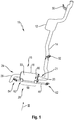
- an exhaust system for an internal combustion engine in a vehicle is generally designated 10.
- the exhaust system 10 includes an exhaust gas treatment unit 12 to be connected to an internal combustion engine, for example via an exhaust manifold (not shown).
- This can include, for example, a catalytic converter, a particle filter, a main silencer or the like.
- An exhaust pipe 14 following the exhaust gas treatment unit 12 leads to a component 16 of the exhaust system 10, which is designed as a rear muffler 18 in the example shown.
- an end region of the exhaust pipe 14 that provides an inlet pipe 20 of an exhaust gas inlet 21 opens into a component housing 22 of the component 16 or of the rear silencer 18.
- An outlet pipe 26 providing an exhaust gas outlet 24 in the form of a tail pipe leads out of the component housing 22.
- the exhaust system 10 can be connected to or suspended from a support structure in a vehicle, for example in the area of an underbody, upstream or also downstream of the exhaust gas treatment unit 12 via connection areas 30, 32.
- a support assembly 28 is provided, by means of which the component 16 can be fixed or suspended from the support structure.
- the component housing 22 comprises, for example, a cylindrical circumferential wall 36 which is elongated in the direction of a housing longitudinal axis A. At both axial end regions 38, 40 of the circumferential wall 36, end walls 42, 44 are provided that are firmly connected to the circumferential wall 36 by a form fit and / or material fit.
- the inlet pipe 20 is connected to the end wall 42.
- the outlet pipe 26 is connected to the end wall 44.
- the carrier assembly 28 provided for connecting the component 16 to a carrier structure of a vehicle comprises a carrier rod 46, for example made of metal material, which is embodied as a tube, that is to say in the manner of a tube and extends completely outside the component housing 22.
- a carrier rod 46 for example made of metal material, which is embodied as a tube, that is to say in the manner of a tube and extends completely outside the component housing 22.
- This is designed to extend essentially in a straight line between its support rod end regions 48, 50 and provides a support rod connection region 52, 54 in each of its end regions 48, 50.
- the support rod 46 can be bent over in the two support rod end regions 48, 50 and in the bent over Areas can be connected to respective connecting elements 56, 58.
- These connection elements 56, 58 can be connected to the support rod 46, for example by screwing and / or material connection, and covered with elastic material, such as. B. rubber material, have built-up transmission elements.
- These connection elements 56, 58 can be
- the support rod 46 is fastened to the component housing 22 in two fastening regions 60, 62 arranged at a distance from one another in the direction of the housing axis A, in particular in the end regions 38, 40 of the component housing 22 and the peripheral wall 36.
- Each of the fastening areas 60, 62 can comprise a fastening element 64 or 66, designed for example as a tab, preferably fixed by welding on the outside of the peripheral wall 36 of the component housing 22, which can also be fixed on the support rod 46 by welding.
- the support rod 46 extends essentially in the direction of the housing axis A and, as in its length sections also outside the length region 68, is essentially straight formed extending.
- connection of an exhaust system 10 formed with such a component 16 to the support structure of a vehicle takes place in the area of the two connection areas 52, 54 of the support rod 46.
- This ensures a comparatively large distance between the connection areas 52, 54 providing the connection to the support structure, which is clearly evident is or can be greater than the distance between the fastening areas 60, 62 acting between the support rod 46 and the component housing 42.
- the two fastening areas 60, 62 are also at a comparatively large distance from one another, since they are each in the end areas 38, 40 of the Component housing 22 act, that is to say to a respective axial end, for example the circumferential wall 36 or the one on it fixed end walls 42, 44 have a smaller distance than from the axial central region of the peripheral wall 36.
- the carrier assembly 28 shown here ensures a stable connection to a vehicle, which is provided with a comparatively small number of components and which is comparatively less stressful for the component 16.
- a component constructed according to the invention or the carrier assembly 28 provided for it could also be configured differently than shown.
- the component housing 22, unlike in FIG Fig. 2 not be designed as separate components with a circumferential wall and end walls provided at the two end regions thereof, but rather, as in FIG Fig. 1 shown in connection with the exhaust gas treatment unit 12, with two half-shells, each of which provides a part of a peripheral wall and a part of the two end walls.
- More than two fastening areas 60, 62 could be provided, and the support rod 46 could, for example, be designed to be curved in some areas in an area outside the length area 68 for adaptation to the support structure of a vehicle.
Landscapes
- Engineering & Computer Science (AREA)
- Chemical & Material Sciences (AREA)
- Combustion & Propulsion (AREA)
- Mechanical Engineering (AREA)
- General Engineering & Computer Science (AREA)
- Transportation (AREA)
- Exhaust Silencers (AREA)
Abstract
Description
- Die vorliegende Erfindung betrifft eine Komponente für eine Abgasanlage einer Brennkraftmaschine, wie zum Beispiel einen in einem Endbereich einer derartigen Abgasanlage vorgesehenen Nachschalldämpfer.
- Zur Befestigung einer Abgasanlage in einem Fahrzeug sind an einer derartigen Abgasanlage mehrere Anbindungsbereiche vorgesehen, in welchen im Allgemeinen unter Verwendung von mit elastischem Material ausgebildeten Anbindungselementen eine derartige Abgasanlage an der Unterseite eines Fahrzeugs, insbesondere im Bereich eines Unterbodens des Fahrzeugs, festgelegt werden kann. In Zuordnung zu verschiedenen Komponenten, wie zum Beispiel Nachschalldämpfern, sind im Allgemeinen zwei derartige Anbindungsbereiche vorgesehen, um eine stabile Anbindung an ein Fahrzeug zu gewährleisten.
- Es ist die Aufgabe der vorliegenden Erfindung, eine Komponente für eine Abgasanlage einer Brennkraftmaschine vorzusehen, mit welcher eine stabile und eine übermäßige Belastung der Komponente selbst vermeidende Anbindung an ein Fahrzeug erreicht wird.
- Erfindungsgemäß wird diese Aufgabe gelöst durch eine Komponente für eine Abgasanlage einer Brennkraftmaschine, umfassend ein in Richtung einer Gehäuseachse langgestrecktes Komponentengehäuse mit einem Abgaseinlass und einem Abgasauslass und eine Trägerbaugruppe zur Anbindung der Komponente an eine Trägerstruktur, wobei die Trägerbaugruppe einen Trägerstab umfasst, wobei der Trägerstab in wenigstens zwei entlang des Trägerstabs in Abstand zueinander liegenden Befestigungsbereichen an dem Komponentengehäuse festgelegt ist und wenigstens einen Trägerstab-Anbindungsbereich zur Anbindung an die Trägerstruktur aufweist.
- Durch den Einsatz eines Trägerstabs, der einerseits in mehreren Befestigungsbereichen an dem Komponentengehäuse der Komponente befestigt ist und der andererseits in zumindest einem Trägerstab-Anbindungsbereich an eine Trägerstruktur an einem Fahrzeug angebunden werden kann, wird eine stabile Halterung gewährleistet, bei welcher die zwischen der Trägerstruktur und der Komponente wirkenden Kräfte zum großen Teil auch über den Trägerstab übertragen und somit von der Komponente ferngehalten werden können. Der Trägerstab kann bei geringen Fertigungskosten sehr stabil und die auftretenden Kräfte somit ohne die Gefahr einer Beschädigung aufnehmend ausgebildet werden.
- Die Komponente kann derart ausgebildet sein, dass das Komponentengehäuse eine in Richtung der Gehäuseachse langgestreckte Umfangswandung umfasst. Da diese Umfangswandung im Allgemeinen aus einem einzigen, beispielsweise rohrartig ausgebildeten Bauteil besteht, kann die auf die Komponente einwirkende Belastung dann dadurch gering gehalten werden, dass in wenigstens einem Befestigungsbereich der Trägerstab an der Umfangswandung befestigt ist. Vorteilhafterweise kann dabei der Trägerstab in wenigstens zwei bzw. allen Befestigungsbereichen an der Umfangswandung befestigt sein.
- Für eine stabile Anbindung ist es besonders vorteilhaft, wenn die Befestigungsbereiche einen möglichst großen Abstand zueinander aufweisen. Es wird daher vorgeschlagen, dass wenigstens ein Befestigungsbereich in einem axialen Endbereich der Umfangswandung vorgesehen ist. Vorzugsweise kann in jedem axialen Endbereich der Umfangswandung ein derartiger eine feste Verbindung mit dem Trägerstab herstellender Befestigungsbereich vorgesehen sein.
- Für eine stabile Verbindung zwischen dem Trägerstab und dem Komponentengehäuse kann wenigstens ein, vorzugsweise jeder Befestigungsbereich ein an dem Komponentengehäuse und dem Trägerstab festgelegtes Befestigungselement umfassen.
- Weiter kann bei einem einfach und kostengünstig zu realisierenden Aufbau das Befestigungselement an dem Komponentengehäuse oder/und dem Trägerstab durch Materialschluss, vorzugsweise Verschweißen, festgelegt sein.
- Für die stabile Anbindung an eine in einem Fahrzeug vorgesehene Trägerstruktur kann der Trägerstab zwei Trägerstab-Endbereiche aufweisen. Wenigstens ein, vorzugsweise jeder Trägerstab-Anbindungsbereich kann dann an einem Trägerstab-Endbereich vorgesehen sein.
- Um im Bereich der Trägerstab-Anbindungsbereiche die Übertragung von Schwingungen bzw. Stößen zwischen der Komponente und der Trägerstruktur soweit als möglich zu vermeiden, wird vorgeschlagen, dass wenigstens ein, vorzugsweise jeder Trägerstab-Anbindungsbereich ein wenigstens bereichsweise mit elastischem Material, wie zum Beispiel Gummimaterial, aufgebautes Anbindungselement umfasst.
- Zum realisieren eines einfach herzustellenden Aufbaus wird vorgeschlagen, dass der Trägerstab vollständig außerhalb des Komponentengehäuses angeordnet ist.
- Bei einer stabilen, gleichwohl ein geringes Gewicht bereitstellenden Ausgestaltung kann der Trägerstab rohrartig ausgebildet sein.
- Der Trägerstab kann zwischen seinen Trägerstab-Anbindungsbereichen sich im Wesentlichen geradlinig erstreckend ausgebildet sein.
- Für eine das Komponentengehäuse wenig belastende Verbindung kann der Trägerstab in wenigstens zwei in Richtung der Gehäuselängsachse in Abstand zueinander angeordneten Befestigungsbereichen an dem Komponentengehäuse befestigt sein. Weiter kann dabei der Trägerstab in seinem mit den Befestigungsbereichen zusammenwirkenden Längenbereich sich im Wesentlichen in Richtung der Gehäuselängsachse erstreckend angeordnet sein oder/und sich im Wesentlichen geradlinig erstreckend ausgebildet sein.
- Für die Einbindung der Komponente in eine Abgasanlage kann der Abgaseinlass wenigstens ein vorzugsweise an eine Stirnwand des Komponentengehäuses angebundenes Einlassrohr umfassen. Der Abgasauslass kann wenigstens ein vorzugsweise an eine Stirnwand des Komponentengehäuses angebundenes, beispielsweise ein Endrohr bereitstellendes Auslassrohr umfassen.
- Die Komponente kann ein Schalldämpfer, vorzugsweise Nachschalldämpfer, sein.
- Die Erfindung betrifft ferner eine Abgasanlage für eine Brennkraftmaschine, insbesondere in einem Kraftfahrzeug, umfassend eine erfindungsgemäß aufgebaute Komponente.
- Die vorliegende Erfindung wird nachfolgend mit Bezug auf die beiliegenden Figuren detailliert beschrieben. Es zeigt:
- Fig. 1
- eine perspektivische Ansicht einer Abgasanlage für eine Brennkraftmaschine in einem Fahrzeug;
- Fig. 2
- einen Draufsicht auf die Abgasanlage der
Fig. 1 ; - Fig. 3
- eine Ansicht der Abgasanlage der
Fig. 1 in Blickrichtung III inFig. 1 . - In den
Fig. 1-3 ist eine Abgasanlage für eine Brennkraftmaschine in einem Fahrzeug allgemein mit 10 bezeichnet. Die Abgasanlage 10 umfasst in einem stromaufwärtigen Bereich eine beispielsweise über einen nicht dargestellten Auslasskrümmer an eine Brennkraftmaschine anzubindende Abgasbehandlungseinheit 12. Diese kann beispielsweise einen Katalysator, einen Partikelfilter, einen Hauptschalldämpfer oder dergleichen umfassen. Ein auf die Abgasbehandlungseinheit 12 folgendes Abgasrohr 14 führt zu einer Komponente 16 der Abgasanlage 10, welche im dargestellten Beispiel als Nachschalldämpfer 18 ausgebildet ist. Dabei mündet ein ein Einlassrohr 20 eines Abgaseinlasses 21 bereitstellender Endbereich des Abgasrohrs 14 in ein Komponentengehäuse 22 der Komponente 16 bzw. des Nachschalldämpfers 18 ein. Ein einen Abgasauslass 24 in Form eines Endrohrs bereitstellendes Auslassrohr 26 führt aus dem Komponentengehäuse 22 heraus. - Die Abgasanlage 10 kann stromaufwärts bzw. auch stromabwärts der Abgasbehandlungseinheit 12 über Anbindungsbereiche 30, 32 an eine Trägerstruktur in einem Fahrzeug, beispielsweise im Bereich eines Unterbodens, angebunden bzw. daran aufgehängt werden. In Zuordnung zu der als Nachschalldämpfer 18 ausgebildeten Komponente ist eine Trägerbaugruppe 28 vorgesehen, vermittels welcher die Komponente 16 an der Trägerstruktur festgelegt bzw. aufgehängt werden kann.
- Insbesondere im Bereich der Anbindung der Komponente 16 an die Trägerstruktur eines Fahrzeugs werden zwischen der Trägerstruktur und der Komponente 16 bzw. dem Komponentengehäuse 22 wirkende Kräfte zum Erzeugen eines Kraftrückschlusses über das Komponentengehäuse 22 übertragen. Dies kann zu starken Belastungen führen, so dass das Erfordernis besteht, das Komponentengehäuse 22 entsprechend stabil auszugestalten.
- Bei der in den
Fig. 1-3 dargestellten Abgasanlage werden derartige Kräfte von dem Komponentengehäuse 22 weitestgehend ferngehalten. Wie inFig. 2 deutlich erkennbar, umfasst das Komponentengehäuse 22 eine beispielsweise zylindrisch ausgebildete und in Richtung einer Gehäuselängsachse A langgestreckte Umfangswandung 36. An beiden axialen Endbereichen 38, 40 der Umfangswandung 36 sind mit der Umfangswandung 36 durch Formschluss oder/und Materialschluss fest verbundene Stirnwände 42, 44 vorgesehen. An die Stirnwand 42 ist das Einlassrohr 20 angebunden. An die Stirnwand 44 ist das Auslassrohr 26 angebunden. - Die zur Anbindung der Komponente 16 an eine Trägerstruktur eines Fahrzeugs vorgesehene Trägerbaugruppe 28 umfasst einen beispielsweise als Rohr, also rohrartig ausgebildeten, vollständig außerhalb des Komponentengehäuses 22 verlaufenden Trägerstab 46 z.B. aus Metallmaterial. Dieser ist zwischen seinen Trägerstab-Endbereichen 48, 50 sich im Wesentlichen geradlinig erstreckend ausgebildet und stellt in jedem seiner Endbereiche 48, 50 einen Trägerstab-Anbindungsbereich 52, 54 bereit. Beispielsweise kann in den beiden Trägerstab-Endbereichen 48, 50 der Trägerstab 46 umgebogen und in den umgebogenen Bereichen mit jeweiligen Anbindungselementen 56, 58 verbunden sein. Diese Anbindungselemente 56, 58 können beispielsweise durch Verschraubung oder/und Materialschluss an den Trägerstab 46 angebunden sein und mit elastischem Material, wie z. B. Gummimaterial, aufgebaute Übertragungselemente aufweisen. An der Trägerstruktur eines Fahrzeugs können diese Anbindungselemente 56, 58 beispielsweise durch Verschraubung festgelegt werden.
- Der Trägerstab 46 ist im dargestellten Beispiel in zwei in Richtung der Gehäuseachse A in Abstand zueinander angeordneten, insbesondere in den Endbereichen 38, 40 des Komponentengehäuses 22 bzw. der Umfangswandung 36 vorgesehenen Befestigungsbereichen 60, 62 am Komponentengehäuse 22 befestigt sein. Jeder der Befestigungsbereiche 60, 62 kann ein beispielsweise als Lasche ausgebildetes, an der Außenseite der Umfangswandung 36 des Komponentengehäuses 22 vorzugsweise durch Verschweißung festgelegtes Befestigungselement 64 bzw. 66 umfassen, das auch am Trägerstab 46 durch Verschweißung festgelegt sein kann. In seinem zur Befestigung an dem Komponentengehäuse 22 vorgesehenen, mit den Befestigungsbereichen 60, 62 zusammenwirkenden Längenbereich 68 erstreckt der Trägerstab 46 sich im Wesentlichen in Richtung der Gehäuseachse A und ist, so wie in seinen auch außerhalb des Längenbereichs 68 liegenden Längenabschnitten, im Wesentlichen geradlinig sich erstreckend ausgebildet.
- Die Anbindung einer mit einer derartigen Komponente 16 ausgebildeten Abgasanlage 10 an die Trägerstruktur eines Fahrzeugs erfolgt im Bereich der beiden Anbindungsbereiche 52, 54 des Trägerstabs 46. Dadurch wird ein vergleichsweise großer Abstand der die Anbindung an die Trägerstruktur bereitstellenden Anbindungsbereiche 52, 54 gewährleistet, der deutlich größer ist bzw. sein kann, als der Abstand der zwischen dem Trägerstab 46 und dem Komponentengehäuse 42 wirkenden Befestigungsbereiche 60, 62. Auch die beiden Befestigungsbereiche 60, 62 weisen einen vergleichsweise großen Abstand zueinander auf, da sie jeweils in den Endbereichen 38, 40 des Komponentengehäuses 22 wirken, also zu einem jeweiligen axialen Ende beispielsweise der Umfangswandung 36 bzw. dem daran festgelegten Stirnwänden 42, 44 einen geringeren Abstand aufweisen, als zum axialen Mittenbereich der Umfangswandung 36.
- Durch den Einsatz der in
Fig. 1-3 dargestellten Trägerbaugruppe 28 wird eine mit einer vergleichsweise geringen Anzahl an Bauteilen bereitgestellte, stabile und die Komponente 16 vergleichsweise wenig belastende Anbindung an ein Fahrzeug gewährleistet. - Es ist darauf hinzuweisen, dass eine erfindungsgemäß aufgebaute Komponente bzw. die für diese vorgesehene Trägerbaugruppe 28 auch anders ausgestaltet sein könnte, als dargestellt. So könnte beispielsweise das Komponentengehäuse 22, anders als in
Fig. 2 dargestellt, nicht mit einer Umfangswandung und an deren beiden Endbereichen jeweils vorgesehenen Stirnwänden als separate Bauteile ausgebildet sein, sondern, so wie inFig. 1 im Zusammenhang mit der Abgasbehandlungseinheit 12 dargestellt, mit zwei Halbschalen, von welchen jede jeweils einen Teil einer Umfangswandung und einen Teil der beiden Stirnwände bereitstellt. Es könnten mehr als zwei Befestigungsbereiche 60, 62 vorgesehen sein, und der Trägerstab 46 könnte beispielsweise in einem außerhalb des Längenbereichs 68 liegenden Bereich zur Anpassung an die Trägerstruktur eines Fahrzeugs bereichsweise gekrümmt ausgebildet sein.
Claims (14)
- Komponente für eine Abgasanlage einer Brennkraftmaschine, umfassend ein in Richtung einer Gehäuseachse (A) langgestrecktes Komponentengehäuse (22) mit einem Abgaseinlass (21) und einem Abgasauslass (24) und eine Trägerbaugruppe (28) zur Anbindung der Komponente (16) an eine Trägerstruktur, wobei die Trägerbaugruppe (28) einen Trägerstab (36) umfasst, wobei der Trägerstab (46) in wenigstens zwei entlang des Trägerstabs (46) in Abstand zueinander liegenden Befestigungsbereichen (60, 62) an dem Komponentengehäuse (22) festgelegt ist und wenigstens einen Trägerstab-Anbindungsbereich (52, 54) zur Anbindung an eine Trägerstruktur aufweist.
- Komponente nach Anspruch 1, dadurch gekennzeichnet, dass das Komponentengehäuse (22) eine in Richtung der Gehäuseachse (A) langgestreckte Umfangswandung (36) umfasst, und dass in wenigstens einem Befestigungsbereich (60, 62) der Trägerstab (46) an der Umfangswandung (36) befestigt ist.
- Komponente nach Anspruch 2, dadurch gekennzeichnet, dass der Trägerstab (46) in wenigstens zwei Befestigungsbereichen (60, 62) an der Umfangswandung (36) befestigt ist.
- Komponente nach Anspruch 2 oder 3, dadurch gekennzeichnet, dass wenigstens ein Befestigungsbereich (60, 62) in einem axialen Endbereich (38, 40) der Umfangswandung (36) vorgesehen ist.
- Komponente nach einem der vorangehenden Ansprüche, dadurch gekennzeichnet, dass wenigstens ein, vorzugsweise jeder Befestigungsbereich (60, 62) ein an dem Komponentengehäuse (22) und dem Trägerstab (46) festgelegtes Befestigungselement (64, 66) umfasst.
- Komponente nach Anspruch 5, dadurch gekennzeichnet, dass das Befestigungselement (64, 66) an dem Komponentengehäuse (22) oder/und dem Trägerstab (46) durch Materialschluss, vorzugsweise Verschweißen, festgelegt ist.
- Komponente nach einem der vorangehenden Ansprüche, dadurch gekennzeichnet, dass der Trägerstab (46) zwei Trägerstab-Endbereiche (48, 50) aufweist, und dass wenigstens ein, vorzugsweise jeder Trägerstab-Anbindungsbereich (52, 54) an einem Trägerstab-Endbereich (48, 50) vorgesehen ist.
- Komponente nach einem der vorangehenden Ansprüche, dadurch gekennzeichnet, dass wenigstens ein, vorzugsweise jeder Trägerstab-Anbindungsbereich (52, 54) ein wenigstens bereichsweise mit elastischem Material aufgebautes Anbindungselement (56, 58) umfasst.
- Komponente nach einem der vorangehenden Ansprüche, dadurch gekennzeichnet, dass der Trägerstab (46) vollständig außerhalb des Komponentengehäuses (22) angeordnet ist, oder/und dass der Trägerstab (46) rohrartig ausgebildet ist.
- Komponente nach einem der vorangehenden Ansprüche, dadurch gekennzeichnet, dass der Trägerstab (46) zwischen seinen Trägerstab-Anbindungsbereichen (52, 54) sich im Wesentlichen geradlinig erstreckend ausgebildet ist.
- Komponente nach einem der vorangehenden Ansprüche, dadurch gekennzeichnet, dass der Trägerstab (46) in wenigstens zwei in Richtung der Gehäuselängsachse (A) in Abstand zueinander angeordneten Befestigungsbereichen (60, 62) an dem Komponentengehäuse befestigt ist, und dass der Trägerstab (46) in seinem mit den Befestigungsbereichen (60, 62) zusammenwirkenden Längenbereich (68) sich im Wesentlichen in Richtung der Gehäuselängsachse (A) erstreckend angeordnet ist oder/und sich im Wesentlichen geradlinig erstreckend ausgebildet ist.
- Komponente nach einem der vorangehenden Ansprüche dadurch gekennzeichnet, dass der Abgaseinlass (21) wenigstens ein vorzugsweise an eine Stirnwand (42) des Komponentengehäuses (22) angebundenes Einlassrohr (20) umfasst, oder/und dass der Abgasauslass (23) wenigstens ein vorzugsweise an eine Stirnwand (44) des Komponentengehäuses (22) angebundenes Auslassrohr (26) umfasst.
- Komponente nach einem der vorangehenden Ansprüche, dadurch gekennzeichnet, dass die Komponente (16) ein Schalldämpfer, vorzugsweise Nachschalldämpfer (18), ist.
- Abgasanlage für eine Brennkraftmaschine, insbesondere in einem Kraftfahrzeug, umfassend eine Komponente (16) nach einem der vorangehenden Ansprüche.
Applications Claiming Priority (1)
| Application Number | Priority Date | Filing Date | Title |
|---|---|---|---|
| DE102019116336.6A DE102019116336A1 (de) | 2019-06-17 | 2019-06-17 | Komponente für eine Abgasanlage einer Brennkraftmaschine |
Publications (2)
| Publication Number | Publication Date |
|---|---|
| EP3754165A1 true EP3754165A1 (de) | 2020-12-23 |
| EP3754165B1 EP3754165B1 (de) | 2024-07-10 |
Family
ID=70740488
Family Applications (1)
| Application Number | Title | Priority Date | Filing Date |
|---|---|---|---|
| EP20175161.7A Active EP3754165B1 (de) | 2019-06-17 | 2020-05-18 | Komponente für eine abgasanlage einer brennkraftmaschine |
Country Status (4)
| Country | Link |
|---|---|
| US (1) | US11702968B2 (de) |
| EP (1) | EP3754165B1 (de) |
| CN (1) | CN112096499B (de) |
| DE (1) | DE102019116336A1 (de) |
Families Citing this family (1)
| Publication number | Priority date | Publication date | Assignee | Title |
|---|---|---|---|---|
| JP7719674B2 (ja) * | 2021-09-21 | 2025-08-06 | 株式会社Subaru | 排気マフラ支持構造 |
Citations (5)
| Publication number | Priority date | Publication date | Assignee | Title |
|---|---|---|---|---|
| JP2004340114A (ja) * | 2003-05-19 | 2004-12-02 | Hitachi Constr Mach Co Ltd | マフラ支持装置 |
| US20080142657A1 (en) * | 2006-12-19 | 2008-06-19 | International Truck Intellectual Property Company, Llc | Electrical harness clipping bar for aftertreatment device |
| US20120152643A1 (en) * | 2010-12-20 | 2012-06-21 | Yoshihiko Orihashi | Muffler mounting structure of vehicle and straddle-type four-wheeled vehicle provided with the same |
| WO2012087224A1 (en) * | 2010-12-20 | 2012-06-28 | Scania Cv Ab | Suspension system for sound damping device pertaining to a vehicle |
| US9090158B2 (en) * | 2009-03-24 | 2015-07-28 | Volvo Group North America, Llc | Support for vertically mounted exhaust components |
Family Cites Families (8)
| Publication number | Priority date | Publication date | Assignee | Title |
|---|---|---|---|---|
| US3386529A (en) * | 1966-04-18 | 1968-06-04 | Hayes Ind Inc | Universal mounting system for mufflers |
| JPS5863521A (ja) * | 1981-10-09 | 1983-04-15 | Nissan Motor Co Ltd | 内燃機関車両用排気系部品支持装置 |
| JPS6082437A (ja) * | 1983-10-14 | 1985-05-10 | Toyota Motor Corp | 排気装置の取付構造 |
| JPH0639903B2 (ja) * | 1988-11-15 | 1994-05-25 | 本田技研工業株式会社 | 発動発電機 |
| US5890685A (en) * | 1996-05-28 | 1999-04-06 | Calsonic Corporation | Exhaust-system support structure |
| EP0875410B1 (de) | 1997-04-28 | 2003-06-04 | Scambia Industrial Developments Aktiengesellschaft | Abgasanlage für ein Kraftfahrzeug sowie Kraftfahrzeug |
| DE19932349C2 (de) * | 1999-07-10 | 2001-08-09 | Porsche Ag | Abgasanlage |
| JP2008038723A (ja) | 2006-08-04 | 2008-02-21 | Toyota Motor Corp | 排気系熱交換器の支持構造 |
-
2019
- 2019-06-17 DE DE102019116336.6A patent/DE102019116336A1/de not_active Withdrawn
-
2020
- 2020-05-18 EP EP20175161.7A patent/EP3754165B1/de active Active
- 2020-06-16 US US16/903,013 patent/US11702968B2/en active Active
- 2020-06-17 CN CN202010553213.2A patent/CN112096499B/zh active Active
Patent Citations (5)
| Publication number | Priority date | Publication date | Assignee | Title |
|---|---|---|---|---|
| JP2004340114A (ja) * | 2003-05-19 | 2004-12-02 | Hitachi Constr Mach Co Ltd | マフラ支持装置 |
| US20080142657A1 (en) * | 2006-12-19 | 2008-06-19 | International Truck Intellectual Property Company, Llc | Electrical harness clipping bar for aftertreatment device |
| US9090158B2 (en) * | 2009-03-24 | 2015-07-28 | Volvo Group North America, Llc | Support for vertically mounted exhaust components |
| US20120152643A1 (en) * | 2010-12-20 | 2012-06-21 | Yoshihiko Orihashi | Muffler mounting structure of vehicle and straddle-type four-wheeled vehicle provided with the same |
| WO2012087224A1 (en) * | 2010-12-20 | 2012-06-28 | Scania Cv Ab | Suspension system for sound damping device pertaining to a vehicle |
Also Published As
| Publication number | Publication date |
|---|---|
| DE102019116336A1 (de) | 2020-12-17 |
| CN112096499A (zh) | 2020-12-18 |
| CN112096499B (zh) | 2022-09-06 |
| US20200392879A1 (en) | 2020-12-17 |
| EP3754165B1 (de) | 2024-07-10 |
| US11702968B2 (en) | 2023-07-18 |
Similar Documents
| Publication | Publication Date | Title |
|---|---|---|
| EP0807749B1 (de) | Abgasanlage für ein Kraftfahrzeug sowie Kraftfahrzeug | |
| DE102007038509B4 (de) | Flexibles Leitungselement, insbesondere für die Abgasanlage eines Kraftfahrzeugs | |
| DE10036575A1 (de) | Vorrichtung zur elastiscchen Lagerung eines hydraulischen Aggregats einer Fahrzeugbremsanlage in einem Fahrzeug | |
| EP2412964A1 (de) | Wellrohr einer Kraftstoffleitung | |
| DE60302258T2 (de) | Abgasrückführeinrichtung für Brennkraftmaschinen | |
| EP3754165B1 (de) | Komponente für eine abgasanlage einer brennkraftmaschine | |
| EP3623593B1 (de) | Schalldämpfer für einen abgasstrang eines kraftfahrzeugs und kraftfahrzeug mit einem schalldämpfer | |
| DE4243115C5 (de) | Flexible, vibrationshemmende Leitung mit einem abgeflachten Querschnitt, insbesondere für die Abgasanlage eines Fahrzeugmotors | |
| DE202012008100U1 (de) | Vorrichtung zum schwingungsentkoppelten Verbinden zweier Einrichtungen einer Abgasanlage | |
| DE102004023585B4 (de) | Katalysatorbefestigung, Befestigung am Flansch Katalysatorausgang, ohne Schweißverbindung | |
| DE102008024816B4 (de) | Dynamischer elektro-akustischer Wandler und Hörer | |
| DE69903376T2 (de) | Federnde Stützeinrichtung für die Abgasleitung eines Kraftfahrzeugs | |
| DE10008458B4 (de) | Abgassystem für ein Motorrad | |
| DE4417653C2 (de) | Abgasanlage | |
| DE102016111301B4 (de) | Kraftfahrzeug mit Vorrichtungen zur Aufhängung eines Abgasstrang an einer Karosserie des Kraftfahrzeug | |
| DE102008021281A1 (de) | Abgasanlage für eine Brennkraftmaschine | |
| EP1745969B1 (de) | Fahrzeug mit einer Einrichtung zur gekoppelten Befestigung einer Abgasanlage mit einer Brennkraftmaschine | |
| DE202006012761U1 (de) | Flexibles Leitungselement, insbesondere für die Abgasanlage eines Kraftfahrzeugs | |
| DE102018124062B4 (de) | Abgasanlage | |
| DE102023119900B3 (de) | Kraftfahrzeug mit einer Abgasreinigungseinrichtung | |
| EP1707775B1 (de) | Abgasanlage für ein Kraftfahrzeug | |
| EP1818591B1 (de) | Leitungselement mit einem Balg und einem Geflechtsschlauch, der durch ein Ringelement an dem Balg fixiert ist. | |
| EP1258607A2 (de) | Montierbares Auslassrohr für einen Endschalldämpfer sowie Endschalldämpfer für ein Kraftfahrzeug | |
| DE102008021282A1 (de) | Abgasanlage für eine Brennkraftmaschine | |
| EP1619364B1 (de) | Schwingungsisolator |
Legal Events
| Date | Code | Title | Description |
|---|---|---|---|
| PUAI | Public reference made under article 153(3) epc to a published international application that has entered the european phase |
Free format text: ORIGINAL CODE: 0009012 |
|
| STAA | Information on the status of an ep patent application or granted ep patent |
Free format text: STATUS: THE APPLICATION HAS BEEN PUBLISHED |
|
| AK | Designated contracting states |
Kind code of ref document: A1 Designated state(s): AL AT BE BG CH CY CZ DE DK EE ES FI FR GB GR HR HU IE IS IT LI LT LU LV MC MK MT NL NO PL PT RO RS SE SI SK SM TR |
|
| AX | Request for extension of the european patent |
Extension state: BA ME |
|
| STAA | Information on the status of an ep patent application or granted ep patent |
Free format text: STATUS: REQUEST FOR EXAMINATION WAS MADE |
|
| 17P | Request for examination filed |
Effective date: 20210610 |
|
| RBV | Designated contracting states (corrected) |
Designated state(s): AL AT BE BG CH CY CZ DE DK EE ES FI FR GB GR HR HU IE IS IT LI LT LU LV MC MK MT NL NO PL PT RO RS SE SI SK SM TR |
|
| RAP3 | Party data changed (applicant data changed or rights of an application transferred) |
Owner name: PUREM GMBH |
|
| STAA | Information on the status of an ep patent application or granted ep patent |
Free format text: STATUS: EXAMINATION IS IN PROGRESS |
|
| 17Q | First examination report despatched |
Effective date: 20220103 |
|
| GRAP | Despatch of communication of intention to grant a patent |
Free format text: ORIGINAL CODE: EPIDOSNIGR1 |
|
| STAA | Information on the status of an ep patent application or granted ep patent |
Free format text: STATUS: GRANT OF PATENT IS INTENDED |
|
| INTG | Intention to grant announced |
Effective date: 20240410 |
|
| GRAS | Grant fee paid |
Free format text: ORIGINAL CODE: EPIDOSNIGR3 |
|
| GRAA | (expected) grant |
Free format text: ORIGINAL CODE: 0009210 |
|
| STAA | Information on the status of an ep patent application or granted ep patent |
Free format text: STATUS: THE PATENT HAS BEEN GRANTED |
|
| AK | Designated contracting states |
Kind code of ref document: B1 Designated state(s): AL AT BE BG CH CY CZ DE DK EE ES FI FR GB GR HR HU IE IS IT LI LT LU LV MC MK MT NL NO PL PT RO RS SE SI SK SM TR |
|
| REG | Reference to a national code |
Ref country code: CH Ref legal event code: EP |
|
| REG | Reference to a national code |
Ref country code: DE Ref legal event code: R096 Ref document number: 502020008512 Country of ref document: DE |
|
| REG | Reference to a national code |
Ref country code: LT Ref legal event code: MG9D |
|
| REG | Reference to a national code |
Ref country code: NL Ref legal event code: MP Effective date: 20240710 |
|
| PG25 | Lapsed in a contracting state [announced via postgrant information from national office to epo] |
Ref country code: PT Free format text: LAPSE BECAUSE OF FAILURE TO SUBMIT A TRANSLATION OF THE DESCRIPTION OR TO PAY THE FEE WITHIN THE PRESCRIBED TIME-LIMIT Effective date: 20241111 |
|
| PG25 | Lapsed in a contracting state [announced via postgrant information from national office to epo] |
Ref country code: NL Free format text: LAPSE BECAUSE OF FAILURE TO SUBMIT A TRANSLATION OF THE DESCRIPTION OR TO PAY THE FEE WITHIN THE PRESCRIBED TIME-LIMIT Effective date: 20240710 |
|
| PG25 | Lapsed in a contracting state [announced via postgrant information from national office to epo] |
Ref country code: PT Free format text: LAPSE BECAUSE OF FAILURE TO SUBMIT A TRANSLATION OF THE DESCRIPTION OR TO PAY THE FEE WITHIN THE PRESCRIBED TIME-LIMIT Effective date: 20241111 Ref country code: NL Free format text: LAPSE BECAUSE OF FAILURE TO SUBMIT A TRANSLATION OF THE DESCRIPTION OR TO PAY THE FEE WITHIN THE PRESCRIBED TIME-LIMIT Effective date: 20240710 |
|
| PG25 | Lapsed in a contracting state [announced via postgrant information from national office to epo] |
Ref country code: NO Free format text: LAPSE BECAUSE OF FAILURE TO SUBMIT A TRANSLATION OF THE DESCRIPTION OR TO PAY THE FEE WITHIN THE PRESCRIBED TIME-LIMIT Effective date: 20241010 |
|
| PG25 | Lapsed in a contracting state [announced via postgrant information from national office to epo] |
Ref country code: FI Free format text: LAPSE BECAUSE OF FAILURE TO SUBMIT A TRANSLATION OF THE DESCRIPTION OR TO PAY THE FEE WITHIN THE PRESCRIBED TIME-LIMIT Effective date: 20240710 Ref country code: GR Free format text: LAPSE BECAUSE OF FAILURE TO SUBMIT A TRANSLATION OF THE DESCRIPTION OR TO PAY THE FEE WITHIN THE PRESCRIBED TIME-LIMIT Effective date: 20241011 Ref country code: PL Free format text: LAPSE BECAUSE OF FAILURE TO SUBMIT A TRANSLATION OF THE DESCRIPTION OR TO PAY THE FEE WITHIN THE PRESCRIBED TIME-LIMIT Effective date: 20240710 |
|
| PG25 | Lapsed in a contracting state [announced via postgrant information from national office to epo] |
Ref country code: BG Free format text: LAPSE BECAUSE OF FAILURE TO SUBMIT A TRANSLATION OF THE DESCRIPTION OR TO PAY THE FEE WITHIN THE PRESCRIBED TIME-LIMIT Effective date: 20240710 |
|
| PG25 | Lapsed in a contracting state [announced via postgrant information from national office to epo] |
Ref country code: LV Free format text: LAPSE BECAUSE OF FAILURE TO SUBMIT A TRANSLATION OF THE DESCRIPTION OR TO PAY THE FEE WITHIN THE PRESCRIBED TIME-LIMIT Effective date: 20240710 |
|
| PG25 | Lapsed in a contracting state [announced via postgrant information from national office to epo] |
Ref country code: IS Free format text: LAPSE BECAUSE OF FAILURE TO SUBMIT A TRANSLATION OF THE DESCRIPTION OR TO PAY THE FEE WITHIN THE PRESCRIBED TIME-LIMIT Effective date: 20241110 |
|
| PG25 | Lapsed in a contracting state [announced via postgrant information from national office to epo] |
Ref country code: HR Free format text: LAPSE BECAUSE OF FAILURE TO SUBMIT A TRANSLATION OF THE DESCRIPTION OR TO PAY THE FEE WITHIN THE PRESCRIBED TIME-LIMIT Effective date: 20240710 |
|
| PG25 | Lapsed in a contracting state [announced via postgrant information from national office to epo] |
Ref country code: RS Free format text: LAPSE BECAUSE OF FAILURE TO SUBMIT A TRANSLATION OF THE DESCRIPTION OR TO PAY THE FEE WITHIN THE PRESCRIBED TIME-LIMIT Effective date: 20241010 Ref country code: ES Free format text: LAPSE BECAUSE OF FAILURE TO SUBMIT A TRANSLATION OF THE DESCRIPTION OR TO PAY THE FEE WITHIN THE PRESCRIBED TIME-LIMIT Effective date: 20240710 |
|
| PG25 | Lapsed in a contracting state [announced via postgrant information from national office to epo] |
Ref country code: RS Free format text: LAPSE BECAUSE OF FAILURE TO SUBMIT A TRANSLATION OF THE DESCRIPTION OR TO PAY THE FEE WITHIN THE PRESCRIBED TIME-LIMIT Effective date: 20241010 Ref country code: PL Free format text: LAPSE BECAUSE OF FAILURE TO SUBMIT A TRANSLATION OF THE DESCRIPTION OR TO PAY THE FEE WITHIN THE PRESCRIBED TIME-LIMIT Effective date: 20240710 Ref country code: NO Free format text: LAPSE BECAUSE OF FAILURE TO SUBMIT A TRANSLATION OF THE DESCRIPTION OR TO PAY THE FEE WITHIN THE PRESCRIBED TIME-LIMIT Effective date: 20241010 Ref country code: LV Free format text: LAPSE BECAUSE OF FAILURE TO SUBMIT A TRANSLATION OF THE DESCRIPTION OR TO PAY THE FEE WITHIN THE PRESCRIBED TIME-LIMIT Effective date: 20240710 Ref country code: IS Free format text: LAPSE BECAUSE OF FAILURE TO SUBMIT A TRANSLATION OF THE DESCRIPTION OR TO PAY THE FEE WITHIN THE PRESCRIBED TIME-LIMIT Effective date: 20241110 Ref country code: HR Free format text: LAPSE BECAUSE OF FAILURE TO SUBMIT A TRANSLATION OF THE DESCRIPTION OR TO PAY THE FEE WITHIN THE PRESCRIBED TIME-LIMIT Effective date: 20240710 Ref country code: GR Free format text: LAPSE BECAUSE OF FAILURE TO SUBMIT A TRANSLATION OF THE DESCRIPTION OR TO PAY THE FEE WITHIN THE PRESCRIBED TIME-LIMIT Effective date: 20241011 Ref country code: FI Free format text: LAPSE BECAUSE OF FAILURE TO SUBMIT A TRANSLATION OF THE DESCRIPTION OR TO PAY THE FEE WITHIN THE PRESCRIBED TIME-LIMIT Effective date: 20240710 Ref country code: ES Free format text: LAPSE BECAUSE OF FAILURE TO SUBMIT A TRANSLATION OF THE DESCRIPTION OR TO PAY THE FEE WITHIN THE PRESCRIBED TIME-LIMIT Effective date: 20240710 Ref country code: BG Free format text: LAPSE BECAUSE OF FAILURE TO SUBMIT A TRANSLATION OF THE DESCRIPTION OR TO PAY THE FEE WITHIN THE PRESCRIBED TIME-LIMIT Effective date: 20240710 |
|
| REG | Reference to a national code |
Ref country code: DE Ref legal event code: R097 Ref document number: 502020008512 Country of ref document: DE |
|
| PG25 | Lapsed in a contracting state [announced via postgrant information from national office to epo] |
Ref country code: DK Free format text: LAPSE BECAUSE OF FAILURE TO SUBMIT A TRANSLATION OF THE DESCRIPTION OR TO PAY THE FEE WITHIN THE PRESCRIBED TIME-LIMIT Effective date: 20240710 Ref country code: RO Free format text: LAPSE BECAUSE OF FAILURE TO SUBMIT A TRANSLATION OF THE DESCRIPTION OR TO PAY THE FEE WITHIN THE PRESCRIBED TIME-LIMIT Effective date: 20240710 Ref country code: SM Free format text: LAPSE BECAUSE OF FAILURE TO SUBMIT A TRANSLATION OF THE DESCRIPTION OR TO PAY THE FEE WITHIN THE PRESCRIBED TIME-LIMIT Effective date: 20240710 |
|
| PG25 | Lapsed in a contracting state [announced via postgrant information from national office to epo] |
Ref country code: EE Free format text: LAPSE BECAUSE OF FAILURE TO SUBMIT A TRANSLATION OF THE DESCRIPTION OR TO PAY THE FEE WITHIN THE PRESCRIBED TIME-LIMIT Effective date: 20240710 |
|
| PG25 | Lapsed in a contracting state [announced via postgrant information from national office to epo] |
Ref country code: CZ Free format text: LAPSE BECAUSE OF FAILURE TO SUBMIT A TRANSLATION OF THE DESCRIPTION OR TO PAY THE FEE WITHIN THE PRESCRIBED TIME-LIMIT Effective date: 20240710 |
|
| PG25 | Lapsed in a contracting state [announced via postgrant information from national office to epo] |
Ref country code: SK Free format text: LAPSE BECAUSE OF FAILURE TO SUBMIT A TRANSLATION OF THE DESCRIPTION OR TO PAY THE FEE WITHIN THE PRESCRIBED TIME-LIMIT Effective date: 20240710 Ref country code: IT Free format text: LAPSE BECAUSE OF FAILURE TO SUBMIT A TRANSLATION OF THE DESCRIPTION OR TO PAY THE FEE WITHIN THE PRESCRIBED TIME-LIMIT Effective date: 20240710 |
|
| PLBE | No opposition filed within time limit |
Free format text: ORIGINAL CODE: 0009261 |
|
| STAA | Information on the status of an ep patent application or granted ep patent |
Free format text: STATUS: NO OPPOSITION FILED WITHIN TIME LIMIT |
|
| 26N | No opposition filed |
Effective date: 20250411 |
|
| PGFP | Annual fee paid to national office [announced via postgrant information from national office to epo] |
Ref country code: DE Payment date: 20250519 Year of fee payment: 6 |
|
| PGFP | Annual fee paid to national office [announced via postgrant information from national office to epo] |
Ref country code: GB Payment date: 20250522 Year of fee payment: 6 |
|
| PGFP | Annual fee paid to national office [announced via postgrant information from national office to epo] |
Ref country code: FR Payment date: 20250521 Year of fee payment: 6 |
|
| PG25 | Lapsed in a contracting state [announced via postgrant information from national office to epo] |
Ref country code: SE Free format text: LAPSE BECAUSE OF FAILURE TO SUBMIT A TRANSLATION OF THE DESCRIPTION OR TO PAY THE FEE WITHIN THE PRESCRIBED TIME-LIMIT Effective date: 20240710 |
|
| REG | Reference to a national code |
Ref country code: CH Ref legal event code: H13 Free format text: ST27 STATUS EVENT CODE: U-0-0-H10-H13 (AS PROVIDED BY THE NATIONAL OFFICE) Effective date: 20251223 |
|
| PG25 | Lapsed in a contracting state [announced via postgrant information from national office to epo] |
Ref country code: LU Free format text: LAPSE BECAUSE OF NON-PAYMENT OF DUE FEES Effective date: 20250518 |
|
| PG25 | Lapsed in a contracting state [announced via postgrant information from national office to epo] |
Ref country code: CH Free format text: LAPSE BECAUSE OF NON-PAYMENT OF DUE FEES Effective date: 20250531 |
|
| REG | Reference to a national code |
Ref country code: BE Ref legal event code: MM Effective date: 20250531 |
|
| PG25 | Lapsed in a contracting state [announced via postgrant information from national office to epo] |
Ref country code: MC Free format text: LAPSE BECAUSE OF FAILURE TO SUBMIT A TRANSLATION OF THE DESCRIPTION OR TO PAY THE FEE WITHIN THE PRESCRIBED TIME-LIMIT Effective date: 20240710 |
|
| PG25 | Lapsed in a contracting state [announced via postgrant information from national office to epo] |
Ref country code: IE Free format text: LAPSE BECAUSE OF NON-PAYMENT OF DUE FEES Effective date: 20250518 |
|
| PG25 | Lapsed in a contracting state [announced via postgrant information from national office to epo] |
Ref country code: BE Free format text: LAPSE BECAUSE OF NON-PAYMENT OF DUE FEES Effective date: 20250531 |