EP3753791B1 - Verfahren zur anzeige der anordnung von komponenten in einem fahrzeug - Google Patents
Verfahren zur anzeige der anordnung von komponenten in einem fahrzeug Download PDFInfo
- Publication number
- EP3753791B1 EP3753791B1 EP20180355.8A EP20180355A EP3753791B1 EP 3753791 B1 EP3753791 B1 EP 3753791B1 EP 20180355 A EP20180355 A EP 20180355A EP 3753791 B1 EP3753791 B1 EP 3753791B1
- Authority
- EP
- European Patent Office
- Prior art keywords
- component
- vehicle
- components
- arrangement
- setting position
- Prior art date
- Legal status (The legal status is an assumption and is not a legal conclusion. Google has not performed a legal analysis and makes no representation as to the accuracy of the status listed.)
- Active
Links
Images
Classifications
-
- B—PERFORMING OPERATIONS; TRANSPORTING
- B60—VEHICLES IN GENERAL
- B60R—VEHICLES, VEHICLE FITTINGS, OR VEHICLE PARTS, NOT OTHERWISE PROVIDED FOR
- B60R11/00—Arrangements for holding or mounting articles, not otherwise provided for
- B60R11/02—Arrangements for holding or mounting articles, not otherwise provided for for radio sets, television sets, telephones, or the like; Arrangement of controls thereof
- B60R11/0229—Arrangements for holding or mounting articles, not otherwise provided for for radio sets, television sets, telephones, or the like; Arrangement of controls thereof for displays, e.g. cathodic tubes
-
- G—PHYSICS
- G07—CHECKING-DEVICES
- G07C—TIME OR ATTENDANCE REGISTERS; REGISTERING OR INDICATING THE WORKING OF MACHINES; GENERATING RANDOM NUMBERS; VOTING OR LOTTERY APPARATUS; ARRANGEMENTS, SYSTEMS OR APPARATUS FOR CHECKING NOT PROVIDED FOR ELSEWHERE
- G07C5/00—Registering or indicating the working of vehicles
- G07C5/08—Registering or indicating performance data other than driving, working, idle, or waiting time, with or without registering driving, working, idle or waiting time
- G07C5/0816—Indicating performance data, e.g. occurrence of a malfunction
-
- B—PERFORMING OPERATIONS; TRANSPORTING
- B60—VEHICLES IN GENERAL
- B60R—VEHICLES, VEHICLE FITTINGS, OR VEHICLE PARTS, NOT OTHERWISE PROVIDED FOR
- B60R21/00—Arrangements or fittings on vehicles for protecting or preventing injuries to occupants or pedestrians in case of accidents or other traffic risks
- B60R21/01—Electrical circuits for triggering passive safety arrangements, e.g. airbags, safety belt tighteners, in case of vehicle accidents or impending vehicle accidents
- B60R21/015—Electrical circuits for triggering passive safety arrangements, e.g. airbags, safety belt tighteners, in case of vehicle accidents or impending vehicle accidents including means for detecting the presence or position of passengers, passenger seats or child seats, and the related safety parameters therefor, e.g. speed or timing of airbag inflation in relation to occupant position or seat belt use
- B60R21/01556—Child-seat detection systems
-
- B—PERFORMING OPERATIONS; TRANSPORTING
- B60—VEHICLES IN GENERAL
- B60R—VEHICLES, VEHICLE FITTINGS, OR VEHICLE PARTS, NOT OTHERWISE PROVIDED FOR
- B60R16/00—Electric or fluid circuits specially adapted for vehicles and not otherwise provided for; Arrangement of elements of electric or fluid circuits specially adapted for vehicles and not otherwise provided for
- B60R16/02—Electric or fluid circuits specially adapted for vehicles and not otherwise provided for; Arrangement of elements of electric or fluid circuits specially adapted for vehicles and not otherwise provided for electric constitutive elements
- B60R16/023—Electric or fluid circuits specially adapted for vehicles and not otherwise provided for; Arrangement of elements of electric or fluid circuits specially adapted for vehicles and not otherwise provided for electric constitutive elements for transmission of signals between vehicle parts or subsystems
-
- B—PERFORMING OPERATIONS; TRANSPORTING
- B60—VEHICLES IN GENERAL
- B60R—VEHICLES, VEHICLE FITTINGS, OR VEHICLE PARTS, NOT OTHERWISE PROVIDED FOR
- B60R16/00—Electric or fluid circuits specially adapted for vehicles and not otherwise provided for; Arrangement of elements of electric or fluid circuits specially adapted for vehicles and not otherwise provided for
- B60R16/02—Electric or fluid circuits specially adapted for vehicles and not otherwise provided for; Arrangement of elements of electric or fluid circuits specially adapted for vehicles and not otherwise provided for electric constitutive elements
- B60R16/037—Electric or fluid circuits specially adapted for vehicles and not otherwise provided for; Arrangement of elements of electric or fluid circuits specially adapted for vehicles and not otherwise provided for electric constitutive elements for occupant comfort, e.g. for automatic adjustment of appliances according to personal settings, e.g. seats, mirrors, steering wheel
-
- H—ELECTRICITY
- H04—ELECTRIC COMMUNICATION TECHNIQUE
- H04W—WIRELESS COMMUNICATION NETWORKS
- H04W4/00—Services specially adapted for wireless communication networks; Facilities therefor
- H04W4/30—Services specially adapted for particular environments, situations or purposes
- H04W4/40—Services specially adapted for particular environments, situations or purposes for vehicles, e.g. vehicle-to-pedestrians [V2P]
-
- H—ELECTRICITY
- H04—ELECTRIC COMMUNICATION TECHNIQUE
- H04W—WIRELESS COMMUNICATION NETWORKS
- H04W4/00—Services specially adapted for wireless communication networks; Facilities therefor
- H04W4/30—Services specially adapted for particular environments, situations or purposes
- H04W4/40—Services specially adapted for particular environments, situations or purposes for vehicles, e.g. vehicle-to-pedestrians [V2P]
- H04W4/48—Services specially adapted for particular environments, situations or purposes for vehicles, e.g. vehicle-to-pedestrians [V2P] for in-vehicle communication
-
- B—PERFORMING OPERATIONS; TRANSPORTING
- B60—VEHICLES IN GENERAL
- B60R—VEHICLES, VEHICLE FITTINGS, OR VEHICLE PARTS, NOT OTHERWISE PROVIDED FOR
- B60R11/00—Arrangements for holding or mounting articles, not otherwise provided for
- B60R2011/0042—Arrangements for holding or mounting articles, not otherwise provided for characterised by mounting means
- B60R2011/008—Adjustable or movable supports
Definitions
- the invention relates to a method for displaying the arrangement of components in a vehicle. Furthermore, the invention relates to a vehicle in which a method according to the invention for displaying the arrangement of components is used.
- Known driver assistance systems are, for example, lane departure warning systems, braking assistants when pedestrians are detected and adaptive cruise control, in particular for traffic jams.
- a wireless seat occupancy detection can be implemented, which, in the case of removable seats in the passenger compartment, transmits whether the respective seat is occupied and whether the associated seat belt has been properly fastened.
- a seat occupancy detection can be implemented inexpensively using radio technology.
- Particularly energy-efficient short-range methods such as Bluetooth Low Energy (BLE), NFC, WLAN-p or other transmission technologies such as inductive methods, etc., are preferably used for this.
- BLE Bluetooth Low Energy
- NFC NFC
- WLAN-p Wireless Fidelity
- components are often installed in vehicles that can be removed and/or locked at several points in the vehicle.
- a child seat or a folding table can be provided in the vehicle, which can be locked at specific attachment points at different locations in the vehicle as required.
- these components often have a number of adjustment positions (also referred to below as positions, adjustable positions or attitudes) with which these components can be configured differently.
- a child seat can, for example, have a more comfortable reclining position in addition to a sitting position.
- one or more use positions e.g. half-opening of only one half of the table at a time
- a center console can also be present in some vehicles, which, for example, can be removed, slid along rails and is height-adjustable.
- the various adjustment options using the height adjustment represent different positions of the center console, while the center console can be locked on the vehicle at a number of attachment points along a rail (or a rail system) or elsewhere in the vehicle.
- An attachment point can be provided midway between the driver and front passenger seats. Another attachment point could be in the area of the rear seating area, for example.
- a warning attached to the adjustable component describing proper use is not sufficient as such warnings generally receive little attention and not all attachment points require the same warnings.
- the warning would have to be provided in several languages, which would make it more difficult for the user to grasp it quickly and would also disrupt the visual design of the vehicle interior.
- a mechanical solution that is independent of the driving state of the vehicle would also be possible for the general prevention of impermissible component arrangements, for example the raising of a center console described above at a critical attachment point.
- such mechanical solutions also have the further disadvantage that use of the component is thereby prevented even when the vehicle is stationary.
- such a mechanical solution would have the disadvantage that not all operators would intuitively understand why, for example, the center console cannot be pushed into the first row of seats (due to the mechanical lock when the center console is raised). This means that damage to the components cannot be ruled out.
- An alternative electronically switchable locking device would enable certain positions to be locked depending on the driving condition, but this would require extensive additional cabling in the vehicle and the mechanical complexity would be further increased by the ability to switch this lock on depending on the vehicle condition. In addition, the ability to remove or move the components could be restricted by a wired solution.
- DE 198 03 682 A1 relates to a passenger protection device for a vehicle in which when the state of a passenger in a front passenger seat (including the set state of a child seat) is detected, airbags can be controlled based on the detected state and the detected state can be stored in a RAM.
- the invention is now based on the object of overcoming or at least reducing the problems of the prior art and of providing a solution to the problem of preventing impermissible or non-recommended component arrangements in a vehicle.
- the object according to the invention is achieved according to the independent patent claims by a method for displaying the arrangement of components in a vehicle and a vehicle in which a method according to the invention is used becomes.
- Preferred developments are the subject matter of the respective dependent claims.
- a first aspect of the invention relates to a method for displaying the arrangement of components in a vehicle, the components being objects that can be fixedly locked to one or more attachment points in the vehicle and the objects having at least two different setting positions.
- the method includes the following steps: determining the attachment point of the locked component; Determination of an adjustment position of the locked component, wherein the determination of the attachment point of the component and the adjustment position of the component takes place by means of mechanical contact switches connected in series; acoustic and/or visual indication of the attachment point and/or the adjustment position of the component.
- individual pieces of furniture (objects) in the interior of the vehicle are therefore regarded as corresponding components of the vehicle.
- this can be, for example, folding tables that can be arranged in different ways, center consoles, general console elements, child seats and other elements.
- further attachment points can be provided at other locations in the vehicle, so that the removed component can be locked at a different location in the vehicle.
- An attachment point can be, for example, a rigid support, a detent position along a rail, or some other device for attaching the component.
- the components should have at least two different setting positions (configurations) between which it is possible to choose. Depending on the component, this can preferably involve different positions (e.g. sitting/lying position in the case of a child seat) or states (e.g. folded in or out in the case of a folding table).
- the assignment of a specific component to a fastening point and an adjustment position of this component is referred to as an arrangement.
- the method according to the invention for displaying the arrangement of components in a vehicle therefore relates to the provision of information about the presence and the respective configuration of individual components.
- This arrangement information can be aimed in particular at the driver of the vehicle, so that he can learn from the display, for example, the current configuration status of his vehicle with regard to the components mentioned can.
- the term “determination” is to be understood as an electronic determination of the component arrangement in relation to a display option that is also to be effected electronically, ie information about the arrangement of the respective component must be determined in advance for a display.
- the step of determining the point of attachment of the locked component serves to determine that a corresponding component is present in the vehicle and at what point in the vehicle it was locked. This determination relates to the acquisition and processing of a corresponding arrangement information.
- a component can be assigned to a specific attachment point in the vehicle, preferably via a mechanical (e.g. switching of electrical contacts dependent on the attachment point) or electronic (e.g. by means of RFID marking or another suitable wireless transmission technology) coding. If, for example, a corresponding component is locked in such a fastening point, information about the type of component and the fastening point used for locking should be available.
- the result of the determination of the attachment point should be available in electronic form, but the determination itself can also include mechanical processes, such as the actuation of a contact switch.
- the step of determining an adjustment position of the locked component is to be understood analogously.
- the result of the determination of the setting position in which the locked component is currently located should also be available electronically.
- the determination can also include mechanical processes, such as the actuation of a position-dependent switch.
- this information is available in electronic form in the vehicle.
- This information can then be displayed, for example, acoustically by means of loudspeaker output and/or visually as a light signal or in a display, or contain another form of notification to the occupants (eg messages on the user's smartphone).
- the display does not have to explicitly reproduce the complete information. It is sufficient if the display contains information, even if only indirectly, that there is an impermissible arrangement of components in the vehicle. In particular, the display can be limited to an indication of a specific impermissible setting of a component.
- An acoustic indication of the arrangement can be done, for example, by a specific sound signal such as a gong or a ringing, but it could also be a concrete spoken announcements, for example that a folding table in the rear area of the vehicle has just taken a different position.
- a visual display is to be understood in particular as a symbolic or spoken representation of the corresponding information in a display, for example a head-up display (HUD) or an instrument cluster of the vehicle. The driver can thus be clearly informed about an impermissible component arrangement. There is no mix-up or confusion for the driver to be expected.
- the idea of the invention is therefore to be able to provide the occupants of the vehicle with information about the arrangement of corresponding components in the vehicle without the occupants having to keep an eye on them or have to pay special attention to them.
- this is intended to prevent impermissible component arrangements in a vehicle while the vehicle is being driven.
- the occupants and in particular the driver of the vehicle should be informed separately of the existence of such an impermissible component arrangement.
- the driver or user of a vehicle may therefore use such an arrangement when stationary without a warning, while he can be informed of the impermissibility of this arrangement when driving by means of suitable visual and/or acoustic warning messages.
- multilingual instructions e.g. via an information sign attached to the respective component, since clear recommendations for action can also be sent to the user of the vehicle in addition to an issued information.
- the attachment points can be designed as passive components that only allow mechanical locking of the component.
- the fastening point can be identified individually by the component in the event of a locking by means of a coding.
- This coding can in particular take place mechanically (for example by means of an individual shaping of the attachment point), optically (for example by means of an applied barcode) or electronically (for example by means of RFID marking or another suitable wireless transmission technology).
- the radio connection is preferably set up between the component and the vehicle. Alternatively, however, a corresponding transmission device can also be provided at the attachment point.
- the radio connection is preferably set up between a transmitter module of the component and a receiver module of the vehicle, with the vehicle-side receiver module being set up for use with a large number of components.
- This has the advantage that the vehicle's receiving module can be used as a central remote station for several components and only has to be present once in the vehicle.
- this can also be a receiving module that is already set up in the vehicle for other information transmission functions, for example a transmitting/receiving module that is also used for wireless seat occupancy detection.
- a transmitter module arranged in the component can in particular be an energy-saving, battery-operated transmitter. Such a component does not require an additional power supply at the attachment point and can therefore do without electronic contacts and external wiring.
- the wireless connection is preferably established using Bluetooth Low Energy (BLE) or 5G, which are currently the most energy-efficient transmission platforms. Radio connections by means of NFC, WLAN-p or other transmission technologies such as inductive methods are also preferred. This ensures maintenance-free function of the components over a long period of time and energy supply can be ensured over several years.
- BLE Bluetooth Low Energy
- 5G Fifth Generation
- Radio connections by means of NFC, WLAN-p or other transmission technologies such as inductive methods are also preferred. This ensures maintenance-free function of the components over a long period of time and energy supply can be ensured over several years.
- the component can also include a receiving module or a combined transmitting/receiving module.
- additional functions such as an active query of the component, for example regarding its arrangement or the status of a battery integrated in the component, can take place.
- a corresponding receiver module or a combined transmitter/receiver module must then be present in the vehicle. Only passive transmission of the components has the disadvantage that this transmission takes place independently of the usage status of the vehicle.
- Another way to save energy is for the locked component to periodically (i.e., not continuously) transmit information to the vehicle about the point of attachment and/or an adjustment position of the component.
- a transmission could, for example, take place at a time interval of a few seconds.
- the acoustic and/or visual display of the fastening point and/or the setting position of the component only takes place if the component is arranged in an impermissible manner.
- Such a display is then preferably output as a warning message with particular emphasis.
- the display can be restricted to impermissible component arrangements on the one hand by the fact that the determination of the attachment point and the setting position of the locked component are already restricted to impermissible component arrangements. Since only impermissible component arrangements are thus determined, a display of such impermissible component arrangements is limited.
- a corresponding evaluation of component arrangements can also first take place electronically in the vehicle. This means that information about impermissible or all permissible component arrangements is stored in electronic form in the vehicle and is taken into account in the display. A corresponding evaluation means then compares this stored information with the information resulting from the individual procedural determinations and evaluates this. If the check reveals that a component is in an impermissible arrangement, a corresponding display is made in the vehicle.
- the fixing point of the component and an adjustment position of the component are determined by means of mechanical contact switches connected in series.
- This can be, for example, microswitches, reed contacts or the like.
- the first contact switch can be switched by locking it at a specific attachment point.
- the second electronic switch can be switched at a specific setting position.
- both contact switches can then be closed and thereby enable a corresponding determination of the arrangement.
- a transmission unit present in the component can be activated by the series-connected mechanical contact switches to set up a radio link.
- a further aspect of the present invention relates to a vehicle comprising a component, the component being an object that can be fixed to one or more attachment points in the vehicle, the object having at least two different setting positions and the vehicle and the component for carrying out a method are set up according to one of the preceding claims.
- the vehicle can have a means for determining the attachment point and the adjustment position of the component, as well as a means for acoustic and/or visual display the attachment point and/or the adjustment position of the component.
- the means for determining the fastening point and the setting position of the component can in particular be an electronic circuit which provides the electronic information for the means for display.
- Additional components for determining the attachment point of the component and an adjustment position of the component can be connected upstream and downstream of the means for determining the attachment point and the adjustment position of the component. This can include, for example, contact switches, radio devices and any means that may be present for evaluating the information transmitted by the component.
- the vehicle preferably has a receiving module and the component has a transmission module, which are set up to wirelessly transmit arrangement information between the component and the vehicle via a radio link. Furthermore, the vehicle can also have a corresponding transmission module (or a combined transmission/reception module) and the component can have a reception module (or a combined transmission/reception module). As a result, bidirectional wireless connections can also be set up between the vehicle and the individual components. This enables specific queries to be made about individual components, for example with regard to their arrangement or their battery status.
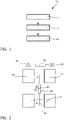
- figure 1 shows a schematic representation of a method 10 according to the invention for displaying the arrangement of components in a vehicle.
- the method 10 comprises the steps of: determining the attachment point 12 of the locked component; determining an adjustment position 14 of the locked component (whereby the determination 12, 14 of the attachment point A, B of the component 38 and the adjustment position of the component 38 is carried out by means of mechanical contact switches connected in series); acoustic and/or visual indication 16 of the attachment point and/or the adjustment position of the component.
- the acoustic and/or visual indication 16 of the fastening point and/or the adjustment position of the component only takes place in the event of an impermissible component arrangement.
- This can be realized by limiting the determination 12, 14 of the point of attachment and the adjustment position of the locked component to impermissible configurations of a component.
- a corresponding evaluation of component arrangements can also first take place electronically in the vehicle.
- FIG 2 shows a representation of an embodiment of a vehicle according to the invention.
- the implementation of a method according to the invention is shown using the example of a removable center console or a center table as the corresponding component 38 .
- These are provided in particular for locking at a fastening point A in the front area of the vehicle between the driver's seat 30 and the passenger seat 32 .
- Additional independent attachment points may be provided elsewhere in the vehicle.
- locking can also take place on the vehicle at a plurality of attachment points A, B along a rail (or a rail system) 36, which also enables the center console to be moved into the area of the rear seating group 34.
- the center console can be equipped with a contact switch (microswitch, reed contact or the like) that detects whether the center console is between the driver's seat 30 and the front passenger's seat 32 .
- a second electronic switch can be used to query whether the console 38 is in a non-permissible driving position (ie, in the lower height setting). The two switches can be connected in series.
- a Electronic unit in the center console ie transmitter or transmitter/receiver unit 40 of component 38 transmits a corresponding signal to a receiver unit integrated in the vehicle (ie transmitter or transmitter/receiver unit 42 of the vehicle), with a means for Determining the attachment point and the adjustment position of the locked component 50 evaluates this signal and thereby determines the attachment point (center console locked on the rail 36 at attachment point A between the driver's seat 30 and the front passenger seat 32) and an adjustment position (lower height setting) of the locked component 38 .
- a corresponding acoustic and/or visual warning message (meaning: center console in impermissible arrangements) can be generated and signaled to the driver, for example, via a corresponding means for acoustic and/or visual display 60 .
- Such a solution has a number of advantages over the aforementioned problems in the prior art.
- This means that the center console can still be moved freely in the rail (or the rail system), even in the first row of seats.
- a mechanical lock that prevents locking of the height adjustment in the first row of seats is not required.
- a center console designed as a center table can also be used in the first row of seats when stationary (ignition off) (e.g. as a work table on one side when the front passenger seat is not occupied).
- This solution can be implemented cost-effectively using a possibly already existing transmitter/receiver unit of the seat occupancy detection.
Landscapes
- Engineering & Computer Science (AREA)
- Mechanical Engineering (AREA)
- Computer Networks & Wireless Communication (AREA)
- Signal Processing (AREA)
- Physics & Mathematics (AREA)
- General Physics & Mathematics (AREA)
- Fittings On The Vehicle Exterior For Carrying Loads, And Devices For Holding Or Mounting Articles (AREA)
Description
- Die Erfindung betrifft ein Verfahren zur Anzeige der Anordnung von Komponenten in einem Fahrzeug. Weiterhin betrifft die Erfindung ein Fahrzeug, bei dem ein erfindungsgemäßes Verfahren zur Anzeige der Anordnung von Komponenten eingesetzt wird.
- Heutige Fahrzeuge verfügen bereits über eine Vielzahl von Assistenzsystemen, die den Fahrer in einer Vielzahl von Fahrsituationen computerbasiert unterstützen. Solche Assistenzsysteme können auf Sensoren zum Erfassen einer Vielzahl von Messdaten zurückgreifen, welche die Sinnesfähigkeiten des Menschen bei weitem übersteigen. Zudem übertrifft die Geschwindigkeit dieser Assistenzsysteme die menschliche Reaktionszeit signifikant. Bekannte Fahrerassistenzsysteme sind beispielsweise Spurhalteassistenten, Bremsassistenten bei Fußgängererkennung und Abstandsregeltempomaten, insbesondere für Stausituationen.
- Zur Erhöhung der Sicherheit der Insassen eines Fahrzeugs werden u.a. auch Sicherheitsassistenzsysteme in die Fahrzeuge integriert. Beispielsweise kann eine drahtlose Sitzbelegungserkennung realisiert werden, die bei entnehmbaren Sitzen im Fahrgastraum überträgt, ob der jeweilige Sitz besetzt ist und ob der zugehörige Sicherheitsgurt ordnungsgemäß angelegt wurde. Eine solche Sitzbelegungserkennung kann kostengünstig über eine Funktechnologie realisiert werden. Vorzugsweise werden hierfür besonders energieeffiziente Nahbereichsverfahren, wie beispielsweise Bluetooth Low Energy (BLE), NFC, WLAN-p oder andere Übertragungstechniken wie induktive Verfahren usw., verwendet. Dazu befindet sich in jedem Sitz eine Sende-Empfangseinheit, die den Zustand des Gurts und einer im Sitz integrierten Sitzbelegungserkennungsmatte auswertet und an das Fahrzeug überträgt. Diese Informationen werden an eine Überwachungseinheit übermittelt, welche zur Bestimmung der Sitzkonfiguration und -belegung die im Fahrzeug vorhanden Sitze regelmäßig abfragt und das Ergebnis an das Fahrzeugsystem weiterleitet. Somit können diese Informationen als Warnungen im Fahrzeug ausgegeben werden.
- Neben entnehmbaren Sitzen sind in Fahrzeugen oftmals auch Komponenten verbaut, die entnehmbar sind und/oder an mehreren Stellen im Fahrzeug arretiert werden können.
- Beispielsweise kann ein Kindersitz oder ein Klapptisch im Fahrzeug vorgesehen sein, welche je nach Bedarf bei bestimmten Befestigungspunkten an unterschiedlichen Stellen im Fahrzeug arretiert werden können. Diese Komponenten weisen zudem oft mehrere Einstellpositionen (im Folgenden auch als Positionen, einstellbare Positionen oder Stellungen bezeichnet) auf, mit denen diese Komponenten unterschiedlich konfiguriert werden können. Ein Kindersitz kann beispielsweise neben einer Sitzposition auch eine bequemere Liegeposition aufweisen. Bei einem Klapptisch können neben einer eingeklappten Aufbewahrungsstellung auch eine oder mehrere Benutzungsstellungen (z.B. halbseitiges Aufklappen jeweils nur einer Tischhälfte) vorgesehen sein.
- Aus Sicherheitsgründen kann es Komponenten geben, die bestimmte Positionen während der Fahrt nicht einnehmen dürfen (sog. unzulässige bzw. nicht empfohlene Komponentenanordnungen). Beispielsweise kann es erforderlich sein, dass bestimmte Klapptische während der Fahrt vollständig verstaut sein müssen, um Verletzungen der Insassen zu vermeiden. Auch kann in einigen Fahrzeugen eine Mittelkonsole vorhanden sein, die beispielsweise entnehmbar, in Schienen längs verschiebbar sowie höhenverstellbar ausgeführt ist. Die verschiedenen Einstellmöglichkeiten mittels der Höhenverstellung stellen unterschiedliche Positionen der Mittelkonsole dar, während eine Arretierung der Mittelkonsole am Fahrzeug an mehreren Befestigungspunkten entlang einer Schiene (bzw. eines Schienensystems) oder anderswo im Fahrzeug vorgesehen sein kann. Ein Befestigungspunkt kann mittig zwischen Fahrer- und Beifahrersitz vorgesehen sein. Ein weiterer Befestigungspunkt könnte sich beispielsweise im Bereich der hinteren Sitzgruppe befinden. Bei den genannten Mittelkonsolen kann beispielsweise aus Gründen der Gebrauchssicherheit bei einer Befestigung zwischen Fahrer- und Beifahrersitz ein Hochfahren der Mittelkonsole in eine obere Einstellposition als unzulässig bzw. als nicht empfohlen angesehen werden. Bevorzugt ist eine Lösung, die eine solche Anordnung im Stand ohne eine Warnung ermöglicht, während im Fahrbetrieb der Nutzer durch geeignete optische und/oder akustische Warnmeldungen zum ordnungsgemäßen Verstauen der Konsole auffordert wird.
- Ein auf die verstellbare Komponente aufgebrachter Warnhinweis mit der Beschreibung des ordnungsgemäßen Gebrauchs ist nicht ausreichend, da solche Warnhinweise im Allgemeinen nur wenig Beachtung finden und zudem nicht alle Befestigungspunkte die gleichen Warnhinweise erfordern. Zudem wäre der Warnhinweis in mehreren Sprachen anzubringen, was ein schnelles Erfassen durch den Benutzer weiter erschwert und zudem die optische Gestaltung des Fahrzeuginnenraums stören würde.
- Möglich wäre weiterhin eine mechanische, vom Fahrzustand des Fahrzeugs unabhängige Lösung zur generellen Verhinderung unzulässiger Komponentenanordnungen, beispielsweise des Hochfahrens einer oben beschriebenen Mittelkonsole an einem kritischen Befestigungspunkt. Solche mechanischen Lösungen haben jedoch neben einer erhöhten mechanischen Komplexität und den damit verbundenen Kosten auch noch den weiteren Nachteil, dass selbst im Stand des Fahrzeugs eine Benutzung der Komponente dadurch verhindert wird. Weiterhin hätte eine solche mechanische Lösung den Nachteil, dass möglicherweise nicht alle Bediener intuitiv verstehen würden, warum sich beispielsweise die Mittelkonsole nicht in die erste Sitzreihe schieben lässt (aufgrund der mechanischen Sperre bei einer hochgefahrenen Mittelkonsole). Dadurch können Beschädigungen an den Bauteilen nicht ausgeschlossen werden. Eine alternative elektronisch schaltbare Sperrvorrichtung würde zwar eine vom Fahrzustand abhängige Sperrung bestimmter Positionen ermöglichen, dies würde jedoch umfangreiche zusätzliche Verkabelungen im Fahrzeug erfordern und durch die Zuschaltbarkeit dieser Sperre in Abhängigkeit des Fahrzeugzustands die mechanische Komplexität weiter erhöhen. Zudem könnte durch eine kabelgebundene Lösung auch die Entnehmbarkeit oder die Beweglichkeit der Komponenten eingeschränkt werden.
- Das beschriebene Problem betrifft sämtliche Fahrzeuge, bei denen die Benutzung bestimmter Komponenten während der Fahrt nicht empfohlen werden soll, und bei denen aufgrund der Entnehmbarkeit oder der Beweglichkeit im Fahrzeug eine kabelgebundene Lösung nicht in Betracht gezogen werden kann. Prinzipiell betrifft dies vor allem Fahrzeuge und Fahrzeugtypen mit variablen Innenräumen sowie in Zukunft auch autonom fahrende Land- und Luftfahrzeuge, bei denen das Fahrzeug (auf Grund des nicht mehr vorhandenen Fahrers) eine Überwachung des Fahrzeugs und die Beachtung des Bordbuches selbstständig vornehmen muss.
-
DE 198 03 682 A1 betrifft eine Beifahrerschutzvorrichtung für ein Fahrzeug, bei der, wenn der Zustand eines Beifahrers in einem vorderen Beifahrersitz (umfassend den festgelegten Zustand eines Kindersitzes) detektiert wird, Airbags auf der Basis des Detektionszustandes gesteuert und der Detektionszustand in einem RAM gespeichert werden können. - Der Erfindung liegt nun die Aufgabe zugrunde, die Probleme des Standes der Technik zu überwinden oder zumindest zu verringern und eine Lösung für das Problem der Verhinderung unzulässiger bzw. nicht empfohlener Komponentenanordnungen in einem Fahrzeug zur Verfügung zu stellen. Die erfindungsgemäße Aufgabe wird gemäß den unabhängigen Patentansprüchen gelöst durch ein Verfahren zur Anzeige der Anordnung von Komponenten in einem Fahrzeug sowie ein Fahrzeug bei dem ein erfindungsgemäßes Verfahren eingesetzt wird. Bevorzugte Weiterbildungen sind Gegenstand der jeweils rückbezogenen Unteransprüche.
- Ein erster Aspekt der Erfindung betrifft ein Verfahren zur Anzeige der Anordnung von Komponenten in einem Fahrzeug, wobei es sich bei den Komponenten um fest an einem oder mehreren Befestigungspunkten im Fahrzeug arretierbare Objekte handelt und die Objekte mindestens zwei verschiedene Einstellpositionen aufweisen. Das Verfahren umfasst die folgenden Schritte: Bestimmung des Befestigungspunktes der arretierten Komponente; Bestimmung einer Einstellposition der arretierten Komponente, wobei die Bestimmung des Befestigungspunktes der Komponente und der Einstellposition der Komponente mittels in Reihe geschalteter mechanischer Kontaktschalter erfolgt; akustische und/oder visuelle Anzeige des Befestigungspunktes und/oder der Einstellposition der Komponente.
- Als entsprechende Komponenten des Fahrzeugs werden somit insbesondere einzelne Einrichtungsgegenstände (Objekte) im Innenraum des Fahrzeugs angesehen. Hierbei kann es sich, wie zuvor bereits ausgeführt, beispielsweise um unterschiedlich anordenbare Klapptische, Mittelkonsolen, allgemeine Konsolenelemente, Kindersitze und weitere Elemente handeln. Diese Komponenten sollen zumindest an einer Stelle im Fahrzeug an einem Befestigungspunkt fest arretierbar sein, ansonsten jedoch auch vollständig aus dem Fahrzeug entnehmbar sein. Weiterhin können im Fahrzeug weitere Befestigungspunkte an anderen Stellen vorgesehen sein, so dass die entnommene Komponente an einer anderen Stelle im Fahrzeug arretiert werden kann. Bei einem Befestigungspunkt kann es sich beispielsweise um eine starre Halterung, eine Arretierungsposition entlang einer Schiene oder eine sonstige Vorrichtung zur Befestigung der Komponente handeln. Weiterhin sollen die Komponenten mindestens zwei verschiedene Einstellpositionen (Konfigurationen) aufweisen, zwischen denen gewählt werden kann. Je nach Komponente kann es sich dabei vorzugsweise um unterschiedlich Lagen (z.B. Sitz-/Liegestellung bei einem Kindersitz) oder Zustände (z.B. ein- bzw. ausgeklappt bei einem Klapptisch) handeln.
- Als Anordnung wird die Zuordnung einer bestimmten Komponente zu einem Befestigungspunkt und einer Einstellposition dieser Komponente bezeichnet. Das erfindungsgemäße Verfahren zur Anzeige der Anordnung von Komponenten in einem Fahrzeug bezieht sich daher auf die Bereitstellung von Informationen über das Vorhandensein und die jeweilige Konfiguration einzelner Komponenten. Diese Anordnungsinformationen können sich insbesondere an den Fahrer des Fahrzeugs richten, so dass dieser der Anzeige beispielsweise den aktuellen Konfigurationszustand seines Fahrzeugs hinsichtlich der genannten Komponenten entnehmen kann. Unter dem Begriff "Bestimmung" ist dabei eine elektronische Ermittlung der Komponentenanordnung in Bezug auf eine ebenfalls elektronisch zu bewirkende Anzeigemöglichkeit zu verstehen, d.h., für eine Anzeige muss vorab eine Information über die Anordnung der jeweiligen Komponente ermittelt werden.
- Der Schritt der Bestimmung des Befestigungspunktes der arretierten Komponente dient der Ermittlung, dass eine entsprechende Komponente im Fahrzeug vorhanden ist und an welcher Stelle im Fahrzeug diese arretiert wurde. Diese Ermittlung bezieht sich auf das Erfassen und Verarbeiten einer entsprechenden Anordnungsinformation. Hierfür kann vorzugsweise über eine mechanische (z.B. vom Befestigungspunkt abhängiges Schalten elektrischer Kontakte) oder elektronische (z.B. mittels RFID-Markierung oder einer anderen geeigneten drahtlosen Übertragungstechnik) Kodierung eine Zuordnung einer Komponente zu einem bestimmten Befestigungspunkt im Fahrzeug erfolgen. Wird beispielsweise eine entsprechende Komponente in einem solchen Befestigungspunkt arretiert, so sollte eine Information über die Art der Komponente und den zur Arretierung genutzten Befestigungspunkt vorliegen. Das Ergebnis der Bestimmung des Befestigungspunktes soll in elektronischer Form vorliegen, die Bestimmung an sich kann jedoch auch mechanische Vorgänge, wie etwa die Betätigung eines Kontaktschalters, beinhalten.
- Der Schritt der Bestimmung einer Einstellposition der arretierten Komponente ist analog zu verstehen. Letztlich soll das Ergebnis der Bestimmung, in welcher Einstellposition sich die arretierte Komponente gerade befindet, ebenfalls elektronisch vorliegen. Auch hierbei kann die Bestimmung auch mechanische Vorgänge, wie etwa die Betätigung eines positionsabhängigen Schalters, beinhalten.
- Nach der Bestimmung des Befestigungspunktes und einer Einstellposition der arretierten Komponente liegen diese Informationen in elektronischer Form im Fahrzeug vor. Diese Informationen können dann beispielweise akustisch mittels Lautsprecherausgabe und/oder visuell als Lichtsignal oder in einem Display angezeigt werden oder eine andere Form der Benachrichtigung der Insassen (z.B. Nachrichten auf das Smartphone des Nutzers) beinhalten. Dabei muss die Anzeige jedoch nicht die vollständige Information explizit wiedergeben. Es reicht aus, wenn der Anzeige auch nur indirekt Angaben darüber zu entnehmen sind, dass eine unzulässige Komponentenanordnung im Fahrzeug vorliegt. Insbesondere kann sich die Anzeige auf einen Hinweis auf eine bestimmte unzulässige Einstellposition einer Komponente beschränken. Eine akustische Anzeige der Anordnung kann beispielsweise durch ein bestimmtes Schallsignal wie einen Gong oder ein Klingeln erfolgen, es könnte jedoch auch eine konkrete sprachliche Ansage erfolgen, etwa dass ein Klapptisch im hinteren Bereich des Fahrzeugs gerade eine andere Position eingenommen hat. Unter einer visuellen Anzeige ist insbesondere eine symbolhafte oder sprachliche Darstellung der entsprechenden Informationen in einem Display, beispielsweise einem Head-up-Display (HUD) oder einem Kombiinstrument des Fahrzeugs, zu verstehen. Der Fahrer kann somit eindeutig über eine unzulässige Komponentenanordnung informiert werden. Es ist dabei keine Verwechselung oder Verwirrung des Fahrers zu erwarten.
- Die Idee der Erfindung ist somit, den Insassen des Fahrzeugs Informationen über die Anordnung von entsprechenden Komponenten im Fahrzeug zur Verfügung stellen zu können, ohne dass die Insassen diese im Blick haben oder speziell darauf achten müssten. Insbesondere sollen dadurch unzulässige Komponentenanordnungen in einem Fahrzeug während des Fahrbetriebs verhindert werden. Hierfür sollen die Insassen und insbesondere der Fahrer des Fahrzeugs gesondert auf das Vorliegen einer solchen unzulässigen Komponentenanordnung hingewiesen werden. Der Fahrer bzw. Nutzer einer Fahrzeugs darf eine solche Anordnung somit im Stand ohne eine Warnung verwenden, während er im Fahrbetrieb durch geeignete optische und/oder akustische Warnmeldungen über die Unzulässigkeit dieser Anordnung informiert werden kann. Auf eine mehrsprachige Instruktion, z.B. über ein auf die jeweilige Komponente aufgebrachtes Hinweisschild, kann verzichtet werden, da zusätzlich zu einem ausgegebenen Hinweis auch klare Handlungsempfehlungen an die Benutzer des Fahrzeugs übermittelt werden können.
- In bevorzugter Ausgestaltung der Erfindung ist vorgesehen, dass zur Bestimmung des Befestigungspunktes der Komponente und einer Einstellposition der Komponente Anordnungsinformationen zwischen der Komponente und dem Fahrzeug kabellos über eine Funkverbindung übertragen werden. Dies hat den Vorteil, dass keine Kabelverbindung zum jeweiligen Befestigungspunkt geführt werden muss. Insbesondere können die Befestigungspunkte als passive Komponenten ausgeführt sein, die lediglich eine mechanische Arretierung der Komponente ermöglichen. Vorzugsweise ist der Befestigungspunkt bei einer Arretierung jedoch durch die Komponente individualisiert über eine Kodierung erkennbar. Diese Kodierung kann insbesondere mechanisch (z.B. mittels einer individueller Formung des Befestigungspunktes), optisch (z.B. durch einen aufgebrachten Barcode) oder elektronisch (z.B. mittels RFID-Markierung oder einer anderen geeigneten drahtlosen Übertragungstechnik) erfolgen. Die Funkverbindung wird vorzugsweise zwischen der Komponente und dem Fahrzeug aufgebaut. Alternativ kann eine entsprechende Sendeeinrichtung jedoch auch am Befestigungspunkt vorgesehen sein.
- Bevorzugt wird die Funkverbindung zwischen einem Sendemodul der Komponente und einem Empfangsmodul des Fahrzeugs aufgebaut, wobei das fahrzeugseitige Empfangsmodul zur Verwendung mit einer Vielzahl von Komponenten eingerichtet ist. Dies hat den Vorteil, dass das fahrzeugseitige Empfangsmodul als zentrale Gegenstelle für mehrere Komponenten genutzt werden kann und nur einmalig im Fahrzeug vorhanden sein muss. Insbesondere kann es sich hierbei auch um ein bereits im Fahrzeug für andere Informationsübertragungsfunktionen eingerichtetes Empfangsmodul, beispielsweise ein auch für die drahtlose Sitzbelegungserkennung genutztes Sende-/Empfangsmodul, handeln. Bei einem in der Komponente angeordneten Sendemodul kann es ich insbesondere um einen energiesparenden batteriebetriebenen Sender handeln. Eine solche Komponente benötigt keine zusätzliche Energieversorgung am Befestigungspunkt und kann daher auf elektronische Kontakte und eine externe Verkabelung verzichten. Vorzugsweise wird die Funkverbindung mittels Bluetooth Low Energy (BLE) oder 5G aufbaut, welche die momentan energiesparendsten Übertragungsplattformen darstellen. Ebenfalls bevorzugt sind Funkverbindungen mittels NFC, WLAN-p oder über andere Übertragungstechniken wie induktive Verfahren. Dadurch wird eine wartungsfreie Funktion der Komponenten über einen langen Zeitraum gewährleistet und eine Energieversorgung kann über mehrere Jahre sichergestellt werden.
- In einer alternativen Ausführungsform kann die Komponente auch ein Empfangsmodul bzw. ein kombiniertes Sende-/Empfangsmodul umfassen. Dadurch können weitere Funktionen wie eine aktive Abfrage der Komponente, beispielsweise zu deren Anordnung oder zum Zustand einer in der Komponente integrierten Batterie erfolgen. Im Fahrzeug muss dann ein entsprechendes Empfangsmodul bzw. ein kombiniertes Sende-/Empfangsmodul vorhanden sein. Ein nur passives Senden der Komponenten hat den Nachteil, dass dieses Senden unabhängig vom Nutzungszustand des Fahrzeugs erfolgt.
- Eine weitere Möglichkeit zur Energieeinsparung besteht darin, dass die arretierte Komponente regelmäßig (d.h. nicht kontinuierlich) Informationen zum Befestigungspunkt und/oder zu einer Einstellposition der Komponente an das Fahrzeug übermittelt. Eine Übermittlung könnte beispielsweise in zeitlichem Abstand von einigen Sekunden erfolgen.
- In bevorzugter Ausgestaltung der Erfindung ist vorgesehen, dass die akustische und/oder visuelle Anzeige des Befestigungspunktes und/oder der Einstellposition der Komponente nur bei einer unzulässigen Anordnung der Komponente erfolgt. Eine solche Anzeige wird dann vorzugsweise als Warnmeldung besonders hervorgehoben ausgegeben.
- Eine Einschränkung der Anzeige auf unzulässige Komponentenanordnungen kann zum einen dadurch geschehen, dass schon die Bestimmung des Befestigungspunktes und der Einstellposition der arretierten Komponente auf unzulässige Anordnungen der Komponente beschränkt sind. Da somit nur unzulässige Komponentenanordnungen bestimmt werden, ist eine Anzeige auf solche unzulässigen Anordnungen der Komponenten beschränkt.
- Alternativ kann eine entsprechende Auswertung von Komponentenanordnungen auch erst elektronisch im Fahrzeug erfolgen. Dies bedeutet, dass im Fahrzeug Informationen über unzulässige oder alle zulässigen Komponentenanordnungen in elektronsicher Form hinterlegt sind und diese bei der Anzeige mit berücksichtigt werden. Ein entsprechendes Mittel zur Auswertung vergleicht dann diese hinterlegten Informationen mit den sich aus den einzelnen verfahrensgemäßen Bestimmungen ergebenden Informationen und wertet diese aus. Ergibt die Prüfung, dass eine unzulässige Anordnung einer Komponente vorliegt, erfolgt eine entsprechende Anzeige im Fahrzeug.
- Die Bestimmung des Befestigungspunktes der Komponente und einer Einstellposition der Komponente erfolgt mittels in Reihe geschalteter mechanischer Kontaktschalter. Hierbei kann es sich beispielsweise um Mikroschalter, Reed-Kontakte oder ähnliches handeln. Beispielsweise kann der erste Kontaktschalter durch Arretierung an einem bestimmten Befestigungspunkt geschaltet werden. Der zweite elektronische Schalter kann bei einer bestimmten Einstellposition geschaltet werden. Insbesondere können dann bei einer unzulässigen Komponentenanordnung, d.h. bei einer bestimmten nicht gewünschten Kombination aus Befestigungspunkt und Einstellposition, beide Kontaktschalter geschlossen werden und dadurch eine entsprechende Bestimmung der Anordnung ermöglichen. Beispielsweise kann durch die in Reihe geschalteten mechanischer Kontaktschalter eine in der Komponente vorhanden Sendeeinheit zum Aufbau einer Funkverbindung aktiviert werden.
- Ein weiter Aspekt der vorliegenden Erfindung betrifft ein Fahrzeug umfassend eine Komponente, wobei es sich bei der Komponente um ein fest an einem oder mehreren Befestigungspunkten im Fahrzeug arretierbares Objekt handelt, das Objekt mindestens zwei verschiedene Einstellpositionen aufweist und das Fahrzeug und die Komponente zur Durchführung eines Verfahrens nach einem der vorhergehenden Ansprüche eingerichtet sind.
- Hierzu kann das Fahrzeug ein Mittel zur Ermittlung des Befestigungspunktes und der Einstellposition der Komponente sowie ein Mittel zur akustischen und/oder visuellen Anzeige des Befestigungspunktes und/oder der Einstellposition der Komponente aufweisen. Bei dem Mittel zur Ermittlung des Befestigungspunktes und der Einstellposition der Komponente kann es sich insbesondere um eine elektronische Schaltung handeln, welche die elektronischen Informationen für das Mittel zur Anzeige bereitstellt. Dem Mittel zur Ermittlung des Befestigungspunktes und der Einstellposition der Komponente können weitere Bauelemente zur Bestimmung des Befestigungspunktes der Komponente und einer Einstellposition der Komponente vor- und nachgeschaltet sein. Hierbei kann es sich beispielweise um Kontaktschalter, Funkeinrichtungen und ein eventuell vorhandenes Mittel zur Auswertung der von der Komponente übertragenen Informationen gezählt.
- Vorzugsweise weist das Fahrzeug ein Empfangsmodul und die Komponente ein Sendemodul auf, welche dazu eingerichtet sind, Anordnungsinformationen zwischen der Komponente und dem Fahrzeug kabellos über eine Funkverbindung zu übertragen. Weiterhin kann das Fahrzeug auch ein entsprechendes Sendemodul (oder ein kombiniertes Sende-/Empfangsmodul) und die Komponente ein Empfangsmodul (oder ein kombiniertes Sende-/Empfangsmodul) aufweisen. Dadurch können auch bidirektionale Funkverbindungen zwischen dem Fahrzeug und den einzelnen Komponenten aufgebaut werden. Dies ermöglicht ein gezieltes Abfragen einzelner Komponenten, beispielsweise hinsichtlich ihrer Anordnung oder ihres Batteriezustandes.
- Weitere bevorzugte Ausgestaltungen der Erfindung ergeben sich aus den übrigen, in den Unteransprüchen genannten Merkmalen.
- Die verschiedenen in dieser Anmeldung genannten Ausführungsformen der Erfindung sind, sofern im Einzelfall nicht anders ausgeführt, mit Vorteil miteinander kombinierbar.
- Die Erfindung wird nachfolgend in Ausführungsbeispielen anhand der zugehörigen Zeichnungen erläutert. Es zeigen:
- Figur 1
- eine schematische Darstellung eines erfindungsgemäßen Verfahrens zur Anzeige der Anordnung von Komponenten in einem Fahrzeug, und
- Figur 2
- eine Darstellung einer Ausführungsform eines erfindungsgemäßen Fahrzeugs.
-
Figur 1 zeigt eine schematische Darstellung eines erfindungsgemäßen Verfahrens 10 zur Anzeige der Anordnung von Komponenten in einem Fahrzeug. Für Fahrzeuge, welche entnehmbare und fest an einem oder mehreren Befestigungspunkten im Fahrzeug arretierbare Komponenten mit mindestens zwei verschiedenen Einstellpositionen aufweisen, umfasst das Verfahren 10 die Schritte: Bestimmung des Befestigungspunktes 12 der arretierten Komponente; Bestimmung einer Einstellposition 14 der arretierten Komponente (wobei die Bestimmung 12, 14 des Befestigungspunktes A, B der Komponente 38 und der Einstellposition der Komponente 38 mittels in Reihe geschalteter mechanischer Kontaktschalter erfolgt); akustische und/oder visuelle Anzeige 16 des Befestigungspunktes und/oder der Einstellposition der Komponente. Vorzugsweise erfolgt die akustische und/oder visuelle Anzeige 16 des Befestigungspunktes und/oder der Einstellposition der Komponente nur bei einer unzulässigen Komponentenanordnung. Dies kann dadurch realisiert werden, dass die Bestimmung 12, 14 des Befestigungspunktes und der Einstellposition der arretierten Komponente auf unzulässige Anordnungen einer Komponente beschränkt wird. Alternativ kann eine entsprechende Auswertung von Komponentenanordnungen auch erst elektronisch im Fahrzeug erfolgen. -
Figur 2 zeigt eine Darstellung einer Ausführungsform eines erfindungsgemäßen Fahrzeugs. Es wird die Umsetzung eines erfindungsgemäßen Verfahrens am Beispiel einer entnehmbaren Mittelkonsole bzw. eines Mitteltisches als entsprechende Komponente 38 gezeigt. Diese sind insbesondere zur Arretierung an einem Befestigungspunkt A im vorderen Fahrzeugbereich zwischen Fahrersitz 30 und Beifahrersitz 32 vorgesehen. Weitere unabhängige Befestigungspunkte können anderswo im Fahrzeug vorgesehen sein. Eine Arretierung kann am Fahrzeug wie dargestellt auch an mehreren Befestigungspunkten A, B entlang einer Schiene (bzw. eines Schienensystems) 36 erfolgen, wodurch eine Verschiebung der Mittelkonsole auch in den Bereich der hinteren Sitzgruppe 34 ermöglicht wird. Hinsichtlich der möglichen Einstellpositionen der Mittelkonsole wird vereinfacht angenommen, dass diese im Wesentlichen zwei unterschiedliche Höheneinstellungen, d.h. eine untere und eine obere Höhenposition, erlaubt. Als eine unzulässige Komponentenanordnung wird aus Gründen der Gebrauchssicherheit eine Arretierung am vorderen Befestigungspunkt A bei einer oberen Höheneinstellung angesehen. Durch die Erfindung sollen solche unzulässigen Komponentenanordnungen in einem Fahrzeug effektiv verhindert werden. - Dazu kann die Mittelkonsole mit einem Kontaktschalter (Mikroschalter, Reed-Kontakt oder ähnliches) ausgestattet werden, der erkennt, ob sich die Mittelkonsole zwischen dem Fahrersitz 30 und dem Beifahrersitz 32 befindet. Ein zweiter elektronischer Schalter kann zur Abfrage genutzt werden, ob sich die Konsole 38 in einer anderen als der zulässigen Fahrposition (d.h. in der unteren Höheneinstellung) befindet. Die beiden Schalter können in Reihe geschaltet sein. Wenn nun die Mittelkonsole auf der Schiene 36 zwischen dem Fahrersitz 30 und dem Beifahrersitz 32 arretiert ist und sich nicht in der unteren Höheneinstellung befindet, dann kann über eine elektronische Einheit in der Mittelkonsole (d.h. Sende- bzw. Sende-/Empfangseinheit 40 der Komponente 38) ein entsprechendes Signal an eine im Fahrzeug integrierte Empfangseinheit (d.h. Sende- bzw. Sende-/Empfangseinheit 42 des Fahrzeugs) übermittelt werden, wobei ein Mittel zur Ermittlung des Befestigungspunktes und der Einstellposition der arretierten Komponente 50 dieses Signal auswertet und dadurch eine Bestimmung des Befestigungspunktes (Mittelkonsole auf der Schiene 36 am Befestigungspunkt A zwischen dem Fahrersitz 30 und dem Beifahrersitz 32 arretiert) und einer Einstellposition (untere Höheneinstellung) der arretierten Komponente 38 vornimmt. Daraus kann eine entsprechende akustische und/oder visuelle Warnmeldung (sinngemäß: Mittelkonsole in unzulässiger Anordnungen) erzeugt und über ein entsprechendes Mittel zur akustischen und/oder visuellen Anzeige 60 beispielsweise dem Fahrer signalisiert werden.
- Eine solche Lösung weist eine Vielzahl von Vorteilen gegenüber den zuvor genannten Problemen im Stand der Technik auf. Die Mittelkonsole kann dadurch weiterhin frei in der Schiene (bzw. dem Schienensystem) bewegt werden, auch in die erste Sitzreihe. Eine mechanische Sperre, die das Verriegeln der Höhenverstellung in der ersten Sitzreihe verhindert, ist dabei nicht erforderlich. Eine als Mitteltisch ausgebildet Mittelkonsole kann im Stand (Zündung aus) ebenfalls in der ersten Sitzreihe verwendet werden (beispielsweise als halbseitiger Arbeitstisch bei nicht besetztem Beifahrersitz). Durch eine eventuell schon vorhandene Sende-Empfangseinheit der Sitzbelegungserkennung ist diese Lösung kostengünstig realisierbar.
-
- 10
- Verfahren zur Anzeige der Anordnung von Komponenten
- 12
- Bestimmung des Befestigungspunktes einer arretierten Komponente
- 14
- Bestimmung einer Einstellposition einer arretierten Komponente
- 16
- akustische und/oder visuelle Anzeige
- 30
- Fahrersitz
- 32
- Beifahrersitz
- 34
- hintere Sitzgruppe
- 36
- Schiene (bzw. Schienensystem) mit unterschiedlichen Befestigungspunkten
- 38
- Komponente (Mittelkonsole/Mitteltisch mit unterschiedlichen Höhenpositionen)
- 40
- Sende- bzw. Sende-/Empfangseinheit der Komponente
- 42
- Sende- bzw. Sende-/Empfangseinheit des Fahrzeugs
- 50
- Mittel zur Ermittlung des Befestigungspunktes und einer Einstellposition einer arretierten Komponente
- 60
- Mittel zur akustischen und/oder visuelle Anzeige
- A, B
- Befestigungspunkte
Claims (10)
- Verfahren (10) zur Anzeige der Anordnung von Komponenten (38) in einem Fahrzeug, wobei es sich bei den Komponenten (38) um fest an einem oder mehreren Befestigungspunkten (A, B) im Fahrzeug arretierbare Objekte handelt und die Objekte mindestens zwei verschiedene Einstellpositionen aufweisen, folgende Schritte umfassend:- Bestimmung (12) des Befestigungspunktes (A, B) der arretierten Komponente (38);- Bestimmung (14) einer Einstellposition der arretierten Komponente (38), wobei die Bestimmung (12, 14) des Befestigungspunktes (A, B) der Komponente (38) und der Einstellposition der Komponente (38) mittels in Reihe geschalteter mechanischer Kontaktschalter erfolgt;- akustische und/oder visuelle Anzeige (16) des Befestigungspunktes (A, B) und/oder der Einstellposition der Komponente (38).
- Verfahren nach Anspruch 1, wobei zur Bestimmung (12, 14) des Befestigungspunktes (A, B) der Komponente (38) und einer Einstellposition der Komponente (38) Anordnungsinformationen zwischen der Komponente (38) und dem Fahrzeug kabellos über eine Funkverbindung übertragen werden.
- Verfahren nach Anspruch 2, wobei die Funkverbindung zwischen einem Sendemodul (40) der Komponente (38) und einem Empfangsmodul (42) des Fahrzeugs aufgebaut wird, wobei das fahrzeugseitige Empfangsmodul (42) zur Verwendung mit einer Vielzahl von Komponenten (38) eingerichtet ist.
- Verfahren nach Anspruch 2 oder 3, wobei die Funkverbindung mittels Bluetooth Low Energy, 5G, NFC, oder WLAN-p aufgebaut wird.
- Verfahren nach einem der vorhergehenden Ansprüche, wobei die arretierte Komponente (38) regelmäßig Informationen zum Befestigungspunkt (A, B) der Komponente (38) und/oder zu seiner Einstellposition an das Fahrzeug übermittelt.
- Verfahren nach einem der vorhergehenden Ansprüche, wobei die akustische und/oder visuelle Anzeige (16) des Befestigungspunktes (A, B) und/oder der Einstellposition der Komponente (38) nur bei einer unzulässigen Anordnung der Komponente (38) erfolgt.
- Verfahren nach einem der vorhergehenden Ansprüche, wobei eine aktive Abfrage der Komponente (38) mittels eines von der Komponente (38) umfassten Empfangsmoduls oder eines kombinierten Sende-/Empfangsmoduls erfolgt.
- Fahrzeug umfassend eine Komponente (38), wobei es sich bei der Komponente um ein fest an einem oder mehreren Befestigungspunkten (A, B) im Fahrzeug arretierbares Objekt handelt, das Objekt mindestens zwei verschiedene Einstellpositionen aufweist und das Fahrzeug und die Komponente (38) zur Durchführung eines Verfahrens (10) nach einem der vorhergehenden Ansprüche eingerichtet sind.
- Fahrzeug nach Anspruch 8, wobei das Fahrzeug ein Mittel zur Ermittlung des Befestigungspunktes und der Einstellposition (50) der Komponente (38) sowie ein Mittel zur akustischen und/oder visuellen Anzeige (60) des Befestigungspunktes (A, B) und/oder der Einstellposition der Komponente (38) aufweist.
- Fahrzeug nach Anspruch 8 oder 9, wobei das Fahrzeug ein Empfangsmodul (42) und die Komponente (38) ein Sendemodul (40) aufweisen, dazu eingerichtet, Anordnungsinformationen zwischen der Komponente (38) und dem Fahrzeug kabellos über eine Funkverbindung zu übertragen.
Applications Claiming Priority (1)
| Application Number | Priority Date | Filing Date | Title |
|---|---|---|---|
| DE102019208932.1A DE102019208932A1 (de) | 2019-06-19 | 2019-06-19 | Verfahren zur Anzeige der Anordnung von Komponenten in einem Fahrzeug |
Publications (2)
| Publication Number | Publication Date |
|---|---|
| EP3753791A1 EP3753791A1 (de) | 2020-12-23 |
| EP3753791B1 true EP3753791B1 (de) | 2022-09-14 |
Family
ID=71409085
Family Applications (1)
| Application Number | Title | Priority Date | Filing Date |
|---|---|---|---|
| EP20180355.8A Active EP3753791B1 (de) | 2019-06-19 | 2020-06-16 | Verfahren zur anzeige der anordnung von komponenten in einem fahrzeug |
Country Status (4)
| Country | Link |
|---|---|
| US (1) | US11120649B2 (de) |
| EP (1) | EP3753791B1 (de) |
| CN (1) | CN112109640B (de) |
| DE (1) | DE102019208932A1 (de) |
Families Citing this family (3)
| Publication number | Priority date | Publication date | Assignee | Title |
|---|---|---|---|---|
| DE102021109828A1 (de) | 2021-04-19 | 2022-10-20 | Brose Fahrzeugteile Se & Co. Kommanditgesellschaft, Bamberg | Verstellsystem für den Fahrzeuginnenraum mit Möglichkeit zur Erzeugung eines visuellen Hinweises auf ein potentielles Hindernis |
| CN117048444A (zh) * | 2022-06-08 | 2023-11-14 | 北京罗克维尔斯科技有限公司 | 车辆座椅的调整方法及装置、车辆、电子设备和存储介质 |
| JP2024140746A (ja) * | 2023-03-28 | 2024-10-10 | 本田技研工業株式会社 | 通話サポートシステム、通話サポート方法、及びプログラム |
Family Cites Families (14)
| Publication number | Priority date | Publication date | Assignee | Title |
|---|---|---|---|---|
| JP3007775B2 (ja) * | 1993-10-19 | 2000-02-07 | 自動車電機工業株式会社 | 電動シート装置 |
| JP3834803B2 (ja) | 1997-01-30 | 2006-10-18 | マツダ株式会社 | 車両用エアバックシステム及び車両用乗員拘束システム |
| JP3374739B2 (ja) * | 1998-01-09 | 2003-02-10 | トヨタ自動車株式会社 | 車両用チャイルドシート検知システム |
| JP2002019530A (ja) * | 2000-07-04 | 2002-01-23 | Kasai Kogyo Co Ltd | 車両用コンソールボックス |
| US20050189805A1 (en) * | 2004-03-01 | 2005-09-01 | Edward Burley | Lower anchor and tethers for children (latch) detection and measurement device |
| US8840184B2 (en) * | 2011-10-06 | 2014-09-23 | Thorley Industries Llc | Child restraint system with automated installation |
| AU2012323288A1 (en) * | 2011-10-10 | 2014-05-29 | Cars-N-Kids Llc | Systems and methods for monitoring the orientation, tensioning, and installation of a child safety restraint |
| DE102012208644B4 (de) * | 2011-11-23 | 2014-02-27 | Johnson Controls Gmbh | Vorrichtung und Verfahren zur Anpassung einer Sitzposition |
| US10328841B2 (en) | 2015-07-31 | 2019-06-25 | GM Global Technology Operations LLC | Automated wireless securement-monitoring and feedback system |
| US9663032B1 (en) * | 2015-11-09 | 2017-05-30 | Ford Global Technologies, Llc | Child seat monitoring system and method |
| JP6298091B2 (ja) * | 2016-03-18 | 2018-03-20 | 株式会社Subaru | 車両用シート装置 |
| US11148555B2 (en) * | 2017-04-03 | 2021-10-19 | Firasat Ali | System and method for securing and monitoring a child placed in a car seat of a vehicle |
| US10252640B2 (en) * | 2017-08-21 | 2019-04-09 | Joyson Safety Systems Acquisition Llc | Seatbelt and child seat anchor based occupancy detection system |
| CN109835215B (zh) * | 2019-01-31 | 2020-06-16 | 宁波环球娃娃婴童用品股份有限公司 | 一种儿童安全座椅的椅背正反向安装检测系统及检测方法 |
-
2019
- 2019-06-19 DE DE102019208932.1A patent/DE102019208932A1/de not_active Withdrawn
-
2020
- 2020-06-16 EP EP20180355.8A patent/EP3753791B1/de active Active
- 2020-06-18 US US16/904,771 patent/US11120649B2/en active Active
- 2020-06-19 CN CN202010564782.7A patent/CN112109640B/zh active Active
Also Published As
| Publication number | Publication date |
|---|---|
| US20200402329A1 (en) | 2020-12-24 |
| US11120649B2 (en) | 2021-09-14 |
| DE102019208932A1 (de) | 2020-12-24 |
| CN112109640B (zh) | 2024-10-29 |
| EP3753791A1 (de) | 2020-12-23 |
| CN112109640A (zh) | 2020-12-22 |
Similar Documents
| Publication | Publication Date | Title |
|---|---|---|
| DE10203139B4 (de) | Verfahren und Vorrichtung zur Überwachung des Gebrauchs des Rücksitzgurts | |
| EP3753791B1 (de) | Verfahren zur anzeige der anordnung von komponenten in einem fahrzeug | |
| EP2752036B1 (de) | Kraftfahrzeug | |
| DE102007055088B4 (de) | Sitz mit einem Sitzelement, Sitzanordnung und Verfahren zur Überwachung eines Sitzes | |
| DE102013210785B4 (de) | Warnsysteme und -verfahren für ein fahrzeug | |
| EP3494044B1 (de) | Überwachungsmodul für einen sitzplatz eines passagierflugzeuges, überwachungseinrichtung und passagierflugzeug | |
| DE102013211029B4 (de) | Fahrzeugsitzanordnung und Fahrerwarnanordnung | |
| DE102013211158A1 (de) | Warnsysteme und -verfahren für ein fahrzeug mit verbesserter aktuator-platzierung | |
| DE60207304T2 (de) | Elektrostimulationsvorrichtung für benutzer von transportmitteln | |
| DE102012001939B4 (de) | Verfahren und Vorrichtung zur Erfassung eines im Fahrzeug zurückgelassenen Mobilgeräts und Fahrzeug | |
| DE102020105627A1 (de) | Verfahren zum Steuern eines Kraftfahrzeugs mittels eines fahrzeugexternen mobilen Endgeräts sowie System mit einem Kraftfahrzeug und einem mobilen Endgerät, sowie ein Kraftfahrzeug und ein mobiles Endgerät | |
| DE102012207579A1 (de) | System und Verfahren zum automatischen Freigeben eines Automodus in einer persönlichen Kommunikationseinrichtung | |
| DE102021200898A1 (de) | Schätzung eines Fahrer-Ablenkungsgrades | |
| DE102013005073A1 (de) | Verfahren und Warnvorrichtung zur Absicherung einer Gefahrenstelle, insbesondere im Straßenverkehr | |
| DE102009038580A1 (de) | Verfahren und Vorrichtung zur Erfassung eines im Fahrzeug zurückgelassenen Mobilgeräts | |
| DE10116190C1 (de) | Vorrichtung zur Insassenwarnung in einem Fahrzeug | |
| DE102013214906A1 (de) | Vorrichtung und Verfahren zum Senden von statischen und dynamischen Informationen an ein persönliches Kommunikationsgerät in einem Fahrzeug | |
| DE102021133980A1 (de) | Automatische externe Informationsanzeige eines Fahrzeugs | |
| DE102007056804B4 (de) | Fernbedienungssystem | |
| DE102013016879A1 (de) | Verfahren zum Bedienen von Fahrzeugfunktionen | |
| DE102012214673A1 (de) | Verfahren und System zum Informationsvorhalten bei einer Bergung eines verunfallten Kraftfahrzeugs, kabellos kommunizierender Informationsgeber sowie Verwendungen des Informationsgebers | |
| EP1008496B1 (de) | Vorrichtung zur Überwachung der Sitzposition eines Fahrzeuginsassen | |
| DE102012006863A1 (de) | Erkennungs- und Überwachungseinrichtung und -verfahren für einen Schalt- und/oder Schließzustand eines Schlosses | |
| DE102021106460A1 (de) | Detektionseinrichtung, Kraftfahrzeug und Verfahren zur Detektion eines Lebewesens in einem Kraftfahrzeug | |
| DE102004007788A1 (de) | Kinderkomfortsystem für ein Kraftfahrzeug |
Legal Events
| Date | Code | Title | Description |
|---|---|---|---|
| PUAI | Public reference made under article 153(3) epc to a published international application that has entered the european phase |
Free format text: ORIGINAL CODE: 0009012 |
|
| STAA | Information on the status of an ep patent application or granted ep patent |
Free format text: STATUS: THE APPLICATION HAS BEEN PUBLISHED |
|
| AK | Designated contracting states |
Kind code of ref document: A1 Designated state(s): AL AT BE BG CH CY CZ DE DK EE ES FI FR GB GR HR HU IE IS IT LI LT LU LV MC MK MT NL NO PL PT RO RS SE SI SK SM TR |
|
| AX | Request for extension of the european patent |
Extension state: BA ME |
|
| STAA | Information on the status of an ep patent application or granted ep patent |
Free format text: STATUS: REQUEST FOR EXAMINATION WAS MADE |
|
| 17P | Request for examination filed |
Effective date: 20210623 |
|
| RBV | Designated contracting states (corrected) |
Designated state(s): AL AT BE BG CH CY CZ DE DK EE ES FI FR GB GR HR HU IE IS IT LI LT LU LV MC MK MT NL NO PL PT RO RS SE SI SK SM TR |
|
| GRAP | Despatch of communication of intention to grant a patent |
Free format text: ORIGINAL CODE: EPIDOSNIGR1 |
|
| STAA | Information on the status of an ep patent application or granted ep patent |
Free format text: STATUS: GRANT OF PATENT IS INTENDED |
|
| RIC1 | Information provided on ipc code assigned before grant |
Ipc: B60R 21/015 20060101ALI20220211BHEP Ipc: B60R 16/037 20060101ALI20220211BHEP Ipc: B60R 16/023 20060101AFI20220211BHEP |
|
| INTG | Intention to grant announced |
Effective date: 20220228 |
|
| GRAS | Grant fee paid |
Free format text: ORIGINAL CODE: EPIDOSNIGR3 |
|
| GRAA | (expected) grant |
Free format text: ORIGINAL CODE: 0009210 |
|
| STAA | Information on the status of an ep patent application or granted ep patent |
Free format text: STATUS: THE PATENT HAS BEEN GRANTED |
|
| AK | Designated contracting states |
Kind code of ref document: B1 Designated state(s): AL AT BE BG CH CY CZ DE DK EE ES FI FR GB GR HR HU IE IS IT LI LT LU LV MC MK MT NL NO PL PT RO RS SE SI SK SM TR |
|
| REG | Reference to a national code |
Ref country code: GB Ref legal event code: FG4D Free format text: NOT ENGLISH |
|
| REG | Reference to a national code |
Ref country code: CH Ref legal event code: EP |
|
| REG | Reference to a national code |
Ref country code: DE Ref legal event code: R096 Ref document number: 502020001691 Country of ref document: DE |
|
| REG | Reference to a national code |
Ref country code: IE Ref legal event code: FG4D Free format text: LANGUAGE OF EP DOCUMENT: GERMAN |
|
| REG | Reference to a national code |
Ref country code: AT Ref legal event code: REF Ref document number: 1518514 Country of ref document: AT Kind code of ref document: T Effective date: 20221015 |
|
| REG | Reference to a national code |
Ref country code: LT Ref legal event code: MG9D |
|
| REG | Reference to a national code |
Ref country code: NL Ref legal event code: MP Effective date: 20220914 |
|
| PG25 | Lapsed in a contracting state [announced via postgrant information from national office to epo] |
Ref country code: SE Free format text: LAPSE BECAUSE OF FAILURE TO SUBMIT A TRANSLATION OF THE DESCRIPTION OR TO PAY THE FEE WITHIN THE PRESCRIBED TIME-LIMIT Effective date: 20220914 Ref country code: RS Free format text: LAPSE BECAUSE OF FAILURE TO SUBMIT A TRANSLATION OF THE DESCRIPTION OR TO PAY THE FEE WITHIN THE PRESCRIBED TIME-LIMIT Effective date: 20220914 Ref country code: NO Free format text: LAPSE BECAUSE OF FAILURE TO SUBMIT A TRANSLATION OF THE DESCRIPTION OR TO PAY THE FEE WITHIN THE PRESCRIBED TIME-LIMIT Effective date: 20221214 Ref country code: LV Free format text: LAPSE BECAUSE OF FAILURE TO SUBMIT A TRANSLATION OF THE DESCRIPTION OR TO PAY THE FEE WITHIN THE PRESCRIBED TIME-LIMIT Effective date: 20220914 Ref country code: LT Free format text: LAPSE BECAUSE OF FAILURE TO SUBMIT A TRANSLATION OF THE DESCRIPTION OR TO PAY THE FEE WITHIN THE PRESCRIBED TIME-LIMIT Effective date: 20220914 Ref country code: FI Free format text: LAPSE BECAUSE OF FAILURE TO SUBMIT A TRANSLATION OF THE DESCRIPTION OR TO PAY THE FEE WITHIN THE PRESCRIBED TIME-LIMIT Effective date: 20220914 |
|
| PG25 | Lapsed in a contracting state [announced via postgrant information from national office to epo] |
Ref country code: HR Free format text: LAPSE BECAUSE OF FAILURE TO SUBMIT A TRANSLATION OF THE DESCRIPTION OR TO PAY THE FEE WITHIN THE PRESCRIBED TIME-LIMIT Effective date: 20220914 Ref country code: GR Free format text: LAPSE BECAUSE OF FAILURE TO SUBMIT A TRANSLATION OF THE DESCRIPTION OR TO PAY THE FEE WITHIN THE PRESCRIBED TIME-LIMIT Effective date: 20221215 |
|
| PG25 | Lapsed in a contracting state [announced via postgrant information from national office to epo] |
Ref country code: SM Free format text: LAPSE BECAUSE OF FAILURE TO SUBMIT A TRANSLATION OF THE DESCRIPTION OR TO PAY THE FEE WITHIN THE PRESCRIBED TIME-LIMIT Effective date: 20220914 Ref country code: RO Free format text: LAPSE BECAUSE OF FAILURE TO SUBMIT A TRANSLATION OF THE DESCRIPTION OR TO PAY THE FEE WITHIN THE PRESCRIBED TIME-LIMIT Effective date: 20220914 Ref country code: PT Free format text: LAPSE BECAUSE OF FAILURE TO SUBMIT A TRANSLATION OF THE DESCRIPTION OR TO PAY THE FEE WITHIN THE PRESCRIBED TIME-LIMIT Effective date: 20230116 Ref country code: ES Free format text: LAPSE BECAUSE OF FAILURE TO SUBMIT A TRANSLATION OF THE DESCRIPTION OR TO PAY THE FEE WITHIN THE PRESCRIBED TIME-LIMIT Effective date: 20220914 Ref country code: CZ Free format text: LAPSE BECAUSE OF FAILURE TO SUBMIT A TRANSLATION OF THE DESCRIPTION OR TO PAY THE FEE WITHIN THE PRESCRIBED TIME-LIMIT Effective date: 20220914 |
|
| PG25 | Lapsed in a contracting state [announced via postgrant information from national office to epo] |
Ref country code: SK Free format text: LAPSE BECAUSE OF FAILURE TO SUBMIT A TRANSLATION OF THE DESCRIPTION OR TO PAY THE FEE WITHIN THE PRESCRIBED TIME-LIMIT Effective date: 20220914 Ref country code: PL Free format text: LAPSE BECAUSE OF FAILURE TO SUBMIT A TRANSLATION OF THE DESCRIPTION OR TO PAY THE FEE WITHIN THE PRESCRIBED TIME-LIMIT Effective date: 20220914 Ref country code: IS Free format text: LAPSE BECAUSE OF FAILURE TO SUBMIT A TRANSLATION OF THE DESCRIPTION OR TO PAY THE FEE WITHIN THE PRESCRIBED TIME-LIMIT Effective date: 20230114 Ref country code: EE Free format text: LAPSE BECAUSE OF FAILURE TO SUBMIT A TRANSLATION OF THE DESCRIPTION OR TO PAY THE FEE WITHIN THE PRESCRIBED TIME-LIMIT Effective date: 20220914 |
|
| REG | Reference to a national code |
Ref country code: DE Ref legal event code: R097 Ref document number: 502020001691 Country of ref document: DE |
|
| P01 | Opt-out of the competence of the unified patent court (upc) registered |
Effective date: 20230523 |
|
| PG25 | Lapsed in a contracting state [announced via postgrant information from national office to epo] |
Ref country code: NL Free format text: LAPSE BECAUSE OF FAILURE TO SUBMIT A TRANSLATION OF THE DESCRIPTION OR TO PAY THE FEE WITHIN THE PRESCRIBED TIME-LIMIT Effective date: 20220914 Ref country code: AL Free format text: LAPSE BECAUSE OF FAILURE TO SUBMIT A TRANSLATION OF THE DESCRIPTION OR TO PAY THE FEE WITHIN THE PRESCRIBED TIME-LIMIT Effective date: 20220914 |
|
| PLBE | No opposition filed within time limit |
Free format text: ORIGINAL CODE: 0009261 |
|
| STAA | Information on the status of an ep patent application or granted ep patent |
Free format text: STATUS: NO OPPOSITION FILED WITHIN TIME LIMIT |
|
| PG25 | Lapsed in a contracting state [announced via postgrant information from national office to epo] |
Ref country code: DK Free format text: LAPSE BECAUSE OF FAILURE TO SUBMIT A TRANSLATION OF THE DESCRIPTION OR TO PAY THE FEE WITHIN THE PRESCRIBED TIME-LIMIT Effective date: 20220914 |
|
| 26N | No opposition filed |
Effective date: 20230615 |
|
| PG25 | Lapsed in a contracting state [announced via postgrant information from national office to epo] |
Ref country code: SI Free format text: LAPSE BECAUSE OF FAILURE TO SUBMIT A TRANSLATION OF THE DESCRIPTION OR TO PAY THE FEE WITHIN THE PRESCRIBED TIME-LIMIT Effective date: 20220914 |
|
| PG25 | Lapsed in a contracting state [announced via postgrant information from national office to epo] |
Ref country code: MC Free format text: LAPSE BECAUSE OF FAILURE TO SUBMIT A TRANSLATION OF THE DESCRIPTION OR TO PAY THE FEE WITHIN THE PRESCRIBED TIME-LIMIT Effective date: 20220914 |
|
| PG25 | Lapsed in a contracting state [announced via postgrant information from national office to epo] |
Ref country code: MC Free format text: LAPSE BECAUSE OF FAILURE TO SUBMIT A TRANSLATION OF THE DESCRIPTION OR TO PAY THE FEE WITHIN THE PRESCRIBED TIME-LIMIT Effective date: 20220914 |
|
| REG | Reference to a national code |
Ref country code: CH Ref legal event code: PL |
|
| REG | Reference to a national code |
Ref country code: BE Ref legal event code: MM Effective date: 20230630 |
|
| PG25 | Lapsed in a contracting state [announced via postgrant information from national office to epo] |
Ref country code: LU Free format text: LAPSE BECAUSE OF NON-PAYMENT OF DUE FEES Effective date: 20230616 |
|
| REG | Reference to a national code |
Ref country code: IE Ref legal event code: MM4A |
|
| PG25 | Lapsed in a contracting state [announced via postgrant information from national office to epo] |
Ref country code: LU Free format text: LAPSE BECAUSE OF NON-PAYMENT OF DUE FEES Effective date: 20230616 |
|
| PG25 | Lapsed in a contracting state [announced via postgrant information from national office to epo] |
Ref country code: IE Free format text: LAPSE BECAUSE OF NON-PAYMENT OF DUE FEES Effective date: 20230616 |
|
| PG25 | Lapsed in a contracting state [announced via postgrant information from national office to epo] |
Ref country code: IE Free format text: LAPSE BECAUSE OF NON-PAYMENT OF DUE FEES Effective date: 20230616 Ref country code: CH Free format text: LAPSE BECAUSE OF NON-PAYMENT OF DUE FEES Effective date: 20230630 |
|
| PG25 | Lapsed in a contracting state [announced via postgrant information from national office to epo] |
Ref country code: IT Free format text: LAPSE BECAUSE OF FAILURE TO SUBMIT A TRANSLATION OF THE DESCRIPTION OR TO PAY THE FEE WITHIN THE PRESCRIBED TIME-LIMIT Effective date: 20220914 Ref country code: FR Free format text: LAPSE BECAUSE OF NON-PAYMENT OF DUE FEES Effective date: 20230630 Ref country code: BE Free format text: LAPSE BECAUSE OF NON-PAYMENT OF DUE FEES Effective date: 20230630 |
|
| PG25 | Lapsed in a contracting state [announced via postgrant information from national office to epo] |
Ref country code: BG Free format text: LAPSE BECAUSE OF FAILURE TO SUBMIT A TRANSLATION OF THE DESCRIPTION OR TO PAY THE FEE WITHIN THE PRESCRIBED TIME-LIMIT Effective date: 20220914 |
|
| PG25 | Lapsed in a contracting state [announced via postgrant information from national office to epo] |
Ref country code: BG Free format text: LAPSE BECAUSE OF FAILURE TO SUBMIT A TRANSLATION OF THE DESCRIPTION OR TO PAY THE FEE WITHIN THE PRESCRIBED TIME-LIMIT Effective date: 20220914 |
|
| GBPC | Gb: european patent ceased through non-payment of renewal fee |
Effective date: 20240616 |
|
| PG25 | Lapsed in a contracting state [announced via postgrant information from national office to epo] |
Ref country code: GB Free format text: LAPSE BECAUSE OF NON-PAYMENT OF DUE FEES Effective date: 20240616 |
|
| PGFP | Annual fee paid to national office [announced via postgrant information from national office to epo] |
Ref country code: DE Payment date: 20250630 Year of fee payment: 6 |
|
| PGFP | Annual fee paid to national office [announced via postgrant information from national office to epo] |
Ref country code: AT Payment date: 20250721 Year of fee payment: 5 |
|
| PG25 | Lapsed in a contracting state [announced via postgrant information from national office to epo] |
Ref country code: CY Free format text: LAPSE BECAUSE OF FAILURE TO SUBMIT A TRANSLATION OF THE DESCRIPTION OR TO PAY THE FEE WITHIN THE PRESCRIBED TIME-LIMIT; INVALID AB INITIO Effective date: 20200616 |
|
| PG25 | Lapsed in a contracting state [announced via postgrant information from national office to epo] |
Ref country code: HU Free format text: LAPSE BECAUSE OF FAILURE TO SUBMIT A TRANSLATION OF THE DESCRIPTION OR TO PAY THE FEE WITHIN THE PRESCRIBED TIME-LIMIT; INVALID AB INITIO Effective date: 20200616 |
|
| PG25 | Lapsed in a contracting state [announced via postgrant information from national office to epo] |
Ref country code: TR Free format text: LAPSE BECAUSE OF FAILURE TO SUBMIT A TRANSLATION OF THE DESCRIPTION OR TO PAY THE FEE WITHIN THE PRESCRIBED TIME-LIMIT Effective date: 20220914 |