EP3753788A1 - Internal shell of a central console of a motor vehicle - Google Patents
Internal shell of a central console of a motor vehicle Download PDFInfo
- Publication number
- EP3753788A1 EP3753788A1 EP20175805.9A EP20175805A EP3753788A1 EP 3753788 A1 EP3753788 A1 EP 3753788A1 EP 20175805 A EP20175805 A EP 20175805A EP 3753788 A1 EP3753788 A1 EP 3753788A1
- Authority
- EP
- European Patent Office
- Prior art keywords
- shell
- internal
- inner shell
- segment
- shells
- Prior art date
- Legal status (The legal status is an assumption and is not a legal conclusion. Google has not performed a legal analysis and makes no representation as to the accuracy of the status listed.)
- Granted
Links
- 239000000463 material Substances 0.000 claims abstract description 4
- 230000000717 retained effect Effects 0.000 claims abstract description 4
- 239000011796 hollow space material Substances 0.000 claims description 4
- 238000003466 welding Methods 0.000 claims description 4
- 238000000034 method Methods 0.000 claims description 3
- 235000005921 Cynara humilis Nutrition 0.000 description 16
- 240000002228 Cynara humilis Species 0.000 description 16
- 238000006243 chemical reaction Methods 0.000 description 6
- 230000000052 comparative effect Effects 0.000 description 3
- 238000006073 displacement reaction Methods 0.000 description 3
- 238000005452 bending Methods 0.000 description 2
- 230000000295 complement effect Effects 0.000 description 2
- 239000000470 constituent Substances 0.000 description 2
- 238000010586 diagram Methods 0.000 description 2
- 238000004519 manufacturing process Methods 0.000 description 2
- 238000003860 storage Methods 0.000 description 2
- 235000002790 Monstera deliciosa Nutrition 0.000 description 1
- 240000000987 Monstera deliciosa Species 0.000 description 1
- 230000002411 adverse Effects 0.000 description 1
- 238000005276 aerator Methods 0.000 description 1
- 230000000670 limiting effect Effects 0.000 description 1
- 230000036961 partial effect Effects 0.000 description 1
- 230000002829 reductive effect Effects 0.000 description 1
- 230000000284 resting effect Effects 0.000 description 1
Images


Classifications
-
- B—PERFORMING OPERATIONS; TRANSPORTING
- B60—VEHICLES IN GENERAL
- B60R—VEHICLES, VEHICLE FITTINGS, OR VEHICLE PARTS, NOT OTHERWISE PROVIDED FOR
- B60R7/00—Stowing or holding appliances inside vehicle primarily intended for personal property smaller than suit-cases, e.g. travelling articles, or maps
- B60R7/04—Stowing or holding appliances inside vehicle primarily intended for personal property smaller than suit-cases, e.g. travelling articles, or maps in driver or passenger space, e.g. using racks
Abstract
L'invention concerne une coque interne (10) d'une console centrale (1) de véhicule automobile, ladite coque interne (10) étant formée par l'assemblage de deux demi-coques (11, 12), respectivement une première demi-coque (11) et une deuxième demi-coque (12), en matière plastique, lesdites demi-coques (11, 12) étant articulées ensemble de telle sorte à pouvoir se déplacer l'une par rapport l'autre d'une configuration partiellement assemblée de la coque interne (10), dans laquelle elles sont retenues uniquement au niveau de deux bords latéraux supérieurs (14, 14'), respectivement avant et arrière, de ladite coque interne (10), à une configuration complètement assemblée de la coque interne (10), dans laquelle elles sont fixées ensemble par clippage.The invention relates to an internal shell (10) of a central console (1) of a motor vehicle, said internal shell (10) being formed by the assembly of two half-shells (11, 12), respectively a first half-shell. shell (11) and a second half-shell (12), of plastic material, said half-shells (11, 12) being hinged together so as to be able to move with respect to each other in a partially configuration assembly of the inner shell (10), in which they are retained only at two upper side edges (14, 14 '), respectively front and rear, of said inner shell (10), to a fully assembled configuration of the shell internal (10), in which they are fixed together by clipping.
Description
La présente invention concerne une coque interne d'une console centrale de véhicule automobile, notamment conçue pour faciliter son montage en usine. L'invention concerne également une console centrale correspondante et un véhicule automobile équipé d'une telle console centrale.The present invention relates to an internal shell of a central console of a motor vehicle, in particular designed to facilitate its assembly in the factory. The invention also relates to a corresponding central console and a motor vehicle equipped with such a central console.
L'habitacle d'un véhicule automobile comprend généralement une console centrale disposée entre deux sièges, en particulier entre le siège avant conducteur et le siège avant passager du véhicule, et qui sert notamment d'accoudoir central, d'espace de rangement et/ou de support pour diverses fonctions ou commandes.The passenger compartment of a motor vehicle generally comprises a central console arranged between two seats, in particular between the driver's front seat and the front passenger seat of the vehicle, and which serves in particular as a central armrest, storage space and / or support for various functions or commands.
Une console centrale est formée généralement d'une coque interne sur laquelle viennent se fixer des pièces d'habillage. Dans une configuration classique, la coque interne est formée par l'assemblage de deux demi-coques en matière plastique relativement similaires, l'assemblage étant réalisé d'abord par clippage des demi-coques puis par un verrouillage au moyen de vis. Cette configuration présente toutefois l'inconvénient de rendre l'opération d'assemblage de la coque interne relativement complexe et longue à réaliser. Par ailleurs, l'utilisation de vis accroît de manière importante le coût de fabrication des coques internes. Des études ont également montré que l'utilisation de vis peut créer des zones de fragilisation dans les coques internes, ce qui peut nuire à la tenue mécanique des coques internes aux efforts de compression notamment.A central console is generally formed of an internal shell to which trim pieces are attached. In a conventional configuration, the internal shell is formed by the assembly of two relatively similar plastic half-shells, the assembly being carried out first by clipping the half-shells then by locking by means of screws. However, this configuration has the drawback of making the assembly operation of the internal shell relatively complex and time-consuming to perform. Furthermore, the use of screws significantly increases the manufacturing cost of the internal shells. Studies have also shown that the use of screws can create areas of weakness in the internal shells, which can adversely affect the mechanical resistance of the internal shells to compressive forces in particular.
L'invention vise donc à proposer une configuration de coque interne ne présentant pas les inconvénients précités, et en particulier, une coque interne pouvant être assemblée sans utiliser de vis.The invention therefore aims to provide an internal shell configuration that does not have the aforementioned drawbacks, and in particular an internal shell that can be assembled without using screws.
A cet effet, l'invention concerne une coque interne d'une console centrale de véhicule automobile, ladite coque interne étant formée par l'assemblage de deux demi-coques, respectivement une première demi-coque et une deuxième demi-coque, en matière plastique, lesdites demi-coques étant articulées ensemble de telle sorte à pouvoir se déplacer l'une par rapport à l'autre d'une configuration partiellement assemblée de la coque interne, dans laquelle elles sont retenues uniquement au niveau de deux bords latéraux supérieurs, respectivement avant et arrière, de ladite coque interne, à une configuration complètement assemblée de la coque interne, dans laquelle elles sont fixées ensemble par clippage.To this end, the invention relates to an internal shell of a central console of a motor vehicle, said internal shell being formed by the assembly of two half-shells, respectively a first half-shell and a second half-shell, in material plastic, said half-shells being hinged together so as to be able to move relative to each other in a partially assembled configuration of the inner shell, in which they are retained only at the level of two upper lateral edges, respectively front and rear, of said inner shell, to a fully assembled configuration of the inner shell, in which they are fixed together by clipping.
Ainsi configurée, la coque interne de l'invention pourra être facilement montée en usine et ne nécessitera pas d'utilisation de vis pour son montage. Le coût de fabrication d'une telle coque interne en sera donc réduit par rapport à la configuration classique susmentionnée, tout en garantissant une bonne tenue mécanique de la coque interne aux efforts en compression.Thus configured, the internal shell of the invention can be easily assembled in the factory and will not require the use of screws for its assembly. The cost of manufacturing such an internal shell will therefore be reduced compared to the above-mentioned conventional configuration, while ensuring good mechanical resistance of the internal shell to compressive forces.
La coque interne de la présente invention pourra également comprendre une ou plusieurs des caractéristiques suivantes, prises isolément ou de manière combinée :
- Chacun des bords latéraux supérieurs est formé par l'assemblage d'un premier segment, faisant partie intégrante de la première demi-coque, et d'un deuxième segment, faisant partie intégrante de la deuxième demi-coque, les premier et deuxième segments se chevauchant partiellement au niveau d'une de leurs extrémités dans les configurations partiellement et complètement assemblées de la coque interne, lesdites extrémités étant configurées pour former une articulation de type charnière.
- Le deuxième segment comprend un doigt de montage formé en saillie à l'une des extrémités dudit deuxième segment, ledit doigt de montage étant configuré pour venir traverser une ouverture formée dans l'une des extrémités du premier segment lors de l'assemblage des deux demi-coques et pour venir en appui sur une paroi interne de ladite ouverture dans la configuration complètement assemblée de la coque interne.
- L'ouverture est prolongée par une jupe de forme sensiblement hémicylindrique, ladite jupe formant une rampe curviligne sur laquelle vient s'appuyer le doigt de montage lors de l'assemblage des deux demi-coques, assurant ainsi un guidage du doigt de montage.
- Le deuxième segment comprend une paroi d'extrémité jouxtant le doigt de montage et configurée pour venir, dans la configuration complètement assemblée de la coque interne, dans l'alignement de la paroi interne de l'ouverture sur laquelle prend appui le doigt de montage, ladite paroi d'extrémité étant munie d'une fenêtre apte à recevoir un ergot de blocage formé en saillie sur une paroi d'extrémité correspondante du premier segment dans la configuration complètement assemblée de la coque interne, assurant ainsi le blocage de la coque interne dans sa configuration complètement assemblée.
- La première demi-coque comprend au moins un rebord d'extrémité destiné à venir au contact avec au moins un rebord d'extrémité correspondant de la deuxième demi-coque dans la configuration complètement assemblée de la coque interne, la deuxième demi-coque comportant un ou plusieurs éléments de fixation en forme de harpon formés en saillie le long dudit rebord d'extrémité et configurés pour venir s'enfoncer à l'intérieur de trous de fixation formés le long du rebord d'extrémité correspondant de la première demi-coque, dans ladite configuration complètement assemblée, lesdits éléments de fixation coopérant avec des pattes de retenue bordant lesdits trous de fixation de manière à assurer un clippage des deux demi-coques au moyen desdits éléments de fixation.
- La première demi-coque comprend une paroi latérale intérieure orientée vers une paroi latérale intérieure correspondante de la deuxième demi-coque, dans la configuration complètement assemblée de la coque interne, lesdites parois latérales intérieures étant configurées pour définir un espace creux dans la coque interne.
- Chaque demi-coque comprend une paroi latérale extérieure orientée de manière opposée à la paroi latérale intérieure, ladite paroi latérale extérieure étant configurée pour définir un canal à section en U débouchant, d'un côté, sur une extrémité ouverte avant et, de l'autre côté, sur une extrémité ouverte arrière, ledit canal étant destiné à permettre une circulation d'air à l'intérieur de la console centrale depuis une zone située sous le tableau de bord du véhicule automobile vers une zone située au niveau des sièges arrières du véhicule automobile.
- La paroi latérale extérieure de chaque demi-coque est munie d'une série de nervures possédant un profil ondulé, lesdites nervures étant destinées à permettre la fixation sur la coque interne, par un procédé de soudure par vibration, d'une ou plusieurs pièces d'habillage.
- Each of the upper side edges is formed by assembling a first segment, forming an integral part of the first half-shell, and a second segment, forming an integral part of the second half-shell, the first and second segments being partially overlapping at one of their ends in the partially and fully assembled configurations of the inner shell, said ends being configured to form a hinge-like joint.
- The second segment comprises a mounting finger formed projecting from one of the ends of said second segment, said mounting finger being configured to come through an opening formed in one of the ends of the first segment during the assembly of the two halves. -hulls and to bear on an internal wall of said opening in the fully assembled configuration of the internal shell.
- The opening is extended by a skirt of substantially semi-cylindrical shape, said skirt forming a curvilinear ramp on which the assembly finger rests during the assembly of the two half-shells, thus guiding the assembly finger.
- The second segment comprises an end wall adjoining the mounting finger and configured to come, in the fully assembled configuration of the inner shell, in alignment with the inner wall of the opening on which the mounting finger rests, said end wall being provided with a window adapted to receive a locking lug formed projecting on a corresponding end wall of the first segment in the fully assembled configuration of the internal shell, thus ensuring the locking of the internal shell in its fully assembled configuration.
- The first half-shell comprises at least one end flange intended to come into contact with at least one corresponding end flange of the second half-shell in the fully assembled configuration of the inner shell, the second half-shell comprising a or more fixing elements in the form of harpoon protruding along said end flange and configured to embed itself within fixing holes formed along the corresponding end flange of the first half-shell, in said fully assembled configuration, said elements fixing cooperating with retaining tabs bordering said fixing holes so as to ensure clipping of the two half-shells by means of said fixing elements.
- The first half-shell comprises an inner side wall oriented towards a corresponding inner side wall of the second half-shell, in the fully assembled configuration of the inner shell, said inner side walls being configured to define a hollow space in the inner shell.
- Each half-shell comprises an outer side wall facing away from the inner side wall, said outer side wall being configured to define a U-section channel opening, on one side, to a front open end and, on the other side, on a rear open end, said channel being intended to allow air to circulate inside the central console from a zone located under the dashboard of the motor vehicle to a zone located at the level of the rear seats of the motor vehicle.
- The outer side wall of each half-shell is provided with a series of ribs having a corrugated profile, said ribs being intended to allow attachment to the inner shell, by a vibration welding process, of one or more parts. 'dressing.
L'invention porte également sur une console centrale de véhicule automobile comprenant une coque interne telle que définie précédemment et une ou plusieurs pièces d'habillage fixées sur la coque interne, ainsi que sur un véhicule automobile équipé d'une telle console centrale.The invention also relates to a central console of a motor vehicle comprising an internal shell as defined above and one or more trim pieces fixed to the internal shell, as well as to a motor vehicle equipped with such a central console.
L'invention sera davantage comprise à la lecture de la description non limitative qui va suivre, faite en référence aux figures ci-annexées.
- La
figure 1 est une vue en perspective d'une console centrale formée à partir d'une coque interne selon l'invention. - La
figure 2 est une vue en perspective de la coque interne utilisée pour former la console centrale de lafigure 1 . - La
figure 3 est une vue de face d'une paroi latérale intérieure d'une des demi-coques représentées sur lafigure 2 . - La
figure 4 est une vue agrandie en perspective d'un exemple d'élément de fixation permettant le clippage des demi-coques représentées sur lafigure 2 . - La
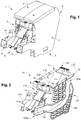
figure 5 est une vue agrandie du détail A représenté sur lafigure 2 . - La
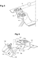
figure 6 est une vue similaire à lafigure 5 , les demi-coques étant en cours d'assemblage. - La
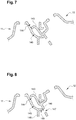
figure 7 est une vue schématique du détail A représenté sur lafigure 2 , dans une première étape d'assemblage de la coque interne. - La
figure 8 est une vue similaire à lafigure 7 , dans une deuxième étape d'assemblage de la coque interne. - La
figure 9 est une vue similaire à lafigure 7 , dans une troisième étape d'assemblage de la coque interne. - La
figure 10 est un diagramme montrant l'évolution comparative de la force de réaction respectivement d'une console centrale équipée d'une coque interne selon l'invention et d'une console centrale équipée d'une coque interne selon une configuration classique lorsque les consoles centrales sont soumises à une force latérale.
- The
figure 1 is a perspective view of a central console formed from an internal shell according to the invention. - The
figure 2 is a perspective view of the inner shell used to form the center console of thefigure 1 . - The
figure 3 is a front view of an inner side wall of one of the half-shells shown on thefigure 2 . - The
figure 4 is an enlarged perspective view of an example of a fastening element allowing the clipping of the half-shells shown on thefigure 2 . - The
figure 5 is an enlarged view of detail A shown infigure 2 . - The
figure 6 is a view similar tofigure 5 , the half-shells being being assembled. - The
figure 7 is a schematic view of detail A shown infigure 2 , in a first assembly step of the internal shell. - The
figure 8 is a view similar tofigure 7 , in a second assembly step of the internal shell. - The
figure 9 is a view similar tofigure 7 , in a third step of assembling the inner shell. - The
figure 10 is a diagram showing the comparative evolution of the reaction force respectively of a central console equipped with an internal shell according to the invention and a central console equipped with an internal shell according to a conventional configuration when the central consoles are subjected to lateral force.
Dans la présente invention, les termes avant et arrière font référence respectivement aux directions avant et arrière du véhicule. Les termes supérieur et inférieur font référence respectivement à des orientations dirigées vers le haut et vers le bas. Les termes intérieur et extérieur font référence respectivement à des orientations dirigées vers l'intérieur et vers l'extérieur du véhicule.In the present invention, the terms front and rear refer respectively to the front and rear directions of the vehicle. The terms upper and lower refer to upward and downward orientations, respectively. The terms interior and exterior refer respectively to orientations directed towards the interior and the exterior of the vehicle.
En référence à la
En référence à la
Comme représenté sur les
De manière à faciliter le montage de la coque interne 10, les demi-coques 11, 12 sont par ailleurs dotées de moyens de connexion complémentaires coopérant ensemble lors de l'assemblage de la coque interne 10 de manière à former une articulation de type charmière au niveau d'un bord latéral supérieur avant 14 et d'un bord latéral supérieur arrière 14'. Les moyens de connexion complémentaires mis en oeuvre au niveau du bord latéral supérieur avant 14 sont illustrés en détail sur les
Les étapes successives permettant de passer d'une configuration non assemblée de la coque interne 10 à la configuration complètement assemblée de ladite coque 10 sont représentées sur les
En référence à la
En référence à la
En référence à la
En référence à la
Claims (11)
Applications Claiming Priority (1)
| Application Number | Priority Date | Filing Date | Title |
|---|---|---|---|
| FR1906460A FR3097181B1 (en) | 2019-06-17 | 2019-06-17 | Internal shell of a motor vehicle center console |
Publications (2)
| Publication Number | Publication Date |
|---|---|
| EP3753788A1 true EP3753788A1 (en) | 2020-12-23 |
| EP3753788B1 EP3753788B1 (en) | 2021-09-08 |
Family
ID=68138427
Family Applications (1)
| Application Number | Title | Priority Date | Filing Date |
|---|---|---|---|
| EP20175805.9A Active EP3753788B1 (en) | 2019-06-17 | 2020-05-20 | Internal shell of a central console of a motor vehicle |
Country Status (3)
| Country | Link |
|---|---|
| EP (1) | EP3753788B1 (en) |
| ES (1) | ES2902583T3 (en) |
| FR (1) | FR3097181B1 (en) |
Citations (3)
| Publication number | Priority date | Publication date | Assignee | Title |
|---|---|---|---|---|
| FR2665405A3 (en) * | 1990-08-02 | 1992-02-07 | Meta System Spa | ARTICULATED HOUSING FOR ANTI-THEFT. |
| WO2000021793A1 (en) * | 1998-10-14 | 2000-04-20 | Magna Seating Systems Inc. | Center console assembly |
| US20140300124A1 (en) * | 2013-04-08 | 2014-10-09 | GM Global Technology Operations LLC | Adaptable bin with folding secondary bin |
-
2019
- 2019-06-17 FR FR1906460A patent/FR3097181B1/en not_active Expired - Fee Related
-
2020
- 2020-05-20 EP EP20175805.9A patent/EP3753788B1/en active Active
- 2020-05-20 ES ES20175805T patent/ES2902583T3/en active Active
Patent Citations (3)
| Publication number | Priority date | Publication date | Assignee | Title |
|---|---|---|---|---|
| FR2665405A3 (en) * | 1990-08-02 | 1992-02-07 | Meta System Spa | ARTICULATED HOUSING FOR ANTI-THEFT. |
| WO2000021793A1 (en) * | 1998-10-14 | 2000-04-20 | Magna Seating Systems Inc. | Center console assembly |
| US20140300124A1 (en) * | 2013-04-08 | 2014-10-09 | GM Global Technology Operations LLC | Adaptable bin with folding secondary bin |
Also Published As
| Publication number | Publication date |
|---|---|
| ES2902583T3 (en) | 2022-03-29 |
| EP3753788B1 (en) | 2021-09-08 |
| FR3097181B1 (en) | 2022-01-07 |
| FR3097181A1 (en) | 2020-12-18 |
Similar Documents
| Publication | Publication Date | Title |
|---|---|---|
| EP2750935B1 (en) | Vehicle safety device | |
| FR3040681A1 (en) | AUTOMOTIVE EQUIPMENT FOR EQUIPPING A MOTOR VEHICLE AND A CAR ASSEMBLY COMPRISING SUCH AN AUTOMOTIVE EQUIPMENT | |
| FR2979865A1 (en) | INSTALLATION AND RETENTION OF SLIDING ARMOR COMPONENTS | |
| FR2883810A1 (en) | Guide rail assembly for motor vehicle seat, has cross piece carrying electrical motor which drives mechanisms by flexible connections having rotating shafts surrounded by flexible sheath integrated with crosspiece without clearance | |
| FR3007349A1 (en) | SAFETY DEVICE FOR VEHICLE | |
| EP3753788B1 (en) | Internal shell of a central console of a motor vehicle | |
| EP1666309A1 (en) | Fastening clip for vehicle liner, combination of clip and liner and vehicle having same | |
| EP2384925B1 (en) | Seat backrest body made of blow-molded plastic, comprising an anchoring device for secure attachment of a child safety seat | |
| WO2020120731A1 (en) | Vehicle steering wheel | |
| EP1712429A2 (en) | Interior car equipment device and its assembly method | |
| FR2896742A1 (en) | Motor vehicle central console with stowage compartment incorporates ventilation ducts formed by folded internal panels | |
| EP1718100B1 (en) | Loudspeaker's grille arrangement | |
| FR2756787A1 (en) | DEVICE FOR MOUNTING AN ARMREST ON A COLUMN | |
| EP2183149B1 (en) | Rear-wing liner of a motor vehicle, and motor vehicle comprising at least one such liner | |
| WO2011095746A2 (en) | Set of equipment for a motor vehicle and associated assembly method | |
| EP4065424A1 (en) | Deflector for a curtain airbag | |
| EP1734208B1 (en) | Vehicle trim element arrangement forming gripping handle | |
| FR2758783A1 (en) | Automobile front driving compartment dashboard assembly | |
| EP2066514B1 (en) | Automotive vehicle door arragement for the link between two profiles | |
| WO2000064692A2 (en) | Device for fixing a rigid object on a support, especially a condenser on a cooling radiator | |
| WO2023110519A1 (en) | Opening panel for vehicle comprising a sealing means | |
| EP3778284A1 (en) | Attachment assembly for attaching at least two parts together | |
| EP2000341B1 (en) | Assembly for an automobile vehicle door | |
| FR2982558A3 (en) | Arrangement for arranging storage unit of male element on trilling element of rear quarter panel and/or roof of car, has immobilization unit to immobilize male element formed from material with wall of trimming element of panel and/or roof | |
| EP1736366B1 (en) | Arrangement for mounting a trim panel to a body panel of a motor vehicle and corresponding mounting piece |
Legal Events
| Date | Code | Title | Description |
|---|---|---|---|
| PUAI | Public reference made under article 153(3) epc to a published international application that has entered the european phase |
Free format text: ORIGINAL CODE: 0009012 |
|
| STAA | Information on the status of an ep patent application or granted ep patent |
Free format text: STATUS: THE APPLICATION HAS BEEN PUBLISHED |
|
| AK | Designated contracting states |
Kind code of ref document: A1 Designated state(s): AL AT BE BG CH CY CZ DE DK EE ES FI FR GB GR HR HU IE IS IT LI LT LU LV MC MK MT NL NO PL PT RO RS SE SI SK SM TR |
|
| AX | Request for extension of the european patent |
Extension state: BA ME |
|
| STAA | Information on the status of an ep patent application or granted ep patent |
Free format text: STATUS: REQUEST FOR EXAMINATION WAS MADE |
|
| 17P | Request for examination filed |
Effective date: 20210127 |
|
| RBV | Designated contracting states (corrected) |
Designated state(s): AL AT BE BG CH CY CZ DE DK EE ES FI FR GB GR HR HU IE IS IT LI LT LU LV MC MK MT NL NO PL PT RO RS SE SI SK SM TR |
|
| GRAJ | Information related to disapproval of communication of intention to grant by the applicant or resumption of examination proceedings by the epo deleted |
Free format text: ORIGINAL CODE: EPIDOSDIGR1 |
|
| STAA | Information on the status of an ep patent application or granted ep patent |
Free format text: STATUS: GRANT OF PATENT IS INTENDED |
|
| GRAP | Despatch of communication of intention to grant a patent |
Free format text: ORIGINAL CODE: EPIDOSNIGR1 |
|
| INTG | Intention to grant announced |
Effective date: 20210511 |
|
| GRAS | Grant fee paid |
Free format text: ORIGINAL CODE: EPIDOSNIGR3 |
|
| GRAA | (expected) grant |
Free format text: ORIGINAL CODE: 0009210 |
|
| STAA | Information on the status of an ep patent application or granted ep patent |
Free format text: STATUS: THE PATENT HAS BEEN GRANTED |
|
| AK | Designated contracting states |
Kind code of ref document: B1 Designated state(s): AL AT BE BG CH CY CZ DE DK EE ES FI FR GB GR HR HU IE IS IT LI LT LU LV MC MK MT NL NO PL PT RO RS SE SI SK SM TR |
|
| REG | Reference to a national code |
Ref country code: GB Ref legal event code: FG4D Free format text: NOT ENGLISH |
|
| REG | Reference to a national code |
Ref country code: CH Ref legal event code: EP Ref country code: AT Ref legal event code: REF Ref document number: 1428314 Country of ref document: AT Kind code of ref document: T Effective date: 20210915 |
|
| REG | Reference to a national code |
Ref country code: IE Ref legal event code: FG4D Free format text: LANGUAGE OF EP DOCUMENT: FRENCH |
|
| REG | Reference to a national code |
Ref country code: DE Ref legal event code: R096 Ref document number: 602020000516 Country of ref document: DE |
|
| REG | Reference to a national code |
Ref country code: LT Ref legal event code: MG9D |
|
| REG | Reference to a national code |
Ref country code: NL Ref legal event code: MP Effective date: 20210908 Ref country code: SK Ref legal event code: T3 Ref document number: E 38533 Country of ref document: SK |
|
| PG25 | Lapsed in a contracting state [announced via postgrant information from national office to epo] |
Ref country code: BG Free format text: LAPSE BECAUSE OF FAILURE TO SUBMIT A TRANSLATION OF THE DESCRIPTION OR TO PAY THE FEE WITHIN THE PRESCRIBED TIME-LIMIT Effective date: 20211208 Ref country code: LT Free format text: LAPSE BECAUSE OF FAILURE TO SUBMIT A TRANSLATION OF THE DESCRIPTION OR TO PAY THE FEE WITHIN THE PRESCRIBED TIME-LIMIT Effective date: 20210908 Ref country code: HR Free format text: LAPSE BECAUSE OF FAILURE TO SUBMIT A TRANSLATION OF THE DESCRIPTION OR TO PAY THE FEE WITHIN THE PRESCRIBED TIME-LIMIT Effective date: 20210908 Ref country code: FI Free format text: LAPSE BECAUSE OF FAILURE TO SUBMIT A TRANSLATION OF THE DESCRIPTION OR TO PAY THE FEE WITHIN THE PRESCRIBED TIME-LIMIT Effective date: 20210908 Ref country code: NO Free format text: LAPSE BECAUSE OF FAILURE TO SUBMIT A TRANSLATION OF THE DESCRIPTION OR TO PAY THE FEE WITHIN THE PRESCRIBED TIME-LIMIT Effective date: 20211208 Ref country code: RS Free format text: LAPSE BECAUSE OF FAILURE TO SUBMIT A TRANSLATION OF THE DESCRIPTION OR TO PAY THE FEE WITHIN THE PRESCRIBED TIME-LIMIT Effective date: 20210908 Ref country code: SE Free format text: LAPSE BECAUSE OF FAILURE TO SUBMIT A TRANSLATION OF THE DESCRIPTION OR TO PAY THE FEE WITHIN THE PRESCRIBED TIME-LIMIT Effective date: 20210908 |
|
| REG | Reference to a national code |
Ref country code: AT Ref legal event code: MK05 Ref document number: 1428314 Country of ref document: AT Kind code of ref document: T Effective date: 20210908 |
|
| PG25 | Lapsed in a contracting state [announced via postgrant information from national office to epo] |
Ref country code: LV Free format text: LAPSE BECAUSE OF FAILURE TO SUBMIT A TRANSLATION OF THE DESCRIPTION OR TO PAY THE FEE WITHIN THE PRESCRIBED TIME-LIMIT Effective date: 20210908 Ref country code: GR Free format text: LAPSE BECAUSE OF FAILURE TO SUBMIT A TRANSLATION OF THE DESCRIPTION OR TO PAY THE FEE WITHIN THE PRESCRIBED TIME-LIMIT Effective date: 20211209 |
|
| REG | Reference to a national code |
Ref country code: ES Ref legal event code: FG2A Ref document number: 2902583 Country of ref document: ES Kind code of ref document: T3 Effective date: 20220329 |
|
| PG25 | Lapsed in a contracting state [announced via postgrant information from national office to epo] |
Ref country code: AT Free format text: LAPSE BECAUSE OF FAILURE TO SUBMIT A TRANSLATION OF THE DESCRIPTION OR TO PAY THE FEE WITHIN THE PRESCRIBED TIME-LIMIT Effective date: 20210908 |
|
| PG25 | Lapsed in a contracting state [announced via postgrant information from national office to epo] |
Ref country code: IS Free format text: LAPSE BECAUSE OF FAILURE TO SUBMIT A TRANSLATION OF THE DESCRIPTION OR TO PAY THE FEE WITHIN THE PRESCRIBED TIME-LIMIT Effective date: 20220108 Ref country code: SM Free format text: LAPSE BECAUSE OF FAILURE TO SUBMIT A TRANSLATION OF THE DESCRIPTION OR TO PAY THE FEE WITHIN THE PRESCRIBED TIME-LIMIT Effective date: 20210908 Ref country code: RO Free format text: LAPSE BECAUSE OF FAILURE TO SUBMIT A TRANSLATION OF THE DESCRIPTION OR TO PAY THE FEE WITHIN THE PRESCRIBED TIME-LIMIT Effective date: 20210908 Ref country code: PT Free format text: LAPSE BECAUSE OF FAILURE TO SUBMIT A TRANSLATION OF THE DESCRIPTION OR TO PAY THE FEE WITHIN THE PRESCRIBED TIME-LIMIT Effective date: 20220110 Ref country code: PL Free format text: LAPSE BECAUSE OF FAILURE TO SUBMIT A TRANSLATION OF THE DESCRIPTION OR TO PAY THE FEE WITHIN THE PRESCRIBED TIME-LIMIT Effective date: 20210908 Ref country code: NL Free format text: LAPSE BECAUSE OF FAILURE TO SUBMIT A TRANSLATION OF THE DESCRIPTION OR TO PAY THE FEE WITHIN THE PRESCRIBED TIME-LIMIT Effective date: 20210908 Ref country code: EE Free format text: LAPSE BECAUSE OF FAILURE TO SUBMIT A TRANSLATION OF THE DESCRIPTION OR TO PAY THE FEE WITHIN THE PRESCRIBED TIME-LIMIT Effective date: 20210908 Ref country code: AL Free format text: LAPSE BECAUSE OF FAILURE TO SUBMIT A TRANSLATION OF THE DESCRIPTION OR TO PAY THE FEE WITHIN THE PRESCRIBED TIME-LIMIT Effective date: 20210908 |
|
| REG | Reference to a national code |
Ref country code: DE Ref legal event code: R097 Ref document number: 602020000516 Country of ref document: DE |
|
| PLBE | No opposition filed within time limit |
Free format text: ORIGINAL CODE: 0009261 |
|
| STAA | Information on the status of an ep patent application or granted ep patent |
Free format text: STATUS: NO OPPOSITION FILED WITHIN TIME LIMIT |
|
| PG25 | Lapsed in a contracting state [announced via postgrant information from national office to epo] |
Ref country code: DK Free format text: LAPSE BECAUSE OF FAILURE TO SUBMIT A TRANSLATION OF THE DESCRIPTION OR TO PAY THE FEE WITHIN THE PRESCRIBED TIME-LIMIT Effective date: 20210908 |
|
| 26N | No opposition filed |
Effective date: 20220609 |
|
| REG | Reference to a national code |
Ref country code: BE Ref legal event code: MM Effective date: 20220531 |
|
| PG25 | Lapsed in a contracting state [announced via postgrant information from national office to epo] |
Ref country code: MC Free format text: LAPSE BECAUSE OF FAILURE TO SUBMIT A TRANSLATION OF THE DESCRIPTION OR TO PAY THE FEE WITHIN THE PRESCRIBED TIME-LIMIT Effective date: 20210908 Ref country code: LU Free format text: LAPSE BECAUSE OF NON-PAYMENT OF DUE FEES Effective date: 20220520 |
|
| PG25 | Lapsed in a contracting state [announced via postgrant information from national office to epo] |
Ref country code: IE Free format text: LAPSE BECAUSE OF NON-PAYMENT OF DUE FEES Effective date: 20220520 |
|
| PG25 | Lapsed in a contracting state [announced via postgrant information from national office to epo] |
Ref country code: BE Free format text: LAPSE BECAUSE OF NON-PAYMENT OF DUE FEES Effective date: 20220531 |
|
| REG | Reference to a national code |
Ref country code: ES Ref legal event code: FD2A Effective date: 20230626 |
|
| PG25 | Lapsed in a contracting state [announced via postgrant information from national office to epo] |
Ref country code: ES Free format text: LAPSE BECAUSE OF NON-PAYMENT OF DUE FEES Effective date: 20220521 |
|
| PGFP | Annual fee paid to national office [announced via postgrant information from national office to epo] |
Ref country code: IT Payment date: 20230531 Year of fee payment: 4 Ref country code: FR Payment date: 20230428 Year of fee payment: 4 Ref country code: DE Payment date: 20230517 Year of fee payment: 4 Ref country code: CZ Payment date: 20230502 Year of fee payment: 4 |
|
| PGFP | Annual fee paid to national office [announced via postgrant information from national office to epo] |
Ref country code: SK Payment date: 20230502 Year of fee payment: 4 |
|
| REG | Reference to a national code |
Ref country code: CH Ref legal event code: PL |
|
| PG25 | Lapsed in a contracting state [announced via postgrant information from national office to epo] |
Ref country code: LI Free format text: LAPSE BECAUSE OF NON-PAYMENT OF DUE FEES Effective date: 20230531 Ref country code: CH Free format text: LAPSE BECAUSE OF NON-PAYMENT OF DUE FEES Effective date: 20230531 |
|
| PG25 | Lapsed in a contracting state [announced via postgrant information from national office to epo] |
Ref country code: MK Free format text: LAPSE BECAUSE OF FAILURE TO SUBMIT A TRANSLATION OF THE DESCRIPTION OR TO PAY THE FEE WITHIN THE PRESCRIBED TIME-LIMIT Effective date: 20210908 Ref country code: CY Free format text: LAPSE BECAUSE OF FAILURE TO SUBMIT A TRANSLATION OF THE DESCRIPTION OR TO PAY THE FEE WITHIN THE PRESCRIBED TIME-LIMIT Effective date: 20210908 |