EP3753553B1 - 3d-drucker - Google Patents
3d-drucker Download PDFInfo
- Publication number
- EP3753553B1 EP3753553B1 EP20178209.1A EP20178209A EP3753553B1 EP 3753553 B1 EP3753553 B1 EP 3753553B1 EP 20178209 A EP20178209 A EP 20178209A EP 3753553 B1 EP3753553 B1 EP 3753553B1
- Authority
- EP
- European Patent Office
- Prior art keywords
- syringe
- support
- block
- axis
- Prior art date
- Legal status (The legal status is an assumption and is not a legal conclusion. Google has not performed a legal analysis and makes no representation as to the accuracy of the status listed.)
- Active
Links
Images


Classifications
-
- B—PERFORMING OPERATIONS; TRANSPORTING
- B29—WORKING OF PLASTICS; WORKING OF SUBSTANCES IN A PLASTIC STATE IN GENERAL
- B29C—SHAPING OR JOINING OF PLASTICS; SHAPING OF MATERIAL IN A PLASTIC STATE, NOT OTHERWISE PROVIDED FOR; AFTER-TREATMENT OF THE SHAPED PRODUCTS, e.g. REPAIRING
- B29C64/00—Additive manufacturing, i.e. manufacturing of three-dimensional [3D] objects by additive deposition, additive agglomeration or additive layering, e.g. by 3D printing, stereolithography or selective laser sintering
- B29C64/10—Processes of additive manufacturing
- B29C64/171—Processes of additive manufacturing specially adapted for manufacturing multiple 3D objects
- B29C64/176—Sequentially
-
- A—HUMAN NECESSITIES
- A23—FOODS OR FOODSTUFFS; TREATMENT THEREOF, NOT COVERED BY OTHER CLASSES
- A23P—SHAPING OR WORKING OF FOODSTUFFS, NOT FULLY COVERED BY A SINGLE OTHER SUBCLASS
- A23P30/00—Shaping or working of foodstuffs characterised by the process or apparatus
- A23P30/20—Extruding
-
- A—HUMAN NECESSITIES
- A61—MEDICAL OR VETERINARY SCIENCE; HYGIENE
- A61J—CONTAINERS SPECIALLY ADAPTED FOR MEDICAL OR PHARMACEUTICAL PURPOSES; DEVICES OR METHODS SPECIALLY ADAPTED FOR BRINGING PHARMACEUTICAL PRODUCTS INTO PARTICULAR PHYSICAL OR ADMINISTERING FORMS; DEVICES FOR ADMINISTERING FOOD OR MEDICINES ORALLY; BABY COMFORTERS; DEVICES FOR RECEIVING SPITTLE
- A61J3/00—Devices or methods specially adapted for bringing pharmaceutical products into particular physical or administering forms
-
- A—HUMAN NECESSITIES
- A61—MEDICAL OR VETERINARY SCIENCE; HYGIENE
- A61K—PREPARATIONS FOR MEDICAL, DENTAL OR TOILETRY PURPOSES
- A61K9/00—Medicinal preparations characterised by special physical form
- A61K9/20—Pills, tablets, discs, rods
- A61K9/2095—Tabletting processes; Dosage units made by direct compression of powders or specially processed granules, by eliminating solvents, by melt-extrusion, by injection molding, by 3D printing
-
- B—PERFORMING OPERATIONS; TRANSPORTING
- B29—WORKING OF PLASTICS; WORKING OF SUBSTANCES IN A PLASTIC STATE IN GENERAL
- B29C—SHAPING OR JOINING OF PLASTICS; SHAPING OF MATERIAL IN A PLASTIC STATE, NOT OTHERWISE PROVIDED FOR; AFTER-TREATMENT OF THE SHAPED PRODUCTS, e.g. REPAIRING
- B29C64/00—Additive manufacturing, i.e. manufacturing of three-dimensional [3D] objects by additive deposition, additive agglomeration or additive layering, e.g. by 3D printing, stereolithography or selective laser sintering
- B29C64/10—Processes of additive manufacturing
- B29C64/106—Processes of additive manufacturing using only liquids or viscous materials, e.g. depositing a continuous bead of viscous material
- B29C64/118—Processes of additive manufacturing using only liquids or viscous materials, e.g. depositing a continuous bead of viscous material using filamentary material being melted, e.g. fused deposition modelling [FDM]
-
- B—PERFORMING OPERATIONS; TRANSPORTING
- B29—WORKING OF PLASTICS; WORKING OF SUBSTANCES IN A PLASTIC STATE IN GENERAL
- B29C—SHAPING OR JOINING OF PLASTICS; SHAPING OF MATERIAL IN A PLASTIC STATE, NOT OTHERWISE PROVIDED FOR; AFTER-TREATMENT OF THE SHAPED PRODUCTS, e.g. REPAIRING
- B29C64/00—Additive manufacturing, i.e. manufacturing of three-dimensional [3D] objects by additive deposition, additive agglomeration or additive layering, e.g. by 3D printing, stereolithography or selective laser sintering
- B29C64/10—Processes of additive manufacturing
- B29C64/171—Processes of additive manufacturing specially adapted for manufacturing multiple 3D objects
- B29C64/182—Processes of additive manufacturing specially adapted for manufacturing multiple 3D objects in parallel batches
-
- B—PERFORMING OPERATIONS; TRANSPORTING
- B29—WORKING OF PLASTICS; WORKING OF SUBSTANCES IN A PLASTIC STATE IN GENERAL
- B29C—SHAPING OR JOINING OF PLASTICS; SHAPING OF MATERIAL IN A PLASTIC STATE, NOT OTHERWISE PROVIDED FOR; AFTER-TREATMENT OF THE SHAPED PRODUCTS, e.g. REPAIRING
- B29C64/00—Additive manufacturing, i.e. manufacturing of three-dimensional [3D] objects by additive deposition, additive agglomeration or additive layering, e.g. by 3D printing, stereolithography or selective laser sintering
- B29C64/20—Apparatus for additive manufacturing; Details thereof or accessories therefor
- B29C64/205—Means for applying layers
- B29C64/209—Heads; Nozzles
-
- B—PERFORMING OPERATIONS; TRANSPORTING
- B29—WORKING OF PLASTICS; WORKING OF SUBSTANCES IN A PLASTIC STATE IN GENERAL
- B29C—SHAPING OR JOINING OF PLASTICS; SHAPING OF MATERIAL IN A PLASTIC STATE, NOT OTHERWISE PROVIDED FOR; AFTER-TREATMENT OF THE SHAPED PRODUCTS, e.g. REPAIRING
- B29C64/00—Additive manufacturing, i.e. manufacturing of three-dimensional [3D] objects by additive deposition, additive agglomeration or additive layering, e.g. by 3D printing, stereolithography or selective laser sintering
- B29C64/20—Apparatus for additive manufacturing; Details thereof or accessories therefor
- B29C64/227—Driving means
- B29C64/241—Driving means for rotary motion
-
- B—PERFORMING OPERATIONS; TRANSPORTING
- B29—WORKING OF PLASTICS; WORKING OF SUBSTANCES IN A PLASTIC STATE IN GENERAL
- B29C—SHAPING OR JOINING OF PLASTICS; SHAPING OF MATERIAL IN A PLASTIC STATE, NOT OTHERWISE PROVIDED FOR; AFTER-TREATMENT OF THE SHAPED PRODUCTS, e.g. REPAIRING
- B29C64/00—Additive manufacturing, i.e. manufacturing of three-dimensional [3D] objects by additive deposition, additive agglomeration or additive layering, e.g. by 3D printing, stereolithography or selective laser sintering
- B29C64/20—Apparatus for additive manufacturing; Details thereof or accessories therefor
- B29C64/255—Enclosures for the building material, e.g. powder containers
- B29C64/259—Interchangeable
-
- B—PERFORMING OPERATIONS; TRANSPORTING
- B29—WORKING OF PLASTICS; WORKING OF SUBSTANCES IN A PLASTIC STATE IN GENERAL
- B29C—SHAPING OR JOINING OF PLASTICS; SHAPING OF MATERIAL IN A PLASTIC STATE, NOT OTHERWISE PROVIDED FOR; AFTER-TREATMENT OF THE SHAPED PRODUCTS, e.g. REPAIRING
- B29C64/00—Additive manufacturing, i.e. manufacturing of three-dimensional [3D] objects by additive deposition, additive agglomeration or additive layering, e.g. by 3D printing, stereolithography or selective laser sintering
- B29C64/20—Apparatus for additive manufacturing; Details thereof or accessories therefor
- B29C64/295—Heating elements
-
- B—PERFORMING OPERATIONS; TRANSPORTING
- B29—WORKING OF PLASTICS; WORKING OF SUBSTANCES IN A PLASTIC STATE IN GENERAL
- B29C—SHAPING OR JOINING OF PLASTICS; SHAPING OF MATERIAL IN A PLASTIC STATE, NOT OTHERWISE PROVIDED FOR; AFTER-TREATMENT OF THE SHAPED PRODUCTS, e.g. REPAIRING
- B29C64/00—Additive manufacturing, i.e. manufacturing of three-dimensional [3D] objects by additive deposition, additive agglomeration or additive layering, e.g. by 3D printing, stereolithography or selective laser sintering
- B29C64/30—Auxiliary operations or equipment
- B29C64/307—Handling of material to be used in additive manufacturing
- B29C64/321—Feeding
-
- B—PERFORMING OPERATIONS; TRANSPORTING
- B33—ADDITIVE MANUFACTURING TECHNOLOGY
- B33Y—ADDITIVE MANUFACTURING, i.e. MANUFACTURING OF THREE-DIMENSIONAL [3-D] OBJECTS BY ADDITIVE DEPOSITION, ADDITIVE AGGLOMERATION OR ADDITIVE LAYERING, e.g. BY 3-D PRINTING, STEREOLITHOGRAPHY OR SELECTIVE LASER SINTERING
- B33Y10/00—Processes of additive manufacturing
-
- B—PERFORMING OPERATIONS; TRANSPORTING
- B33—ADDITIVE MANUFACTURING TECHNOLOGY
- B33Y—ADDITIVE MANUFACTURING, i.e. MANUFACTURING OF THREE-DIMENSIONAL [3-D] OBJECTS BY ADDITIVE DEPOSITION, ADDITIVE AGGLOMERATION OR ADDITIVE LAYERING, e.g. BY 3-D PRINTING, STEREOLITHOGRAPHY OR SELECTIVE LASER SINTERING
- B33Y30/00—Apparatus for additive manufacturing; Details thereof or accessories therefor
-
- B—PERFORMING OPERATIONS; TRANSPORTING
- B33—ADDITIVE MANUFACTURING TECHNOLOGY
- B33Y—ADDITIVE MANUFACTURING, i.e. MANUFACTURING OF THREE-DIMENSIONAL [3-D] OBJECTS BY ADDITIVE DEPOSITION, ADDITIVE AGGLOMERATION OR ADDITIVE LAYERING, e.g. BY 3-D PRINTING, STEREOLITHOGRAPHY OR SELECTIVE LASER SINTERING
- B33Y80/00—Products made by additive manufacturing
-
- A—HUMAN NECESSITIES
- A61—MEDICAL OR VETERINARY SCIENCE; HYGIENE
- A61J—CONTAINERS SPECIALLY ADAPTED FOR MEDICAL OR PHARMACEUTICAL PURPOSES; DEVICES OR METHODS SPECIALLY ADAPTED FOR BRINGING PHARMACEUTICAL PRODUCTS INTO PARTICULAR PHYSICAL OR ADMINISTERING FORMS; DEVICES FOR ADMINISTERING FOOD OR MEDICINES ORALLY; BABY COMFORTERS; DEVICES FOR RECEIVING SPITTLE
- A61J2200/00—General characteristics or adaptations
- A61J2200/20—Extrusion means, e.g. for producing pharmaceutical forms
-
- A—HUMAN NECESSITIES
- A61—MEDICAL OR VETERINARY SCIENCE; HYGIENE
- A61J—CONTAINERS SPECIALLY ADAPTED FOR MEDICAL OR PHARMACEUTICAL PURPOSES; DEVICES OR METHODS SPECIALLY ADAPTED FOR BRINGING PHARMACEUTICAL PRODUCTS INTO PARTICULAR PHYSICAL OR ADMINISTERING FORMS; DEVICES FOR ADMINISTERING FOOD OR MEDICINES ORALLY; BABY COMFORTERS; DEVICES FOR RECEIVING SPITTLE
- A61J2200/00—General characteristics or adaptations
- A61J2200/40—Heating or cooling means; Combinations thereof
- A61J2200/42—Heating means
Definitions
- Machines exist for dispensing pharmaceutical products. However, existing machines produce volumes of identical products and rely on dispensing agents, such as pharmacists, to arrange pharmaceutical products for individual consumers. A device for reducing the burden placed upon dispensing agents is therefore desirable.
- US 2018/007949 A1 discloses a cartridge assembly, a cartridge unit, a food forming module, and a cooking apparatus capable of using three-dimensional (3D) printing technology to form and cook food.
- US 2018/281280 A1 discloses a three-dimensional bioprinter for printing and/or patterning a single type or multiple types of cells into different geometrical arrangements and other three-dimensional structures, such as tissues.
- the bioprinter comprises multiple heads that can each be loaded with a different cartridge containing a biomaterial or biological material such as cells in a solution or cells in a hydrogel.
- the 3D printer according to the first aspect of the invention is arranged to print a plurality of consumable items such as pharmaceutical or healthcare supplements in parallel.
- the print head positions the dispensers such that the printing axes of the dispensers are arranged in an equidistant manner around a circular path to define a regular polygon.
- the print bed has corresponding print locations.
- the translation device enables the nozzle of each dispenser to print a layer of a consumable item in a shape at a respective print location.
- the rotation device can be operated to index the print head or the print bed to place the nozzles in registration with another print location in order to build up a second layer of each consumable item on top of the first layer. This process can be repeated a number of times to quickly produce a plurality of multi-component consumable items.
- the dispensers can dispense quick set material liquid.
- the print zone can comprise a plate and the rotation device can be mechanically coupled to the plate to rotate the plate about the second Z axis.
- the rotation device can be arranged to rotate the part of the print bed upon which the print head is arranged to print. This can be advantageous in that the print zone plate can be significantly lighter than the liquid dispensers and the portion of the print head which carries them, meaning that smaller, cheaper motors and the like can be utilised, bringing energy and heat efficiencies.
- the translation device can be arranged to move the print bed relative to the print head along the Z axis. This enables the distance between the tips of the dispenser nozzles and the print locations on the print bed to be increased as layers of the consumable items are added, enabling the nozzles to be continually close to the top surface of a consumable item as it is built up.
- Each dispenser can be a syringe arranged to be mounted in or on the print head, the print head being arranged to support the plurality of syringes. This enables ubiquitous syringes such as food or medicine grade stainless steel syringes to be used for the printing process.
- the print head can comprise: a block having a plurality of block apertures extending through the block; and a syringe support arranged to receive and hold the syringes to define the regular polygon, the syringe support being removably coupled to the block.
- the block can comprise heating means operable to heat the liquid in the syringes.
- the heat block can be used to heat the liquid in the dispensers to aid in it being extruded by the actuator device during the dispensing cycles.
- the block can have a thickness in the Z axis which encompasses at least half of the length of the body of the syringes to provide a large region of thermal coupling.
- the heating means can comprise resistive electrical wiring or hot water conduits embedded in a metal block.
- the syringe support can comprise: a first support plate having a plurality of support apertures, each support aperture being arranged to receive a syringe and being sized such at least some of the body of the syringe can pass through the support aperture but a radially enlarged flange of the syringe body cannot pass through the support aperture; a second support plate having a plurality of support apertures, each support aperture being arranged to receive a syringe and being sized such at least some of the body of the syringe can pass through the support aperture but a radially enlarged flange of the syringe body cannot pass through the support aperture, the support apertures being arranged to define the regular polygon; and coupling formations arranged to enable the first support plate to be coupled to the block with the second support plate being situated between the block and the first support plate.
- the coupling formations can comprise regions of ferromagnetic material and the block comprises a plurality of electromagnets situated to align with the coupling regions when the syringe support is situated on the block and operable to magnetically couple the syringe support to the block.
- the coupling formations can comprise discs which extend from a lower face of the first plate by a distance which places the free axial faces of the discs in registration with the lower surface of the second plate when the plates are pressed together with the syringe flanges between them.
- the actuator device can comprise: a drive plate having a drive face with plurality of syringe plunger locations arranged in the regular polygon and a pair of parallel support rails defining a channel between them and having flanged sections spaced from the first plate and extending towards one another, the plurality of syringe plunger locations being defined between the support rails; first and second retention plates, each retention plate including a plurality of retention slots that extend into the retention plate from a first edge and have arcuate end faces which, when the first and second retention plates are inserted into opposite end of the channel, with the syringe plungers located at the syringe plunger locations, overlap the syringe plungers to grasp the syringe plungers; and one or more linear actuators coupled between the drive plate and the block to linearly move the drive plate towards the block to dispense liquid from the syringes.
- This provides a device via which a plurality of syringes located in a sy
- the print bed can comprise a plurality of print zones.
- the translation device can be utilised to move the print bed along the X axis once a first set of consumable items have been printed at the first print zone and the process can be repeated to print one or more further sets of consumable items at one or more further print zones on the print bed. This can enable a greater number of consumable items to be printed in a fast manner without increasing the size, weight and/or complexity of the print head.
- the print head can be arranged to position the nozzles to define a seven sided polygon and each print zone positions the print locations to define a seven sided polygon.
- the print bed can consists of four print zones disposed in a linear arrangement along the print bed, with the axis of each print zone intersecting a longitudinal axis of the print bed. This can provide an arrangement particularly well suited to printing pharmaceutical or healthcare supplements.
- the 3D printer can further comprise a controller configured to cause the 3D printer to perform the following steps: with the first Z axis aligned with the second Z axis, operate the actuator device to dispense liquid from each nozzle onto a respective print location: operate the rotation device to cause relative rotation between the print zone and the print head to place each print location in registration with a different one of the nozzles; and operate the actuator device to dispense liquid from each nozzle onto a respective print location.
- This process can be repeated a number of times, preferably by the same number as the number of dispensers such that a multi-layer consumable item can be printed having a component provided by each dispenser.
- the controller can be further configured to cause the 3D printer to perform the following steps: move the print bed in the Z direction away from the print head following each step of operating the actuator device to dispense liquid from each liquid dispenser onto a respective print location by an amount which corresponds to the thickness in the Z axis of the liquid dispensed on the print locations.
- the controller can be further configured to move the print bed in the X and Y directions while operating the actuator device to dispense liquid from each liquid dispenser onto a respective print location to define a closed loop shape.
- the liquid dispensers may be filled with any of the compositions disclosed in WO 2016113318 A1 , WO 201121822 A1 or WO 2017/032689 A1 .
- the liquid dispensers may be filled with a fast-setting composition, optionally a fast-setting gel. This can allow faster rates of manufacture.
- FIGS 1a and 1b show a 3D printer for printing consumable items according to an embodiment of the invention generally at 10.
- the 3D printer 10 is arranged to print a plurality of consumable items such as pharmaceutical or healthcare supplements in parallel.
- the 3D printer 10 has a print head 12 arranged to position nozzles of a plurality of liquid dispensers to define a regular polygon around a first Z axis Z1.
- the fluid dispensers are syringes arranged to be situated in a downward facing manner on a block 14 within the print head 12.
- the 3D printer 10 has an actuator device 16, which in this embodiment is located within the print head 12, operable to dispense a portion of liquid from each liquid dispenser located within the block 14.
- the 3D printer 10 has a print bed comprising four print zones PZ, each print zone PZ comprising a plurality of print locations PL arranged to define a regular polygon around a respective second Z axis Z2.
- the 3D printer 10 has a translation device operable to move the print bed 18 relative to the print head 12 along X and Y axes.
- the print bed 18 is slidably mounted on a base 20 so as to be movable along the X axis.
- first and second Z axes Z1, Z2 are vertical and may be offset and the X and Y axes are horizontal and may be perpendicular to each other.
- the 3D printer 10 has a rotation device operable to cause relative rotation between the print zone PZ and the print head 12 such that, with the first Z axis Z1 aligned with the second Z axis Z2, the actuator device 16 is operable to dispense liquid from each liquid dispenser onto a respective print location PL and thereafter the rotation device is operable to cause relative rotation between the print zone PZ and the print head 12 to place each print location PL in registration with a different one of the nozzles.
- Figures 2a, 2b and 2c are perspective, top and side view diagrams respectively of the movable portion of the print bed 18 of the 3D printer of Figure 1 .
- the print bed 18 is supported on a base 20, the base having an X motor (not shown) for moving the print bed 18 in the X direction by interaction with an X bearing 30.
- the print bed has a Z motor 26 for moving the print bed 18 in a vertical direction, i.e. along the second Z axis Z2 and a Y motor 28 for moving the print bed 18 along the Y axis.
- the print bed 18 comprises plates 22, which form print zones PZ. In the disclosed embodiment, there are four plates 22 forming four respective print zones PZ, however other numbers of plates 22 and print zones PZ may be used.
- the print zones PZ may be located along a top surface of the print bed 18 and separated along the X axis.
- the respective print zone PZ defined by each plate 22 has a plurality of print locations PL.
- the plates 22 may each be rotationally symmetrical about their respective second Z axis Z2 such that the plates 22 can be rotated and the print locations can change position such that a first print location PL may take the position of a second print location PL when the plate 22 is rotated by a predetermined number of degrees.
- the plates 22 can be rotated in order to move the print locations PL by rotation motors 24.
- the rotation motors 24 are preferably stepper motors, which can provide a high degree of accuracy of rotation.
- Figures 2a and 2b show print zones PZ each having seven print locations PL, other numbers of print locations PL on each print zone are possible.
- the number of print locations PL in each print zone PZ should preferably be the same as the number of syringes supported within the print head 12.
- Figure 3 shows an extrusion system for operating syringes.
- the extrusion system comprises an extrusion plate 34 for pressing on the plungers of syringes and a stabilising plate 36 for securing the plungers of syringes.
- the extrusion plate 34 and the stabilising plate 36 are moveable in a vertical direction along rails 33, which define a channel therebetween.
- Extrusion motors 32a and 32b are arranged to drive the extrusion plate 34 and stabilising plate 36 vertically in order to exert a downward force on the plungers of the syringes such that material is dispensed from the syringes.
- the system may also comprise a heater block 14, which may contain an electrical wire or fluid circulation system and is arranged to heat material within the syringes in order to reduce the viscosity of the material and/or melt the material in order that the material can be more easily dispensed from the syringes and a greater range of materials may be dispensed by using a heater block 14.
- a heater block 14 may contain an electrical wire or fluid circulation system and is arranged to heat material within the syringes in order to reduce the viscosity of the material and/or melt the material in order that the material can be more easily dispensed from the syringes and a greater range of materials may be dispensed by using a heater block 14.
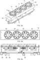
- FIGS 4a and 4b show an arrangement of syringes 42.
- Each syringe has a syringe body 44, which may be filled with an esculent material to be dispensed, a nozzle 48 for controlling dispensation of the material, and a plunger 46, which can be pressed towards the syringe body 44 in order to extrude material from the nozzle 48.
- Each syringe may also have a lug 50 extending from the syringe body 44.
- the lug 50 can be placed between two support plates 38, 40. There may be a first support plate 38 above the lug and a second support plate 40 below the lug.
- the first support plate 38 may have coupling formations 38a for holding the first support plate 38 to a block, such as heating block 14 of the print head 12 or a non-heated block.
- the arrangement of the first and second support plates 38, 40 and the syringes 42 allows the syringes 42 to be held in a stable formation outside the print head 12 so that the syringes 42 can all be inserted quickly and easily at the same time into the print head 12.
- the first support plate 38 may have support apertures 38b sized to be larger than the syringe body 44 and smaller than the lugs 50 and the second support plate 40 may have second support apertures 40b, which may also be sized to be larger than the syringe body 44 and smaller than the lugs 50. This allows the syringes 42 to be inserted through the support apertures 38b, 40b and held in place by the lugs 50 and support plates 38, 40.
- Figure 6 shows the print head 12 with the syringes 42 installed.
- the syringes 42 are installed within the heating block 14 and are held in place by the first support plate 38 and second support plate (not visible in Figure 6 ).
- the coupling formations 38a are coupled to corresponding coupling formations 52 on the heating block 14.
- the coupling formations 38a on the first support place 38 may be ferromagnetic materials and the corresponding coupling formations 52 on the heater block 14 may be magnets, preferably electromagnets.
- the plunger ends of the syringes 42 (not visible in Figure 6 ) are situated under the extrusion plate 34, such that the extrusion plate 34 may move vertically downwards in order to extrude material from the syringes 42.
- FIG. 7 shows a view of the stabilising plate 36 connected to the extrusion plate 34 from underneath. It can be seen that the stabilising plate 36 may be formed as two parts, which may be slid into place along slide rails 35. The stabilising plates 36 may comprise stabilisation slots 36a which may be slid into place in order to hold the plungers 46 of the syringes 42.
- Figures 8 and 9 show how the two parts of the stabilising plate 36 may be slid into place.
- the machine may be operated such that the extrusion plate 34 is operated to push down on the syringes 42 so that all plungers are touching the extruding plate 34 and the stabilising plates 36 may be slid into place to grip onto the plungers 46 while the plungers 46 are all in contact with the extrusion plate 34. This can prevent the plungers 46 from moving away from the extrusion plate 34 and ensure stabilisation of the plungers 46.
- the 3D printer may be operated so that a print zone PZ is positioned underneath the syringes 42, with the first Z axis Z1 collinear with the second Z axis Z2 and the print zone PZ underneath the plungers 46.
- An amount of material may be extruded from the nozzles 48 of the syringes 42 onto the plurality of print locations PL underneath the syringes 42.
- the extrusion may be stopped and the print location can be changed by rotating the plate 22 about the Z axis Z2. The rotation can occur such that after the rotation each print location PL is underneath a different syringe 42.
- a second extrusion step can take place, wherein further material is extruded from each syringe 42 onto a respective print location PL, with each print location PL having a different material from a different syringe 42 deposited onto it between each rotation step.
- This process can be repeated until every print location PL has all necessary material deposited upon it, such as after a complete rotation of the print zone PZ.
- the print bed 18 can be moved in the X direction such that a new print zone PZ and is positioned underneath the syringes 42.
- certain syringes 42 of the arrangement may be absent or may be empty, if the number of different materials required to be deposited does not exactly match the number of print locations PL.
- more than one syringe 42 may contain the same material, it is not essential that every syringe 42 has a different material.
- the syringes 42 may be sterile syringes suitable for use in food or pharmaceutical manufacture and may be filled with pharmaceutical or food compositions for manufacturing food or pharmaceutical supplements, including vitamin and mineral supplements.
- the composition may be solid or may be a gel at room temperature, and may become liquid or a less viscous gel when heated by the heated block 14.
- the print bed 18 can be moved in the Z direction, for example in order to prevent deposited material from touching a syringe nozzle 48.
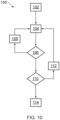
- the flowchart in Figure 10 illustrates a method 100 by which the print head 12 may operate.
- the print head 12 is primed, with the syringes 42 inserted and a print zone PZ situated underneath the syringes 42.
- This may include the print zone PZ being moved into position along the X-axis and may include an alignment check to ensure that each print location PL is aligned with a nozzle 48 of a particular syringe 42.
- step 104 material is deposited from the syringes 42 onto the respective print locations PL by movement of the extrusion plate 34.
- step 106 a check is made as to whether every print location PL within the print zone PZ under the syringes 42 has the required materials deposited upon it. If every print location PL has all of the required materials, then the method moves to step 110, otherwise the method moves to step 108.
- the print zone PZ is rotated so that each print location PL aligns with a different syringe 42 so that a different material can be deposited onto each print location PL.
- a further deposition step 104 can then take place.
- step 110 it is determined whether every print zone PZ on the print bed has had materials deposited upon it, or whether there are more print zones PZ that require printing. If all print zones PZ have been printed, then the method finishes at step 114. Otherwise, the method moves to step 112.
- the print bed is moved in the X direction so that a new print zone PZ is aligned with the syringes 42. This may also include an alignment check to ensure that each print location PL is underneath a syringe 42. Subsequently, a further deposition of material occurs at step 104.
- step 114 the method is finished and the printed products can be removed. At this stage a volume of customised esculent products have been produced.
Landscapes
- Chemical & Material Sciences (AREA)
- Engineering & Computer Science (AREA)
- Materials Engineering (AREA)
- Manufacturing & Machinery (AREA)
- Optics & Photonics (AREA)
- Mechanical Engineering (AREA)
- Physics & Mathematics (AREA)
- Health & Medical Sciences (AREA)
- Life Sciences & Earth Sciences (AREA)
- Veterinary Medicine (AREA)
- Public Health (AREA)
- General Health & Medical Sciences (AREA)
- Animal Behavior & Ethology (AREA)
- Pharmacology & Pharmacy (AREA)
- Medicinal Chemistry (AREA)
- Food Science & Technology (AREA)
- Polymers & Plastics (AREA)
- Epidemiology (AREA)
- Coating Apparatus (AREA)
Claims (14)
- 3D-Drucker zum Drucken von Verbrauchsartikeln, der 3D-Drucker umfassend:eine Vielzahl von Flüssigkeitsspendern (4), wobei jeder Flüssigkeitsspender eine Düse (48) umfasst;ein Druckkopf (12), der angeordnet ist, um die Düsen (48) der Vielzahl von Flüssigkeitsspendern (4) so zu positionieren, dass sie ein regelmäßiges Polygon um eine erste Z-Achse (Z1) definieren;eine Aktuatorvorrichtung (16), die betätigbar ist, um eine Menge an Flüssigkeit aus jedem Flüssigkeitsspender abzugeben;ein Druckbett (18), einen Druckbereich (PZ) umfassend, wobei der Druckbereich eine Vielzahl von Druckpositionen (PL) umfasst, die so angeordnet sind, dass sie ein regelmäßiges Polygon um eine zweite Z-Achse (Z2) definieren; undeine Verfahrvorrichtung (28), die betätigbar ist, um das Druckbett relativ zum Druckkopf entlang der X- und Y-Achsen zu bewegen;eine Rotationsvorrichtung, die betätigbar ist, um eine relative Drehung zwischen dem Druckbereich und dem Druckkopf in der Art zu bewirken, dass wenn die erste Z-Achse auf die zweite Z-Achse ausgerichtet ist, der Aktuator betätigbar ist, um Flüssigkeit aus jedem Flüssigkeitsspender an einer jeweiligen Druckposition abzugeben, und danach die Rotationsvorrichtung betätigbar ist, um eine relative Drehung zwischen dem Druckbereich und dem Druckkopf zu bewirken, um an jeder Druckposition eine andere der Düsen einzurasten; undgekennzeichnet durch einen Controller, der dafür konfiguriert ist, zu bewirken, dass der 3D-Drucker die folgenden Schritte ausführt:wenn die erste Z-Achse auf die zweite Z-Achse ausgerichtet ist, Betätigen der Aktuatorvorrichtung, um Flüssigkeit aus jeder Düse an einer jeweiligen Druckposition abzugeben;dann Betätigen der Rotationsvorrichtung, um eine relative Drehung zwischen dem Druckbereich und dem Druckkopf zu bewirken, um an jeder Druckposition eine andere der Düsen einzurasten; unddann Betätigen der Aktuatorvorrichtung, um Flüssigkeit aus jedem Flüssigkeitsspender an der jeweiligen Druckposition abzugeben.
- 3D-Drucker nach Anspruch 1, wobei der Druckbereich eine Platte (22) umfasst und die Rotationsvorrichtung mechanisch mit der Platte gekoppelt ist, um die Platte um die zweite Z-Achse zu drehen.
- 3D-Drucker nach einem der vorstehenden Ansprüche, wobei die Verfahrvorrichtung betätigbar ist, um das Druckbett relativ zum Druckkopf entlang der Z-Achse zu bewegen.
- 3D-Drucker nach einem der vorstehenden Ansprüche, wobei jeder Spender eine Spritze ist und der Druckkopf dafür ausgelegt ist, die Vielzahl von Spritzen zu tragen.
- 3D-Drucker nach Anspruch 4, wobei der Druckkopf umfasst:einen Block (14) mit einer Vielzahl von Blocköffnungen, die durch den Block verlaufen; undeinen Spritzenträger (38, 40), dafür ausgelegt, die Spritzen aufzunehmen und zu halten, um das regelmäßige Polygon zu definieren, wobei die Spritze abnehmbar mit dem Block gekoppelt ist.
- 3D-Drucker nach Anspruch 5, wobei der Block eine Heizvorrichtung umfasst, die betätigbar ist, um die Flüssigkeit in den Spritzen zu erwärmen.
- 3D-Drucker nach Anspruch 5 oder 6, wobei der Spritzenträger umfasst:eine erste Trägerplatte (38) mit einer Vielzahl von Trägeröffnungen (38b), wobei jede Trägeröffnung angeordnet ist, um eine Spritze aufzunehmen, und von der Größe so ausgelegt ist, dass zumindest ein Teil des Körpers (44) der Spritze durch die Trägeröffnung passt, aber ein radial größerer Flansch (50) des Spritzenkörpers nicht durch die Trägeröffnung passt;eine zweite Trägerplatte (40) mit einer Vielzahl von Trägeröffnungen (40b), wobei jede Trägeröffnung angeordnet ist, um eine Spritze aufzunehmen, und von der Größe so ausgelegt ist, dass zumindest ein Teil des Körpers der Spritze durch die Trägeröffnung passt, aber ein radial größerer Flansch des Spritzenkörpers nicht durch die Trägeröffnung passt,wobei die Trägeröffnungen angeordnet sind, um das regelmäßige Polygon zu definieren; undKopplungsanordnungen (38a), angeordnet, um ein Koppeln der ersten Trägerplatte mit dem Block zu ermöglichen, wobei sich die zweite Trägerplatte zwischen dem Block und der ersten Trägerplatte befindet.
- 3D-Drucker nach Anspruch 7, wobei die Kopplungsanordnungen Regionen aus ferromagnetischem Material umfassen und der Block eine Vielzahl von Elektromagneten (52) umfasst, die zur Ausrichtung auf die Kopplungsregionen platziert sind, wenn der Spritzenträger an dem Block angeordnet ist, und betätigbar sind, um den Spritzenträger magnetisch mit dem Block zu koppeln.
- 3D-Drucker nach einem der Ansprüche 5 bis 8, wobei die Aktuatorvorrichtung umfasst:eine Antriebsplatte (34) mit einer Antriebsfläche mit einer Vielzahl von Spritzenkolbenplätzen, die in dem regelmäßigen Polygon angeordnet sind, und einem Paar paralleler Trägerschienen (35), die zwischen sich einen Kanal definieren, und mit Abschnitten mit Flansch im Abstand zur ersten Platte und zueinander verlaufend, wobei die Vielzahl von Spritzenkolbenplätzen zwischen den Trägerschienen definiert ist;erste und zweite Rückhalteplatten (36), wobei jede Rückhalteplatte eine Vielzahl von Rückhalteschlitzen (36a) umfasst, die sich in die Rückhalteplatte von einer ersten Kante aus erstrecken und gewölbte Endflächen aufweisen, welche, wenn die ersten und zweiten Rückhalteplatten in gegenüberliegende Enden des Kanals eingesetzt werden, während die Spritzenkolben sich an den Spritzenkolbenplätzen befinden, die Spritzenkolben überragen, um die Spritzenkolben zu fassen; undeinen oder mehrere lineare Aktuatoren (32a, 32b), die zwischen der Antriebsplatte und dem Block gekoppelt sind, um die Antriebsplatte linear in Richtung des Blocks zu bewegen, um Flüssigkeit aus den Spritzen abzugeben.
- 3D-Drucker nach einem der vorstehenden Ansprüche, wobei das Druckbett eine Vielzahl von Druckbereichen umfasst.
- 3D-Drucker nach Anspruch 9, wobei der Druckkopf angeordnet ist, um die Düsen so zu positionieren, dass sie ein siebenseitiges Polygon definieren, und jeder Druckbereich die Druckpositionen so anordnet, dass sie ein siebenseitiges Polygon definieren.
- 3D-Drucker nach Anspruch 10, wobei das Druckbett aus vier Druckbereichen besteht, die in einer linearen Anordnung entlang dem Druckbett angeordnet sind, wobei optional die Achse jedes Druckbereichs sich mit einer Längsachse des Druckbetts schneidet.
- 3D-Drucker nach Anspruch 12, wobei der Controller ferner dafür konfiguriert ist, den 3D-Drucker zu veranlassen, die folgenden Schritte auszuführen:Bewegen des Druckbetts in der Z-Richtung, weg vom Druckkopf nach jedem Betätigungsschritt der Aktuatorvorrichtung, um Flüssigkeit aus jedem Flüssigkeitsspender an einer jeweiligen Druckposition abzugeben, in einer Menge, die der Dicke der an den Druckpositionen abgegebenen Flüssigkeit in der Z-Achse entspricht; und/oderBewegen des Druckbetts in der X- und Y-Richtung während der Betätigung der Aktuatorvorrichtung, um Flüssigkeit aus jedem Flüssigkeitsspender an einer jeweiligen Druckposition abzugeben, um eine geschlossene Schleifen-Form zu definieren.
- Verfahren zum gleichzeitigen Herstellen einer Vielzahl von Verbrauchsartikel unter Verwendung des 3D-Druckers nach einem der vorstehenden Ansprüche, das Verfahren umfassend:wenn die erste Z-Achse auf die zweite Z-Achse ausgerichtet ist, Betätigen der Aktuatorvorrichtung, um Flüssigkeit aus jeder Düse an der jeweiligen Druckposition abzugeben;Betätigen der Rotationsvorrichtung, um eine relative Drehung zwischen dem Druckbereich und dem Druckkopf zu bewirken, um an jeder Druckposition eine andere der Düsen einzurasten; undBetätigen der Aktuatorvorrichtung, um Flüssigkeit aus jeder Düse an einer jeweiligen Druckposition abzugeben.
Applications Claiming Priority (1)
| Application Number | Priority Date | Filing Date | Title |
|---|---|---|---|
| GB1908685.9A GB2580194B (en) | 2019-06-18 | 2019-06-18 | 3D Printer |
Publications (3)
| Publication Number | Publication Date |
|---|---|
| EP3753553A1 EP3753553A1 (de) | 2020-12-23 |
| EP3753553B1 true EP3753553B1 (de) | 2025-03-12 |
| EP3753553C0 EP3753553C0 (de) | 2025-03-12 |
Family
ID=67432315
Family Applications (1)
| Application Number | Title | Priority Date | Filing Date |
|---|---|---|---|
| EP20178209.1A Active EP3753553B1 (de) | 2019-06-18 | 2020-06-04 | 3d-drucker |
Country Status (4)
| Country | Link |
|---|---|
| US (1) | US11865776B2 (de) |
| EP (1) | EP3753553B1 (de) |
| CN (1) | CN112089082B (de) |
| GB (1) | GB2580194B (de) |
Families Citing this family (2)
| Publication number | Priority date | Publication date | Assignee | Title |
|---|---|---|---|---|
| GB2590476B (en) * | 2019-12-19 | 2023-02-01 | Softform Ltd | A method and tool for manufacturing a container from a thermoplastic material |
| CA3179941A1 (en) * | 2020-04-14 | 2021-10-21 | Auxilium Biotechnologies Inc. | Dynamic microfabrication through digital photolithography system and methods |
Citations (2)
| Publication number | Priority date | Publication date | Assignee | Title |
|---|---|---|---|---|
| CN105058789A (zh) * | 2015-07-28 | 2015-11-18 | 华中科技大学 | 一种适用于多材质工件的3d打印设备 |
| US20180281280A1 (en) * | 2017-04-04 | 2018-10-04 | Allevi, Inc. | Multi-headed auto-calibrating bioprinter with heads that heat, cool, and crosslink |
Family Cites Families (20)
| Publication number | Priority date | Publication date | Assignee | Title |
|---|---|---|---|---|
| AU2003900180A0 (en) * | 2003-01-16 | 2003-01-30 | Silverbrook Research Pty Ltd | Method and apparatus (dam001) |
| KR20110018261A (ko) | 2009-08-17 | 2011-02-23 | 삼성전자주식회사 | 텍스트 서브타이틀 데이터 처리 방법 및 재생 장치 |
| US10987845B2 (en) * | 2014-02-11 | 2021-04-27 | Structur3D Printing Incorporated | Multi-material extruder and extrusion method for three-dimensional (3D) printing |
| US10065354B2 (en) * | 2014-04-07 | 2018-09-04 | 3D Total Solutions, Inc. | 3D printer system with circular carousel and multiple material delivery systems |
| CN103932369B (zh) * | 2014-04-09 | 2015-08-26 | 西安交通大学 | 一种可控喷注式食品3d打印设备及方法 |
| US9278536B2 (en) * | 2014-07-22 | 2016-03-08 | Xyzprinting, Inc. | Printing head module |
| US9073366B1 (en) * | 2014-07-25 | 2015-07-07 | Xyzprinting, Inc. | Rotational printing head module having muti-cartridge |
| JP5950421B2 (ja) * | 2014-09-30 | 2016-07-13 | 合同会社Genkei | 3dプリンタ用射出ヘッド |
| CA2972674A1 (en) | 2015-01-13 | 2016-07-21 | Katjes Fassin Gmbh. + Co. Kommanditgesellschaft | Production of soft confectionery by means of additive process with a nozzle and soft confectionery obtainable thereby |
| EP3337335B1 (de) | 2015-08-21 | 2023-10-25 | Rem3dy Health Limited | Gelhaltige kartusche zur zubereitung von süsswaren |
| CN105172147A (zh) * | 2015-10-22 | 2015-12-23 | 王黎 | 新型三维打印机 |
| CN105196549B (zh) * | 2015-10-28 | 2017-07-18 | 华中科技大学 | 一种并行多工位式3d打印机 |
| CN105328192B (zh) | 2015-11-13 | 2017-09-29 | 中国地质大学(武汉) | 三维打印机打印头 |
| US10625466B2 (en) * | 2015-12-08 | 2020-04-21 | Xerox Corporation | Extrusion printheads for three-dimensional object printers |
| DE102017202912A1 (de) * | 2016-03-31 | 2017-10-05 | Heidelberger Druckmaschinen Ag | Drucksystem vom Karussell-Typ |
| US10849353B2 (en) * | 2016-07-11 | 2020-12-01 | Samsung Electronics Co., Ltd. | Cooking apparatus |
| WO2018088499A1 (ja) * | 2016-11-11 | 2018-05-17 | 株式会社ニチレイフーズ | 食品成型装置及び食品成型設備 |
| CN106994783A (zh) * | 2017-05-15 | 2017-08-01 | 孙建松 | 一种3d打印机及打印方法 |
| KR101943968B1 (ko) * | 2017-09-25 | 2019-01-30 | (주)아모레퍼시픽 | 하이드로겔을 이용한 피부 미용 팩 제조 장치 및 그 제어 방법 |
| CN207579101U (zh) * | 2017-12-13 | 2018-07-06 | 北京化工大学 | 一种多工位聚合物熔体微滴堆叠3d打印装置 |
-
2019
- 2019-06-18 GB GB1908685.9A patent/GB2580194B/en active Active
-
2020
- 2020-06-04 EP EP20178209.1A patent/EP3753553B1/de active Active
- 2020-06-08 US US16/896,124 patent/US11865776B2/en active Active
- 2020-06-18 CN CN202010560380.XA patent/CN112089082B/zh active Active
Patent Citations (2)
| Publication number | Priority date | Publication date | Assignee | Title |
|---|---|---|---|---|
| CN105058789A (zh) * | 2015-07-28 | 2015-11-18 | 华中科技大学 | 一种适用于多材质工件的3d打印设备 |
| US20180281280A1 (en) * | 2017-04-04 | 2018-10-04 | Allevi, Inc. | Multi-headed auto-calibrating bioprinter with heads that heat, cool, and crosslink |
Also Published As
| Publication number | Publication date |
|---|---|
| GB2580194B (en) | 2021-02-10 |
| GB2580194A (en) | 2020-07-15 |
| EP3753553C0 (de) | 2025-03-12 |
| GB201908685D0 (en) | 2019-07-31 |
| US11865776B2 (en) | 2024-01-09 |
| US20200398483A1 (en) | 2020-12-24 |
| CN112089082B (zh) | 2023-03-31 |
| EP3753553A1 (de) | 2020-12-23 |
| CN112089082A (zh) | 2020-12-18 |
Similar Documents
| Publication | Publication Date | Title |
|---|---|---|
| EP3885108B1 (de) | 3d-drucker | |
| EP3753553B1 (de) | 3d-drucker | |
| US10603892B2 (en) | Powder delivery for additive manufacturing | |
| EP1044072B1 (de) | Verfahren und vorrichtung zum schnellen herstellen eines punktmotives | |
| US10414089B2 (en) | Cartridge feeder for additive manufacturing | |
| JP2020097248A (ja) | 3次元物体プリンタにおけるマルチノズル押出印刷ヘッドを動作させるシステムおよび方法 | |
| US11440047B2 (en) | Dispensing unit and dispensing system | |
| JP6920352B2 (ja) | 3d印刷のための方法および装置 | |
| WO1999037453A1 (en) | Thin-wall tube liquifier | |
| EP3659790A1 (de) | System zum 3d-drucken | |
| EP3322377B1 (de) | Verfahren zur herstellung eines dentalartikels | |
| JP2018103458A (ja) | 三次元造形物の製造方法、位置調整方法及び三次元造形装置 | |
| CN113997562A (zh) | 三维造型装置以及三维造型物的制造方法 | |
| WO2018232411A1 (en) | Systems and methods for designing and manufacturing multi-compartment capsules | |
| EP3820675B1 (de) | Abfallbeseitigung für generative fertigung | |
| RU174069U1 (ru) | Печатающая головка 3d принтера | |
| CA2980453A1 (en) | Method and apparatus for accurately dispensing material | |
| KR20170011558A (ko) | 3차원 프린터의 직경 가변형 노즐 및 그 제어방법 | |
| HK40059924A (en) | 3d printer | |
| HK40059924B (en) | 3d printer | |
| RU2664962C1 (ru) | Способ получения трехмерных изделий сложной формы из высоковязких полимеров и устройство для его осуществления (варианты) | |
| EP4480676A1 (de) | Verbessertes system und verfahren zur generativen fertigung | |
| KR20230072020A (ko) | 점토를 주 재료로 하는 3d 프린터용 디스펜서 클램핑 시스템 |
Legal Events
| Date | Code | Title | Description |
|---|---|---|---|
| PUAI | Public reference made under article 153(3) epc to a published international application that has entered the european phase |
Free format text: ORIGINAL CODE: 0009012 |
|
| STAA | Information on the status of an ep patent application or granted ep patent |
Free format text: STATUS: THE APPLICATION HAS BEEN PUBLISHED |
|
| AK | Designated contracting states |
Kind code of ref document: A1 Designated state(s): AL AT BE BG CH CY CZ DE DK EE ES FI FR GB GR HR HU IE IS IT LI LT LU LV MC MK MT NL NO PL PT RO RS SE SI SK SM TR |
|
| AX | Request for extension of the european patent |
Extension state: BA ME |
|
| STAA | Information on the status of an ep patent application or granted ep patent |
Free format text: STATUS: REQUEST FOR EXAMINATION WAS MADE |
|
| 17P | Request for examination filed |
Effective date: 20210621 |
|
| RBV | Designated contracting states (corrected) |
Designated state(s): AL AT BE BG CH CY CZ DE DK EE ES FI FR GB GR HR HU IE IS IT LI LT LU LV MC MK MT NL NO PL PT RO RS SE SI SK SM TR |
|
| STAA | Information on the status of an ep patent application or granted ep patent |
Free format text: STATUS: EXAMINATION IS IN PROGRESS |
|
| 17Q | First examination report despatched |
Effective date: 20220422 |
|
| REG | Reference to a national code |
Ref country code: DE Ref legal event code: R079 Free format text: PREVIOUS MAIN CLASS: A61K0009200000 Ipc: B29C0064106000 Ref document number: 602020047505 Country of ref document: DE |
|
| GRAP | Despatch of communication of intention to grant a patent |
Free format text: ORIGINAL CODE: EPIDOSNIGR1 |
|
| STAA | Information on the status of an ep patent application or granted ep patent |
Free format text: STATUS: GRANT OF PATENT IS INTENDED |
|
| RIC1 | Information provided on ipc code assigned before grant |
Ipc: B33Y 80/00 20150101ALI20240910BHEP Ipc: B33Y 30/00 20150101ALI20240910BHEP Ipc: B33Y 10/00 20150101ALI20240910BHEP Ipc: B29C 64/295 20170101ALI20240910BHEP Ipc: B29C 64/259 20170101ALI20240910BHEP Ipc: B29C 64/241 20170101ALI20240910BHEP Ipc: B29C 64/209 20170101ALI20240910BHEP Ipc: B29C 64/182 20170101ALI20240910BHEP Ipc: B29C 64/106 20170101AFI20240910BHEP |
|
| INTG | Intention to grant announced |
Effective date: 20240926 |
|
| GRAS | Grant fee paid |
Free format text: ORIGINAL CODE: EPIDOSNIGR3 |
|
| GRAA | (expected) grant |
Free format text: ORIGINAL CODE: 0009210 |
|
| STAA | Information on the status of an ep patent application or granted ep patent |
Free format text: STATUS: THE PATENT HAS BEEN GRANTED |
|
| RBV | Designated contracting states (corrected) |
Designated state(s): AL AT BE BG CH CY CZ DE DK EE ES FI FR GR HR HU IE IS IT LI LT LU LV MC MK MT NL NO PL PT RO RS SE SI SK SM TR |
|
| AK | Designated contracting states |
Kind code of ref document: B1 Designated state(s): AL AT BE BG CH CY CZ DE DK EE ES FI FR GR HR HU IE IS IT LI LT LU LV MC MK MT NL NO PL PT RO RS SE SI SK SM TR |
|
| REG | Reference to a national code |
Ref country code: CH Ref legal event code: EP |
|
| REG | Reference to a national code |
Ref country code: DE Ref legal event code: R096 Ref document number: 602020047505 Country of ref document: DE |
|
| REG | Reference to a national code |
Ref country code: IE Ref legal event code: FG4D |
|
| U01 | Request for unitary effect filed |
Effective date: 20250402 |
|
| U07 | Unitary effect registered |
Designated state(s): AT BE BG DE DK EE FI FR IT LT LU LV MT NL PT RO SE SI Effective date: 20250409 |
|
| PG25 | Lapsed in a contracting state [announced via postgrant information from national office to epo] |
Ref country code: RS Free format text: LAPSE BECAUSE OF FAILURE TO SUBMIT A TRANSLATION OF THE DESCRIPTION OR TO PAY THE FEE WITHIN THE PRESCRIBED TIME-LIMIT Effective date: 20250612 |
|
| PG25 | Lapsed in a contracting state [announced via postgrant information from national office to epo] |
Ref country code: ES Free format text: LAPSE BECAUSE OF FAILURE TO SUBMIT A TRANSLATION OF THE DESCRIPTION OR TO PAY THE FEE WITHIN THE PRESCRIBED TIME-LIMIT Effective date: 20250312 |
|
| PG25 | Lapsed in a contracting state [announced via postgrant information from national office to epo] |
Ref country code: NO Free format text: LAPSE BECAUSE OF FAILURE TO SUBMIT A TRANSLATION OF THE DESCRIPTION OR TO PAY THE FEE WITHIN THE PRESCRIBED TIME-LIMIT Effective date: 20250612 |
|
| PG25 | Lapsed in a contracting state [announced via postgrant information from national office to epo] |
Ref country code: HR Free format text: LAPSE BECAUSE OF FAILURE TO SUBMIT A TRANSLATION OF THE DESCRIPTION OR TO PAY THE FEE WITHIN THE PRESCRIBED TIME-LIMIT Effective date: 20250312 |
|
| U20 | Renewal fee for the european patent with unitary effect paid |
Year of fee payment: 6 Effective date: 20250612 |
|
| PG25 | Lapsed in a contracting state [announced via postgrant information from national office to epo] |
Ref country code: GR Free format text: LAPSE BECAUSE OF FAILURE TO SUBMIT A TRANSLATION OF THE DESCRIPTION OR TO PAY THE FEE WITHIN THE PRESCRIBED TIME-LIMIT Effective date: 20250613 |
|
| PG25 | Lapsed in a contracting state [announced via postgrant information from national office to epo] |
Ref country code: SM Free format text: LAPSE BECAUSE OF FAILURE TO SUBMIT A TRANSLATION OF THE DESCRIPTION OR TO PAY THE FEE WITHIN THE PRESCRIBED TIME-LIMIT Effective date: 20250312 |
|
| PG25 | Lapsed in a contracting state [announced via postgrant information from national office to epo] |
Ref country code: PL Free format text: LAPSE BECAUSE OF FAILURE TO SUBMIT A TRANSLATION OF THE DESCRIPTION OR TO PAY THE FEE WITHIN THE PRESCRIBED TIME-LIMIT Effective date: 20250312 |
|
| PG25 | Lapsed in a contracting state [announced via postgrant information from national office to epo] |
Ref country code: CZ Free format text: LAPSE BECAUSE OF FAILURE TO SUBMIT A TRANSLATION OF THE DESCRIPTION OR TO PAY THE FEE WITHIN THE PRESCRIBED TIME-LIMIT Effective date: 20250312 |
|
| PG25 | Lapsed in a contracting state [announced via postgrant information from national office to epo] |
Ref country code: SK Free format text: LAPSE BECAUSE OF FAILURE TO SUBMIT A TRANSLATION OF THE DESCRIPTION OR TO PAY THE FEE WITHIN THE PRESCRIBED TIME-LIMIT Effective date: 20250312 |
|
| PG25 | Lapsed in a contracting state [announced via postgrant information from national office to epo] |
Ref country code: IS Free format text: LAPSE BECAUSE OF FAILURE TO SUBMIT A TRANSLATION OF THE DESCRIPTION OR TO PAY THE FEE WITHIN THE PRESCRIBED TIME-LIMIT Effective date: 20250712 |
|
| PLBE | No opposition filed within time limit |
Free format text: ORIGINAL CODE: 0009261 |
|
| STAA | Information on the status of an ep patent application or granted ep patent |
Free format text: STATUS: NO OPPOSITION FILED WITHIN TIME LIMIT |
|
| REG | Reference to a national code |
Ref country code: CH Ref legal event code: L10 Free format text: ST27 STATUS EVENT CODE: U-0-0-L10-L00 (AS PROVIDED BY THE NATIONAL OFFICE) Effective date: 20260121 |
|
| REG | Reference to a national code |
Ref country code: CH Ref legal event code: H13 Free format text: ST27 STATUS EVENT CODE: U-0-0-H10-H13 (AS PROVIDED BY THE NATIONAL OFFICE) Effective date: 20260127 |
|
| PG25 | Lapsed in a contracting state [announced via postgrant information from national office to epo] |
Ref country code: MC Free format text: LAPSE BECAUSE OF FAILURE TO SUBMIT A TRANSLATION OF THE DESCRIPTION OR TO PAY THE FEE WITHIN THE PRESCRIBED TIME-LIMIT Effective date: 20250312 |