EP3753078B1 - Dichtungssystem für elektronikgehäuse - Google Patents
Dichtungssystem für elektronikgehäuse Download PDFInfo
- Publication number
- EP3753078B1 EP3753078B1 EP19707257.2A EP19707257A EP3753078B1 EP 3753078 B1 EP3753078 B1 EP 3753078B1 EP 19707257 A EP19707257 A EP 19707257A EP 3753078 B1 EP3753078 B1 EP 3753078B1
- Authority
- EP
- European Patent Office
- Prior art keywords
- cable
- enclosure
- face
- lip
- grommet
- Prior art date
- Legal status (The legal status is an assumption and is not a legal conclusion. Google has not performed a legal analysis and makes no representation as to the accuracy of the status listed.)
- Active
Links
Images


Classifications
-
- H—ELECTRICITY
- H05—ELECTRIC TECHNIQUES NOT OTHERWISE PROVIDED FOR
- H05K—PRINTED CIRCUITS; CASINGS OR CONSTRUCTIONAL DETAILS OF ELECTRIC APPARATUS; MANUFACTURE OF ASSEMBLAGES OF ELECTRICAL COMPONENTS
- H05K5/00—Casings, cabinets or drawers for electric apparatus
- H05K5/06—Hermetically-sealed casings
- H05K5/069—Other details of the casing, e.g. wall structure, passage for a connector, a cable, a shaft
-
- H—ELECTRICITY
- H02—GENERATION; CONVERSION OR DISTRIBUTION OF ELECTRIC POWER
- H02G—INSTALLATION OF ELECTRIC CABLES OR LINES, OR OF COMBINED OPTICAL AND ELECTRIC CABLES OR LINES
- H02G15/00—Cable fittings
- H02G15/013—Sealing means for cable inlets
-
- H—ELECTRICITY
- H02—GENERATION; CONVERSION OR DISTRIBUTION OF ELECTRIC POWER
- H02G—INSTALLATION OF ELECTRIC CABLES OR LINES, OR OF COMBINED OPTICAL AND ELECTRIC CABLES OR LINES
- H02G3/00—Installations of electric cables or lines or protective tubing therefor in or on buildings, equivalent structures or vehicles
- H02G3/02—Details
- H02G3/08—Distribution boxes; Connection or junction boxes
- H02G3/081—Bases, casings or covers
- H02G3/083—Inlets
-
- H—ELECTRICITY
- H02—GENERATION; CONVERSION OR DISTRIBUTION OF ELECTRIC POWER
- H02G—INSTALLATION OF ELECTRIC CABLES OR LINES, OR OF COMBINED OPTICAL AND ELECTRIC CABLES OR LINES
- H02G3/00—Installations of electric cables or lines or protective tubing therefor in or on buildings, equivalent structures or vehicles
- H02G3/02—Details
- H02G3/08—Distribution boxes; Connection or junction boxes
- H02G3/086—Assembled boxes
-
- H—ELECTRICITY
- H02—GENERATION; CONVERSION OR DISTRIBUTION OF ELECTRIC POWER
- H02G—INSTALLATION OF ELECTRIC CABLES OR LINES, OR OF COMBINED OPTICAL AND ELECTRIC CABLES OR LINES
- H02G3/00—Installations of electric cables or lines or protective tubing therefor in or on buildings, equivalent structures or vehicles
- H02G3/02—Details
- H02G3/08—Distribution boxes; Connection or junction boxes
- H02G3/088—Dustproof, splashproof, drip-proof, waterproof, or flameproof casings or inlets
-
- H—ELECTRICITY
- H05—ELECTRIC TECHNIQUES NOT OTHERWISE PROVIDED FOR
- H05K—PRINTED CIRCUITS; CASINGS OR CONSTRUCTIONAL DETAILS OF ELECTRIC APPARATUS; MANUFACTURE OF ASSEMBLAGES OF ELECTRICAL COMPONENTS
- H05K5/00—Casings, cabinets or drawers for electric apparatus
- H05K5/02—Details
- H05K5/0204—Mounting supporting structures on the outside of casings
-
- H—ELECTRICITY
- H05—ELECTRIC TECHNIQUES NOT OTHERWISE PROVIDED FOR
- H05K—PRINTED CIRCUITS; CASINGS OR CONSTRUCTIONAL DETAILS OF ELECTRIC APPARATUS; MANUFACTURE OF ASSEMBLAGES OF ELECTRICAL COMPONENTS
- H05K5/00—Casings, cabinets or drawers for electric apparatus
- H05K5/02—Details
- H05K5/0247—Electrical details of casings, e.g. terminals, passages for cables or wiring
-
- H—ELECTRICITY
- H05—ELECTRIC TECHNIQUES NOT OTHERWISE PROVIDED FOR
- H05K—PRINTED CIRCUITS; CASINGS OR CONSTRUCTIONAL DETAILS OF ELECTRIC APPARATUS; MANUFACTURE OF ASSEMBLAGES OF ELECTRICAL COMPONENTS
- H05K5/00—Casings, cabinets or drawers for electric apparatus
- H05K5/02—Details
- H05K5/03—Covers
Definitions
- the disclosed technology relates generally to sealing systems for electronics enclosures, and in particular, but not exclusively to, sealing systems for electronics enclosures having cable entry points.
- thermoform and/or thermoset plastics For consumer products, the optimum choice of material for electronics enclosures is thermoform and/or thermoset plastics due to their versatility and low cost.
- an effective method for sealing these plastic enclosures utilizes a silicone rubber seal captured in the overlap of two halves of the enclosure. These seals generally work well with plastic enclosures because they do not require the precision and high clamp forces of more common compression seals.
- through-wall entries are typically used.
- these sealing means are not always particularly reliable, and can present a restriction on the size of connectors that may be pre-installed on the ends of the cables, since the connectors generally must pass through an opening in the wall of the enclosure.
- US2003/000726 discloses a waterproof structure of an electric junction box, in which a grommet can securely prevent water from entering into a case even when the water has high energy.
- US2008/083547 discloses a junction box assembly configured to enclose an electrical assembly, and including a junction box cover and a base member configured to enable sealing.
- the invention provides a cable entry sealing mechanism as defined in claim 1.
- Preferred embodiments of the invention are defined in claims 2-6.
- the term “electronics” refers to any of a printed circuit board assembly, power supply, battery, and most any electronic or electrical component or assembly.
- enclosure As used herein, the terms “enclosure”, “electronics enclosure”, and “housing” are used interchangeably, and refer to any electronics enclosure in which electronic or electrical components are to be contained.
- aperture and “cut-out” are used interchangeably, and refer to an opening or cut-out portion of the enclosure.
- the disclosed technology generally described hereinafter provides for cable entry sealing system.
- a cable entry sealing system 100 is provided.
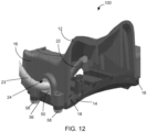
- the cable entry sealing system 100 provides for an electronics enclosure 10, comprising a first enclosure half 12 and a second enclosure half 14.
- the first enclosure half 12 is generally box-shaped and can be formed of any material sufficient to be rigid enough to adequately enclose the electronics housed therein. However, it should be understood that the first enclosure half 12 can be of any shape required to contain the desired electrical components within the enclosure 10.
- the second enclosure half 14 is generally planar, e.g. a cover or lid. However, the second enclosure half 14 can be most any shape capable of effectively mating or combining with the first enclosure half 12 to form a complete enclosure 10.
- the second enclosure half 14 can be formed of material that is the same or different than that of the first enclosure half 12.
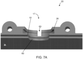
- the first enclosure half 12 comprises at least one sidewall 16 having an aperture 17 located therein (shown in FIG. 6 ).
- the aperture 17 is formed from a cut-out portion of the sidewall 16.
- the aperture 17 allows for electrical conductors confined within a cable to pass through the wall of the enclosure 10.
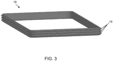
- the enclosure 10 further comprises a sealing member 18 positioned between the first enclosure half 12 and the second enclosure half 14 to provide a seal.
- the sealing member 18 operates in a radial manner so as to seal along the perimeter of the enclosure 10.
- the sealing member 18 can be formed of a single sealing material encompassing the perimeter of the enclosure 10.
- the sealing member 18 is a multi-lip radial seal.
- the sealing member 18 can be an o-ring, quad-ring, or other sealing means of similar elastomeric form.
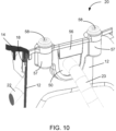
- the cable entry sealing system 100 further comprises a cable entry 20.
- the cable entry 20 is positioned within the aperture 17 located in the sidewall 16.
- the cable entry 20 comprises a cable 22, a cable grommet 24, and a cable grommet support groove 26.
- the cable 22 is further encompassed by a cable jacket 23.
- the cable 22 and the cable jacket 23 extend from the exterior of the enclosure 10, passing through the cable grommet 24 to access the interior of the enclosure 10.
- the cable 22 includes a distal end 22a which terminates within the enclosure 10, and can include connectors or terminals (not shown) for electrically and physically connecting to, for example, a printed circuit board or terminal block within the enclosure 10.
- the cable jacket 23 is fused to the cable grommet 24, where sealing between the cable grommet 24 and the cable 22 is accomplished by fusing the cable grommet 24 with the cable jacket 23 utilizing, for example, a plastic over-mold process.
- a plastic injection molding process can be utilized in which the cable grommet 24 is molded over the cable jacket 23 to provide a seal between the cable grommet 24 and the cable jacket 23.
- the cable grommet 24 is molded over the cable 22 to provide a seal between the cable grommet 24 and the cable 22.
- the seal between the cable grommet 24 and the cable 22 and/or the cable jacket 23 can be impermeable, water-tight, air-tight, and/or water-resistant.
- the cable entry 20 can anchor the cable 22 to the enclosure 10, and provides an integrated strain relief feature which prevents mechanical forces applied at the exterior of the cable from being transferred to electrical terminations at the distal end 22a of the cable 22 within the enclosure 10, and helps to preserve the electrical and mechanical integrity of the cable 22.
- the sealing member 18 is a multi-lip radial seal.
- the multi-lip radial seal is provided in a singular, continuous loop (as shown in FIG. 3 ).
- the sealing member 18 provides sealing or other lip elements 19, wherein such sealing or other lip elements 19 can be in direct contact with the first enclosure half 12, (as best shown in FIG. 8 ).
- the sealing member 18 or multi-lip radial seal allows for multiple contact points along the perimeter of the enclosure 10 thus providing a seal.
- the sealing member 18 can be comprised of any elastic or other compliant material that allows for the transitions included along the perimeter of the enclosure 10 and/or the cable grommet 24, yet still providing compression.
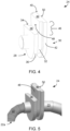
- the cable grommet 24 has a first portion 28 and a second portion 30.
- the first portion 28 and second portion 30 are generally U-shaped, where a recess 32 is formed therebetween.
- the cable grommet 24 can be formed by the molding of a soft or compliant material.
- the cable grommet 24 is formed of thermoplastic elastomer or flexible material. It should be understood by one skilled in the art that the cable grommet 24 can be made of any material sufficiently compliant to adequately form a water-tight seal.
- the cable grommet 24 is generally shaped to fit tightly within the aperture 17.
- the cable grommet 24 is molded as a single piece.
- the cable grommet 24 can be formed of two molded pieces mated together to form a single piece.
- the cable grommet 24 includes a first portion 28 having a first lip 34, where the first lip 34 includes an outer edge 36 and a first lip face 38.
- the cable grommet second portion 30 includes a second lip 40, where the second lip 40 includes an outer edge 42, a second lip face 44, and a projection 46 extending beyond the first lip face 38.
- the projection 46 includes an interior surface 48 and an opposing exterior surface 50.
- the first lip face 38 and the interior surface 48 of the projection 46 converge to form a right angle.
- the cable jacket 23 extends from the second portion 30 through the first portion 28, where the distal end 22a of the cable 22 terminates within the interior of the housing.
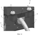
- the cable grommet support groove 26 is shown.
- the cable grommet support groove 26 is located within the sidewall 16 of the first enclosure half 12, and essentially frames the aperture 17. By framing or contouring the aperture 17, the cable grommet support groove 26 positions the flexible cable grommet 24 in the correct and proper location to ensure reliable assembly of the first enclosure half 12 and the second enclosure half 14.
- the cable grommet support groove 26 comprises an optional cutout 63 (as shown in FIGS 7A-7B ), which allows for water drainage on the outside of the cable grommet 24. This optional cutout 63 prevents water from becoming trapped against or within the cable grommet support groove 26, and thus reduces the likelihood of penetration of water into the enclosure 10.
- the cable grommet support groove 26 can be generally U-shaped, and shaped to receive and communicate with the cable grommet 24 to complete the sidewall 16.
- the sidewall 16 further includes an offset face 52 having a ledge 54.
- the offset face 52 correlates with the projection 46 of the cable grommet second portion 30 when the cable grommet 24 is installed. More specifically, and as shown in FIG. 8 , the offset face 52 engages with the interior surface 48 of the projection 46, such that when the cable grommet 24 is installed within the cable grommet support groove 26, the interior surface 48 and the offset face 52 form a contiguous portion of the sidewall 16.
- the offset face 52 is offset inwardly toward the interior of the enclosure so to create the ledge 54 which works to prevent the sealing member 18 from sliding down and falling out of the gland.
- the first lip face 38 of the first portion 28 abuttingly engages with the ledge 54, such that when the cable grommet 24 is installed, the first lip face 38 and the ledge 54 form a contiguous portion.
- the cable entry 20 further comprises a sealing face 60.
- the sealing face 60 is located on the interior side of the enclosure 10. It should be understood that the width of the sealing face 60 can be widened in order to improve sealing capability.
- the aperture 17 is sized so that a compressive force is maintained with the recess 32 (as shown best in FIG. 4 ), which increases the dimensional interference as the cable grommet 24 is pressed within the grommet support groove 26. It should be understood that the aperture 17 can be of any size that complements the size and shape of the cable grommet 24.
- the sealing face 60 further comprises a triangular cross-section or raised knife edge 61.
- the raised knife edge 61 extends over the length of or the perimeter of the sealing face 60.
- this triangular cross-section or knife edge 61 pushes against the cable grommet 24 to provide an increase in localized pressure (or increased compression), which improves sealing.
- the sealing member 18 can be provided (as shown in FIG. 9 ). The sealing member 18 abuttingly engages the offset face 52 and the interior surface 48 of the projection, and is adjacent to the ledge 54 (not shown in FIG. 9 ) and the first lip face 38. When installed, the sealing member 18 remains flush against the housing, sealing itself against the offset face 52 and the interior surface 48 of the projection.
- connection between the recess 32 of the cable grommet 24 and the sealing face 60 provides for a water-tight seal and/or a seal that can prevent environmental contaminants from entering the enclosure 10.
- the sealing member 18 utilizes a plurality of flexible ribs (or sealing elements 61 as shown in FIG. 3 ), which create a high compliant interface that can conform to surface variances that may be present in the offset face 52 and the interior surface 48.
- the unique shape of the cable grommet 24 allows for the gland profile to be completed, and the sealing member 18 can perform as though there was no aperture 17 or cutout within the sidewall 16 of the first enclosure half 12.
- the first enclosure half 12 comprises at least one fastener receptacle 57. As shown in FIG. 9 , two fastener receptacles 57 are shown. Each fastener receptacle 57 receives a fastener 58 to engage the first enclosure half 12 with the second enclosure half 14 to essentially form the complete electronics enclosure 10.
- the fastener can be selected from a screw, bolt, or the like. The fasteners 58 allow for compression against the second lip face 44 to press the cable grommet 24 tightly in the aperture 17, thus ensuring a seal between the recess 32 and the sealing face 60.
- the cable grommet 24 is formed of a compliant material, which is ideal for sealing the enclosure 10.
- the relatively soft material can present challenges when it comes to maintaining the location and flatness of interior surface 48.
- a grommet support 56 is provided to reinforce and maintain the geometry of the grommet 24, and to ensure reliable engagement between the sealing member 18 or multi-lip seal and interior surface 48.
- the grommet support 56 provides additional support to the cable grommet 24 when installed.
- the grommet support 56 is an additional feature provided by, and located on, the second enclosure half 14.
- the grommet support 56 abuttingly engages with the exterior surface 50 of the projection 46 to provide a backing. As such, the grommet support 56 maintains reliable engagement of the cable grommet 24 with the sealing member 18 to effectively supply a waterproof or water-tight electronics enclosure 10.
Landscapes
- Engineering & Computer Science (AREA)
- Architecture (AREA)
- Civil Engineering (AREA)
- Structural Engineering (AREA)
- Microelectronics & Electronic Packaging (AREA)
- Installation Of Indoor Wiring (AREA)
- Insertion, Bundling And Securing Of Wires For Electric Apparatuses (AREA)
Claims (6)
- Kabeleinführungsdichtungsmechanismus, umfassend:ein Gehäuse (10), das eine erste Gehäusehälfte (12) und eine zweite Gehäusehälfte (14) aufweist, wobei die erste Gehäusehälfte mindestens eine Seitenwand (16) umfasst, die eine Öffnung (17) darin aufweist, wobei das Gehäuse einen Innenraum definiert;eine Kabeleinführung (20), die innerhalb der Öffnung (17) positioniert ist, wobei die Kabeleinführung eine Kabeldurchführungsstütznut (26) umfasst, die innerhalb der Seitenwand der ersten Gehäusehälfte gebildet ist und die Öffnung umrahmt; undeine Kabeldurchführung (24), wobei die Kabeldurchführung im Allgemeinen U-förmig ist, einen ersten Abschnitt (28) und einen zweiten Abschnitt (30) umfasst; wobei der erste Abschnitt eine erste Lippe (34) umfasst, wobei die erste Lippe eine erste Außenkante (36) und eine erste Lippenfläche (38) aufweist, und wobei der zweite Abschnitt eine zweite Lippe (40) umfasst, wobei die zweite Lippe eine zweite Außenkante (42), eine zweite Lippenfläche (44) und einen über die erste Lippenfläche hinausragenden Vorsprung (46) aufweist, wobei zwischen dem ersten Abschnitt und dem zweiten Abschnitt eine Vertiefung (32) gebildet ist;wobei die Kabeldurchführungsstütznut (26) dazu geformt ist, die Kabeldurchführung (24) aufzunehmen und mit dieser in Kommunikation zu stehen;wobei die Seitenwand (16) weiter eine versetzte Fläche (52) umfasst, die eine Leiste (54) aufweist;
wobei die versetzte Fläche (52) dazu konfiguriert ist, mit dem Vorsprung (46) derart in Eingriff zu treten, dass, wenn die Kabeldurchführung (24) in der Kabeldurchführungsstütznut (26) installiert ist, der Vorsprung und die versetzte Fläche einen ersten zusammenhängenden Abschnitt der Seitenwand bilden; undwobei der Kabeleinführungsdichtungsmechanismus weiter eine Radialdichtung (18) umfasst, die dazu konfiguriert ist, an dem ersten zusammenhängenden Abschnitt der Seitenwand anliegend einzugreifen, um eine Abdichtung am Umfang des Gehäuses bereitzustellen. - Kabeleinführungsdichtungsmechanismus nach Anspruch 1, wobei die erste Lippenfläche (38) dazu konfiguriert ist, an der Leiste (54) anliegend derart einzugreifen, dass, wenn die Kabeldurchführung (24) in der Kabeldurchführungsstütznut (26) installiert ist, die erste Lippenfläche und die Leiste einen zweiten zusammenhängenden Abschnitt bilden, der neben der Radialdichtung (18) angeordnet ist, wenn die Radialdichtung an dem ersten zusammenhängenden Abschnitt anliegend eingreift.
- Kabeleinführungsdichtungsmechanismus nach Anspruch 1 oder Anspruch 2, wobei die Radialdichtung (18) eine mehrlippige Radialdichtung ist.
- Kabeleinführungsdichtungsmechanismus nach einem der vorstehenden Ansprüche, wobei die Radialdichtung (18) in einer einzigen, durchgehenden Schleife vorgesehen ist.
- Kabeleinführungsdichtungsmechanismus nach einem der vorstehenden Ansprüche, wobei die Kabeleinführung (20) weiter eine Dichtfläche (60) umfasst, wobei die Vertiefung (32) und die Dichtfläche dazu konfiguriert sind, anliegend in Eingriff zu treten, um eine Kabeleinführungsdichtung zu bilden.
- Kabeleinführungsdichtungsmechanismus nach Anspruch 5, wobei die Dichtfläche (60) eine Messerkante (61) umfasst.
Applications Claiming Priority (2)
| Application Number | Priority Date | Filing Date | Title |
|---|---|---|---|
| US201862630338P | 2018-02-14 | 2018-02-14 | |
| PCT/US2019/017760 WO2019160896A1 (en) | 2018-02-14 | 2019-02-13 | Sealing system for electronics enclosure |
Publications (2)
| Publication Number | Publication Date |
|---|---|
| EP3753078A1 EP3753078A1 (de) | 2020-12-23 |
| EP3753078B1 true EP3753078B1 (de) | 2024-12-11 |
Family
ID=65520482
Family Applications (1)
| Application Number | Title | Priority Date | Filing Date |
|---|---|---|---|
| EP19707257.2A Active EP3753078B1 (de) | 2018-02-14 | 2019-02-13 | Dichtungssystem für elektronikgehäuse |
Country Status (5)
| Country | Link |
|---|---|
| US (2) | US11051417B2 (de) |
| EP (1) | EP3753078B1 (de) |
| AU (1) | AU2019222658A1 (de) |
| CA (1) | CA3088967A1 (de) |
| WO (1) | WO2019160896A1 (de) |
Families Citing this family (8)
| Publication number | Priority date | Publication date | Assignee | Title |
|---|---|---|---|---|
| EP3753078B1 (de) * | 2018-02-14 | 2024-12-11 | Mtd Products Inc. | Dichtungssystem für elektronikgehäuse |
| CN109905995A (zh) * | 2019-01-31 | 2019-06-18 | 苏州佳世达光电有限公司 | 防水机构 |
| US11229135B2 (en) * | 2019-04-01 | 2022-01-18 | Dell Products L.P. | Multiple function chassis mid-channel |
| DE102019008320B4 (de) * | 2019-12-01 | 2021-07-15 | Pulsion Medical Systems Se | Vorrichtung zum messen von vitalparametern mit vorteilhafter dichtungsanordnung |
| CN115244775A (zh) * | 2020-03-10 | 2022-10-25 | 株式会社村田制作所 | 电子设备、电池包及电动车辆 |
| CN113891643B (zh) * | 2020-07-03 | 2025-11-14 | 麦格纳电子瑞典公司 | 电子设备 |
| SE544757C2 (en) | 2021-12-06 | 2022-11-01 | Husqvarna Ab | Power tool and grommet |
| US20250385502A1 (en) * | 2024-06-13 | 2025-12-18 | Bentek Corporation | Molded cable seal gland |
Citations (3)
| Publication number | Priority date | Publication date | Assignee | Title |
|---|---|---|---|---|
| EP1860748A1 (de) * | 2006-05-22 | 2007-11-28 | Legrand France | Teilbares elektrisches Gerät zur überstehenden Anordnung oder zum Einbau in eine Wand |
| US20140252722A1 (en) * | 2011-10-06 | 2014-09-11 | Nok Corporation | Seal structure |
| US20160072266A1 (en) * | 2014-09-04 | 2016-03-10 | Leviton Manufacturing Co., Inc. | Weather resistant flip lid cover with improved sealing arrangement |
Family Cites Families (10)
| Publication number | Priority date | Publication date | Assignee | Title |
|---|---|---|---|---|
| JPH06333433A (ja) * | 1993-05-19 | 1994-12-02 | Furukawa Electric Co Ltd:The | グロメット一体型ワイヤーハーネス、その成形型及び成形方法 |
| US5567916A (en) | 1993-06-11 | 1996-10-22 | Siecor Corporation | Grommet |
| JP2001006467A (ja) * | 1999-06-25 | 2001-01-12 | Furukawa Electric Co Ltd:The | ワイヤーハーネス一体型グロメット製造用金型及びこれを用いたワイヤーハーネス一体型グロメットの製造方法 |
| JP3914399B2 (ja) * | 2001-06-12 | 2007-05-16 | 矢崎総業株式会社 | 電気接続箱の防水構造 |
| US6492590B1 (en) * | 2001-07-13 | 2002-12-10 | Ching Chi Cheng | Liquid-proof enclosure of electrical device |
| US7459630B2 (en) | 2006-10-05 | 2008-12-02 | Lear Corporation | Junction box assembly |
| US7445490B2 (en) * | 2007-03-22 | 2008-11-04 | Deere & Company | Integrated overmolded cable seal and gasket for an electronic module |
| FI123060B (fi) * | 2009-02-10 | 2012-10-15 | Fibox Oy Ab | Tiiviste, kotelo tiivisteen vastaanottamiseksi ja menetelmä valokaapelin ohjaamiseksi kotelon sisään |
| KR101545404B1 (ko) * | 2013-12-04 | 2015-08-18 | 엘에스산전 주식회사 | 전기 자동차의 충전기 |
| EP3753078B1 (de) * | 2018-02-14 | 2024-12-11 | Mtd Products Inc. | Dichtungssystem für elektronikgehäuse |
-
2019
- 2019-02-13 EP EP19707257.2A patent/EP3753078B1/de active Active
- 2019-02-13 US US16/274,412 patent/US11051417B2/en active Active
- 2019-02-13 AU AU2019222658A patent/AU2019222658A1/en not_active Abandoned
- 2019-02-13 WO PCT/US2019/017760 patent/WO2019160896A1/en not_active Ceased
- 2019-02-13 CA CA3088967A patent/CA3088967A1/en active Pending
-
2021
- 2021-05-26 US US17/331,066 patent/US11596076B2/en active Active
Patent Citations (3)
| Publication number | Priority date | Publication date | Assignee | Title |
|---|---|---|---|---|
| EP1860748A1 (de) * | 2006-05-22 | 2007-11-28 | Legrand France | Teilbares elektrisches Gerät zur überstehenden Anordnung oder zum Einbau in eine Wand |
| US20140252722A1 (en) * | 2011-10-06 | 2014-09-11 | Nok Corporation | Seal structure |
| US20160072266A1 (en) * | 2014-09-04 | 2016-03-10 | Leviton Manufacturing Co., Inc. | Weather resistant flip lid cover with improved sealing arrangement |
Also Published As
| Publication number | Publication date |
|---|---|
| WO2019160896A1 (en) | 2019-08-22 |
| US11596076B2 (en) | 2023-02-28 |
| US11051417B2 (en) | 2021-06-29 |
| EP3753078A1 (de) | 2020-12-23 |
| AU2019222658A1 (en) | 2020-07-23 |
| US20190254188A1 (en) | 2019-08-15 |
| US20210282287A1 (en) | 2021-09-09 |
| CA3088967A1 (en) | 2019-08-22 |
Similar Documents
| Publication | Publication Date | Title |
|---|---|---|
| US11596076B2 (en) | Sealing system for electronics enclosure | |
| US10368456B2 (en) | Low closure force gasket | |
| US8992245B2 (en) | Connector | |
| US7201609B2 (en) | Connector with a sealing boot having inner and outer sealing lips | |
| US9379477B2 (en) | Seal having a packing portion extending from a flat portion with a step | |
| US9160908B2 (en) | Imaging apparatus | |
| JP6427016B2 (ja) | コネクタ装置 | |
| US9337568B2 (en) | Waterproof connector | |
| CN102187750B (zh) | 带有罐式外壳的电子设备及其制造方法 | |
| EP2961002A1 (de) | Wasserdichter steckverbinder | |
| US10199984B2 (en) | Housing for solar panel electric connection | |
| CN108886207B (zh) | 树脂成形品 | |
| US9627807B2 (en) | Remote radio unit, and cable connector assembly and housing of the same | |
| US20100009570A1 (en) | Method and Apparatus Involving a Housing with a Sealed Electrical Connector | |
| US20060261452A1 (en) | Structural unit and method for the production of a structural unit | |
| US20190028618A1 (en) | Camera module | |
| CN105391231A (zh) | 电动机及用于其的阴型连接器 | |
| CN102185226A (zh) | 基板连接用连接器的防水安装构造 | |
| EP1315271B1 (de) | Motoranschlusskasten | |
| JP2004119294A (ja) | シール材の固定構造 | |
| US20160301361A1 (en) | Housing for Solar Panel Electric Connection | |
| CN111372819A (zh) | 车门模块及车门模块用固定用具 | |
| CN106464206B (zh) | 用于光伏模块的接线盒 | |
| JP2006066208A (ja) | 防水コネクタ | |
| JP5198107B2 (ja) | コネクタ |
Legal Events
| Date | Code | Title | Description |
|---|---|---|---|
| STAA | Information on the status of an ep patent application or granted ep patent |
Free format text: STATUS: UNKNOWN |
|
| STAA | Information on the status of an ep patent application or granted ep patent |
Free format text: STATUS: THE INTERNATIONAL PUBLICATION HAS BEEN MADE |
|
| PUAI | Public reference made under article 153(3) epc to a published international application that has entered the european phase |
Free format text: ORIGINAL CODE: 0009012 |
|
| STAA | Information on the status of an ep patent application or granted ep patent |
Free format text: STATUS: REQUEST FOR EXAMINATION WAS MADE |
|
| 17P | Request for examination filed |
Effective date: 20200806 |
|
| AK | Designated contracting states |
Kind code of ref document: A1 Designated state(s): AL AT BE BG CH CY CZ DE DK EE ES FI FR GB GR HR HU IE IS IT LI LT LU LV MC MK MT NL NO PL PT RO RS SE SI SK SM TR |
|
| AX | Request for extension of the european patent |
Extension state: BA ME |
|
| DAV | Request for validation of the european patent (deleted) | ||
| DAX | Request for extension of the european patent (deleted) | ||
| STAA | Information on the status of an ep patent application or granted ep patent |
Free format text: STATUS: EXAMINATION IS IN PROGRESS |
|
| 17Q | First examination report despatched |
Effective date: 20210908 |
|
| GRAP | Despatch of communication of intention to grant a patent |
Free format text: ORIGINAL CODE: EPIDOSNIGR1 |
|
| STAA | Information on the status of an ep patent application or granted ep patent |
Free format text: STATUS: GRANT OF PATENT IS INTENDED |
|
| INTG | Intention to grant announced |
Effective date: 20240708 |
|
| GRAS | Grant fee paid |
Free format text: ORIGINAL CODE: EPIDOSNIGR3 |
|
| GRAA | (expected) grant |
Free format text: ORIGINAL CODE: 0009210 |
|
| STAA | Information on the status of an ep patent application or granted ep patent |
Free format text: STATUS: THE PATENT HAS BEEN GRANTED |
|
| AK | Designated contracting states |
Kind code of ref document: B1 Designated state(s): AL AT BE BG CH CY CZ DE DK EE ES FI FR GB GR HR HU IE IS IT LI LT LU LV MC MK MT NL NO PL PT RO RS SE SI SK SM TR |
|
| REG | Reference to a national code |
Ref country code: GB Ref legal event code: FG4D |
|
| REG | Reference to a national code |
Ref country code: CH Ref legal event code: EP |
|
| REG | Reference to a national code |
Ref country code: IE Ref legal event code: FG4D |
|
| REG | Reference to a national code |
Ref country code: DE Ref legal event code: R096 Ref document number: 602019063328 Country of ref document: DE |
|
| P01 | Opt-out of the competence of the unified patent court (upc) registered |
Free format text: CASE NUMBER: APP_65950/2024 Effective date: 20241213 |
|
| REG | Reference to a national code |
Ref country code: LT Ref legal event code: MG9D |
|
| PG25 | Lapsed in a contracting state [announced via postgrant information from national office to epo] |
Ref country code: HR Free format text: LAPSE BECAUSE OF FAILURE TO SUBMIT A TRANSLATION OF THE DESCRIPTION OR TO PAY THE FEE WITHIN THE PRESCRIBED TIME-LIMIT Effective date: 20241211 |
|
| PG25 | Lapsed in a contracting state [announced via postgrant information from national office to epo] |
Ref country code: FI Free format text: LAPSE BECAUSE OF FAILURE TO SUBMIT A TRANSLATION OF THE DESCRIPTION OR TO PAY THE FEE WITHIN THE PRESCRIBED TIME-LIMIT Effective date: 20241211 |
|
| PG25 | Lapsed in a contracting state [announced via postgrant information from national office to epo] |
Ref country code: BG Free format text: LAPSE BECAUSE OF FAILURE TO SUBMIT A TRANSLATION OF THE DESCRIPTION OR TO PAY THE FEE WITHIN THE PRESCRIBED TIME-LIMIT Effective date: 20241211 |
|
| REG | Reference to a national code |
Ref country code: NL Ref legal event code: MP Effective date: 20241211 |
|
| PG25 | Lapsed in a contracting state [announced via postgrant information from national office to epo] |
Ref country code: ES Free format text: LAPSE BECAUSE OF FAILURE TO SUBMIT A TRANSLATION OF THE DESCRIPTION OR TO PAY THE FEE WITHIN THE PRESCRIBED TIME-LIMIT Effective date: 20241211 |
|
| PG25 | Lapsed in a contracting state [announced via postgrant information from national office to epo] |
Ref country code: NO Free format text: LAPSE BECAUSE OF FAILURE TO SUBMIT A TRANSLATION OF THE DESCRIPTION OR TO PAY THE FEE WITHIN THE PRESCRIBED TIME-LIMIT Effective date: 20250311 |
|
| PG25 | Lapsed in a contracting state [announced via postgrant information from national office to epo] |
Ref country code: GR Free format text: LAPSE BECAUSE OF FAILURE TO SUBMIT A TRANSLATION OF THE DESCRIPTION OR TO PAY THE FEE WITHIN THE PRESCRIBED TIME-LIMIT Effective date: 20250312 Ref country code: LV Free format text: LAPSE BECAUSE OF FAILURE TO SUBMIT A TRANSLATION OF THE DESCRIPTION OR TO PAY THE FEE WITHIN THE PRESCRIBED TIME-LIMIT Effective date: 20241211 |
|
| PG25 | Lapsed in a contracting state [announced via postgrant information from national office to epo] |
Ref country code: RS Free format text: LAPSE BECAUSE OF FAILURE TO SUBMIT A TRANSLATION OF THE DESCRIPTION OR TO PAY THE FEE WITHIN THE PRESCRIBED TIME-LIMIT Effective date: 20250311 |
|
| PG25 | Lapsed in a contracting state [announced via postgrant information from national office to epo] |
Ref country code: NL Free format text: LAPSE BECAUSE OF FAILURE TO SUBMIT A TRANSLATION OF THE DESCRIPTION OR TO PAY THE FEE WITHIN THE PRESCRIBED TIME-LIMIT Effective date: 20241211 |
|
| REG | Reference to a national code |
Ref country code: AT Ref legal event code: MK05 Ref document number: 1751140 Country of ref document: AT Kind code of ref document: T Effective date: 20241211 |
|
| PG25 | Lapsed in a contracting state [announced via postgrant information from national office to epo] |
Ref country code: SM Free format text: LAPSE BECAUSE OF FAILURE TO SUBMIT A TRANSLATION OF THE DESCRIPTION OR TO PAY THE FEE WITHIN THE PRESCRIBED TIME-LIMIT Effective date: 20241211 |
|
| PG25 | Lapsed in a contracting state [announced via postgrant information from national office to epo] |
Ref country code: PL Free format text: LAPSE BECAUSE OF FAILURE TO SUBMIT A TRANSLATION OF THE DESCRIPTION OR TO PAY THE FEE WITHIN THE PRESCRIBED TIME-LIMIT Effective date: 20241211 |
|
| PGFP | Annual fee paid to national office [announced via postgrant information from national office to epo] |
Ref country code: DE Payment date: 20250519 Year of fee payment: 7 |
|
| PGFP | Annual fee paid to national office [announced via postgrant information from national office to epo] |
Ref country code: GB Payment date: 20250515 Year of fee payment: 7 |
|
| PG25 | Lapsed in a contracting state [announced via postgrant information from national office to epo] |
Ref country code: IS Free format text: LAPSE BECAUSE OF FAILURE TO SUBMIT A TRANSLATION OF THE DESCRIPTION OR TO PAY THE FEE WITHIN THE PRESCRIBED TIME-LIMIT Effective date: 20250411 |
|
| PG25 | Lapsed in a contracting state [announced via postgrant information from national office to epo] |
Ref country code: PT Free format text: LAPSE BECAUSE OF FAILURE TO SUBMIT A TRANSLATION OF THE DESCRIPTION OR TO PAY THE FEE WITHIN THE PRESCRIBED TIME-LIMIT Effective date: 20250411 |
|
| PG25 | Lapsed in a contracting state [announced via postgrant information from national office to epo] |
Ref country code: EE Free format text: LAPSE BECAUSE OF FAILURE TO SUBMIT A TRANSLATION OF THE DESCRIPTION OR TO PAY THE FEE WITHIN THE PRESCRIBED TIME-LIMIT Effective date: 20241211 |
|
| PGFP | Annual fee paid to national office [announced via postgrant information from national office to epo] |
Ref country code: FR Payment date: 20250519 Year of fee payment: 7 |
|
| PG25 | Lapsed in a contracting state [announced via postgrant information from national office to epo] |
Ref country code: AT Free format text: LAPSE BECAUSE OF FAILURE TO SUBMIT A TRANSLATION OF THE DESCRIPTION OR TO PAY THE FEE WITHIN THE PRESCRIBED TIME-LIMIT Effective date: 20241211 Ref country code: RO Free format text: LAPSE BECAUSE OF FAILURE TO SUBMIT A TRANSLATION OF THE DESCRIPTION OR TO PAY THE FEE WITHIN THE PRESCRIBED TIME-LIMIT Effective date: 20241211 |
|
| PG25 | Lapsed in a contracting state [announced via postgrant information from national office to epo] |
Ref country code: SK Free format text: LAPSE BECAUSE OF FAILURE TO SUBMIT A TRANSLATION OF THE DESCRIPTION OR TO PAY THE FEE WITHIN THE PRESCRIBED TIME-LIMIT Effective date: 20241211 |
|
| PG25 | Lapsed in a contracting state [announced via postgrant information from national office to epo] |
Ref country code: CZ Free format text: LAPSE BECAUSE OF FAILURE TO SUBMIT A TRANSLATION OF THE DESCRIPTION OR TO PAY THE FEE WITHIN THE PRESCRIBED TIME-LIMIT Effective date: 20241211 |
|
| PG25 | Lapsed in a contracting state [announced via postgrant information from national office to epo] |
Ref country code: IT Free format text: LAPSE BECAUSE OF FAILURE TO SUBMIT A TRANSLATION OF THE DESCRIPTION OR TO PAY THE FEE WITHIN THE PRESCRIBED TIME-LIMIT Effective date: 20241211 |
|
| PG25 | Lapsed in a contracting state [announced via postgrant information from national office to epo] |
Ref country code: SE Free format text: LAPSE BECAUSE OF FAILURE TO SUBMIT A TRANSLATION OF THE DESCRIPTION OR TO PAY THE FEE WITHIN THE PRESCRIBED TIME-LIMIT Effective date: 20241211 |
|
| REG | Reference to a national code |
Ref country code: DE Ref legal event code: R097 Ref document number: 602019063328 Country of ref document: DE |
|
| PG25 | Lapsed in a contracting state [announced via postgrant information from national office to epo] |
Ref country code: MC Free format text: LAPSE BECAUSE OF FAILURE TO SUBMIT A TRANSLATION OF THE DESCRIPTION OR TO PAY THE FEE WITHIN THE PRESCRIBED TIME-LIMIT Effective date: 20241211 |
|
| REG | Reference to a national code |
Ref country code: CH Ref legal event code: PL |
|
| PG25 | Lapsed in a contracting state [announced via postgrant information from national office to epo] |
Ref country code: DK Free format text: LAPSE BECAUSE OF FAILURE TO SUBMIT A TRANSLATION OF THE DESCRIPTION OR TO PAY THE FEE WITHIN THE PRESCRIBED TIME-LIMIT Effective date: 20241211 |
|
| PG25 | Lapsed in a contracting state [announced via postgrant information from national office to epo] |
Ref country code: LU Free format text: LAPSE BECAUSE OF NON-PAYMENT OF DUE FEES Effective date: 20250213 |
|
| PLBE | No opposition filed within time limit |
Free format text: ORIGINAL CODE: 0009261 |
|
| STAA | Information on the status of an ep patent application or granted ep patent |
Free format text: STATUS: NO OPPOSITION FILED WITHIN TIME LIMIT |
|
| PG25 | Lapsed in a contracting state [announced via postgrant information from national office to epo] |
Ref country code: CH Free format text: LAPSE BECAUSE OF NON-PAYMENT OF DUE FEES Effective date: 20250228 |
|
| 26N | No opposition filed |
Effective date: 20250912 |
|
| REG | Reference to a national code |
Ref country code: BE Ref legal event code: MM Effective date: 20250228 |
|
| PG25 | Lapsed in a contracting state [announced via postgrant information from national office to epo] |
Ref country code: BE Free format text: LAPSE BECAUSE OF NON-PAYMENT OF DUE FEES Effective date: 20250228 |
|
| PG25 | Lapsed in a contracting state [announced via postgrant information from national office to epo] |
Ref country code: IE Free format text: LAPSE BECAUSE OF NON-PAYMENT OF DUE FEES Effective date: 20250213 |