EP3753064B1 - Batterie für ein kraftfahrzeug - Google Patents
Batterie für ein kraftfahrzeug Download PDFInfo
- Publication number
- EP3753064B1 EP3753064B1 EP19703259.2A EP19703259A EP3753064B1 EP 3753064 B1 EP3753064 B1 EP 3753064B1 EP 19703259 A EP19703259 A EP 19703259A EP 3753064 B1 EP3753064 B1 EP 3753064B1
- Authority
- EP
- European Patent Office
- Prior art keywords
- extruded profile
- battery
- cooling
- side surfaces
- battery cell
- Prior art date
- Legal status (The legal status is an assumption and is not a legal conclusion. Google has not performed a legal analysis and makes no representation as to the accuracy of the status listed.)
- Active
Links
Images


Classifications
-
- H—ELECTRICITY
- H01—ELECTRIC ELEMENTS
- H01M—PROCESSES OR MEANS, e.g. BATTERIES, FOR THE DIRECT CONVERSION OF CHEMICAL ENERGY INTO ELECTRICAL ENERGY
- H01M10/00—Secondary cells; Manufacture thereof
- H01M10/60—Heating or cooling; Temperature control
- H01M10/61—Types of temperature control
- H01M10/613—Cooling or keeping cold
-
- H—ELECTRICITY
- H01—ELECTRIC ELEMENTS
- H01M—PROCESSES OR MEANS, e.g. BATTERIES, FOR THE DIRECT CONVERSION OF CHEMICAL ENERGY INTO ELECTRICAL ENERGY
- H01M10/00—Secondary cells; Manufacture thereof
- H01M10/04—Construction or manufacture in general
- H01M10/0481—Compression means other than compression means for stacks of electrodes and separators
-
- H—ELECTRICITY
- H01—ELECTRIC ELEMENTS
- H01M—PROCESSES OR MEANS, e.g. BATTERIES, FOR THE DIRECT CONVERSION OF CHEMICAL ENERGY INTO ELECTRICAL ENERGY
- H01M10/00—Secondary cells; Manufacture thereof
- H01M10/60—Heating or cooling; Temperature control
- H01M10/62—Heating or cooling; Temperature control specially adapted for specific applications
- H01M10/625—Vehicles
-
- H—ELECTRICITY
- H01—ELECTRIC ELEMENTS
- H01M—PROCESSES OR MEANS, e.g. BATTERIES, FOR THE DIRECT CONVERSION OF CHEMICAL ENERGY INTO ELECTRICAL ENERGY
- H01M10/00—Secondary cells; Manufacture thereof
- H01M10/60—Heating or cooling; Temperature control
- H01M10/65—Means for temperature control structurally associated with the cells
- H01M10/655—Solid structures for heat exchange or heat conduction
- H01M10/6551—Surfaces specially adapted for heat dissipation or radiation, e.g. fins or coatings
-
- H—ELECTRICITY
- H01—ELECTRIC ELEMENTS
- H01M—PROCESSES OR MEANS, e.g. BATTERIES, FOR THE DIRECT CONVERSION OF CHEMICAL ENERGY INTO ELECTRICAL ENERGY
- H01M10/00—Secondary cells; Manufacture thereof
- H01M10/60—Heating or cooling; Temperature control
- H01M10/65—Means for temperature control structurally associated with the cells
- H01M10/655—Solid structures for heat exchange or heat conduction
- H01M10/6556—Solid parts with flow channel passages or pipes for heat exchange
-
- H—ELECTRICITY
- H01—ELECTRIC ELEMENTS
- H01M—PROCESSES OR MEANS, e.g. BATTERIES, FOR THE DIRECT CONVERSION OF CHEMICAL ENERGY INTO ELECTRICAL ENERGY
- H01M10/00—Secondary cells; Manufacture thereof
- H01M10/60—Heating or cooling; Temperature control
- H01M10/65—Means for temperature control structurally associated with the cells
- H01M10/656—Means for temperature control structurally associated with the cells characterised by the type of heat-exchange fluid
- H01M10/6567—Liquids
-
- H—ELECTRICITY
- H01—ELECTRIC ELEMENTS
- H01M—PROCESSES OR MEANS, e.g. BATTERIES, FOR THE DIRECT CONVERSION OF CHEMICAL ENERGY INTO ELECTRICAL ENERGY
- H01M10/00—Secondary cells; Manufacture thereof
- H01M10/60—Heating or cooling; Temperature control
- H01M10/64—Heating or cooling; Temperature control characterised by the shape of the cells
- H01M10/647—Prismatic or flat cells, e.g. pouch cells
-
- H—ELECTRICITY
- H01—ELECTRIC ELEMENTS
- H01M—PROCESSES OR MEANS, e.g. BATTERIES, FOR THE DIRECT CONVERSION OF CHEMICAL ENERGY INTO ELECTRICAL ENERGY
- H01M2220/00—Batteries for particular applications
- H01M2220/20—Batteries in motive systems, e.g. vehicle, ship, plane
-
- Y—GENERAL TAGGING OF NEW TECHNOLOGICAL DEVELOPMENTS; GENERAL TAGGING OF CROSS-SECTIONAL TECHNOLOGIES SPANNING OVER SEVERAL SECTIONS OF THE IPC; TECHNICAL SUBJECTS COVERED BY FORMER USPC CROSS-REFERENCE ART COLLECTIONS [XRACs] AND DIGESTS
- Y02—TECHNOLOGIES OR APPLICATIONS FOR MITIGATION OR ADAPTATION AGAINST CLIMATE CHANGE
- Y02E—REDUCTION OF GREENHOUSE GAS [GHG] EMISSIONS, RELATED TO ENERGY GENERATION, TRANSMISSION OR DISTRIBUTION
- Y02E60/00—Enabling technologies; Technologies with a potential or indirect contribution to GHG emissions mitigation
- Y02E60/10—Energy storage using batteries
-
- Y—GENERAL TAGGING OF NEW TECHNOLOGICAL DEVELOPMENTS; GENERAL TAGGING OF CROSS-SECTIONAL TECHNOLOGIES SPANNING OVER SEVERAL SECTIONS OF THE IPC; TECHNICAL SUBJECTS COVERED BY FORMER USPC CROSS-REFERENCE ART COLLECTIONS [XRACs] AND DIGESTS
- Y02—TECHNOLOGIES OR APPLICATIONS FOR MITIGATION OR ADAPTATION AGAINST CLIMATE CHANGE
- Y02P—CLIMATE CHANGE MITIGATION TECHNOLOGIES IN THE PRODUCTION OR PROCESSING OF GOODS
- Y02P70/00—Climate change mitigation technologies in the production process for final industrial or consumer products
- Y02P70/50—Manufacturing or production processes characterised by the final manufactured product
Definitions
- the invention relates to battery technology.
- the invention relates to a battery for a motor vehicle which has an extruded profile as the housing base.
- the invention further relates to a vehicle and a method for producing a battery.
- Battery modules must be protected against the ingress of foreign substances, especially water, and the undefined escape of gases.
- the housings also ensure crash and crush safety and serve to protect the cells. For this reason, it is common practice to create the battery module housing from a tray (housing base) and a lid.
- the tub is usually made of plastic or a metallic material and can be made in one piece or in several parts, with the housing parts having to be sealed to form a closed housing in multi-part variants.
- Metallic housings offer advantages in terms of heat dissipation and the stability of the battery modules, but are often heavier than plastic housings. What all housings have in common is that they should enable passive or active cooling of the battery cells. Furthermore, preloading the battery cells and mechanical protection are often desired functions.
- One-piece housing bases are usually made of plastic, which leads to good degrees of freedom in housing design, but also has low dimensional stability (crash, crush) and lower thermal conductivity compared to metal. Furthermore, “pre-stressing” the battery cells is not easily possible with plastic housings.
- One-piece metal housings are often expensive (die casting, extrusion) or restricted in your creative freedom. Metal housings can also be made in several parts, but these then have to be sealed to form a closed housing. Metal housings are more suitable for biasing the battery cells and can be used as “tie rods”. Cooling elements (passive or active) are usually separate components.
- a system for arranging battery cells is known. It is provided that the battery cells are arranged in a comb-like base support that has a plurality of cooling channels.
- the DE 10 2017 116 219 A1 describes a battery cell arrangement support structure, in which a battery cell support structure has a plurality of spaced-apart support ribs, between which a battery cell is arranged.
- a battery, a vehicle and a method for producing a battery are specified according to the features of the independent claims.
- the exemplary embodiments described relate equally to the battery, the vehicle and the method. In other words, features described below in relation to the battery can also be included in the vehicle and the method, and vice versa.
- a battery for a motor vehicle has a housing base and at least one battery cell.
- the battery can also have several battery cells, which are combined, for example, to form a so-called “stack”.
- the housing base is designed as an extruded profile in the form of a trough, preferably in the form of a U-shaped trough with open end faces.
- the housing base is designed as an extruded profile.
- the extruded profile can preferably be made of aluminum because it is light and dimensionally stable.
- the extruded profile can also contain cooling fins for passive air cooling or cooling channels for active liquid cooling.
- the end faces of the extruded profile are initially open, as in the two exemplary embodiments Figure 1 can be removed.
- this can Extruded profile also serves as a tie rod for pre-stressing prismatic and transversely inserted battery cells.
- the extruded profile according to the invention can also be used for prestressing the battery cells even with pouch cells inserted lengthways (in conjunction with a force flow-closing element on the open top, for example the lid).
- a further advantage of using an extruded profile as the housing base of the battery housing, in particular the trough-shaped or U-shaped housing base in cross section, is given by the possibility of elastically bending the extruded profile. This will also be described further in the method according to the invention.
- the extruded profile is bent up in its elastic area and can be "bent back" after the battery cells have been integrated. Described pictorially, this is done in such a way that the two side walls, as for example in the two exemplary embodiments Figure 1 are shown, be bent laterally so that the battery cells can be integrated between the two side walls.
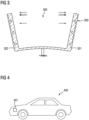
- the bent state of the extruded profile is also in the Figure 3 shown.
- the two initially open end faces of the extruded profile can be tightly closed, for example, by the pressure plates or the end caps. This can be done, for example, by welding the end caps to the end faces of the extruded profile and/or by applying one or more seals. In particular, liquid-tightness and/or gas-tightness of the resulting battery housing can thus be provided.
- such end caps can also contain cooling channels or connections in order to create a closed cooling circuit enable and these can also be customized.
- these end caps can be made of plastic or metal, for example, and their geometric design can be simple or complex.
- an extruded profile in a trough shape or in a U-shape is used as a battery module housing, which is open at the end faces.
- the extruded profile therefore has a first base section, from which two side surfaces extend upwards on opposite sides of the base section or the base surface. This enables the use of both passive and active cooling and can be used modularly. By bending the extruded profile, a positive integration of the battery cells is achieved.
- the concept according to the invention can be used equally for prismatic and pouch battery cells.
- extruded profile is a cost-effective way to create a battery housing, as extruded profiles are available by the meter.
- design measures many of the same components, such as housing covers, pressure plates, etc., processes and assembly methods, can be used for active and passive variants.
- extrusion is a forming process used to produce bars, wires, tubes and irregularly shaped prismatic profiles. According to DIN 8582, extrusion is counted as pressure forming, together with extrusion in the subgroup of pressing, and is described in more detail in DIN 8583.
- the extruded profile is made of metal, preferably aluminum.
- the extruded profile has cooling fins for passive air cooling of the battery and/or has cooling channels for active liquid cooling of the battery.
- the extruded profile has a bottom surface and two lateral side surfaces that extend essentially perpendicularly from the bottom surface. This is schematic in the Figure 1 shown.
- the cooling fins and/or the cooling channels run at least in one of the two side surfaces of the extruded profile.
- cooling fins and/or cooling channels can be realized in extruded profiles without incurring very high costs.
- shaped elements of the profile e.g. geometry of the cooling fins
- crash and crush structures e.g., very application-specific requirements relating to heat dissipation and crash and crush requirements on the battery can be easily met.
- the battery has a first end cap for closing a first End face of the extruded profile and has a second end cap for closing a second end face of the extruded profile.
- the two end caps close the two end faces of the extruded profile in a liquid-tight and/or gas-tight manner by means of one or more weld seams and/or by means of one or more seals. Depending on the application, this can also be achieved using printing plates. In the case of passive systems, end caps can sometimes be dispensed with if the pressure plates can be welded gas- and liquid-tight.
- one or both end caps can have cooling channels, which are arranged relative to the cooling channels in the side walls of the extruded profile in such a way that they together form a closed cooling circuit within the resulting battery housing.
- the battery housing has, in addition to the extruded profile, also the two end caps and a cover as well as pressure plates.
- the two side surfaces of the extruded profile and the at least one battery cell are arranged relative to one another in such a way that the two side surfaces exert a preload force on the battery cell.
- the housing In order to insert the battery cells into the housing base, i.e. into the extruded profile, in a form-fitting manner, the housing is bent up elastically and then bent back after the cells have been integrated (or it "springs back” because it is only bent up elastically). When bent back, the two side surfaces then form one Preload force on the battery cell located in between. (only for pouch cells inserted lengthwise - not the main application, see assembly sequence on page 12).
- the cell stack can be prestressed via pressure plates and the side walls of the extruded profile only ensure a good thermal and mechanical connection through a positive fit. This is the main use case for this concept. If cells are inserted lengthwise (pouch), it is not necessary to work with printing plates. Here the side walls can apply a pre-tension if this is then additionally maintained by another mechanical element (e.g. a firmly attached lid).
- the battery has three heat-conducting elements, each of which is arranged between a side surface and the housing base of the extruded profile and the at least one battery cell.
- these heat-conducting elements can be designed as heat-conducting pads, which are glued to the housing surfaces of the extruded profile and to the housing base on both sides. Heat-conducting elements could also be, for example, a deposited/dispensed thermal paste.
- a vehicle with a battery according to the invention is specified.
- the vehicle is, for example, a motor vehicle, such as a car, a bus or a truck, or also a rail vehicle, a ship, an aircraft, such as a helicopter or airplane.
- an extruded profile as a housing base of a battery housing, in particular in a vehicle battery, is specified.
- a method for producing a battery has the steps of providing a housing base of the battery in the form of a trough-shaped extruded profile, and providing at least one battery cell.
- bending the trough-shaped extruded profile and inserting the at least one battery cell into the bent extruded profile is part of the method.
- Figure 1 shows a first one-piece extruded profile 100 and a second one-piece extruded profile 105, both of which are used as the housing base of a battery housing of a motor vehicle battery. Both extruded profiles essentially have a U-shaped cross section and are therefore referred to as trough-shaped.
- the extruded profile 100 has a first bottom surface 102, to which the first side surface 101 and the second side surface 103 adjoin. Cooling fins 104 for passive air cooling of the battery are arranged on the respective outside of the side surfaces 101 and 103.
- the extruded profile 105 also has a bottom surface 106 and two lateral side walls 107 and 108.
- cooling system is accomplished in that cooling channels 109 are arranged in the two lateral side walls 107 and 108.
- cooling channels 109 are arranged in the two lateral side walls 107 and 108.
- end caps which are applied to the two initially open end faces, there are then adjoining channels in order to provide a closed cooling circuit.
- liquid connections 204 are shown there, which lead into the corresponding cooling channel system.
- the provision of a housing base of the battery in the form of a trough-shaped extruded profile and the provision of at least one battery cell are first method steps. Furthermore, bending the trough-shaped extruded profile and inserting the at least one battery cell into the bent extruded profile is part of the method.
- FIG. 2 shows the two fully assembled batteries resulting from the use of the extruded profiles 100 and 105, as in the Figure 1 shown, revealed.
- the two batteries 200 and 201 therefore differ in the use of different housing bases in the form of different trough-shaped extruded profiles.
- the housing cover of the battery is designated 202 in the right-hand exemplary embodiment with 203.
- the battery has several battery cells. For example, twelve battery cells are provided, with an insulating film being used for cell insulation between two adjacent battery cells. Such an insulating film can, for example, be designed to be adhesive on both sides for cell fixation.
- a so-called cell stack is then formed, in which several battery cells are joined together or on top of each other.
- Two pressure plates are then provided, which are arranged at the top and bottom ends of the battery stack to bias the battery cells.
- a heat-conducting plate can then be positioned on a mounting device, with the pre-stressed battery stack then being glued to the heat-conducting plate, which acts as a floor here.
- the heat-conducting plate can also be a film or paste.
- the housing base is then provided in the form of a U-shaped extruded profile, in particular in the form of a trough.
- Further heat-conducting elements for the side walls and the housing base are arranged on the side surfaces and on the housing base.
- thermal pads can be glued on one side to the side walls and to the housing base of the extruded profile.
- the side surfaces of the housing base can then be bent open in the elastic area of the material, see Figure 3 .
- the battery stack, preloaded with pressure plates, is then inserted into the trough-shaped housing base.
- the side walls of the extruded profile are then bent or springed back, if necessary by pressing them back into the original state of the extruded profile.
- pressure plates are welded to the two end faces of the extruded profile and end caps can be positioned on both sides of the end face in order to be welded all around the housing (or screwed or hot caulked in the case of plastic, etc.). Lateral gaps are welded tightly or sealed with previously inserted or applied seals. In particular, this results in a lateral sealing on the housing, for example by welding, so that overall a liquid-tight and gas-tight battery housing is created. Bus bars, pole connections, contact poles and circuit boards can then be attached to the battery. A vehicle plug with an appropriate seal can then be attached to the battery. A housing cover is then attached together with so-called pole compensation elements. The battery can then be sealed to the housing using a sealant.
- the sealing of the individual elements does not have to be done at the end, but can be done when the corresponding elements are installed by inserting or applying a sealing element (done or by “sealing welding”).
- the previously described manufacturing or assembly method can also be used.
- the end caps can, for example, be made in one piece or in several parts, in particular in three parts. How many parts an end cap has depends very much on the application, and in principle many variants are conceivable.
- a cross section of an extruded profile 300 is shown, which is bent up in the elastic region, and a battery cell or battery cell stack is used therein in the production of a battery according to the invention.
- the two side surfaces 301 and 302 are therefore bent laterally and make it possible to insert one or more battery cells into the interior 303 of the extruded profile.
- the two side walls 301 and 302 are then “bent back” into their original shape.
- FIG. 4 shows a vehicle 400, which is equipped with a battery 401 according to the invention.
- the battery does not necessarily have to be in the engine compartment and could also be integrated in the trunk, for example.
- the vehicle is, for example, a car, but a bus or truck, or even a rail vehicle, a ship, an aircraft, such as a helicopter or airplane, could also be provided with the battery according to the invention.
- an extruded profile in a trough shape or in a U-shape is used as part of the battery housing, with the extruded profile initially being open on the end faces.
- the extruded profile therefore has a first bottom section, of which there are two Side surfaces on opposite sides of the bottom section or the bottom surface extend upwards. This enables the use of both passive and active cooling and can be used modularly.
- a positive integration of the battery cells can be achieved by bending the extruded profile. This concept can be used equally for prismatic and pouch battery cells.
Landscapes
- Engineering & Computer Science (AREA)
- Manufacturing & Machinery (AREA)
- Chemical & Material Sciences (AREA)
- Chemical Kinetics & Catalysis (AREA)
- Electrochemistry (AREA)
- General Chemical & Material Sciences (AREA)
- Secondary Cells (AREA)
- Battery Mounting, Suspending (AREA)
Description
- Die Erfindung betrifft die Batterietechnik. Insbesondere betrifft die Erfindung eine Batterie für ein Kraftfahrzeug welche als Gehäuseboden ein Strangpressprofil aufweist. Darüber hinaus betrifft die Erfindung ein Fahrzeug und ein Verfahren zum Herstellen einer Batterie.
- Batteriemodule sind gegen das Eintreten von Fremdstoffen, insbesondere Wasser und dem undefinierten Austreten von Gasen, zu schützen. Die Gehäuse gewährleisten zudem Crash- und Crushsicherheit und dienen dem Schutz der Zellen. Aus diesem Grund ist es üblich die Batteriemodulgehäuse aus einer Wanne (Gehäuseboden) und einem Deckel zu realisieren. Die Wanne besteht zumeist aus Kunststoff oder einem metallischen Werkstoff und kann einteilig oder mehrteilig ausgeführt sein, wobei bei mehrteiligen Varianten die Gehäuseteile zu einem geschlossenen Gehäuse abgedichtet werden müssen. Metallische Gehäuse bieten dabei Vorteile bei der Entwärmung und der Stabilität der Batteriemodule, sind oft aber auch schwerer als Kunststoffgehäuse. Allen Gehäusen ist gemein, dass Sie eine passive oder aktive Kühlung der Batteriezellen ermöglichen sollen. Weiterhin sind das Vorspannen der Batteriezellen und der mechanische Schutz oft gewünschte Funktionen.
- Einteilig ausgeführte Gehäuseböden sind zumeist aus Kunststoff ausgeführt, was zwar zu guten Freiheitsgraden bei der Gehäusegestaltung führt, aber auch eine geringe Formstabilität (Crash, Crush) sowie geringere thermische Leitfähigkeit gegenüber Metall aufweist. Weiterhin ist das "Vorspannen" der Batteriezellen bei Kunststoffgehäusen nicht ohne weiteres realisierbar. Einteilig ausgeführte Metallgehäuse sind oft teuer (Druckguss, Fließpressen) oder in Ihrer gestalterischen Freiheit eingeschränkt. Metallgehäuse können auch mehrteilig ausgeführt sein, jedoch müssen diese dann zu einem geschlossenen Gehäuse abgedichtet werden. Metallgehäuse eignen sich eher für das Vorspannen der Batteriezellen und können als "Zuganker" eingesetzt werden. Kühlungselemente (passiv oder aktiv) sind meistens separate Bauteile.
- Aus der
US 2016 111 761 A1 ist ein System zur Anordnung von Batteriezellen bekannt. Dabei ist vorgesehen, dass die Batteriezellen in einen kammartigen Grundträger angeordnet werden, der eine Mehrzahl von Kühlkanälen aufweist. - In der
US 2011 059 347 A1 ist eine Batteriemodul mit einer exzellenten Wärmeableitung beschrieben. Zwischen Batteriezellen werden Wärmeableitelement angeordnet, die die Batteriezellen überragen. Auf den Wärmeableitelementen wird eine kammartige Kühlstruktur angeordnet. - Die
DE 10 2017 116 219 A1 beschreibt eine Batteriezellenanordungsträgerstruktur, bei der eine Batteriezellenträgerstruktur eine Mehrzahl von zueinander beabstandeter Tragrippen aufweist, zwischen denen jeweils eine Batteriezelle angeordnet ist. - Aus der
US 2015 255 837 A1 ist ein Energiespeichergehäuse zur Aufnahme von Batteriezellen bekannt, das auf der Außenseite eine Kühlrippenstruktur aufweist. - Es kann als Aufgabe der Erfindung angesehen werden eine alternative, kostengünstige, modulare Batterielösung bereitzustellen, die in einfacher Weise ein Verspannen von Batteriezellen ermöglicht.
- Die Aufgabe der Erfindung wird mittels der Gegenstände der unabhängigen Ansprüche gelöst. Weitere Vorteile und Weiterbildungen sind in den Unteransprüchen angegeben.
- Es sind eine Batterie, ein Fahrzeug, ein Verfahren zum Herstellen einer Batterie gemäß den Merkmalen der unabhängigen Ansprüche angegeben.
- Die beschriebenen Ausführungsbeispiele betreffen gleichermaßen die Batterie, das Fahrzeug sowie das Verfahren. Mit anderen Worten können Merkmale die im Folgenden in Bezug auf die Batterie beschrieben werden, ebenso in dem Fahrzeug sowie dem Verfahren enthalten sein, und umgekehrt.
- Gemäß einem ersten Aspekt der Erfindung ist eine Batterie für ein Kraftfahrzeug angegeben. Die Batterie weist einen Gehäuseboden und mindestens eine Batteriezelle auf. Wie im Folgenden noch detailliert beschrieben wird, kann die Batterie auch mehrere Batteriezellen, die beispielsweise zu einem sogenannten "Stack" zusammengefasst sind, aufweisen. Typischerweise werden mehrere Batteriezellen in der Batterie angeordnet. Weiterhin ist der Gehäuseboden als Strangpressprofil in Form einer Wanne, vorzugsweise in Form einer U-förmigen Wann mit offenen Stirnseiten, ausgeführt.
- Mit anderen Worten wird ein neues Batteriekonzept vorgestellt, bei dem der Gehäuseboden als Strangpressprofil ausgeführt ist. Das Strangpressprofil kann vorzugsweise aus Aluminium ausgeführt sein, da dieses leicht und formstabil ist. Ebenso können in dem Strangpressprofil Kühlrippen zur passiven Luftkühlung oder auch Kühlkanäle zur aktiven Flüssigkeitskühlung enthalten sein. Die Stirnseiten des Strangpressprofils sind dabei zunächst offen, wie diese beispielsweise den beiden Ausführungsbeispielen der
Figur 1 entnommen werden kann. Vorteilhafterweise kann das Strangpressprofil gleichzeitig als Zuganker zum Vorspannen von prismatischen und quer eingelegten Batteriezellen dienen. Jedoch kann das erfindungsgemäße Strangpressprofil auch bei längs eingelegten Pouch-Zellen ebenfalls zum Vorspannen der Batteriezellen verwendet werden (in Verbindung mit einem kraftflussschließendem Element auf der offenen Oberseite, z.B. dem Deckel). - Ein weiterer Vorteil der Verwendung eines Strangpressprofils als Gehäuseboden des Batteriegehäuses, insbesondere des wannenförmigen bzw. des im Querschnitt u-förmigen Gehäusebodens, ist durch die Möglichkeit des elastischen Aufbiegens des Strangpressprofils gegeben. Dies wird auch weiter im erfindungsgemäßen Verfahren beschrieben werden. Um die Batteriezellen formschlüssig in das Gehäuse zu integrieren, wird das Strangpressprofil in seinem elastischen Bereich aufgebogen, und kann nach der Integration der Batteriezellen "zurückgebogen" werden. Bildlich beschrieben erfolgt dies so, dass die beiden Seitenwände, wie sie beispielsweise in den beiden Ausführungsbeispielen der
Figur 1 gezeigt sind, seitlich aufgebogen werden, so dass die Batteriezellen zwischen die beiden Seitenwände integriert werden können. Der aufgebogene Zustand des Strangpressprofils ist auch in derFigur 3 gezeigt. - Die beiden zunächst offenen Stirnseiten des Strangpressprofils können beispielsweise durch die Druckplatten oder die Endkappen dicht verschlossen werden. Dies kann beispielsweise durch Verschweißen der Endkappen an den Stirnseiten des Strangpressprofils und/oder mit dem Aufbringen einer oder mehrerer Dichtungen erfolgen. Insbesondere kann damit eine Flüssigkeitsdichtigkeit und/oder Gasdichtigkeit des dabei entstehenden Gehäuses der Batterie bereitgestellt werden. Solche Endkappen können zusätzlich zur Dichtfunktion auch noch Kühlkanäle oder Anschlüsse enthalten, um einen geschlossenen Kühlkreislauf zu ermöglichen und kundenspezifisch können diese auch angepasst werden. Je nach Anwendungsfall, können diese Endkappen beispielsweise aus Kunststoff oder Metall und in ihrer geometrischen Ausführung einfach oder komplex gestaltet sein.
- Mit anderen Worten wird gemäß der Erfindung ein Strangpressprofil in Wannenform bzw. in U-Form als Batteriemodulgehäuse verwendet, welches an den Stirnseiten offen ist. Das Strangpressprofil weist daher einen ersten Bodenabschnitt auf, von dem sich zwei Seitenflächen an gegenüberliegenden Seiten des Bodenabschnitts bzw. der Bodenfläche nach obenhin erstrecken. Dies ermöglicht sowohl den Einsatz passiver als auch aktiver Kühlung und ist modular einsetzbar. Durch das Aufbiegen des Strangpressprofils wird eine formschlüssige Integration der Batteriezellen erreicht. Das erfindungsgemäße Konzept kann gleichermaßen für prismatische und für Pouch-Batteriezellen eingesetzt werden.
- Die Verwendung eines Strangpressprofils ist eine preisewerte Art zur Realisierung eines Batteriegehäuses, da Strangpressprofile als Meterware vorliegen. Durch gestalterische Maßnahmen können dabei für aktive und passive Varianten viele gleiche Bauteile, zum Beispiel Gehäusedeckel, Druckplatten, etc., Prozesse und Montageverfahren verwendet werden.
- Weiterhin bietet sich damit die Möglichkeit einen Modulbaukasten zu realisieren. Das Strangpressprofil kann dabei in der Länge frei angepasst und anwendungsspezifisch optimiert werden. Weitere Vorteile der vorliegenden Erfindung sind die Einfachheit und der niedrige Preis des Strangpressprofils, die damit bereitgestellte Modularität des Batteriegehäuses, die Möglichkeit des einfachen Vorspannens der Batteriezellen sowie der einfache Toleranzausgleich.
- Der Gehäuseboden des Batteriegehäuses der Batterie der vorliegenden Erfindung wird also mittels Strangpressen hergestellt. Das Strangpressen ist ein Umformverfahren zum Herstellen von Stäben, Drähten, Rohren und unregelmäßig geformten prismatischen Profilen. Das Strangpressen wird nach DIN 8582 zum Druckumformen gezählt, gemeinsam mit dem Fließpressen in der Untergruppe des Durchdrückens, und in DIN 8583 näher beschrieben.
- Erfindungsgemäß ist das Strangpressprofil aus Metall, vorzugsweise aus Aluminium, ausgeführt. Das Strangpressprofil weist Kühlrippen zur passiven Luftkühlung der Batterie auf und/oder weist Kühlkanäle zur aktiven Flüssigkeitskühlung der Batterie auf.
- Erfindungsgemäß weist das Strangpressprofil eine Bodenfläche und zwei sich im Wesentlichen von der Bodenfläche senkrecht erstreckenden seitlichen Seitenflächen auf. Dies ist schematisch in der
Figur 1 gezeigt. - In einem weiter spezifizierten Ausführungsbeispiel verlaufen die Kühlrippen und/oder die Kühlkanäle zumindest in einer der beiden Seitenflächen des Strangpressprofils.
- Vorteilhafterweise können in Strangpressprofilen verschiedenste gewünschte Formen der Kühlrippen und/oder der Kühlkanäle realisiert werden, ohne dass sehr hohe Kosten entstehen. Weiterhin können Formelemente des Profils (z.B. Geometrie der Kühlrippen) gezielt als Crash- und Crushstrukturen eingesetzt werden. Dabei können insbesondere sehr anwendungsspezifische Anforderungen leicht erfüllt werden, die bezüglich der Wärmeableitung und Crash-, Crushanforderungen an der Batterie bestehen.
- Gemäß einem weiteren Ausführungsbeispiel der Erfindung weist die Batterie eine erste Endkappe zum Verschließen einer ersten Stirnseite des Strangpressprofils auf und weist eine zweite Endkappe zum Verschließen einer zweiten Stirnseite des Strangpressprofils auf.
- In einem weiter spezifizierten Ausführungsbeispiel verschließen die beiden Endkappen die beiden Stirnseiten des Strangpressprofils mittels einer oder mehrerer Schweißnähte und/oder mittels einer oder mehrerer Dichtungen flüssigkeitsdicht und/oder gasdicht ab. Dies kann je nach Anwendung auch schon durch Druckplatten realisiert werden. Bei passiven Systemen kann unter Umständen auch auf Endkappen verzichtet werden, sofern die Druckplatten gas- und flüssigkeitsdicht verschweißt werden können.
- Vorteilhafterweise kann in einem Ausführungsbeispiel eine oder beide Endkappen Kühlkanäle aufweisen, welche derart relativ zu den Kühlkanälen in den Seitenwänden des Strangpressprofils angeordnet sind, dass sie gemeinsam einen geschlossenen Kühlkreislauf innerhalb des dabei entstehenden Batteriegehäuses bilden. Das Batteriegehäuse weist in diesem und in anderen bevorzugten Ausführungsbeispielen neben dem Strangpressprofil auch die beiden Endkappen und einen Deckel sowie Druckplatten auf.
- Erfindungsgemäß sind die beiden Seitenflächen des Strangpressprofils und die zumindest eine Batteriezelle derart zu einander angeordnet, dass die beiden Seitenflächen eine Vorspannkraft auf die Batteriezelle ausüben.
- Um die Batteriezellen formschlüssig in den Gehäuseboden, i. e. in das Strangpressprofil, einzubringen, wird das Gehäuse elastisch aufgebogen und nach Integration der Zellen zurückgebogen (bzw. "federt" es zurück da nur elastisch aufgebogen). Im zurückgebogenen Zustand üben dann die beiden Seitenflächen eine Vorspannkraft auf die dazwischen befindliche Batteriezelle auf. (nur bei längs eingelegten pouch-Zellen - nicht Hauptanwendungsfall siehe dazu Montagereihenfolge auf Seite 12).
- Bei quer zur Strangpressrichtung eingelegten Zellen (also prismatischen Zellen) kann der Zellstack über Druckplatten vorgespannt werden und die Seitenwände des Strangpressprofils gewährleisten nur eine gute thermische und mechanische Anbindung durch einen Formschluss. Dies ist für dieses Konzept der Hauptanwendungsfall. Bei längs eingelegten Zellen (pouch) muss nicht mit Druckplatten gearbeitet werden. Hier können die Seitenwände eine Vorspannung aufbringen, wenn diese dann zusätzlich durch ein weiteres mechanisches Element (z.B. ein fest angebundener Deckel) aufrecht erhalten wird.
- Gemäß einem weiteren Ausführungsbeispiel der Erfindung weist die Batterie drei Wärmeleitelemente auf, die jeweils zwischen einer Seitenfläche sowie dem Gehäuseboden des Strangpressprofils und der zumindest einen Batteriezelle angeordnet sind.
- Beispielweise können diese Wärmeleitelemente als Wärmeleitpads ausgeführt sein, die seitlich beidseitig an die Gehäuseflächen des Strangpressprofils und an den Gehäuseboden geklebt werden. Wärmeleitelemente könnte z.B. auch eine abgeschiedene /dispenste Wärmeleitpaste sein.
- Gemäß einem zweiten Aspekt der Erfindung, ist ein Fahrzeug mit einer erfindungsgemäßen Batterie angegeben.
- Bei dem Fahrzeug handelt es sich beispielsweise um ein Kraftfahrzeug, wie ein Auto, ein Bus oder ein Lastkraftwagen, oder aber auch um ein Schienenfahrzeug, ein Schiff, ein Luftfahrzeug, wie Helikopter oder Flugzeug.
- Gemäß einem weiteren Aspekt der Erfindung ist die Verwendung eines Strangpressprofils als Gehäuseboden eines Batteriegehäuses, insbesondere bei einer Fahrzeugbatterie, angegeben.
- Gemäß einem weiteren Aspekt der Erfindung ist ein Verfahren zum Herstellen einer Batterie angegeben. Das Verfahren weist die Schritte des Bereitstellens eines Gehäusebodens der Batterie in Form eines wannenförmigen Strangpressprofils, und das Bereitstellen mindestens einer Batteriezelle auf.
- Weiterhin ist das Aufbiegen des wannenförmigen Strangpressprofils und das Einsetzen der mindestens einen Batteriezelle in das aufgebogene Strangpressprofil Teil des Verfahrens.
- Die Erfindung wird im Folgenden unter Hinweise auf die beigefügten Figuren anhand schematischer Darstellungen bevorzugter Ausführungsbeispiele noch einmal näher erläutert. Hieraus ergeben sich auch weitere Einzelheiten und Vorteile der Erfindung.
-
Figur 1 zeigt zwei Ausführungsbeispiele zwei verschiedener Strangpressprofile, welche jeweils als Gehäuseboden eines Batteriegehäuses verwendet werden. -
Figur 2 zeigt schematische, dreidimensionale Darstellungen der vollständigen Batterien, welche die Strangpressprofile derFigur 1 verwendet. -
Figur 3 zeigt ein aufgebogenes Strangpressprofil zur Integration von einer oder mehreren Batteriezellen in dem Strangpressprofil. -
Figur 4 zeigt ein Fahrzeug mit einer erfindungsgemäßen Fahrzeugbatterie. -
Figur 1 zeigt ein erstes einstückiges Strangpressprofil 100 und ein zweites einstückiges Strangprofil 105, welche beide als Gehäuseboden eines Batteriegehäuses einer Kraftfahrzeugbatterie verwendet werden. Beide Strangpressprofile weisen im Wesentlichen einen U-förmigen Querschnitt auf und sind daher als wannenförmig bezeichnet. Insbesondere weist das Strangpressprofil 100 eine erste Bodenfläche 102 auf, an welche sich die erste Seitenfläche 101 und die zweite Seitenfläche 103 anschließen. Auf der jeweiligen Außenseite der Seitenfläche 101 und 103 sind jeweils Kühlrippen 104 zur passiven Luftkühlung der Batterie angeordnet. Im rechten Ausführungsbeispiel derFigur 1 weist das Strangpressprofil 105 ebenso eine Bodenfläche 106 und zwei seitliche Seitenwände 107 und 108 auf. Jedoch ist in diesem Ausführungsbeispiel das Kühlsystem dadurch bewerkstelligt, dass Kühlkanäle 109 in den beiden seitlichen Seitenwänden 107 und 108 angeordnet sind. In entsprechenden Endkappen, die auf die beiden zunächst offenen Stirnseiten aufgebracht werden, sind dann sich anschließende Kanäle, um einen geschlossenen Kühlreislauf bereitzustellen. Wie derFigur 2 , rechtes Ausführungsbeispiel entnommen werden kann, sind dort Flüssigkeitsanschlüsse 204 gezeigt, welche in das entsprechende Kühlkanalsystem einführen. - Gemäß dem erfindungsgemäßen Verfahren zum Herstellen einer Batterie sind das Bereitstellen eines Gehäusebodens der Batterie in Form eines wannenförmigen Strangpressprofils, und das Bereitstellen mindestens einer Batteriezelle erste Verfahrensschritte. Weiterhin ist das Aufbiegen des wannenförmigen Strangpressprofils und das Einsetzen der mindestens einen Batteriezelle in das aufgebogene Strangpressprofil Teil des Verfahrens.
-
Figur 2 zeigt die zwei vollständig zusammengebauten Batterien, welche sich aus der Verwendung der Strangpressprofile 100 und 105, wie in derFigur 1 gezeigt, ergeben. Die beiden Batterien 200 und 201 unterscheiden sich daher durch die Verwendung unterschiedlicher Gehäuseböden in Form von wannenförmigen unterschiedlichen Strangpressprofilen. Im linken Ausführungsbeispiel derFigur 2 ist der Gehäusedeckel der Batterie mit 202 im rechten Ausführungsbeispiel mit 203 bezeichnet. - Im Folgenden werden weitere Aspekte des Zusammenfügens der weiteren Komponenten der Batterie zwischen dem Stadium, gezeigt in
Figur 1 , und der finalen Batterie, gezeigt inFigur 2 , beschrieben werden. - Zunächst wird im Folgenden ein detailliertes Ausführungsbeispiel angegeben, bei dem eine erfindungsgemäße Batterie mit passiver Kühlung zusammengesetzt wird. In diesem Ausführungsbeispiel weist die Batterie mehrere Batteriezellen auf. Beispielsweise werden zwölf Batteriezellen bereitgestellt, wobei zwischen zwei benachbarten Batteriezellen jeweils eine Isolierfolie zur Zellisolierung verwendet wird. Eine solche Isolierfolie kann beispielweise beidseitig klebend zur Zellfixierung ausgeführt sein. Daraufhin wird ein sogenannter Zell-Stack gebildet, in dem mehrere Batteriezellen aneinander- oder aufeinandergefügt werden. Anschließend werden zwei Druckplatten bereitgestellt, welche zum Vorspannen der Batteriezellen am oberen und unteren Ende des Batterie-Stacks angeordnet werden. Anschließend kann eine Wärmeleitplatte auf einer Montagevorrichtung positioniert werden, wobei anschließend der vorgespannte Batterie-Stack auf die Wärmeleitplatte, der hier als Boden fungiert, geklebt wird. Die Wärmeleitplatte kann auch eine Folie oder Paste sein.
- Die Montagereihenfolge am Beispiel quer eingelegter prismatischer Zellen kann wie folgt sein:
- Die gegeneinander elektrisch isolierten Batteriezellen werden gestackt.
- Der Stack wird mit zwei Druckplatten vorgespannt. Die Druckplatten liegen dann jeweils an die Stirnflächen der beiden äußeren Zellen an, also bezogen auf das Strangpressprofil längsseitig.
- Die Vorspannung wird aufrechterhalten. Vorbaugruppe Stack mit Druckplatten.
- Der Gehäuseboden wird mit Wärmeleitpads bzw. -paste am Gehäuseboden und den Seitenflächen ausgestattet und aufgebogen.
- Der vorgespannte Zellstack wird mit Druckplatten in das Strangpressprofil eingesetzt.
- Die Druckplatten werden im immer noch vorgespannten Zustand mit der Gehäusewanne verschweißt (vorzugsweise gas- und flüssigkeitsdicht). Bei passiv gekühlter Variante könnten die Druckplatten bei Dichtigkeit auch als Endkappen dienen.
- Die Druckplatten können dabei auf den Stirnflächen des Strangpressprofils aufliegen (Zellen sind auf Weg verspannt) oder in das Strangpressprofil formschlüssig einsinken (Zellen sind auf Kraft verspannt und ein leichter Toleranzausgleich in Längsrichtung ist gewährleistet).
- Nach dem Schweißen wird die Vorspannkraft dann durch das Strangpressprofil aufrecht erhalten, da dieses nun als Zuganker dient (wäre bei längs eingelegten Zellen nicht der Fall).
- An den Stirnflächen "über" den Druckplatten können jetzt Endkappen zum Abdichten (über Dichtung, Dichtpasten, etc.) oder zur Ausbildung eines Kühlkanals oder weiterer Erfordernisse (Steckerbereitstellung, Gasauslass, etc.) angeordnet werden.
- Anschließend wird das Gehäuse mittels einer Dichtung/-paste mit einem Deckel gas-und flüssigkeitsdicht (je nach IP Klasse) verschlossen.
- Anschließend wird der Gehäuseboden in Form eines u-förmigen Strangpressprofils, insbesondere in Form einer Wanne, bereitgestellt. Weitere Wärmeleitelemente für die Seitenwände und des Gehäusebodens werden an den Seitenflächen und am Gehäuseboden angeordnet. Beispielsweise können Wärmeleitpads einseitig klebend an den Seitenwänden und am Gehäuseboden des Strangpressprofils verklebt werden. Anschließend können die Seitenflächen des Gehäusebodens aufgebogen werden und zwar im elastischen Bereich des Materials, siehe
Figur 3 . Anschließend erfolgt das Einsetzten des mit Druckplatten vorgespannten Batterie-Stacks in den wannenförmigen Gehäuseboden. Anschließend erfolgt ein Zurückbiegen bzw. -federn der Seitenwände des Strangpressprofils ggf. durch Nachdrücken in den Ursprungszustand des Strangpressprofils. Zusätzlich werden Druckplatten an den beiden Stirnseiten des Strangpressprofils angeschweißt und beidseitig können an der Stirnseite Endkappen positioniert werden um mit dem Gehäuse umlaufend verschweißt zu werden (oder verschraubt oder bei Kunststoff heiß verstemmt, etc.). Seitliche Spalte werden dabei dicht geschweißt oder mit zuvor eingelegten oder aufgebrachten Dichtungen abgedichtet. Insbesondere erfolgt dadurch am Gehäuse per z.B. Schweißen ein seitliches Abdichten, so dass insgesamt ein flüssigkeitsdichtes und gasdichtes Batteriegehäuse entsteht. Anschließend kann das Anbringen von Bus-Bars, Polanschlüssen Kontaktpolen und Leiterplatten auf der Batterie erfolgen. Ebenso kann anschließend an der Batterie ein Fahrzeugstecker mit entsprechender Dichtung angebracht werden. Anschließend erfolgt das Aufbringen eines Gehäusedeckels zusammen mit sogenannten Polausgleichselementen. Mittels einer Dichtmasse kann die Batterie anschließend am Gehäuse abgedichtet werden. - Das Abdichten der einzelnen Elemente muss nicht zum Schluss erfolgen, sondern kann bei Montage der entsprechenden Elemente durch Einlegen oder Aufbringen eines Dichtelements (erfolgen oder aber durch "Dichtschweißen").
- In einem anderen Ausführungsbeispiel, welches aktive Kühlung mit den zuvor beschriebenen Kühlkanälen in den Seitenwänden des Strangpressprofils benutzt, kann das zuvor beschriebene Herstellungs- bzw. Montageverfahren ebenso verwendet werden. Jedoch können hier die Endkappen beispielweise einteilig oder mehrteilig, insbesondere dreiteilig ausgeführt sein. Wie viele Teile eine Endkappe aufweist kommt sehr stark auf den Anwendungsfall an, und grundsätzlich sind viele Varianten denkbar.
- In der
Figur 3 , ist ein Querschnitt eines Strangpressprofils 300 gezeigt, welches im elastischen Bereich aufgebogen wird, und darin eine Batteriezelle oder Batteriezellstack bei der Herstellung einer erfindungsgemäßen Batterie eingesetzt wird. Die beiden Seitenflächen 301 und 302 sind daher seitlich aufgebogen und ermöglichen es in das Innere 303 des Strangpressprofils die eine oder mehrere Batteriezellen einzusetzen. Anschließend werden die beiden Seitenwände 301 und 302 wieder in ihre ursprüngliche Form "zurückgebogen". -
Figur 4 zeigt ein Fahrzeug 400, welches mit einer erfindungsgemäßen Batterie 401 ausgestattet ist. Die Batterie muss nicht zwingend im Motorraum liegen und könnte z.B. auch in den Kofferraum integriert sein. Bei dem Fahrzeug handelt es sich beispielsweise um ein Auto, es könnte aber ebenso ein Bus oder Lastkraftwagen, oder aber auch ein Schienenfahrzeug, ein Schiff, ein Luftfahrzeug, wie Helikopter oder Flugzeug mit der erfindungsgemäßen Batterie versehen sein. Mit anderen Worten wird damit ein Strangpressprofil in Wannenform bzw. in U-Form als Teil des Batteriegehäuses verwendet, wobei das Strangpressprofil an den Stirnseiten zunächst offen ist. Das Strangpressprofil weist daher einen ersten Bodenabschnitt auf, von dem sich zwei Seitenflächen an gegenüberliegenden Seiten des Bodenabschnitts bzw. der Bodenfläche nach obenhin erstrecken. Dies ermöglicht sowohl den Einsatz passiver als auch aktiver Kühlung und ist modular einsetzbar. Vorteilhafterweise kann durch Aufbiegen des Strangpressprofils eine formschlüssige Integration der Batteriezellen erreicht werden. Dieses Konzept kann gleichermaßen für prismatische und für Pouch-Batteriezellen eingesetzt werden.
Claims (9)
- Batterie für ein Kraftfahrzeug, die Batterie aufweisend einen Gehäuseboden,mindestens eine Batteriezelle, undwobei der Gehäuseboden als Strangpressprofil in Form einer Wanne ausgeführt ist, wobeidas Strangpressprofil eine Bodenfläche und zwei sich im Wesentlichen von der Bodenfläche senkrecht erstreckenden seitlichen Seitenflächen aufweist, unddas Strangpressprofil an beiden Stirnseiten offen ist, wobei das Strangpressprofil aus Metall ausgebildet ist, unddie beiden Seitenflächen und die zumindest eine Batteriezelle derart zueinander angeordnet sind, dass die beiden Seitenflächen eine Vorspannkraft auf die Batteriezelle ausüben.
- Batterie gemäß Anspruch 1,wobei das Strangpressprofil aus Aluminium, ausgeführt ist,wobei das Strangpressprofil Kühlrippen zur passiven Luftkühlung der Batterie aufweist, und/oderwobei das Strangpressprofil Kühlkanäle zur aktiven Flüssigkeitskühlung der Batterie aufweist.
- Batterie nach Anspruch 2
wobei die Kühlrippen und/oder Kühlkanäle zumindest in einer der beiden Seitenflächen des Strangpressprofils verlaufen. - Batterie gemäß einem der vorherigen Ansprüche, weiterhin aufweisendeine erste Endkappe zum Verschließen einer ersten Stirnseite des Strangpressprofils, undeine zweite Endkappe zum Verschließen einer zweiten Stirnseite des Strangpressprofils.
- Batterie gemäß Anspruch 4,
wobei die beiden Endkappen die beiden Stirnseiten des Strangpressprofils mittels einer oder mehreren Schweißnähten und/oder einer Dichtung flüssigkeitsdicht und/oder gasdicht verschließen. - Batterie gemäß Anspruch 4 oder 5,
wobei zumindest eine Endkappe Kühlkanäle aufweist, welche derart angeordnet sind, dass zusammen mit Kühlkanälen des Strangpressprofils ein geschlossener Kühlkreislauf bereitgestellt wird. - Batterie gemäß einem der vorhergehenden Ansprüche, weiterhin aufweisend
drei Wärmeleitelemente, die jeweils zwischen einer Seitenfläche und dem Boden des Strangpressprofils und der zumindest einen Batteriezelle angeordnet sind. - Fahrzeug mit einer Batterie gemäß einem der vorhergehenden Ansprüche.
- Verfahren zum Herstellen einer Batterie, das Verfahren aufweisend die Schritte:Bereitstellen eines Gehäusebodens der Batterie in Form eines wannenförmigen Strangpressprofils, wobei das Strangpressprofil eine Bodenfläche und zwei sich im Wesentlichen von der Bodenfläche senkrecht erstreckenden seitlichen Seitenflächen aufweist, das Strangpressprofil an beiden Stirnseiten offen ist, und das Strangpressprofil aus Metall ausgebildet ist;Bereitstellen mindestens einer Batteriezelle, und Aufbiegen des wannenförmigen Strangpressprofils, insbesondere im elastischen Bereich, und Einsetzen der mindestens einen Batteriezelle in das aufgebogene Strangpressprofil, wobei die beiden Seitenflächen und die zumindest eine Batteriezelle derart zueinander angeordnet sind, so dass über die beiden Seitenflächen eine Vorspannkraft auf die Batteriezelle ausgeübt wird.
Applications Claiming Priority (2)
| Application Number | Priority Date | Filing Date | Title |
|---|---|---|---|
| DE102018202263.1A DE102018202263A1 (de) | 2018-02-14 | 2018-02-14 | Batterie für ein Kraftfahrzeug |
| PCT/EP2019/051940 WO2019158346A1 (de) | 2018-02-14 | 2019-01-28 | Batterie für ein kraftfahrzeug |
Publications (2)
| Publication Number | Publication Date |
|---|---|
| EP3753064A1 EP3753064A1 (de) | 2020-12-23 |
| EP3753064B1 true EP3753064B1 (de) | 2024-03-13 |
Family
ID=65279523
Family Applications (1)
| Application Number | Title | Priority Date | Filing Date |
|---|---|---|---|
| EP19703259.2A Active EP3753064B1 (de) | 2018-02-14 | 2019-01-28 | Batterie für ein kraftfahrzeug |
Country Status (4)
| Country | Link |
|---|---|
| EP (1) | EP3753064B1 (de) |
| CN (1) | CN111684640A (de) |
| DE (1) | DE102018202263A1 (de) |
| WO (1) | WO2019158346A1 (de) |
Families Citing this family (5)
| Publication number | Priority date | Publication date | Assignee | Title |
|---|---|---|---|---|
| DE102019126061A1 (de) * | 2019-09-27 | 2021-04-01 | Bayerische Motoren Werke Aktiengesellschaft | Batteriemodul |
| DE102020103793A1 (de) | 2020-02-13 | 2021-08-19 | Hbpo Gmbh | Gehäuse zur Aufnahme eines Batteriemoduls |
| DE102020112656A1 (de) | 2020-05-11 | 2021-11-11 | Dr. Ing. H.C. F. Porsche Aktiengesellschaft | Traktionsbatterie eines Kraftfahrzeugs |
| CN116998053A (zh) * | 2022-01-11 | 2023-11-03 | 宁德时代新能源科技股份有限公司 | 电池壳体结构及其制造方法、电池及用电设备 |
| DE102023120483A1 (de) | 2023-08-02 | 2025-02-06 | Dr. Ing. H.C. F. Porsche Aktiengesellschaft | Flüssigkeitsgekühlte Hochvolt-Traktionsbatterie |
Family Cites Families (16)
| Publication number | Priority date | Publication date | Assignee | Title |
|---|---|---|---|---|
| EP2416439B1 (de) * | 2009-04-01 | 2015-07-29 | LG Chem, Ltd. | Batteriemodul aufweisend eine hervorragende wärmeabstrahlungfähigkeit und batteriepack damit |
| US8383260B2 (en) * | 2010-02-26 | 2013-02-26 | GM Global Technology Operations LLC | U-formed cooling plate with solid fins for lithium pouch cells |
| BR112012031165A2 (pt) * | 2010-06-09 | 2016-11-01 | Nissan Motor | módulo de bateria |
| GB2483079B (en) * | 2010-08-25 | 2012-12-19 | Lightning Car Company Ltd | Battery module |
| WO2012133709A1 (ja) * | 2011-03-31 | 2012-10-04 | 三洋電機株式会社 | 電源装置及び電源装置を備える車両 |
| DE102012208239A1 (de) * | 2012-05-16 | 2013-11-21 | Robert Bosch Gmbh | Batteriebaugruppe |
| WO2014184419A1 (en) * | 2013-05-15 | 2014-11-20 | Valmet Automotive Oy | System for packaging and thermal management of battery cells |
| US20160126514A1 (en) * | 2013-06-19 | 2016-05-05 | Hitachi Automotive Systems, Ltd. | Battery module |
| DE102013113352A1 (de) * | 2013-12-03 | 2015-06-03 | Dr. Ing. H.C. F. Porsche Aktiengesellschaft | Starterbatterie eines Kraftfahrzeugs |
| EP2916366B1 (de) * | 2014-03-05 | 2018-01-31 | Volvo Car Corporation | Energiespeicherungsgehäuse |
| US10622687B2 (en) * | 2015-08-10 | 2020-04-14 | Ford Global Technologies, Llc | Battery pack enclosure including integrated fluid channel |
| US10038173B2 (en) * | 2016-01-05 | 2018-07-31 | GM Global Technology Operations LLC | Extruded battery enclosure joint configuration |
| DE102016109931B4 (de) * | 2016-05-30 | 2024-11-07 | Lisa Dräxlmaier GmbH | Kühlvorrichtung und Verfahren |
| DE102016212783A1 (de) * | 2016-07-13 | 2018-01-18 | Bayerische Motoren Werke Aktiengesellschaft | Batterie |
| US10374271B2 (en) * | 2016-07-21 | 2019-08-06 | Ford Global Technologies, Llc | Battery cell assembly support structure |
| DE102016213832B4 (de) * | 2016-07-27 | 2018-07-26 | Volkswagen Aktiengesellschaft | Unterschale für ein Batteriegehäuse mit integrierter Kühlung und Traktionsbatterie für ein Kraftfahrzeug |
-
2018
- 2018-02-14 DE DE102018202263.1A patent/DE102018202263A1/de not_active Withdrawn
-
2019
- 2019-01-28 WO PCT/EP2019/051940 patent/WO2019158346A1/de not_active Ceased
- 2019-01-28 CN CN201980013646.4A patent/CN111684640A/zh active Pending
- 2019-01-28 EP EP19703259.2A patent/EP3753064B1/de active Active
Also Published As
| Publication number | Publication date |
|---|---|
| WO2019158346A1 (de) | 2019-08-22 |
| EP3753064A1 (de) | 2020-12-23 |
| DE102018202263A1 (de) | 2019-08-14 |
| CN111684640A (zh) | 2020-09-18 |
Similar Documents
| Publication | Publication Date | Title |
|---|---|---|
| EP3753064B1 (de) | Batterie für ein kraftfahrzeug | |
| EP2497145B1 (de) | Energiespeichervorrichtung | |
| EP2797137B1 (de) | Batteriesystem | |
| WO2020259879A1 (de) | Energiespeichereinrichtung für ein kraftfahrzeug, kraftfahrzeug sowie herstellungsverfahren | |
| EP2715833B1 (de) | Energiespeichermodul aus mehreren prismatischen speicherzellen | |
| DE102015225350A1 (de) | Gehäuse zur Aufnahme eines Brennstoffzellen-, Batterie- oder Kondensatorstapels | |
| DE102006059989A1 (de) | Anordnung zur Kühlung einer aus mehreren Einzelzellen bestehenden Batterie sowie Verfahren zur Herstellung der Anordnung | |
| DE102008034873A1 (de) | Batterie, insbesondere Fahrzeugbatterie | |
| DE102016208053B4 (de) | Fahrzeug mit einem Hochvoltspeicher | |
| DE102009030016A1 (de) | Vorrichtung zur Spannungsversorung eines Kraftfahrzeugs mit einem Kühlerblock | |
| DE102019201986A1 (de) | Batteriegehäuse zur Aufnahme wenigstens eines Zellmoduls einer Traktionsbatterie | |
| DE102018203108B4 (de) | Zellmodul mit mehrteiligem Gehäuse | |
| WO2013000882A1 (de) | Elektrische batterie | |
| DE102015118747A1 (de) | Kühlmodul für eine Batterie, Batterie für ein Fahrzeug und Verfahren zur Herstellung eines Kühlmoduls | |
| DE102015011281B4 (de) | Zellblock für eine elektrische Batterie | |
| EP4070407B1 (de) | Modulschicht und daraus aufgebautes batteriesystem | |
| DE102017104709A1 (de) | Batteriemodul zur Verwendung bei einem Hochvolt-Energiespeicher | |
| EP3959755B1 (de) | Energiespeichervorrichtung und fahrzeug | |
| DE102019120606B4 (de) | Gehäuse für eine Batteriezellen-Anordnung, Verfahren zu dessen Herstellung und temperierte Batteriezellen-Anordnung | |
| WO2023057325A1 (de) | Kraftfahrzeug und batterie mit kühlelement | |
| EP4120432A2 (de) | Energiespeichervorrichtung mit einem batterie-zellenmodul und einer folienkühleinrichtung, vorzugsweise für ein zumindest teilweise elektrisch angetriebenes fahrzeug, und verfahren zur herstellung der energiespeichervorrichtung | |
| EP4345997A1 (de) | Stromschienenanordnung, fahrzeugbatterie und herstellverfahren einer stromschienenanordnung | |
| DE102009050960B4 (de) | Energiespeicher und Verfahren zum Kühlen eines solchen Energiespeichers | |
| EP4178016A2 (de) | Batteriegehäusemodulanordnung zur aufnahme zumindest einer batterieeinheit, insbesondere einer batterieeinheit einer traktionsbatterie, eines elektromotorisch antreibbaren fahrzeugs | |
| DE102021202709A1 (de) | Batteriemodul und Verfahren zur Herstellung eines Batteriemoduls |
Legal Events
| Date | Code | Title | Description |
|---|---|---|---|
| STAA | Information on the status of an ep patent application or granted ep patent |
Free format text: STATUS: UNKNOWN |
|
| STAA | Information on the status of an ep patent application or granted ep patent |
Free format text: STATUS: THE INTERNATIONAL PUBLICATION HAS BEEN MADE |
|
| PUAI | Public reference made under article 153(3) epc to a published international application that has entered the european phase |
Free format text: ORIGINAL CODE: 0009012 |
|
| STAA | Information on the status of an ep patent application or granted ep patent |
Free format text: STATUS: REQUEST FOR EXAMINATION WAS MADE |
|
| 17P | Request for examination filed |
Effective date: 20200914 |
|
| AK | Designated contracting states |
Kind code of ref document: A1 Designated state(s): AL AT BE BG CH CY CZ DE DK EE ES FI FR GB GR HR HU IE IS IT LI LT LU LV MC MK MT NL NO PL PT RO RS SE SI SK SM TR |
|
| AX | Request for extension of the european patent |
Extension state: BA ME |
|
| DAV | Request for validation of the european patent (deleted) | ||
| DAX | Request for extension of the european patent (deleted) | ||
| RAP3 | Party data changed (applicant data changed or rights of an application transferred) |
Owner name: VITESCO TECHNOLOGIES GERMANY GMBH |
|
| P01 | Opt-out of the competence of the unified patent court (upc) registered |
Effective date: 20230530 |
|
| GRAP | Despatch of communication of intention to grant a patent |
Free format text: ORIGINAL CODE: EPIDOSNIGR1 |
|
| STAA | Information on the status of an ep patent application or granted ep patent |
Free format text: STATUS: GRANT OF PATENT IS INTENDED |
|
| INTG | Intention to grant announced |
Effective date: 20231027 |
|
| GRAS | Grant fee paid |
Free format text: ORIGINAL CODE: EPIDOSNIGR3 |
|
| GRAA | (expected) grant |
Free format text: ORIGINAL CODE: 0009210 |
|
| STAA | Information on the status of an ep patent application or granted ep patent |
Free format text: STATUS: THE PATENT HAS BEEN GRANTED |
|
| AK | Designated contracting states |
Kind code of ref document: B1 Designated state(s): AL AT BE BG CH CY CZ DE DK EE ES FI FR GB GR HR HU IE IS IT LI LT LU LV MC MK MT NL NO PL PT RO RS SE SI SK SM TR |
|
| REG | Reference to a national code |
Ref country code: GB Ref legal event code: FG4D Free format text: NOT ENGLISH |
|
| REG | Reference to a national code |
Ref country code: CH Ref legal event code: EP |
|
| REG | Reference to a national code |
Ref country code: DE Ref legal event code: R096 Ref document number: 502019010788 Country of ref document: DE |
|
| REG | Reference to a national code |
Ref country code: IE Ref legal event code: FG4D Free format text: LANGUAGE OF EP DOCUMENT: GERMAN |
|
| PG25 | Lapsed in a contracting state [announced via postgrant information from national office to epo] |
Ref country code: LT Free format text: LAPSE BECAUSE OF FAILURE TO SUBMIT A TRANSLATION OF THE DESCRIPTION OR TO PAY THE FEE WITHIN THE PRESCRIBED TIME-LIMIT Effective date: 20240313 |
|
| REG | Reference to a national code |
Ref country code: LT Ref legal event code: MG9D |
|
| PG25 | Lapsed in a contracting state [announced via postgrant information from national office to epo] |
Ref country code: GR Free format text: LAPSE BECAUSE OF FAILURE TO SUBMIT A TRANSLATION OF THE DESCRIPTION OR TO PAY THE FEE WITHIN THE PRESCRIBED TIME-LIMIT Effective date: 20240614 |
|
| REG | Reference to a national code |
Ref country code: NL Ref legal event code: MP Effective date: 20240313 |
|
| PG25 | Lapsed in a contracting state [announced via postgrant information from national office to epo] |
Ref country code: HR Free format text: LAPSE BECAUSE OF FAILURE TO SUBMIT A TRANSLATION OF THE DESCRIPTION OR TO PAY THE FEE WITHIN THE PRESCRIBED TIME-LIMIT Effective date: 20240313 Ref country code: RS Free format text: LAPSE BECAUSE OF FAILURE TO SUBMIT A TRANSLATION OF THE DESCRIPTION OR TO PAY THE FEE WITHIN THE PRESCRIBED TIME-LIMIT Effective date: 20240613 |
|
| PG25 | Lapsed in a contracting state [announced via postgrant information from national office to epo] |
Ref country code: ES Free format text: LAPSE BECAUSE OF FAILURE TO SUBMIT A TRANSLATION OF THE DESCRIPTION OR TO PAY THE FEE WITHIN THE PRESCRIBED TIME-LIMIT Effective date: 20240313 |
|
| PG25 | Lapsed in a contracting state [announced via postgrant information from national office to epo] |
Ref country code: RS Free format text: LAPSE BECAUSE OF FAILURE TO SUBMIT A TRANSLATION OF THE DESCRIPTION OR TO PAY THE FEE WITHIN THE PRESCRIBED TIME-LIMIT Effective date: 20240613 Ref country code: NO Free format text: LAPSE BECAUSE OF FAILURE TO SUBMIT A TRANSLATION OF THE DESCRIPTION OR TO PAY THE FEE WITHIN THE PRESCRIBED TIME-LIMIT Effective date: 20240613 Ref country code: LT Free format text: LAPSE BECAUSE OF FAILURE TO SUBMIT A TRANSLATION OF THE DESCRIPTION OR TO PAY THE FEE WITHIN THE PRESCRIBED TIME-LIMIT Effective date: 20240313 Ref country code: HR Free format text: LAPSE BECAUSE OF FAILURE TO SUBMIT A TRANSLATION OF THE DESCRIPTION OR TO PAY THE FEE WITHIN THE PRESCRIBED TIME-LIMIT Effective date: 20240313 Ref country code: GR Free format text: LAPSE BECAUSE OF FAILURE TO SUBMIT A TRANSLATION OF THE DESCRIPTION OR TO PAY THE FEE WITHIN THE PRESCRIBED TIME-LIMIT Effective date: 20240614 Ref country code: FI Free format text: LAPSE BECAUSE OF FAILURE TO SUBMIT A TRANSLATION OF THE DESCRIPTION OR TO PAY THE FEE WITHIN THE PRESCRIBED TIME-LIMIT Effective date: 20240313 Ref country code: ES Free format text: LAPSE BECAUSE OF FAILURE TO SUBMIT A TRANSLATION OF THE DESCRIPTION OR TO PAY THE FEE WITHIN THE PRESCRIBED TIME-LIMIT Effective date: 20240313 Ref country code: BG Free format text: LAPSE BECAUSE OF FAILURE TO SUBMIT A TRANSLATION OF THE DESCRIPTION OR TO PAY THE FEE WITHIN THE PRESCRIBED TIME-LIMIT Effective date: 20240313 |
|
| PG25 | Lapsed in a contracting state [announced via postgrant information from national office to epo] |
Ref country code: SE Free format text: LAPSE BECAUSE OF FAILURE TO SUBMIT A TRANSLATION OF THE DESCRIPTION OR TO PAY THE FEE WITHIN THE PRESCRIBED TIME-LIMIT Effective date: 20240313 Ref country code: LV Free format text: LAPSE BECAUSE OF FAILURE TO SUBMIT A TRANSLATION OF THE DESCRIPTION OR TO PAY THE FEE WITHIN THE PRESCRIBED TIME-LIMIT Effective date: 20240313 |
|
| PG25 | Lapsed in a contracting state [announced via postgrant information from national office to epo] |
Ref country code: NL Free format text: LAPSE BECAUSE OF FAILURE TO SUBMIT A TRANSLATION OF THE DESCRIPTION OR TO PAY THE FEE WITHIN THE PRESCRIBED TIME-LIMIT Effective date: 20240313 |
|
| PG25 | Lapsed in a contracting state [announced via postgrant information from national office to epo] |
Ref country code: NL Free format text: LAPSE BECAUSE OF FAILURE TO SUBMIT A TRANSLATION OF THE DESCRIPTION OR TO PAY THE FEE WITHIN THE PRESCRIBED TIME-LIMIT Effective date: 20240313 |
|
| PG25 | Lapsed in a contracting state [announced via postgrant information from national office to epo] |
Ref country code: IS Free format text: LAPSE BECAUSE OF FAILURE TO SUBMIT A TRANSLATION OF THE DESCRIPTION OR TO PAY THE FEE WITHIN THE PRESCRIBED TIME-LIMIT Effective date: 20240713 |
|
| PG25 | Lapsed in a contracting state [announced via postgrant information from national office to epo] |
Ref country code: SM Free format text: LAPSE BECAUSE OF FAILURE TO SUBMIT A TRANSLATION OF THE DESCRIPTION OR TO PAY THE FEE WITHIN THE PRESCRIBED TIME-LIMIT Effective date: 20240313 Ref country code: PT Free format text: LAPSE BECAUSE OF FAILURE TO SUBMIT A TRANSLATION OF THE DESCRIPTION OR TO PAY THE FEE WITHIN THE PRESCRIBED TIME-LIMIT Effective date: 20240715 |
|
| PG25 | Lapsed in a contracting state [announced via postgrant information from national office to epo] |
Ref country code: EE Free format text: LAPSE BECAUSE OF FAILURE TO SUBMIT A TRANSLATION OF THE DESCRIPTION OR TO PAY THE FEE WITHIN THE PRESCRIBED TIME-LIMIT Effective date: 20240313 Ref country code: CZ Free format text: LAPSE BECAUSE OF FAILURE TO SUBMIT A TRANSLATION OF THE DESCRIPTION OR TO PAY THE FEE WITHIN THE PRESCRIBED TIME-LIMIT Effective date: 20240313 |
|
| PG25 | Lapsed in a contracting state [announced via postgrant information from national office to epo] |
Ref country code: PL Free format text: LAPSE BECAUSE OF FAILURE TO SUBMIT A TRANSLATION OF THE DESCRIPTION OR TO PAY THE FEE WITHIN THE PRESCRIBED TIME-LIMIT Effective date: 20240313 |
|
| PG25 | Lapsed in a contracting state [announced via postgrant information from national office to epo] |
Ref country code: SK Free format text: LAPSE BECAUSE OF FAILURE TO SUBMIT A TRANSLATION OF THE DESCRIPTION OR TO PAY THE FEE WITHIN THE PRESCRIBED TIME-LIMIT Effective date: 20240313 |
|
| PG25 | Lapsed in a contracting state [announced via postgrant information from national office to epo] |
Ref country code: SM Free format text: LAPSE BECAUSE OF FAILURE TO SUBMIT A TRANSLATION OF THE DESCRIPTION OR TO PAY THE FEE WITHIN THE PRESCRIBED TIME-LIMIT Effective date: 20240313 Ref country code: SK Free format text: LAPSE BECAUSE OF FAILURE TO SUBMIT A TRANSLATION OF THE DESCRIPTION OR TO PAY THE FEE WITHIN THE PRESCRIBED TIME-LIMIT Effective date: 20240313 Ref country code: RO Free format text: LAPSE BECAUSE OF FAILURE TO SUBMIT A TRANSLATION OF THE DESCRIPTION OR TO PAY THE FEE WITHIN THE PRESCRIBED TIME-LIMIT Effective date: 20240313 Ref country code: PT Free format text: LAPSE BECAUSE OF FAILURE TO SUBMIT A TRANSLATION OF THE DESCRIPTION OR TO PAY THE FEE WITHIN THE PRESCRIBED TIME-LIMIT Effective date: 20240715 Ref country code: PL Free format text: LAPSE BECAUSE OF FAILURE TO SUBMIT A TRANSLATION OF THE DESCRIPTION OR TO PAY THE FEE WITHIN THE PRESCRIBED TIME-LIMIT Effective date: 20240313 Ref country code: IS Free format text: LAPSE BECAUSE OF FAILURE TO SUBMIT A TRANSLATION OF THE DESCRIPTION OR TO PAY THE FEE WITHIN THE PRESCRIBED TIME-LIMIT Effective date: 20240713 Ref country code: EE Free format text: LAPSE BECAUSE OF FAILURE TO SUBMIT A TRANSLATION OF THE DESCRIPTION OR TO PAY THE FEE WITHIN THE PRESCRIBED TIME-LIMIT Effective date: 20240313 Ref country code: CZ Free format text: LAPSE BECAUSE OF FAILURE TO SUBMIT A TRANSLATION OF THE DESCRIPTION OR TO PAY THE FEE WITHIN THE PRESCRIBED TIME-LIMIT Effective date: 20240313 |
|
| PG25 | Lapsed in a contracting state [announced via postgrant information from national office to epo] |
Ref country code: IT Free format text: LAPSE BECAUSE OF FAILURE TO SUBMIT A TRANSLATION OF THE DESCRIPTION OR TO PAY THE FEE WITHIN THE PRESCRIBED TIME-LIMIT Effective date: 20240313 |
|
| REG | Reference to a national code |
Ref country code: DE Ref legal event code: R097 Ref document number: 502019010788 Country of ref document: DE |
|
| PG25 | Lapsed in a contracting state [announced via postgrant information from national office to epo] |
Ref country code: IT Free format text: LAPSE BECAUSE OF FAILURE TO SUBMIT A TRANSLATION OF THE DESCRIPTION OR TO PAY THE FEE WITHIN THE PRESCRIBED TIME-LIMIT Effective date: 20240313 |
|
| PG25 | Lapsed in a contracting state [announced via postgrant information from national office to epo] |
Ref country code: DK Free format text: LAPSE BECAUSE OF FAILURE TO SUBMIT A TRANSLATION OF THE DESCRIPTION OR TO PAY THE FEE WITHIN THE PRESCRIBED TIME-LIMIT Effective date: 20240313 |
|
| PLBE | No opposition filed within time limit |
Free format text: ORIGINAL CODE: 0009261 |
|
| STAA | Information on the status of an ep patent application or granted ep patent |
Free format text: STATUS: NO OPPOSITION FILED WITHIN TIME LIMIT |
|
| PG25 | Lapsed in a contracting state [announced via postgrant information from national office to epo] |
Ref country code: DK Free format text: LAPSE BECAUSE OF FAILURE TO SUBMIT A TRANSLATION OF THE DESCRIPTION OR TO PAY THE FEE WITHIN THE PRESCRIBED TIME-LIMIT Effective date: 20240313 |
|
| 26N | No opposition filed |
Effective date: 20241216 |
|
| REG | Reference to a national code |
Ref country code: DE Ref legal event code: R081 Ref document number: 502019010788 Country of ref document: DE Owner name: SCHAEFFLER TECHNOLOGIES AG & CO. KG, DE Free format text: FORMER OWNER: VITESCO TECHNOLOGIES GERMANY GMBH, 93055 REGENSBURG, DE |
|
| PG25 | Lapsed in a contracting state [announced via postgrant information from national office to epo] |
Ref country code: SI Free format text: LAPSE BECAUSE OF FAILURE TO SUBMIT A TRANSLATION OF THE DESCRIPTION OR TO PAY THE FEE WITHIN THE PRESCRIBED TIME-LIMIT Effective date: 20240313 |
|
| REG | Reference to a national code |
Ref country code: CH Ref legal event code: PL |
|
| PG25 | Lapsed in a contracting state [announced via postgrant information from national office to epo] |
Ref country code: MC Free format text: LAPSE BECAUSE OF FAILURE TO SUBMIT A TRANSLATION OF THE DESCRIPTION OR TO PAY THE FEE WITHIN THE PRESCRIBED TIME-LIMIT Effective date: 20240313 Ref country code: LU Free format text: LAPSE BECAUSE OF NON-PAYMENT OF DUE FEES Effective date: 20250128 |
|
| GBPC | Gb: european patent ceased through non-payment of renewal fee |
Effective date: 20250128 |
|
| PG25 | Lapsed in a contracting state [announced via postgrant information from national office to epo] |
Ref country code: GB Free format text: LAPSE BECAUSE OF NON-PAYMENT OF DUE FEES Effective date: 20250128 Ref country code: BE Free format text: LAPSE BECAUSE OF NON-PAYMENT OF DUE FEES Effective date: 20250131 |
|
| PG25 | Lapsed in a contracting state [announced via postgrant information from national office to epo] |
Ref country code: FR Free format text: LAPSE BECAUSE OF NON-PAYMENT OF DUE FEES Effective date: 20250131 |
|
| PG25 | Lapsed in a contracting state [announced via postgrant information from national office to epo] |
Ref country code: CH Free format text: LAPSE BECAUSE OF NON-PAYMENT OF DUE FEES Effective date: 20250131 |
|
| REG | Reference to a national code |
Ref country code: BE Ref legal event code: MM Effective date: 20250131 |
|
| PG25 | Lapsed in a contracting state [announced via postgrant information from national office to epo] |
Ref country code: IE Free format text: LAPSE BECAUSE OF NON-PAYMENT OF DUE FEES Effective date: 20250128 |
|
| REG | Reference to a national code |
Ref country code: AT Ref legal event code: MM01 Ref document number: 1666609 Country of ref document: AT Kind code of ref document: T Effective date: 20250128 |
|
| PGFP | Annual fee paid to national office [announced via postgrant information from national office to epo] |
Ref country code: DE Payment date: 20260131 Year of fee payment: 8 |
|
| PG25 | Lapsed in a contracting state [announced via postgrant information from national office to epo] |
Ref country code: AT Free format text: LAPSE BECAUSE OF NON-PAYMENT OF DUE FEES Effective date: 20250128 |