EP3752448B1 - Hebevorrichtung - Google Patents
Hebevorrichtung Download PDFInfo
- Publication number
- EP3752448B1 EP3752448B1 EP19713162.6A EP19713162A EP3752448B1 EP 3752448 B1 EP3752448 B1 EP 3752448B1 EP 19713162 A EP19713162 A EP 19713162A EP 3752448 B1 EP3752448 B1 EP 3752448B1
- Authority
- EP
- European Patent Office
- Prior art keywords
- scissor
- rigid chain
- top portion
- base portion
- lift
- Prior art date
- Legal status (The legal status is an assumption and is not a legal conclusion. Google has not performed a legal analysis and makes no representation as to the accuracy of the status listed.)
- Active
Links
Images


Classifications
-
- B—PERFORMING OPERATIONS; TRANSPORTING
- B66—HOISTING; LIFTING; HAULING
- B66F—HOISTING, LIFTING, HAULING OR PUSHING, NOT OTHERWISE PROVIDED FOR, e.g. DEVICES WHICH APPLY A LIFTING OR PUSHING FORCE DIRECTLY TO THE SURFACE OF A LOAD
- B66F7/00—Lifting frames, e.g. for lifting vehicles; Platform lifts
- B66F7/06—Lifting frames, e.g. for lifting vehicles; Platform lifts with platforms supported by levers for vertical movement
- B66F7/065—Scissor linkages, i.e. X-configuration
- B66F7/0666—Multiple scissor linkages vertically arranged
-
- B—PERFORMING OPERATIONS; TRANSPORTING
- B66—HOISTING; LIFTING; HAULING
- B66F—HOISTING, LIFTING, HAULING OR PUSHING, NOT OTHERWISE PROVIDED FOR, e.g. DEVICES WHICH APPLY A LIFTING OR PUSHING FORCE DIRECTLY TO THE SURFACE OF A LOAD
- B66F3/00—Devices, e.g. jacks, adapted for uninterrupted lifting of loads
- B66F3/02—Devices, e.g. jacks, adapted for uninterrupted lifting of loads with racks actuated by pinions
- B66F3/06—Devices, e.g. jacks, adapted for uninterrupted lifting of loads with racks actuated by pinions with racks comprising pivotable toothed sections or segments, e.g. arranged in pairs
-
- E—FIXED CONSTRUCTIONS
- E04—BUILDING
- E04H—BUILDINGS OR LIKE STRUCTURES FOR PARTICULAR PURPOSES; SWIMMING OR SPLASH BATHS OR POOLS; MASTS; FENCING; TENTS OR CANOPIES, IN GENERAL
- E04H3/00—Buildings or groups of buildings for public or similar purposes; Institutions, e.g. infirmaries or prisons
- E04H3/10—Buildings or groups of buildings for public or similar purposes; Institutions, e.g. infirmaries or prisons for meetings, entertainments, or sports
- E04H3/12—Tribunes, grandstands or terraces for spectators
- E04H3/126—Foldable, retractable or tiltable tribunes
-
- F—MECHANICAL ENGINEERING; LIGHTING; HEATING; WEAPONS; BLASTING
- F16—ENGINEERING ELEMENTS AND UNITS; GENERAL MEASURES FOR PRODUCING AND MAINTAINING EFFECTIVE FUNCTIONING OF MACHINES OR INSTALLATIONS; THERMAL INSULATION IN GENERAL
- F16G—BELTS, CABLES, OR ROPES, PREDOMINANTLY USED FOR DRIVING PURPOSES; CHAINS; FITTINGS PREDOMINANTLY USED THEREFOR
- F16G13/00—Chains
- F16G13/18—Chains having special overall characteristics
- F16G13/20—Chains having special overall characteristics stiff; Push-pull chains
-
- F—MECHANICAL ENGINEERING; LIGHTING; HEATING; WEAPONS; BLASTING
- F16—ENGINEERING ELEMENTS AND UNITS; GENERAL MEASURES FOR PRODUCING AND MAINTAINING EFFECTIVE FUNCTIONING OF MACHINES OR INSTALLATIONS; THERMAL INSULATION IN GENERAL
- F16M—FRAMES, CASINGS OR BEDS OF ENGINES, MACHINES OR APPARATUS, NOT SPECIFIC TO ENGINES, MACHINES OR APPARATUS PROVIDED FOR ELSEWHERE; STANDS; SUPPORTS
- F16M11/00—Stands or trestles as supports for apparatus or articles placed thereon ; Stands for scientific apparatus such as gravitational force meters
- F16M11/02—Heads
- F16M11/04—Means for attachment of apparatus; Means allowing adjustment of the apparatus relatively to the stand
- F16M11/043—Allowing translations
- F16M11/046—Allowing translations adapted to upward-downward translation movement
-
- F—MECHANICAL ENGINEERING; LIGHTING; HEATING; WEAPONS; BLASTING
- F16—ENGINEERING ELEMENTS AND UNITS; GENERAL MEASURES FOR PRODUCING AND MAINTAINING EFFECTIVE FUNCTIONING OF MACHINES OR INSTALLATIONS; THERMAL INSULATION IN GENERAL
- F16M—FRAMES, CASINGS OR BEDS OF ENGINES, MACHINES OR APPARATUS, NOT SPECIFIC TO ENGINES, MACHINES OR APPARATUS PROVIDED FOR ELSEWHERE; STANDS; SUPPORTS
- F16M11/00—Stands or trestles as supports for apparatus or articles placed thereon ; Stands for scientific apparatus such as gravitational force meters
- F16M11/02—Heads
- F16M11/18—Heads with mechanism for moving the apparatus relatively to the stand
-
- B—PERFORMING OPERATIONS; TRANSPORTING
- B66—HOISTING; LIFTING; HAULING
- B66F—HOISTING, LIFTING, HAULING OR PUSHING, NOT OTHERWISE PROVIDED FOR, e.g. DEVICES WHICH APPLY A LIFTING OR PUSHING FORCE DIRECTLY TO THE SURFACE OF A LOAD
- B66F7/00—Lifting frames, e.g. for lifting vehicles; Platform lifts
- B66F7/06—Lifting frames, e.g. for lifting vehicles; Platform lifts with platforms supported by levers for vertical movement
- B66F7/065—Scissor linkages, i.e. X-configuration
-
- B—PERFORMING OPERATIONS; TRANSPORTING
- B66—HOISTING; LIFTING; HAULING
- B66F—HOISTING, LIFTING, HAULING OR PUSHING, NOT OTHERWISE PROVIDED FOR, e.g. DEVICES WHICH APPLY A LIFTING OR PUSHING FORCE DIRECTLY TO THE SURFACE OF A LOAD
- B66F7/00—Lifting frames, e.g. for lifting vehicles; Platform lifts
- B66F7/28—Constructional details, e.g. end stops, pivoting supporting members, sliding runners adjustable to load dimensions
-
- E—FIXED CONSTRUCTIONS
- E04—BUILDING
- E04G—SCAFFOLDING; FORMS; SHUTTERING; BUILDING IMPLEMENTS OR AIDS, OR THEIR USE; HANDLING BUILDING MATERIALS ON THE SITE; REPAIRING, BREAKING-UP OR OTHER WORK ON EXISTING BUILDINGS
- E04G1/00—Scaffolds primarily resting on the ground
- E04G1/18—Scaffolds primarily resting on the ground adjustable in height
- E04G1/22—Scaffolds having a platform on an extensible substructure, e.g. of telescopic type or with lazy-tongs mechanism
-
- E—FIXED CONSTRUCTIONS
- E04—BUILDING
- E04H—BUILDINGS OR LIKE STRUCTURES FOR PARTICULAR PURPOSES; SWIMMING OR SPLASH BATHS OR POOLS; MASTS; FENCING; TENTS OR CANOPIES, IN GENERAL
- E04H3/00—Buildings or groups of buildings for public or similar purposes; Institutions, e.g. infirmaries or prisons
- E04H3/10—Buildings or groups of buildings for public or similar purposes; Institutions, e.g. infirmaries or prisons for meetings, entertainments, or sports
- E04H3/12—Tribunes, grandstands or terraces for spectators
- E04H3/123—Telescopic grandstands
-
- F—MECHANICAL ENGINEERING; LIGHTING; HEATING; WEAPONS; BLASTING
- F16—ENGINEERING ELEMENTS AND UNITS; GENERAL MEASURES FOR PRODUCING AND MAINTAINING EFFECTIVE FUNCTIONING OF MACHINES OR INSTALLATIONS; THERMAL INSULATION IN GENERAL
- F16M—FRAMES, CASINGS OR BEDS OF ENGINES, MACHINES OR APPARATUS, NOT SPECIFIC TO ENGINES, MACHINES OR APPARATUS PROVIDED FOR ELSEWHERE; STANDS; SUPPORTS
- F16M2200/00—Details of stands or supports
- F16M2200/06—Arms
- F16M2200/061—Scissors arms
Definitions
- the present invention relates to a stage assembly comprising a scissor lift and a passive scissor.
- the staging may involve complex moving parts, for example in order to convey artists, musical equipment, lighting equipment or other stage equipment during the course of the performance.
- stage equipment that supports the complex set design demanded by stage designers and artists, whilst being easy to assemble, dissemble and pack down.
- a stage assembly comprising scissor lift comprising the features of claim 1.
- stage assembly refers to a collection of components arranged to form a stage or other performance space, for use in a performance or event such as a concert, gig, corporate conference or other show.
- the components may comprise staging, platforms, decks, lighting, musical equipment and the like.
- the rigid chain lifting system may comprise a pair of rigid chains.
- the rigid chain lifting system may comprise an electric motor, preferably an AC servo motor, to extend and retract the rigid chain, preferably from a magazine.
- the motor may drive an axle, preferably via a gearing assembly, the axle comprising a chain gear portions arranged to engage the rigid chain.
- the axle may comprise a pair of chain gear portions arranged to engage a respective one of the pair of rigid chains.
- the gearing assembly may be a reduction gear head.
- the rigid chain lifting system may comprise a safety brake, configured to be released upon supply of power to the electric motor and engaged upon cessation of the supply of power to the electric motor.
- the safety brake may be configured to engage a brake gear portion of the axle.
- the rigid chain lifting system may comprise a primary encoder, configured to determine the extent to which the rigid chain is deployed based on the motion of the motor.
- the rigid chain lifting system may comprise a secondary encoder, configured to determine the extent to which the rigid chain is deployed based on the motion of the axle.
- the rigid chain lifting system may be configured to engage the safety brake if the output of the primary encoder and secondary encoder indicate the rigid chain is deployed to a different extent.
- the rigid chain lifting system may be disposed in the base portion of the scissor lift.
- One or more, but preferably each, of the base portion, the top portion and the scissor arm assembly of the scissor lift may comprise aluminium.
- One or more, but preferably each, of the base portion, the top portion and scissor arm assembly of the scissor lift may be formed of aluminium.
- the base portion of the scissor lift may be connected to the scissor arm assembly of the scissor lift with mechanical fasteners.
- the top portion of the scissor lift may be connected to the scissor arm assembly of the scissor lift with mechanical fasteners.
- the base portion and/or top portion of the scissor lift may comprise components connected with mechanical fasteners.
- the scissor arm assembly may comprise components connected with mechanical fasteners.
- the top portion and/or base portion of the scissor lift may comprise a plate and a flange arranged around the edge of the plate.
- the top portion and/or base portion of the scissor lift may comprise a plurality of braces. The plate, flange and optionally the braces may be connected to each other by mechanical fasteners.
- the scissor arm assembly of the scissor lift may comprise two parallel subassemblies.
- the scissor arm subassemblies may face each other.
- the scissor arm subassemblies may be spaced apart.
- the scissor arm subassemblies may each comprise a pair of crossed arms connected at a pivot point, forming a scissor.
- the scissor arm subassemblies may each comprise a plurality of scissors connected to each other.
- the scissor arm subassemblies may each comprise two scissors, so as to form a double scissor.
- the scissor arm subassemblies may be symmetrical in a notional vertical plane extending through pivot points of the scissors.
- the or each rigid chain may be arranged between the scissor arm subassemblies, preferably on the notional vertical plane.
- Uppermost ends of uppermost arms of each scissor subassembly may be slidably attached to the top portion.
- the uppermost arms may each comprise a support arm, pivotally attached between the uppermost arms and the top portion.
- Lowermost ends of lowermost arms of each scissor subassembly may be slidably attached to the base portion.
- the lowermost arms may each comprise a support arm, pivotally attached between the lowermost arms and the base portion.
- the scissor lift may comprise a plurality of bracing plates extending between the scissor arm subassemblies.
- the bracing plates may be configured to move to a nested configuration when the rigid chain is retracted. In the nested configuration, a lowermost of the bracing plates may form a bridge over the lifting system.
- the top portion of the scissor lift may comprise a plurality of mounting points configured for the mounting of the platform thereto.
- Each mounting point may be adjustable in x, y and z directions.
- the height of the scissor lift in a fully retracted state may be under 1m, preferably under 0.75m, more preferably under 0.5m, most preferably under 0.4m.
- the height of the scissor lift in a fully extended state may be at least 1.5m, preferably at least 1.75m, more preferably at least 2m, most preferably the height is 2.35m.
- the length of the base portion and/or top portion may be approximately 2m.
- the width of the base portion and/or top portion may be approximately 1m.
- the weight of the scissor lift may be under 1 ton, preferably under 0.75 ton, more preferably under 0.5 ton.
- the scissor may be operable to lift a load of at least 0.5 ton, preferably 0.75 ton.
- the base portion of the scissor lift may comprise one or more wheels.
- the wheels may comprise casters.
- the wheels may be configured to be raised and lowered.
- the base portion of the scissor lift may comprise a plurality of support legs.
- the support legs may be configured to be raised or lowered.
- the stage system may comprise an automation control system configured to remotely control the at least one scissor lift.
- the passive scissor may not comprise a lifting system.
- the passive scissor may be directly coupled to the scissor lift.
- the passive scissor may be coupled to the scissor lift via a further passive scissor.
- the scissor assembly may comprise a single subassembly.
- the passive scissor may comprise a plurality of mounting points configured for the mounting of the platform thereto.
- Each mounting point may be adjustable in x, y and z directions.
- Preferable features of the scissor assembly of the passive scissor may be as defined above in respect of the scissor assemblies of the scissor lift of the first aspect.
- the stage assembly may comprise a platform.
- the platform may be mountable to the top portion of the scissor lift.
- the platform may be mountable to top portion of the passive scissor.
- the platform may be mountable to both the top portion of the scissor lift and the top portion of the passive scissor.
- the stage assembly may comprise a plurality of passive scissors.
- the stage assembly may comprise a plurality of scissor lifts. The or each scissor lift may be coupled to a plurality of passive scissors.
- examples of the invention provide a scissor lift suitable for lifting a performer, props or other relatively lightweight stage equipment as part of a stage assembly, which employs a rigid chain lifting system. Further examples of the invention provide a passive, unpowered, scissor, which can be coupled to the scissor lift.
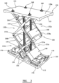
- FIGs. 1-10 show an exemplary scissor lift 100.
- the lift 100 comprises a base portion 110, which is arranged on the floor or another support surface in use, and a top portion 120, upon which a load can be placed in order to be lifted.
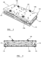
- the base and top portions 110/120 each take the form of substantially rectangular plate 111/121, with a flange 112/122 extending around the periphery of the plate 111/121 so as to effectively define a tray.
- the flanges 112/122 extend towards each other.
- the flange 112 extends upwardly from the plate 111
- the flange 122 extends downwardly from the plate 121.
- the top and base portions 110/120 are formed from sheet metal (e.g. aluminium).
- the flanges 112/122 extend substantially orthogonally from their respective plate 111/121.
- the top portion 120 comprises a plurality of braces 125.
- the braces 125 comprise a pair of longitudinal braces 125a, extending in parallel between the short sides of the rectangular plate 121, with cross braces 125b extending between the longitudinal braces 125a. Accordingly, the top portion 120 is prevented from flexing or distorting under load.
- the top portion 120 also comprises chain attachment points 126, to which the chains 151 (discussed in detail below) are attached.
- the top portion 120 furthermore comprises a plurality of mounting points 160.
- the mounting points 160 are connectable to a platform (not shown) or other piece of staging.
- the mounting points 160 protrude upwards from an upper surface 120a of the top portion 120.
- the top portion 120 comprises four mounting points 160, distributed at corners of a notional rectangle on the upper surface 120a.
- the structure of the mounting points 160 will be described in more detail below.
- the top portion 120 may also be provided with a plurality of holes (e.g. tapped holes) to which a platform may be attached. In some examples, the holes may serve as the attachment point for the mounting points 160 to the top portion 120.
- the holes may also be configured to receive lifting pins, to assist in the handling of the lift 100.
- the holes extend into a profile (i.e. a block of material) arranged on the underside of the top portion 120.
- the profile is for example formed of steel or aluminium.
- the base portion 110 comprises four longitudinal braces 115, extending in parallel between the short sides of the rectangular plate 111.
- the base portion 110 comprises a plurality of caster wheels 116, for example 4 caster wheels arranged proximate to the corners of the base portion 110.
- the casters 116 may be recessed from the underside of the base portion 110, such that only a portion of each wheel protrudes from the underside of the plate 111.
- the base portion 110 comprises a plurality of support legs 170.
- the support legs 170 are configured to be lowered down from the lower surface of the base portion 110, so as to raise the base portion 110. Accordingly, the wheels 116 become disengaged from the floor, thus preventing the base portion 110 from moving during use.
- the support legs 170 may be individually adjusted in order to allow the base portion 110 to be levelled.
- the wheels 116 can be raised and lowered, either to level the base portion 110 in its wheeled configuration, or to disengage the wheels 116 from the floor in favour of the support legs 170.
- the lift 100 further comprises a scissor assembly 130 that comprises pair of scissor subassemblies 130a, 130b, which extend between the top portion 110 and the base portion 120.
- the scissor subassemblies 130a/b are spaced apart, and are formed proximate to the longer edges or the rectangular plates 111/121.
- the scissor subassemblies 130 are parallel, and disposed to face each other (i.e. they are adjacent). Accordingly, the scissor subassemblies 130a/b are symmetrical in a notional vertical plane disposed between the subassemblies 130a/b, equidistant the assemblies 130a/b.
- Each scissor subassembly 130 comprises a first, lower scissor 131 and a second, upper scissor 132, so that the assemblies 130a/b each take the form of a double scissor.
- Each scissor 131/132 comprises a pair of crossed arms 133, rotatably connected at a pivot point 134 located at the meeting point of the arms 133.
- the lower ends of the arms 133 of lower scissors 131a/b are slidably attached to the base portion 110.
- the arms 133 of lower scissors 131a/b are also connected to the base portion 110 by virtue of secondary support arms 136.
- the arms 136 are pivotally connected to the lower scissor arms 133 at a position approximately 1 /4 of the way along their extent from the base portion 110.
- the arms 136 are also pivotally connected to the base portion 110 at a hinging point 113 between the sliding attachment points of the arms 133.
- the base portion 110 comprises tracks 114, each track 114 being arranged to receive a wheel 137 formed on the end of the arms 133 so as to support the sliding motion of the end of the arm 133 with respect to the base portion 110.
- the hinging portion 113 takes the form of a bar arranged to extend through apertures formed on the end of the support arms 136
- the upper ends of the arms 133 of the upper scissors 132a/b are slidably attached to the top portion 120 in a similar manner, as can be seen in FIG. 5 , which shows the underside of the top portion 120.
- the support arms 136 of the upper scissors 132 are connected to hinging point 123, and wheels 137 of the arms 133 of the upper scissors 132 are received in tracks 124.
- the upper ends of the arms 133 of the lower scissor 131 are pivotally connected to the lower ends of the arms 133 of the upper scissor 132 at pivot points 135.
- each scissor subassembly 130a/b is of the same size, and thus each scissor subassembly 130a/b, and thus the scissor assembly 130 as a whole, is symmetrical about a notional vertical line extending perpendicularly to the surface of the plates 111/121 and through the pivot points 134 of the scissors 131,132.
- the pivot point 134 may be located substantially equidistant from the ends of the arms 133. Accordingly, each scissor subassembly 130a/b may also be symmetrical about a notional horizontal line extending through the pivot points 135 of the scissors 131,132.
- At least one of, but preferably all of, the base portion 110, the top portion 120 and the scissor assembly 130 are formed of a lightweight material, preferably a lightweight metal, for example aluminium.
- at least one of, but preferably all of, the base portion 110, the top portion 120 and the scissor assembly 130 are formed by mechanical fastening.
- the flanges 112/122, plates 111/121, braces 115/125, arms 133/136 are attached to each other by nuts and bolts, or other suitable mechanical fasteners. Accordingly, the lift 100 as a whole is not welded, save for in respect of the construction of minor components such as the caster wheels 116. Avoiding using welding prevents the warping of components (e.g. during fabrication due to the sheet metal being affected by heat), ensuring that the lift 100 can be precisely manufactured and operated.
- the lift 100 further comprises a rigid chain lifting system 150.
- the rigid chain lifting system comprises a pair of rigid chains 151.
- the rigid chains 151 act as the lifting mechanism of the lift 100, taking the place of traditional hydraulic rams or the like.
- each chain 151 is connected to the underside of the top portion 120, and the other end of the chain is retained in a magazine 152 attached to the base portion 110.
- the chains 151 are movable between a retracted position, in which a substantial portion of each chain 151 is retained in the magazine 152 attached to the base portion 110, and an extended position, in which the chains 151 extend substantially vertically between the base portion 110 and the top portion 120.
- the structure of the chains 151 is such that the vertical chain is substantially rigid, so that it is able to support the weight of the top portion 120 and any load placed thereupon. Accordingly, the extension/retraction of the chain raises/lowers the top portion 120 between a lowermost or retracted position and an uppermost or extended positon.
- the scissor assembly 130 is able to effectively act as a guide only, rather than being substantially load-bearing, because the weight is supported by the chains 151.
- the chains 151 are SERAPID ® chains, such as SERAPID ® LinkLift 30 chains.
- the lifting system 150 comprises the magazines 152a/b for retaining respective rigid chains 151a/b in a substantially horizontal configuration.
- the system 150 further comprises a motor 153, gearing assembly 154 and axle 155.
- the axle 155 extends across the base portion 110 in a direction between the two longer edges of the plate 111 at a position approximately equidistant the short edges of the plate 111, though it will be understood that axle 155 need not be precisely equidistant from the short edges.
- Gearing portions comprising teeth (not shown) are formed at respective ends of the axle 155, which engage with respective rigid chains 151a/b. Accordingly, rotation of the axle 155 drives the chains 151 between the extended and retracted positions. Furthermore, the use of a common axle for both chains 151 ensures the chains 151 are driven synchronously.
- the motor 153 is configured to drive the axle 155.
- the motor 153 may drive the axle 155 via the gear assembly 154, as discussed below. However, it will be understood that in other examples the motor may drive the axle 155 directly.
- the motor 153 is an AC servo motor, driven by mains power received at port 153a.
- the servo motor delivers its maximum torque with a very low lag, which allows for precise control of the lift 100. This is highly advantageous in performance applications, in which the motion of the lift 100 must be synchronised with the music, the motion of other equipment and lighting effects.
- the motor 153 comprises a dynamic brake, which is operable to hold the axle 155 in a fixed position.
- the motor 153 comprises a primary encoder (not shown), which is operable to sense the extent to which the chains 151 have been extended or retracted based on the operation of the motor 153.
- the motor 153 is positioned transverse to the axle 155 at the opposite side of the axle to the magazines 152a/b, and thus the gearing assembly 154 is arranged between the motor 153 and the axle 155 in order to convert the drive of the motor 153 to rotate the axle 155.
- the gearing assembly 154 comprises a helical bevel gear, and acts as a reduction gear head.
- the rigid chain lifting system 150 comprises a safety brake 156.
- the safety brake 156 is arranged to, when activated, interfere with a further gearing portion of the axle 155.
- the safety brake 156 may be a substantially cylindrical body, which surrounds the further gearing portion, and which comprises projections configured to mesh with the gearing portion upon activation of the brake 156. Accordingly, the activated safety brake 156 prevents the rotation of the axle 155, thereby fixing the position of the top portion 120 with respect to the base portion 110.
- the safety brake 156 is arranged at one end of the axle 155.
- the safety brake 156 is configured to permit the rotation of the axle 155 upon receipt of power. In other words, in its default, unpowered state, the brake 156 prevents rotation of the axle 155, and thus motion of the chains 151.
- the rigid chain lifting system 150 is configured such that, when power is supplied to activate the motor 153 and move the chains 151, power is also provided to the safety brake 156 to permit rotation of the axle 155. When power ceases to be applied to the motor 153 (e.g. because the lift is in its desired position), and therefore also the safety brake 156, the safety brake 156 is activated thereby securely holding the platform in position.
- the rigid chain lifting system 150 further comprises a limit encoder assembly 157.
- the limit encoder assembly 157 is connected to the axle 155 by virtue of a belt assembly 157a, and accordingly is able to sense the rotation of the axle.
- the limit encoder assembly 157 fulfils two functions. Firstly, it acts as a secondary encoder, configured to sense the extent to which the chains have been extended or retracted based on the rotation of the axle 155.
- the rigid chain lifting system 150 is configured to compare the output of the primary encoder and the secondary encoder, for example using suitable software/hardware controller (not shown). If the output of the primary encoder and secondary encoder does not match (i.e. the encoders do not agree that the same amount of chain 151 has been deployed from the magazine 152), it is indicative of an error and the power is cut, thereby activating the safety brake 156.
- the limit encoder assembly 157 acts as a limit switch, automatically stopping the motor 153 when the chains 151 are either fully extended (and so the lift 100 is fully extended) or fully retracted (and so the lift 100 is fully retracted).
- the controller is configured to control the motor 153 in order to raise/lower the lift, in response to a control signal.
- the control signal may be received via cables connected to a port 153b of the motor. It will however be understood by those skilled in the art that other means of delivering the control signals are possible, including via wired or wireless communication links.
- the lift 100 is configured to receive the control signal from a suitable automation control system (500, FIG. 10 , such as an automation control console.
- a suitable automation control system 500, FIG. 10 , such as an automation control console.
- a system 1000 comprising the automation control system 500, which is configured to control one or more scissor lifts 100.
- the automation control system 500 may also be arranged to control various other stage equipment 400.
- the lift 100 further comprises a plurality of bracing plates 140 extending between corresponding locations on the respective scissor subassemblies 130a/b.
- bracing plates 140 are arranged on each scissor 131/132 at each side of the pivot point 134, to give a total of 8 plates.
- the plates 140 ensure that the scissor subassemblies 130a/b remain in their parallel, spaced apart configuration during operation of the lift 100.
- the bracing plates 140 are made of a stronger material than the scissor assembly 130, such as steel.
- the plates 140 are mechanically fastenable to the arms 133.
- the bracing plates 140 are substantially trapezoidal in cross-section.
- Each bracing plate 140 comprises an upper plate 141, angled side plates 142 extending obliquely downward from the upper plate 141 towards the arms 133, and flanges 143 connecting the side plates 142 to the arms 133.
- the upper plate 141 is parallel to, yet stands proud of, a notional plane extending between the point at which the flanges 143 connect to the arms 133 of the respective subassemblies 130a/b.
- the braces 140 comprise cutaway portions.
- the bracing plates 140 are configured to move to a nested configuration when the lift 100 is at its lowermost, fully retracted, position.
- the width of the upper plates 141 i.e. in the direction between the arms 133 progressively increases from a lowermost bracing plate 140 to an uppermost bracing plate 140, so that when the lift 100 is in its lowermost position, each bracing plate 140 is nested within the bracing plate 140 immediately above it.
- the lowermost of the bracing plates 140 forms a bridge over the lifting system 150. This allows for a low-profile base portion 110, thus decreasing the overall height of the lift 100 in its fully retracted position.
- the mounting portion 160 comprises a base portion 161, which is fixed to the upper surface 120a of the top portion 120 by virtue of a fastening means such as bolts 162a, washers 162b and nuts 162c.
- Stud portion 163 which comprises a plate 163a and a threaded projection 163b upstanding from the plate 163a, is disposed on top of base portion 161.
- Bolts 164 extend downwardly through elongate slots 163c formed in the stud portion 163 at either side of the projection 163b, then through elongate slots 161a formed in the base portion 161, before being received in sliding blocks 165.
- the sliding blocks 165 are retained in a channel 166 under the base portion 161, which permits motion of the blocks 165 in the direction of the slot 161a.
- the elongate slots 163c and 161a are substantially orthogonal to one another.
- the stud portion 163 When the bolts 164 are loosened, the stud portion 163 is permitted to slide with respect to the base portion 161 in a first direction in the horizontal plane (i.e. an x direction), guided by the slots 163c. In addition, the stud portion 163 is also permitted to move in a second direction in the horizontal plane, orthogonal to the first direction (i.e. a y direction), guided by the slots 161a. When the bolts 164 are tightened, the stud portion 163 becomes fixed with respect to the base portion 161.
- the mounting portion 160 comprises a pair of locknuts 167, threadable onto the projection 163b.
- the lower locknut 167a is threaded onto the projection 163b
- a platform or other staging (not shown) is mounted to the projection 163b (for example by extending through an aperture sized to allow passage of the projection 163b but not the locknut 167a), and then the upper locknut 167b is threaded onto the projection 163b, sandwiching the platform between the locknuts.
- the position of the lower locknut 167 may be adjusted (i.e. by threading it a longer or shorter distance along the extent of the projection 163b), thereby permitting adjustment of the position of the platform in a vertical plane, orthogonal to the x and y planes (i.e. a z direction).
- the overall dimensions of the scissor lift 100 are as follows.
- the base portion 110 and top portion 120 are 1m wide and 2m long.
- the lift 100 in its fully extended state is approximately 2.35m from the upper surface 121a of the top portion 120 to the lower surface of the base portion 120.
- the lift in its fully retracted state is 0.4m from the upper surface 121a of the top portion 120 to the lower surface of the base portion 120.
- the lift 100 weighs 530kg, and is rated for a 750kg safe working load.
- the scissor lift 100 is wheeled into position on caster wheels 116. Subsequently, the support legs 170 are deployed or the wheels 116 are raised to fix the lift 100 in positon. Power and control cables are then connected to the ports 153a/b.
- a platform (not shown) may be mounted to the mounting points 160. In some examples, however, the top surface 120a of the top portion 120 functions as the deck/platform, and so no additional platform is mounted to the lift 100.
- a control signal is sent to the motor 153, driving the motor 153 to turn the axle 155 (e.g. via gearing assembly 154) in a direction that drives the chains 151 out of their respective magazines 152.
- the links of the chains 151 move into a vertical configuration, they become rigid and so move the top portion 120 upwards and away from the base portion 110.
- power is also supplied to the safety brake 156, such that it permits rotation of the axle 155.
- the motor 153 deactivates and the safety brake 156 engages, thereby preventing motion of the chains 151 and holding the top portion 120 in position.
- each mounting point 160 allows for adjustment in the x/y/z directions, thereby facilitating levelling of the platform.
- the mounting points 160 may be discarded and support legs 170 used to level the lift 100 instead.
- the lift 100 In order to transport the lift 100, the lift 100 is fully retracted, whereupon it can be loaded into a container or lorry in a configuration that occupies minimal space.
- the passive scissor 200 comprises a base portion 210, which is arranged on the floor or another support surface in use, and a top portion 220, upon which a load can be placed in order to be lifted.
- the passive scissor 200 further comprises a scissor assembly 230, which extends between the top portion 210 and the base portion 220.
- the structure of the scissor assembly 230, and the means by which it couples to the top and base portions 220/210 are the same as or similar to one of the scissor subassemblies 130a/b of the scissor lift 100.
- the base portion 210 comprises support legs 270 the same as or similar to the support legs 170 of the scissor lift 100.
- the top portion 220 comprises mounting portions 260, the same as or similar to the mounting portions 160 of the scissor lift 100. Accordingly, for clarity, the description of these elements is not repeated.
- the passive scissor 200 has the same length (e.g. 2m) as the scissor lift 100. However, the passive scissor is substantially narrower (e.g.0.15m wide).
- the passive scissor 200 is coupled to a scissor lift 100, such that the rise and fall of the scissor lift 100 also causes the rise and fall of the passive scissor 200.
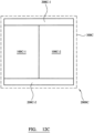
- Example stage assembly arrangements comprising scissor lifts 100 and passive scissors 200 will now be discussed with reference to FIG. 12A-C .
- FIG 12A shows a stage assembly 2000A in schematic plan view.
- the assembly 2000A comprises a scissor lift 100A and a passive scissor 200A.
- a long side of the passive scissor 200A is attached to one of the short side edges of the scissor lift 100A, so as to form a T shape.
- Each of the passive scissor 200A and scissor lift 100A may comprise apertures to receive mechanical fastenings for securing the devices to one another.
- the flanges of top and base portions of each device may comprise apertures.
- the flanges may be provided with a plurality of apertures disposed at differing locations around the flanges, so as to facilitate coupling the passive scissor 200A and scissor lift 100A to one another, and to numerous other accessories, in various ways.
- the scissor lift 100A and passive scissor 200A support a platform 300A. As the scissor lift 100A rises and falls, the passive scissor 200A directly coupled thereto rises and falls. Accordingly, the passive scissor 200A effectively provides a means for stabilising the platform 300A, and transmitting the lifting motion of the lift 100A to a wider area.
- FIG. 12B shows an example stage assembly 2000B, similar to the stage assembly 2000A of FIG. 12A .
- four passive scissors 200B-1, 200-B2, 200B-3, 200B-4 are coupled to the scissor lift 100B.
- Two of the passive scissors 200B-1, 200B-2 are coupled to the short side of the scissor lift 100B, such that their long sides abut the short side. Accordingly, the overall width of the area supported is larger than in the stage assembly 2000B.
- two further passive scissors 200B-3, 200B-4 are respectively coupled to opposing longer sides of the scissor lift 100B.
- each passive scissor 200B-3, 200B-4 is arranged such that approximately half of its longitudinal extent coincides with the scissor 100B, thus extending the overall length of the area supported by the stage assembly 2000B.
- FIG. 12C shows an example stage assembly 2000C comprising two scissor lifts 100C-1, 100C-2 and two passive scissors 200C-1, 200C-2.
- Each passive scissor 200C is arranged to connect the short edges of the two lifts 100C. Accordingly, the lifts 100C act in tandem and greater stability is provided.
- each scissor assembly could comprise a single scissor, or more than two scissors.
- the scissor lift may comprise more than two scissor subassemblies.
- the scissor subassemblies need not be disposed in parallel or adjacent to one another. Whilst the examples shown comprise base portions and top portions of matching dimensions, it will be understood that these may differ in dimensions. It will be understood that in some examples, one or more the components (e.g. base portion, top portion, scissors) may be formed of or comprise steel or other heavier metals, in addition to, or instead of, aluminium.
- the top and/or bottom portions 120/110 may comprise access panels or hatches, for cable management and to facilitate access to the rigid chain lifting system 150. For example a hatch may be provided on the top plate 121.
- the above-described scissor lift provides an advantageously lightweight and compact lift.
- the use of a rigid chain lifting system means that the scissors are provided for guidance rather than applying load, and thus can be fabricated from lighter, less strong material.
- the use of an AC servo motor allows for precise control of the lift, allowing for synchronous movement of multiple lifts during performances.
- the lift is fabricated substantially without welding, ensuring that the components do not warp during manufacturing and facilitating easy repair and fabrication.
- the above-describe scissor lift can be operated in conjunction with one or more passive scissors, utilising the lifting power of the scissor lift to stably lift loads of differing sizes and shape.
- the scissor lift and passive scissors are advantageously modular, and can be deployed in many different configurations depending on the requirements of the show.
- the scissor lift and passive scissors retract into a highly compact arrangement, thereby saving on travel costs.
Landscapes
- Engineering & Computer Science (AREA)
- Mechanical Engineering (AREA)
- General Engineering & Computer Science (AREA)
- Structural Engineering (AREA)
- Architecture (AREA)
- Life Sciences & Earth Sciences (AREA)
- Geology (AREA)
- Civil Engineering (AREA)
- Handcart (AREA)
Claims (18)
- eine Bühnenanordnung, umfassend:
eine Scherenhebebühne (100), umfassend:einen Basisabschnitt (110), der so konfiguriert ist, dass er auf einem Boden oder einer anderen Stützfläche abgestützt werden kann;einen oberen Abschnitt (120), der dazu konfiguriert ist, eine Plattform (300) zu stützen;eine Scherenarmanordnung (130), die den Basisabschnitt (110) und den oberen Abschnitt (120) verbindet, wobei die Scherenarmanordnung (130) zwei Unteranordnungen (130a, 130b) umfasst und jede Unteranordnung mindestens ein Paar gekreuzter Arme (133) umfasst, die an einem Drehpunkt (134) verbunden sind, um eine Schere (131, 132) zu bilden;ein Hebesystem mit starrer Kette (150), das eine starre Kette (151) umfasst, die den Basisabschnitt (110) und den oberen Abschnitt (120) verbindet, wobei die Scherenhebebühne (100) so konfiguriert ist, dass das Ausfahren und Einfahren der starren Kette (151) dazu führt, dass der obere Abschnitt (120) in Bezug auf den Basisabschnitt (110) angehoben und abgesenkt wird;und gekennzeichnet durcheine Vielzahl von Versteifungsplatten (140), die zwischen entsprechenden Stellen auf den jeweiligen Unteranordnungen (130a, 130b) verlaufen, wobei die Versteifungsplatten (140) jeweils eine obere Platte (141) und abgewinkelte Seitenplatten (142) umfassen, die von der oberen Platte (121) schräg nach unten in Richtung der Arme (133) der jeweiligen Scherenarmunteranordnungen verlaufen, und Flansche (143) die die abgewinkelten Seitenplatten (142) mit den Scherenarmunteranordnungen (130a, 130b) verbinden;wobei die Breite der oberen Platten (141) in einer Richtung zwischen den Armen (133) der jeweiligen Scherenarmunteranordnungen von einer untersten Versteifungsplatte zu einer obersten Versteifungsplatte fortschreitend zunimmt, so dass, wenn sich die Hebebühne (100) in einer untersten Position befindet, wobei jede Versteifungsplatte in der unmittelbar darüber liegenden Versteifungsplatte verschachtelt ist;wobei die obersten Arme (133) jeder Unteranordnung (130a, 130b) einen Stützarm (136) umfassen, der schwenkbar zwischen dem jeweiligen obersten Arm (133) und dem oberen Abschnitt (120) angebracht ist, und wobei mindestens einer der untersten Arme (133) jeder Unteranordnung (130a, 130b) einen Stützarm (136) umfasst, der schwenkbar zwischen dem jeweiligen untersten Arm (133) und dem Basisabschnitt (110) angebracht ist. - Bühnenanordnung nach Anspruch 1, wobei das Hebesystem mit starrer Kette (150) ein Paar starrer Ketten (151) umfasst.
- Bühnenanordnung nach einem der vorstehenden Ansprüche, wobei das Hebesystem mit starrer Kette (150) einen Wechselstrom-Servomotor (153) zum Ausfahren und Einfahren der starren Kette (151) umfasst, wobei der Motor (153) wahlweise zum Antreiben einer Achse (155) konfiguriert ist und die Achse (155) einen Kettenzahnradabschnitt umfasst, der zum Eingreifen in die starre Kette (151) angeordnet ist.
- Bühnenanordnung nach Anspruch 3, wobei das Hebesystem mit starrer Kette (150) eine Sicherheitsbremse (156) umfasst, die so konfiguriert ist, dass sie bei Stromzufuhr zum Wechselstrom-Servomotor (153) gelöst und bei Unterbrechung der Stromzufuhr zum Wechselstrom-Servomotor (153) aktiviert wird, wobei das Hebesystem mit starrer Kette (150) optional umfasst:einen primären Codierer, der dazu konfiguriert ist, basierend auf der Bewegung des Motors (153) das Ausmaß zu bestimmen, in dem die starre Kette (151) eingesetzt wird;einen sekundären Codierer (157), der dazu konfiguriert ist, basierend auf der Bewegung der Achse (155) das Ausmaß zu bestimmen, in dem die starre Kette (151) eingesetzt wird; unddas Hebesystem mit starrer Kette (150) so konfiguriert ist, dass es die Sicherheitsbremse (156) aktiviert, wenn die Ausgabe des primären und des sekundären Codierer (157) anzeigt, dass die starre Kette (151) in einem unterschiedlichen Ausmaß ausgefahren ist.
- Bühnenanordnung nach einem der vorstehenden Ansprüche, wobei das Hebesystem mit starrer Kette (150) im Basisabschnitt (110) angeordnet ist.
- Bühnenanordnung nach einem der vorstehenden Ansprüche, wobei: i) einer oder mehrere der Basisabschnitte (110), der obere Abschnitt (120) und die Scherenarmanordnung (130) Aluminium umfassen; und/oder ii) der Basisabschnitt (110) und/oder der obere Abschnitt (120) mit mechanischen Befestigungselementen mit der Scherenarmanordnung (130) verbunden sind; und/oder iii) eines oder mehrere von Basisabschnitt (110), Oberteil (120) und/oder Scherenarmanordnung (130) Komponenten umfassen, die mit mechanischen Befestigungselementen verbunden sind.
- Bühnenanordnung nach einem der vorstehenden Ansprüche, wobei die Scherenarmunteranordnungen (130a, 130b) jeweils zwei Scheren (131, 132) umfassen, so dass eine Doppelschere entsteht.
- Bühnenanordnung nach Anspruch 7, wobei die Scherenarmunteranordnungen (130a, 130b) in einer gedachten vertikalen Ebene symmetrisch sind, die durch Drehpunkte der Scheren (131,132) verläuft.
- Bühnenanordnung nach Anspruch 8, wobei die starre Kette (151) zwischen den Scherenarmunteranordnungen (130a, 130b) auf der gedachten vertikalen Ebene angeordnet ist.
- Bühnenanordnung nach einem der vorstehenden Ansprüche, wobei der obere Abschnitt (120) eine Vielzahl von Befestigungspunkten (160) umfasst, die für die Befestigung der Plattform (300) daran konfiguriert sind.
- Bühnenanordnung nach einem der vorstehenden Ansprüche, wobei die Höhe der Scherenhebebühne (100) im vollständig eingefahrenen Zustand weniger als 1 m beträgt.
- Bühnensystem nach einem der vorstehenden Ansprüche, umfassend ein Automatisierungssteuerungssystem (500), das zur Fernsteuerung der Scherenhebebühne (100) konfiguriert ist.
- Verfahren zum Betreiben einer Bühnenanordnung nach einem der Ansprüche 1 bis 12, wobei das Verfahren umfasst:• Betreiben des Hebesystems mit starrer Kette (150), um ein Ausfahren der starren Kette (151) und ein Anheben des oberen Abschnitts (120) in Bezug auf den Basisabschnitt (110) zu bewirken; und/oder• Betreiben des Hebesystems mit starrer Kette (150), um ein Einfahren der starren Kette (151) und ein Absenken des oberen Abschnitts (120) in Bezug auf den Basisabschnitt (110) zu bewirken.
- Verfahren nach Anspruch 13, wobei beim Betrieb der Bühnenanordnung Künstler, Musikausrüstung, Beleuchtungsausrüstung oder andere Bühnenausrüstung auf den oberen Abschnitt (120) befördert werden.
- Verfahren nach Anspruch 13 oder Anspruch 14, wobei der Schritt des Betreibens des Hebesystems mit starrer Kette (150), um ein Ausfahren der starren Kette (151) zu bewirken, das Senden eines Steuersignals an einen Motor (153) umfasst, wodurch der Motor (153) angetrieben wird, um eine Achse (155) in eine Richtung zu drehen, die die starre Kette (151) aus einem Magazin (152) in eine vertikale Konfiguration treibt.
- Verfahren nach Anspruch 15, wobei der Schritt des Betätigens des Hebesystems mit starrer Kette (150), um ein Ausfahren der starren Kette (151) zu bewirken, das Zuführen von Energie zu einer Sicherheitsbremse (156) umfasst, bis sich der obere Abschnitt (120) in einer gewünschten Position befindet, wobei an diesem Punkt die Sicherheitsbremse (156) aktiviert wird, um eine Bewegung der starren Kette (151) zu verhindern und den oberen Abschnitt (120) in Position zu halten.
- Verfahren nach einem der Ansprüche 13 bis 16, wobei der Schritt des Betreibens des Hebesystems mit starrer Kette (150), um das Einfahren der starren Kette (151) zu bewirken, das Senden eines Steuersignals an den Motor (153) umfasst, wodurch der Motor (153) angetrieben wird, um die Achse (155) in eine Richtung zu drehen, die die starre Kette (151) in das Magazin (152) treibt.
- Verfahren nach einem der Ansprüche 13 bis 17, ferner umfassend den Schritt des Anbringens einer Plattform (300) am oberen Abschnitt (120) der Scherenhebebühne (100).
Applications Claiming Priority (2)
| Application Number | Priority Date | Filing Date | Title |
|---|---|---|---|
| GBGB1804268.9A GB201804268D0 (en) | 2018-03-16 | 2018-03-16 | Lift |
| PCT/GB2019/050738 WO2019175601A1 (en) | 2018-03-16 | 2019-03-15 | Lift |
Publications (3)
| Publication Number | Publication Date |
|---|---|
| EP3752448A1 EP3752448A1 (de) | 2020-12-23 |
| EP3752448B1 true EP3752448B1 (de) | 2024-12-04 |
| EP3752448C0 EP3752448C0 (de) | 2024-12-04 |
Family
ID=62017903
Family Applications (1)
| Application Number | Title | Priority Date | Filing Date |
|---|---|---|---|
| EP19713162.6A Active EP3752448B1 (de) | 2018-03-16 | 2019-03-15 | Hebevorrichtung |
Country Status (4)
| Country | Link |
|---|---|
| US (1) | US12049395B2 (de) |
| EP (1) | EP3752448B1 (de) |
| GB (1) | GB201804268D0 (de) |
| WO (1) | WO2019175601A1 (de) |
Families Citing this family (12)
| Publication number | Priority date | Publication date | Assignee | Title |
|---|---|---|---|---|
| FR3072374B1 (fr) * | 2017-10-17 | 2022-12-30 | Serapid France | Dispositif elevatoire par poussee |
| CN110625351B (zh) * | 2019-09-28 | 2022-06-07 | 徐州徐工基础工程机械有限公司 | 水平定向钻机动力头自拆卸方法 |
| CN111479435B (zh) * | 2020-04-17 | 2021-05-18 | 盐城工业职业技术学院 | 一种基于计算机网络机房控制器的升降装置 |
| CN112279145B (zh) * | 2020-11-20 | 2025-05-02 | 优易电缆(张家港)有限公司 | 一种升降平台 |
| CN112376436A (zh) * | 2020-11-24 | 2021-02-19 | 刘涛 | 一种桥梁施工用桥梁支撑调节装置 |
| CN215701538U (zh) * | 2021-01-15 | 2022-02-01 | 浙江金华文瑞机电有限公司 | 一种自动工位升降平台 |
| CN113618425B (zh) * | 2021-08-03 | 2022-08-05 | 北京交通大学 | 一种可折叠的并联机构及其应用 |
| CN114992435A (zh) * | 2022-02-24 | 2022-09-02 | 北京固鸿科技有限公司 | 用于辐射成像系统的升降机构和辐射成像系统 |
| CN114894080A (zh) * | 2022-04-25 | 2022-08-12 | 宣城市三番科技有限公司 | 一种剪刀叉高度的计量方法 |
| CN115724377A (zh) * | 2022-12-09 | 2023-03-03 | 北京特种机械研究所 | 一种伸缩扩展平台及使用其的agv小车 |
| CN118723889B (zh) * | 2024-09-03 | 2024-12-20 | 浙江苏源电力工程有限公司 | 升降式电力电气设备检修平台 |
| CN119754609B (zh) * | 2025-03-04 | 2025-05-30 | 江苏金银杏舞台设备有限公司 | 一种舞台升降机防倾倒机构 |
Citations (2)
| Publication number | Priority date | Publication date | Assignee | Title |
|---|---|---|---|---|
| US3341042A (en) * | 1966-12-16 | 1967-09-12 | American Sugar | Elevator control system |
| WO2006112857A2 (en) * | 2004-05-17 | 2006-10-26 | Allan Pavlick | Device and system for lifting a motor vehicle |
Family Cites Families (26)
| Publication number | Priority date | Publication date | Assignee | Title |
|---|---|---|---|---|
| US2937852A (en) * | 1956-10-29 | 1960-05-24 | Jesse E Clarke | Lift device |
| DE1166991B (de) * | 1962-10-26 | 1964-04-02 | Trepel K G Maschinenfabrik | Hydraulisch angetriebener Hebetisch |
| US3350065A (en) * | 1966-10-24 | 1967-10-31 | Standard Mfg Company Inc | Scissor-type linear actuator with high extension ratio and selectable extension rateand power requirement |
| US3628771A (en) * | 1969-07-28 | 1971-12-21 | Haakon G Egeland | Scissors-type lifting linkage elevator |
| BE791776A (fr) * | 1972-02-24 | 1973-03-16 | Trepel Ag | Table relevable a parallelogramme deformable |
| US20080105498A1 (en) * | 2006-06-12 | 2008-05-08 | Genie Industries, Inc. | Joint assembly and related methods |
| JP2009001377A (ja) * | 2007-06-21 | 2009-01-08 | Tsubakimoto Chain Co | 噛合チェーン式昇降装置 |
| JP4723538B2 (ja) | 2007-06-21 | 2011-07-13 | 株式会社椿本チエイン | 噛合チェーン式昇降装置 |
| JP5197155B2 (ja) | 2008-05-23 | 2013-05-15 | 株式会社椿本チエイン | 噛合チェーン式昇降装置 |
| JP2010001129A (ja) | 2008-06-20 | 2010-01-07 | Tsubakimoto Chain Co | 噛合チェーン式昇降装置 |
| IT1391626B1 (it) | 2008-07-23 | 2012-01-11 | A C R Di Romano Livio & C S N C | "sollevatore a pantografo" |
| JP4662503B2 (ja) | 2008-12-09 | 2011-03-30 | 株式会社椿本チエイン | 噛合チェーン |
| JP4662504B2 (ja) | 2009-03-09 | 2011-03-30 | 株式会社椿本チエイン | 昇降駆動用噛合チェーン |
| US20120272584A1 (en) * | 2011-04-29 | 2012-11-01 | Hitech Stages, Ltd. | Rapidly deployable stage system |
| JP2013212904A (ja) * | 2012-04-02 | 2013-10-17 | Tsubakimoto Chain Co | 噛合チェーン式昇降装置 |
| CN103552948B (zh) | 2013-10-16 | 2016-01-13 | 湖北华昌达智能装备股份有限公司 | 一种滑板用剪叉式升降台及滑板和滑板输送线 |
| US10081522B2 (en) * | 2014-10-17 | 2018-09-25 | Vehicle Service Group, Llc | Hydraulic synchronizer |
| CN204801748U (zh) | 2015-07-15 | 2015-11-25 | 王俊 | 升降搬运装置 |
| JP6455672B2 (ja) | 2015-08-17 | 2019-01-23 | 株式会社ダイフク | リフター |
| CN205637803U (zh) | 2016-04-21 | 2016-10-12 | 江苏英孚机器人有限公司 | 升降桅杆 |
| DE202016102566U1 (de) * | 2016-05-12 | 2017-08-16 | Gerhard Finkbeiner | Fahrschienenhebebühne für Fahrzeuge sowie Hubeinrichtung für Fahrschienenhebebühne |
| CN206016334U (zh) | 2016-08-05 | 2017-03-15 | 广州颂拓专用设备有限公司 | 刚性链升降舞台 |
| CN106276691B (zh) | 2016-08-23 | 2018-08-07 | 安徽恒诺机电科技有限公司 | 机电升降系统 |
| CN206328091U (zh) | 2016-12-23 | 2017-07-14 | 湖北国瑞智能装备股份有限公司 | 一种推杆链条升降机 |
| CN206938916U (zh) * | 2017-07-10 | 2018-01-30 | 东风设计研究院有限公司 | 一种车身从橇体转吊具的内置式升降转接装置 |
| JP6838708B2 (ja) * | 2017-08-07 | 2021-03-03 | 株式会社ダイフク | 昇降自在なワーク支持装置 |
-
2018
- 2018-03-16 GB GBGB1804268.9A patent/GB201804268D0/en not_active Ceased
-
2019
- 2019-03-15 WO PCT/GB2019/050738 patent/WO2019175601A1/en not_active Ceased
- 2019-03-15 US US16/981,459 patent/US12049395B2/en active Active
- 2019-03-15 EP EP19713162.6A patent/EP3752448B1/de active Active
Patent Citations (2)
| Publication number | Priority date | Publication date | Assignee | Title |
|---|---|---|---|---|
| US3341042A (en) * | 1966-12-16 | 1967-09-12 | American Sugar | Elevator control system |
| WO2006112857A2 (en) * | 2004-05-17 | 2006-10-26 | Allan Pavlick | Device and system for lifting a motor vehicle |
Also Published As
| Publication number | Publication date |
|---|---|
| EP3752448A1 (de) | 2020-12-23 |
| GB201804268D0 (en) | 2018-05-02 |
| EP3752448C0 (de) | 2024-12-04 |
| WO2019175601A1 (en) | 2019-09-19 |
| US12049395B2 (en) | 2024-07-30 |
| US20210070591A1 (en) | 2021-03-11 |
Similar Documents
| Publication | Publication Date | Title |
|---|---|---|
| EP3752448B1 (de) | Hebevorrichtung | |
| US4567821A (en) | Apparatus for assembling wooden trusses and the like | |
| KR102013575B1 (ko) | 유압식 갠트리 크레인 | |
| US10703591B2 (en) | Loading platform | |
| US10662658B2 (en) | Scaffold for supporting a working platform for bridges | |
| US9512629B2 (en) | Mobile stage framework and method of handling | |
| JP4962252B2 (ja) | 橋梁の架設工法および架設装置 | |
| JP2006315864A (ja) | 重量物持上げ用ラティスブームクレーン | |
| US6345943B1 (en) | Transformer trailer | |
| US11484117B2 (en) | Movable platform of a suspended storage apparatus | |
| CA2920075C (en) | Scaffold | |
| JP3602541B2 (ja) | 枠組み又は任意には該枠組み上に載っている建物の一部分と一緒の枠組みの昇降装置 | |
| US20210023733A1 (en) | Sawmill | |
| KR20130018421A (ko) | 모노레일식 자립이동형 갠트리 크레인 | |
| CN110562856B (zh) | 重物的起重装置以及起重搬运方法 | |
| US20110120801A1 (en) | Access system, a method of assembly, a support element, a guiding element and an extruded profile for the system | |
| CN106121253A (zh) | 安装构件用可调式辅助安装装置及方法 | |
| KR102289196B1 (ko) | 겐트리 크레인 | |
| US20090071751A1 (en) | Portable aerial platform | |
| CN218595965U (zh) | 龙门吊装系统 | |
| CN222757751U (zh) | 一种起重辅助装置 | |
| EP0298924B1 (de) | Vorrichtung zum Erhöhen der Lagerkapazität eines Raumes und insbesondere einer Wagengarage | |
| WO2002014144A1 (en) | Vessel provided with a device for removing and/or installing a sub-structure of a drilling or production platform | |
| JP7591789B2 (ja) | レール両側積卸機 | |
| WO2024223013A1 (en) | Apparatus and method for transporting a wind turbine component to and/or at an offshore wind turbine |
Legal Events
| Date | Code | Title | Description |
|---|---|---|---|
| STAA | Information on the status of an ep patent application or granted ep patent |
Free format text: STATUS: UNKNOWN |
|
| STAA | Information on the status of an ep patent application or granted ep patent |
Free format text: STATUS: THE INTERNATIONAL PUBLICATION HAS BEEN MADE |
|
| PUAI | Public reference made under article 153(3) epc to a published international application that has entered the european phase |
Free format text: ORIGINAL CODE: 0009012 |
|
| STAA | Information on the status of an ep patent application or granted ep patent |
Free format text: STATUS: REQUEST FOR EXAMINATION WAS MADE |
|
| 17P | Request for examination filed |
Effective date: 20200917 |
|
| AK | Designated contracting states |
Kind code of ref document: A1 Designated state(s): AL AT BE BG CH CY CZ DE DK EE ES FI FR GB GR HR HU IE IS IT LI LT LU LV MC MK MT NL NO PL PT RO RS SE SI SK SM TR |
|
| AX | Request for extension of the european patent |
Extension state: BA ME |
|
| DAV | Request for validation of the european patent (deleted) | ||
| DAX | Request for extension of the european patent (deleted) | ||
| STAA | Information on the status of an ep patent application or granted ep patent |
Free format text: STATUS: EXAMINATION IS IN PROGRESS |
|
| 17Q | First examination report despatched |
Effective date: 20220905 |
|
| GRAP | Despatch of communication of intention to grant a patent |
Free format text: ORIGINAL CODE: EPIDOSNIGR1 |
|
| STAA | Information on the status of an ep patent application or granted ep patent |
Free format text: STATUS: GRANT OF PATENT IS INTENDED |
|
| INTG | Intention to grant announced |
Effective date: 20240626 |
|
| GRAS | Grant fee paid |
Free format text: ORIGINAL CODE: EPIDOSNIGR3 |
|
| GRAA | (expected) grant |
Free format text: ORIGINAL CODE: 0009210 |
|
| STAA | Information on the status of an ep patent application or granted ep patent |
Free format text: STATUS: THE PATENT HAS BEEN GRANTED |
|
| AK | Designated contracting states |
Kind code of ref document: B1 Designated state(s): AL AT BE BG CH CY CZ DE DK EE ES FI FR GB GR HR HU IE IS IT LI LT LU LV MC MK MT NL NO PL PT RO RS SE SI SK SM TR |
|
| REG | Reference to a national code |
Ref country code: GB Ref legal event code: FG4D |
|
| REG | Reference to a national code |
Ref country code: CH Ref legal event code: EP |
|
| REG | Reference to a national code |
Ref country code: DE Ref legal event code: R096 Ref document number: 602019062913 Country of ref document: DE |
|
| REG | Reference to a national code |
Ref country code: IE Ref legal event code: FG4D |
|
| U01 | Request for unitary effect filed |
Effective date: 20241218 |
|
| U07 | Unitary effect registered |
Designated state(s): AT BE BG DE DK EE FI FR IT LT LU LV MT NL PT RO SE SI Effective date: 20250102 |
|
| U20 | Renewal fee for the european patent with unitary effect paid |
Year of fee payment: 7 Effective date: 20250205 |
|
| PG25 | Lapsed in a contracting state [announced via postgrant information from national office to epo] |
Ref country code: HR Free format text: LAPSE BECAUSE OF FAILURE TO SUBMIT A TRANSLATION OF THE DESCRIPTION OR TO PAY THE FEE WITHIN THE PRESCRIBED TIME-LIMIT Effective date: 20241204 |
|
| PG25 | Lapsed in a contracting state [announced via postgrant information from national office to epo] |
Ref country code: ES Free format text: LAPSE BECAUSE OF FAILURE TO SUBMIT A TRANSLATION OF THE DESCRIPTION OR TO PAY THE FEE WITHIN THE PRESCRIBED TIME-LIMIT Effective date: 20241204 |
|
| PG25 | Lapsed in a contracting state [announced via postgrant information from national office to epo] |
Ref country code: NO Free format text: LAPSE BECAUSE OF FAILURE TO SUBMIT A TRANSLATION OF THE DESCRIPTION OR TO PAY THE FEE WITHIN THE PRESCRIBED TIME-LIMIT Effective date: 20250304 |
|
| PG25 | Lapsed in a contracting state [announced via postgrant information from national office to epo] |
Ref country code: GR Free format text: LAPSE BECAUSE OF FAILURE TO SUBMIT A TRANSLATION OF THE DESCRIPTION OR TO PAY THE FEE WITHIN THE PRESCRIBED TIME-LIMIT Effective date: 20250305 |
|
| PGFP | Annual fee paid to national office [announced via postgrant information from national office to epo] |
Ref country code: GB Payment date: 20250102 Year of fee payment: 7 |
|
| PG25 | Lapsed in a contracting state [announced via postgrant information from national office to epo] |
Ref country code: RS Free format text: LAPSE BECAUSE OF FAILURE TO SUBMIT A TRANSLATION OF THE DESCRIPTION OR TO PAY THE FEE WITHIN THE PRESCRIBED TIME-LIMIT Effective date: 20250304 |
|
| PG25 | Lapsed in a contracting state [announced via postgrant information from national office to epo] |
Ref country code: SM Free format text: LAPSE BECAUSE OF FAILURE TO SUBMIT A TRANSLATION OF THE DESCRIPTION OR TO PAY THE FEE WITHIN THE PRESCRIBED TIME-LIMIT Effective date: 20241204 |
|
| PG25 | Lapsed in a contracting state [announced via postgrant information from national office to epo] |
Ref country code: PL Free format text: LAPSE BECAUSE OF FAILURE TO SUBMIT A TRANSLATION OF THE DESCRIPTION OR TO PAY THE FEE WITHIN THE PRESCRIBED TIME-LIMIT Effective date: 20241204 |
|
| PG25 | Lapsed in a contracting state [announced via postgrant information from national office to epo] |
Ref country code: IS Free format text: LAPSE BECAUSE OF FAILURE TO SUBMIT A TRANSLATION OF THE DESCRIPTION OR TO PAY THE FEE WITHIN THE PRESCRIBED TIME-LIMIT Effective date: 20250404 |
|
| PG25 | Lapsed in a contracting state [announced via postgrant information from national office to epo] |
Ref country code: SK Free format text: LAPSE BECAUSE OF FAILURE TO SUBMIT A TRANSLATION OF THE DESCRIPTION OR TO PAY THE FEE WITHIN THE PRESCRIBED TIME-LIMIT Effective date: 20241204 |
|
| PG25 | Lapsed in a contracting state [announced via postgrant information from national office to epo] |
Ref country code: CZ Free format text: LAPSE BECAUSE OF FAILURE TO SUBMIT A TRANSLATION OF THE DESCRIPTION OR TO PAY THE FEE WITHIN THE PRESCRIBED TIME-LIMIT Effective date: 20241204 |
|
| PLBE | No opposition filed within time limit |
Free format text: ORIGINAL CODE: 0009261 |
|
| STAA | Information on the status of an ep patent application or granted ep patent |
Free format text: STATUS: NO OPPOSITION FILED WITHIN TIME LIMIT |
|
| PG25 | Lapsed in a contracting state [announced via postgrant information from national office to epo] |
Ref country code: MC Free format text: LAPSE BECAUSE OF FAILURE TO SUBMIT A TRANSLATION OF THE DESCRIPTION OR TO PAY THE FEE WITHIN THE PRESCRIBED TIME-LIMIT Effective date: 20241204 |
|
| REG | Reference to a national code |
Ref country code: CH Ref legal event code: L10 Free format text: ST27 STATUS EVENT CODE: U-0-0-L10-L00 (AS PROVIDED BY THE NATIONAL OFFICE) Effective date: 20251015 |
|
| REG | Reference to a national code |
Ref country code: CH Ref legal event code: H13 Free format text: ST27 STATUS EVENT CODE: U-0-0-H10-H13 (AS PROVIDED BY THE NATIONAL OFFICE) Effective date: 20251024 |
|
| 26N | No opposition filed |
Effective date: 20250905 |