EP3752373B1 - Entlüftungsstopfen für eine nabenkappe - Google Patents
Entlüftungsstopfen für eine nabenkappe Download PDFInfo
- Publication number
- EP3752373B1 EP3752373B1 EP19751202.3A EP19751202A EP3752373B1 EP 3752373 B1 EP3752373 B1 EP 3752373B1 EP 19751202 A EP19751202 A EP 19751202A EP 3752373 B1 EP3752373 B1 EP 3752373B1
- Authority
- EP
- European Patent Office
- Prior art keywords
- vent plug
- base
- vent
- cavity
- cover
- Prior art date
- Legal status (The legal status is an assumption and is not a legal conclusion. Google has not performed a legal analysis and makes no representation as to the accuracy of the status listed.)
- Active
Links
Images


Classifications
-
- B—PERFORMING OPERATIONS; TRANSPORTING
- B60—VEHICLES IN GENERAL
- B60B—VEHICLE WHEELS; CASTORS; AXLES FOR WHEELS OR CASTORS; INCREASING WHEEL ADHESION
- B60B7/00—Wheel cover discs, rings, or the like, for ornamenting, protecting, venting, or obscuring, wholly or in part, the wheel body, rim, hub, or tyre sidewall, e.g. wheel cover discs, wheel cover discs with cooling fins
- B60B7/0013—Hub caps
- B60B7/002—Hub caps being of the ventilated type
-
- B—PERFORMING OPERATIONS; TRANSPORTING
- B60—VEHICLES IN GENERAL
- B60B—VEHICLE WHEELS; CASTORS; AXLES FOR WHEELS OR CASTORS; INCREASING WHEEL ADHESION
- B60B7/00—Wheel cover discs, rings, or the like, for ornamenting, protecting, venting, or obscuring, wholly or in part, the wheel body, rim, hub, or tyre sidewall, e.g. wheel cover discs, wheel cover discs with cooling fins
- B60B7/04—Wheel cover discs, rings, or the like, for ornamenting, protecting, venting, or obscuring, wholly or in part, the wheel body, rim, hub, or tyre sidewall, e.g. wheel cover discs, wheel cover discs with cooling fins built-up of several main parts
-
- B—PERFORMING OPERATIONS; TRANSPORTING
- B60—VEHICLES IN GENERAL
- B60B—VEHICLE WHEELS; CASTORS; AXLES FOR WHEELS OR CASTORS; INCREASING WHEEL ADHESION
- B60B2900/00—Purpose of invention
- B60B2900/10—Reduction of
- B60B2900/141—Corrosions
-
- B—PERFORMING OPERATIONS; TRANSPORTING
- B60—VEHICLES IN GENERAL
- B60B—VEHICLE WHEELS; CASTORS; AXLES FOR WHEELS OR CASTORS; INCREASING WHEEL ADHESION
- B60B2900/00—Purpose of invention
- B60B2900/50—Improvement of
- B60B2900/511—Sealing
- B60B2900/5112—Sealing against dust or dirt
-
- B—PERFORMING OPERATIONS; TRANSPORTING
- B60—VEHICLES IN GENERAL
- B60B—VEHICLE WHEELS; CASTORS; AXLES FOR WHEELS OR CASTORS; INCREASING WHEEL ADHESION
- B60B2900/00—Purpose of invention
- B60B2900/50—Improvement of
- B60B2900/511—Sealing
- B60B2900/5114—Sealing against humidity or water
-
- B—PERFORMING OPERATIONS; TRANSPORTING
- B60—VEHICLES IN GENERAL
- B60B—VEHICLE WHEELS; CASTORS; AXLES FOR WHEELS OR CASTORS; INCREASING WHEEL ADHESION
- B60B2900/00—Purpose of invention
- B60B2900/50—Improvement of
- B60B2900/511—Sealing
- B60B2900/5118—Sealing against oil-loss
Definitions
- the wheel end assembly typically has a main body or hub that defines a cavity.
- the main body houses an inboard bearing, a fastening nut, and an outboard bearing assembly among other things.
- the cavity of the main body contains a lubricant to facilitate operation of, for example, the bearings.
- the lubricant may be oil or grease.
- the main body may be bounded, on the outboard side, with a sight window such that the level of the oil or grease may be viewed and monitored. Lubricant may be added as necessary depending on the level shown in the one or more sight windows.
- US 5,752,746 discloses a hubcap with a vented closure in which a chamber is formed between the hubcap and the wheel for housing a lubricating fluid for the associated wheel bearings. A vent passage extending through the hubcap is provided for relieving the pressure formed in the chamber. US 5,752,746 does not disclose a shield coupled to the inboard side of a vent plug body
- Venting the wheel end assembly has several drawbacks.
- One of the several drawbacks includes that the vent can provide a leak path allowing oil to egress to the environment.
- the vent also provides a leak path allowing foreign matter, such as, dirt, water, or the like, to ingress to the cavity. The foreign matter can foul the lubricant and potentially damage the parts of the wheel end assembly including, for example, the bearings.
- the vent is typically about the outboard end cap of the hub assembly and may be in a plug in the end cap where the plug has a vent path, sometimes referred to as a vent plug.
- the vent path may provide a labyrinth or tortuous path between the cavity and the environment, or atmosphere.
- the vent may also include a diaphragm or valve that normally isolates the cavity from the atmosphere but places the cavity and atmosphere in fluid communicate (via the vent) when the pressure in the cavity exceeds a predefined threshold.
- a vent plug for a hub cap as defined in appended claim 1 is provided.
- the vent plug includes a cover and base forming a chamber.
- a vent plug body extends from the base and forms a cavity.
- the base has at least an aperture to receive a valve.
- the valve selectively opens and closes to place the cavity in fluid communication with the chamber.
- a shield is coupled to the vent plug body.
- the shield comprises an annularly extending disc that traverses the cavity.
- the shield includes a connecting surface to connect the shield to the vent plug body.
- the shield provides a lubrication/liquid barrier to inhibit lubrication (or other liquid) from entering the cavity formed by the vent plug body and the chamber.
- the connection between the shield and the vent plug body allows a gas (typically air) to vent past the shield into the cavity and, when pressure is sufficiently high, to the chamber and eventually atmosphere.
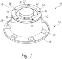
- a hub cap 10 is shown in figure 1 .
- the hub cap 10 as shown is a hub cap that is currently available from Stemco Products, Inc.
- the hub cap 10 as shown has a generally cylindrical body 12 with an inboard side 14 and an outboard side 16.
- the inboard side 14 has a flanged surface 18 having a plurality of bolt holes 20 to allow the hub cap 10 to be bolted to the wheel end.
- the outboard side 16 has a sight glass 22 and an end ring 24.
- the end ring 24 has bores 26 that receive fasteners 28 to couple the end ring 24, sight glass 22, and seals 23 to the outboard side 16 of the hub cap 10.
- the fasteners may be rivets, screws, pins, or the like.
- the end ring 24 and sight glass 22 may be integral with the outboard side 16 of the hub cap 10, which would remove the need for the bores 26, fasteners 28, and seals.
- vent plug 32 is provided in the aperture 30.
- the vent plug 32 has a cover 34 that is coupled to a base 36. The junction of the cover 34 and base 36 is at an interface 38.
- the vent plug 32 is located at the geometric center of the hub cap 10. In other embodiments, the vent plug 32 may be located off-center. In still other embodiments, a plurality of vent plugs may be provided at symmetrical or asymmetrical locations.
- FIG. 2 shows a cross sectional view of the vent plug 32 in isolation.
- the vent plug has the cover 34 coupled to the base 36.
- the base 36 has an outer edge surface 39 and a boarder wall 40 that form a shelf or ledge.
- the outer edge surface 39 has a width W1.
- the boarder wall 40 has an outer diameter D1.
- the cover 34 has a concave dome 42 and a rim 44 at the outer edge 43 of the dome 42.
- the rim 44 has a width W2.
- the rim 44 has an inner diameter D2 slightly smaller than the outer diameter D 1 such that a frictional engagement is maintained between the boarder wall 40 and the rim 44 to hold the cover 34 to the base 36.
- the inner diameter D2 of the rim 44 may be slightly stretched to be greater than the outer diameter D1 when installed to form the interference fit.
- An interface 38 between the cover 34 and the base 36 is formed by the boarder wall 40, outer edge surface 39, and the rim 44. Notice, in certain aspects, the cover 34 and the base 36 may be a single unit. If formed as a monolithic or single unit, the interface 38 may be replaced with perforations or the like. While shown as a friction fit, the cover 34 and the base 36 could be coupled using other coupling techniques such as, for example, welding (sonic or heat), adhering, gluing, curing, or the like.
- the cover 34 and the base 36 define a chamber 46.
- the cover 34 has a plurality of ribs 48, defining concentric rings, that extend into the chamber 46 towards the base 36.
- the base 36 has a plurality of ribs 48, defining concentric rings, that extend into the chamber 46 towards the cover 34.
- the ribs 48 of the cover 34 and the ribs 48 of the base 36 are generally alternating and define a labyrinth path 50 between a central aperture 52 in the base 36 and the interface 38.
- the labyrinth path 50 provides a tortuous vent path that allows gas to travel relatively freely, but inhibits liquids from leaking through the path, which inhibits the lubrication from exiting to the atmosphere.
- the base 36 further includes radially outward spaced apart apertures 54. The spaced apart apertures 54 allow air to vent into the lubrication cavity of the wheel end to inhibit the creation of a vacuum as the bearings and lubrication cool during periods of non-use.
- a valve 56 resides in the central aperture 52.
- the valve 56 is an elastic member and typically formed of an elastomeric.
- the valve 56 is further described in US Patent No. 5,860,708, issued January 19, 1999 , which is owned by Stemco.
- the valve 56 is designed such that the vent is normally closed until the pressure in the wheel end increases due to operation (or other reasons). When pressure exceeds a set point, the valve opens to allow pressure to vent.
- the base 36 is coupled to the vent plug body 58.
- the vent plug body 58 extends in an inboard direction from the base 36 forming a generally cylindrical, hollow cavity 60.
- the vent plug body 58 defines an inner diameter D3 although the vent plug body 58 may be cylindrical or frustoconical as shown.
- the outer surface 62 of the vent plug body 58 forms one or more annular glands 64, of which two annular glands 64 are shown. Seals 66, such as o-rings, form a seal between the vent plug 32 and the hub cap 10, more specifically, the sight glass 22.
- the annular glands 64 are generally formed with a portion of the vent plug body 58 forming the base of the annular gland 64 and one or more radially extending, annular ribs 68 forming walls of the annular gland 64.
- a shield 70 is coupled to the inboard side 72 of the vent plug body 58, which is distal to the base 36.
- the shield 70 as shown in figure 2 , has a radially extending disc body 74 and an axially extending connector ring 76 with a radially extending annular connecting surface 78.
- the disc body 74 has a shape to cooperatively work with the shape of the vent plug body 59.
- the radially extending annular connecting surface 78 has one or more bores 80.
- the radially extending disc body 74 has a diameter D4 slightly less than the corresponding diameter D3 of the vent plug body 58.
- Figure 3 shows a perspective view of the vent shield 70.
- the disc body 74 and the connector ring 76 are generally solid to inhibit lubricant from traversing from the lubrication cavity of the wheel end assembly to the cavity 60 of the vent plug 32.
- the connector ring 76 may have cutouts 77 to facilitate a gas vent path.
- the inboard side 72 of the vent plug body 58 provides connector protrusions 82.
- the connector protrusions 82 have an axially extending leg 84 and a radially extending ledge 86.
- the connector protrusions 82 align with the bores 80 in connecting surface 78.
- the terminal end 88 of the connector protrusions 82 may be tapered or chamfered to facilitate inserting the connector protrusions 82 into the bores 80.
- the elastic connector protrusion 82 moves the ledge 86 to engage the underside 90 of the connecting surface 78 forming a snap fit connection in this exemplary embodiment.
- connection between the shield 70 and the vent plug body 58 may be formed by alternative means, such as, for example, a friction fitting, adhesive, glues, welds, or the like.
- the shield may be molded with the vent plug body to form a monolithic piece.
- the shield 70 connection to the vent plug body 58 provides a leak path for gas (air) from the inboard wheel end to the vent plug body 58, and eventually to atmosphere through interface 38.
- FIG 4 shows an alternative version of the shield 70'.
- Shield 70' has a radially extending disc portion 74' and a radially extending annular connector surface 78' extending from an edge 73' of the disc portion 74'.
- the connector surface 78' may include bores 80' to receive the connector protrusions 82.
- the shield 70' includes vent channels 92' to facilitate air flow. The vent channels 92' may be incorporated into other shields described herein.
- FIG. 5 shows alternative vent plugs 94, 96, 98, and 100 with a shield 102, 104, 106, and 108.
- vent plugs 94, 96, and 98 provide a valve 56 but as shown by vent plug 100, a valve 56 is not a necessary component of the vent plug.
- the shields 70, 70', 102, 104, 106, and 108 inhibit the flow of lubricant into the vent plug body 58.
- the shield 102 includes an axially extending central member 110 that engages with the valve 56.
- Figure 7 shows a vent plug 120 with a shield 122 and a vent plug 124 with a shield 126. Placement of the shield 122 inside the vent plug body is shown towards the middle or outboard end 128 of the vent plug 120. The specific placement of the shield 122 may vary depending on the characteristics and/or material of the vent plug 120. Placement of shield 126 in vent plug 124 is toward the inboard end 130. In other words, the placement of the various shields described herein may be optimized for the particular construction of the vent plug.
- FIG 8 shows a detail of means for connecting the vent plug body to the shield.
- a portion of a vent plug body 132 is shown.
- the vent plug body 132 terminates, at the inboard side 134, with a shoulder 136.
- the shoulder 136 is formed by a radially extending annular surface 138 and an axially extending annular rim 140.
- the shield 142 has a radially extending annular ledge 144 that mates with the shoulder 136 and forms a junction 139.
- the shield 142 is coupled, in this exemplary embodiment, to the vent plug body 132 by a weld at points along junction 138.
- FIG 9 provides an alternative construction of a vent plug 200 with a shield 202.
- the vent plug 200 includes a cover 204 and a base 206.
- the cover 204 and base 206 would have annular concentric rings as described above, but not shown here, to provide a labyrinth seal.
- the vent plug 200 includes a valve 208, which is similar to the valve 56 described above.
- the vent plug 200 further includes an annular vent plug body 210 extending in an inboard direction from the base 206.
- the vent plug body 210 includes one or more annular glands 212, which are formed in part by an outer surface 214 of the vent plug body 210 and radially extending, annular rib 216.
- the shield 202 traverses the space 218 defined by the vent plug body 210.
- the shield 202 has perforations 220 that provide a vent path from the wheel end lubrication cavity to the space 218. While the shield 202 may be a disc that traverses the space 218, the exemplary shield 202 shown provides a central member 222 extending in an axial, outboard direction.
- the central member 222 is shown as a cylindrical member with a distal protrusion 224 that is sized to fit within a bore 226 of the valve 208.
- the central member 222 and protrusion 224 fitting within the bore 226 of the valve 208 provides for support among other things from the shield 202.
- vent plugs with shields generally provide a liquid barrier and a gas vent path.
- Figure 10 shows an exemplary vent path A for a vent plug 32 having a shield 70.
- Figure 11 shows an exemplary vent path B for a vent plug 32 having a shield 70'.
- a stated range of 1 to 10 should be considered to include and provide support for claims that recite any and all subranges or individual values that are between and/or inclusive of the minimum value of 1 and the maximum value of 10; that is, all subranges beginning with a minimum value of 1 or more and ending with a maximum value of 10 or less (e.g., 5.5 to 10, 2.34 to 3.56, and so forth) or any values from 1 to 10 (e.g., 3, 5.8, 9.9994, and so forth).
Landscapes
- Engineering & Computer Science (AREA)
- Mechanical Engineering (AREA)
- General Details Of Gearings (AREA)
- Pressure Vessels And Lids Thereof (AREA)
Claims (11)
- Entlüftungsstopfen (32) für eine Nabenabdeckung (10), umfassend:eine Abdeckung (34);eine Basis (36), die mit der Abdeckung gekoppelt ist und eine Schnittstelle (38) definiert, wobei die Basis innenliegend zu Abdeckung ist;eine Kammer (46) zwischen der Abdeckung und der Basis und durch diese definiert;einen ringförmigen Entlüftungsstopfenkörper (58), der mit der Basis gekoppelt ist und sich von der Basis aus in eine innenliegende Richtung erstreckt, wobei die Basis und der ringförmige Entlüftungsstopfenkörper einen Hohlraum (60) definieren;eine Abschirmung (70, 70'), die mit der innenliegenden Seite des Entlüftungsstopfens und innenliegend zu der Basis gekoppelt ist, wobei die Abschirmung im Allgemeinen den durch den ringförmigen Entlüftungsstopfenkörper definierten Hohlraum durchquert, wobeiein Entlüftungsweg (A, B) dazu konfiguriert ist, einen Schmierhohlraum einer Radendbaugruppe in Fluidverbindung mit dem Hohlraum zu platzieren, der das Austreten von Flüssigkeit zwischen der Radendbaugruppe und dem Hohlraum des Entlüftungsstopfens verhindert.
- Entlüftungsstopfen nach Anspruch 1, wobei die Abschirmung einen sich radial erstreckenden Scheibenkörper (74) und einen sich axial erstreckenden Verbinderring (76) umfasst.
- Entlüftungsstopfen nach Anspruch 2, wobei der Entlüftungsweg eine Bohrung (80) umfasst, die sich in dem sich radial erstreckenden Scheibenkörper befindet oder sich in einer ringförmigen Verbindungsoberfläche auf dem sich axial erstreckenden Verbinderring befindet.
- Entlüftungsstopfen nach Anspruch 3, wobei der Entlüftungsstopfenkörper wenigstens einen Verbindervorsprung (82) umfasst, der geformt ist, um eine Verbindung mit der wenigstens einen Bohrung auszubilden.
- Entlüftungsstopfen nach Anspruch 4, wobei der wenigstens eine Verbindervorsprung einen elastischen Schenkel (84) und eine sich radial erstreckende Leiste (86) umfasst, um in die Unterseite der ringförmigen Verbindungsoberfläche einzugreifen.
- Entlüftungsstopfen nach einem der vorhergehenden Ansprüche, wobei die Abschirmung (70) wenigstens eines von monolithisch mit dem Entlüftungsstopfenkörper oder an den Entlüftungsstopfenkörper geschweißt ist.
- Entlüftungsstopfen nach Anspruch 2, wobei der sich radial erstreckende Scheibenkörper Entlüftungskanäle (92) umfasst.
- Entlüftungsstopfen nach Anspruch 1, umfassend:den Entlüftungsstopfenkörper (58) mit einer außenliegenden Seite proximal zu der Basis und einer innenliegenden Seite distal zu der Basis;die Abschirmung (70), die wenigstens eine sich radial erstreckende Scheibe umfasst, die mit dem Entlüftungsstopfenkörper gekoppelt ist und innenliegend zu der Basis ist; undwobei der Entlüftungsweg (A, B) dazu konfiguriert ist, zu ermöglichen, dass Gas aus dem Schmierhohlraum in den Hohlraum und durch die Basis in die Atmosphäre entlüftet, und dazu konfiguriert ist, das Austreten von Flüssigkeit zwischen dem Schmierhohlraum und dem Hohlraum des Entlüftungsstopfens zu verhindern.
- Entlüftungsstopfen nach Anspruch 8, umfassend ein Ventil (56), das in wenigstens einer Öffnung der Basis gehalten wird und derart konfiguriert ist, dass das Ventil in Fluidverbindung mit dem Hohlraum steht.
- Entlüftungsstopfen nach Anspruch 9, wobei das Ventil (56) dazu konfiguriert ist, sich zu öffnen, wenn der Hohlraum einen Druckschwellenwert überschreitet, um den Hohlraum in gasförmige Fluidkommunikation mit der Atmosphäre zu platzieren.
- Entlüftungsstopfen nach Anspruch 8, wobei die Abdeckung eine Mehrzahl von Abdeckungsrippen umfasst, die sich von der Abdeckung zu der Basis erstrecken, und die Basis eine Mehrzahl von Basisrippen definiert, die sich von der Basis zu der Abdeckung erstrecken, wobei die Mehrzahl von Abdeckungsrippen gegenüber der Mehrzahl von Basisrippen versetzt ist, sodass der Entlüftungsweg teilweise durch einen Labyrinthweg (50) durch die Mehrzahl von Abdeckungsrippen und die Mehrzahl von Basisrippen in der Kammer definiert ist.
Applications Claiming Priority (2)
| Application Number | Priority Date | Filing Date | Title |
|---|---|---|---|
| US201862629266P | 2018-02-12 | 2018-02-12 | |
| PCT/US2019/016475 WO2019156920A1 (en) | 2018-02-12 | 2019-02-04 | Hub cap vent shield |
Publications (3)
| Publication Number | Publication Date |
|---|---|
| EP3752373A1 EP3752373A1 (de) | 2020-12-23 |
| EP3752373A4 EP3752373A4 (de) | 2021-11-17 |
| EP3752373B1 true EP3752373B1 (de) | 2024-11-13 |
Family
ID=67548053
Family Applications (1)
| Application Number | Title | Priority Date | Filing Date |
|---|---|---|---|
| EP19751202.3A Active EP3752373B1 (de) | 2018-02-12 | 2019-02-04 | Entlüftungsstopfen für eine nabenkappe |
Country Status (6)
| Country | Link |
|---|---|
| US (2) | US11021009B2 (de) |
| EP (1) | EP3752373B1 (de) |
| CN (1) | CN112074420B (de) |
| CA (1) | CA3090471A1 (de) |
| MX (1) | MX2020008423A (de) |
| WO (1) | WO2019156920A1 (de) |
Families Citing this family (3)
| Publication number | Priority date | Publication date | Assignee | Title |
|---|---|---|---|---|
| CA3090471A1 (en) | 2018-02-12 | 2019-08-15 | Stemco Products, Inc. | Hub cap vent shield |
| US12403722B2 (en) | 2022-08-24 | 2025-09-02 | Amsted Rail Company, Inc. | Hubcap |
| US20250237313A1 (en) * | 2024-01-24 | 2025-07-24 | Consolidated Metco, Inc. | Air vent for a wheel hub assembly |
Family Cites Families (23)
| Publication number | Priority date | Publication date | Assignee | Title |
|---|---|---|---|---|
| US3316022A (en) * | 1965-10-15 | 1967-04-25 | Chicago Rawhide Mfg Co | Hub cap assembly |
| SU1696322A1 (ru) | 1989-02-06 | 1991-12-07 | Egin Nikolaj L | Колесо транспортного средства |
| US5505525A (en) | 1994-01-10 | 1996-04-09 | Skf Usa Inc. | Hubcap and method of manufacturing the same |
| US5785390A (en) * | 1995-01-31 | 1998-07-28 | Stemco Inc. | Vented hubcap |
| US5752746A (en) * | 1995-12-15 | 1998-05-19 | Stemco Inc | Hubcap with vented closure |
| US5870708A (en) | 1996-10-10 | 1999-02-09 | Walter S. Stewart | Method of and apparatus for scanning for and replacing words on video cassettes |
| US5860708A (en) * | 1997-07-11 | 1999-01-19 | Stemco Inc | Contaminant excluding hubcap vent plug |
| US20040160115A1 (en) * | 2003-02-13 | 2004-08-19 | Allsop M. Sid | Hub cap having an air valve for bearing cavity pressurization |
| US6783191B1 (en) * | 2003-03-11 | 2004-08-31 | Dana Corporation | Axle hubcap vent |
| US7100995B2 (en) | 2003-09-08 | 2006-09-05 | Gls Wheels, L.L.C. | Wheel spinner assembly |
| US7156890B1 (en) * | 2004-03-01 | 2007-01-02 | Di-Pro, Inc. | Hubcap filter |
| FR2915711B1 (fr) | 2007-05-03 | 2009-11-27 | Renault Sas | Agencement de train roulant pour un vehicule automobile |
| JP5756339B2 (ja) | 2011-05-23 | 2015-07-29 | 日信工業株式会社 | 電気部品組立体及び車両用ブレーキ液圧制御装置 |
| DE102011117088A1 (de) | 2011-10-27 | 2013-05-02 | Volkswagen Aktiengesellschaft | Radoberflächenelement |
| US9221308B2 (en) * | 2012-02-06 | 2015-12-29 | Stemco Lp | Central tire inflation system rotary air union |
| DE102013105834B4 (de) * | 2013-06-06 | 2025-11-27 | Dr. Ing. H.C. F. Porsche Aktiengesellschaft | Radnabendeckelanordnung sowie Radnabe für ein Kraftfahrzeug |
| DE102013107394A1 (de) | 2013-07-12 | 2015-01-15 | Thyssenkrupp Steel Europe Ag | Fahrzeugrad und Verfahren zur Herstellung eines Fahrzeugrades |
| CN203472406U (zh) | 2013-09-03 | 2014-03-12 | 李铁葵 | 发光轮毂盖 |
| US9421819B2 (en) * | 2014-11-24 | 2016-08-23 | Consolidated Metco, Inc. | Vehicle wheel hubcap with vent |
| DE112016005740T5 (de) * | 2015-12-15 | 2018-10-04 | Dana Heavy Vehicle Systems Group, Llc | Nabenkappenanordnung mit Sichtglas |
| CN205553763U (zh) | 2016-03-30 | 2016-09-07 | 江苏车谷新材料有限公司 | 一种可以保护轮胎的轮毂 |
| US10589038B2 (en) | 2016-04-27 | 2020-03-17 | Medtronic Minimed, Inc. | Set connector systems for venting a fluid reservoir |
| CA3090471A1 (en) * | 2018-02-12 | 2019-08-15 | Stemco Products, Inc. | Hub cap vent shield |
-
2019
- 2019-02-04 CA CA3090471A patent/CA3090471A1/en active Pending
- 2019-02-04 CN CN201980025384.3A patent/CN112074420B/zh active Active
- 2019-02-04 US US16/606,719 patent/US11021009B2/en active Active
- 2019-02-04 WO PCT/US2019/016475 patent/WO2019156920A1/en not_active Ceased
- 2019-02-04 EP EP19751202.3A patent/EP3752373B1/de active Active
- 2019-02-04 MX MX2020008423A patent/MX2020008423A/es unknown
-
2021
- 2021-05-27 US US17/332,582 patent/US11667150B2/en active Active
Also Published As
| Publication number | Publication date |
|---|---|
| MX2020008423A (es) | 2021-03-02 |
| EP3752373A1 (de) | 2020-12-23 |
| CA3090471A1 (en) | 2019-08-15 |
| US11667150B2 (en) | 2023-06-06 |
| BR112020015891A2 (pt) | 2021-02-02 |
| WO2019156920A1 (en) | 2019-08-15 |
| EP3752373A4 (de) | 2021-11-17 |
| US20200369076A1 (en) | 2020-11-26 |
| CN112074420A (zh) | 2020-12-11 |
| US11021009B2 (en) | 2021-06-01 |
| CN112074420B (zh) | 2022-06-07 |
| US20210354506A1 (en) | 2021-11-18 |
Similar Documents
| Publication | Publication Date | Title |
|---|---|---|
| US11667150B2 (en) | Hub cap vent shield | |
| US4428630A (en) | Sealed bearing and self-venting seal therefor | |
| US5538330A (en) | Axle vent | |
| US6637943B2 (en) | Hub assembly for automotive vehicles | |
| EP0905394B1 (de) | Betriebsfertiges Lager mit Halter | |
| US5860708A (en) | Contaminant excluding hubcap vent plug | |
| EP0228847B1 (de) | Dichtung | |
| US4226426A (en) | Semi-unitized shaft seal | |
| US9308776B2 (en) | Vent plug for a hubcap and method of manufacturing the same | |
| CN102267336A (zh) | 轮毂组件 | |
| US8490986B1 (en) | Steering knuckle assembly having a kingpin | |
| US9421819B2 (en) | Vehicle wheel hubcap with vent | |
| US12325267B2 (en) | Wheel comprising an internal inflation channel, landing gear and an aircraft comprising such a wheel | |
| EP2843254A2 (de) | Lagereinheit | |
| US10207550B2 (en) | Rotary joint assembly | |
| US11433704B2 (en) | Axle assembly and the tire inflation system made therewith | |
| US6095925A (en) | Seal assembly and seal guard for a universal joint | |
| US6155573A (en) | Removable and replaceable hub seal | |
| US20200079144A1 (en) | Shielded vent plug for wheel end hubcaps | |
| US4241957A (en) | Wheel bearing slinger ring | |
| US4269459A (en) | Wheel bearing slinger ring | |
| US12337612B2 (en) | Seal mechanism for wheel assemblies | |
| BR112020015891B1 (pt) | Bujão de ventilação para uma tampa de cubo | |
| US20260117824A1 (en) | Low-friction sealing device and associated rolling bearing | |
| JP2016041949A (ja) | 車輪支持用転がり軸受ユニット |
Legal Events
| Date | Code | Title | Description |
|---|---|---|---|
| STAA | Information on the status of an ep patent application or granted ep patent |
Free format text: STATUS: THE INTERNATIONAL PUBLICATION HAS BEEN MADE |
|
| PUAI | Public reference made under article 153(3) epc to a published international application that has entered the european phase |
Free format text: ORIGINAL CODE: 0009012 |
|
| STAA | Information on the status of an ep patent application or granted ep patent |
Free format text: STATUS: REQUEST FOR EXAMINATION WAS MADE |
|
| 17P | Request for examination filed |
Effective date: 20200810 |
|
| AK | Designated contracting states |
Kind code of ref document: A1 Designated state(s): AL AT BE BG CH CY CZ DE DK EE ES FI FR GB GR HR HU IE IS IT LI LT LU LV MC MK MT NL NO PL PT RO RS SE SI SK SM TR |
|
| AX | Request for extension of the european patent |
Extension state: BA ME |
|
| DAV | Request for validation of the european patent (deleted) | ||
| DAX | Request for extension of the european patent (deleted) | ||
| A4 | Supplementary search report drawn up and despatched |
Effective date: 20211018 |
|
| RIC1 | Information provided on ipc code assigned before grant |
Ipc: B60B 7/00 20060101ALI20211012BHEP Ipc: B60B 7/04 20060101AFI20211012BHEP |
|
| STAA | Information on the status of an ep patent application or granted ep patent |
Free format text: STATUS: EXAMINATION IS IN PROGRESS |
|
| 17Q | First examination report despatched |
Effective date: 20230524 |
|
| GRAP | Despatch of communication of intention to grant a patent |
Free format text: ORIGINAL CODE: EPIDOSNIGR1 |
|
| STAA | Information on the status of an ep patent application or granted ep patent |
Free format text: STATUS: GRANT OF PATENT IS INTENDED |
|
| INTG | Intention to grant announced |
Effective date: 20240607 |
|
| GRAS | Grant fee paid |
Free format text: ORIGINAL CODE: EPIDOSNIGR3 |
|
| GRAA | (expected) grant |
Free format text: ORIGINAL CODE: 0009210 |
|
| STAA | Information on the status of an ep patent application or granted ep patent |
Free format text: STATUS: THE PATENT HAS BEEN GRANTED |
|
| P01 | Opt-out of the competence of the unified patent court (upc) registered |
Free format text: CASE NUMBER: APP_51409/2024 Effective date: 20240911 |
|
| AK | Designated contracting states |
Kind code of ref document: B1 Designated state(s): AL AT BE BG CH CY CZ DE DK EE ES FI FR GB GR HR HU IE IS IT LI LT LU LV MC MK MT NL NO PL PT RO RS SE SI SK SM TR |
|
| REG | Reference to a national code |
Ref country code: GB Ref legal event code: FG4D |
|
| REG | Reference to a national code |
Ref country code: CH Ref legal event code: EP |
|
| REG | Reference to a national code |
Ref country code: DE Ref legal event code: R096 Ref document number: 602019061941 Country of ref document: DE |
|
| REG | Reference to a national code |
Ref country code: IE Ref legal event code: FG4D |
|
| REG | Reference to a national code |
Ref country code: LT Ref legal event code: MG9D |
|
| REG | Reference to a national code |
Ref country code: NL Ref legal event code: MP Effective date: 20241113 |
|
| PG25 | Lapsed in a contracting state [announced via postgrant information from national office to epo] |
Ref country code: IS Free format text: LAPSE BECAUSE OF FAILURE TO SUBMIT A TRANSLATION OF THE DESCRIPTION OR TO PAY THE FEE WITHIN THE PRESCRIBED TIME-LIMIT Effective date: 20250313 Ref country code: PT Free format text: LAPSE BECAUSE OF FAILURE TO SUBMIT A TRANSLATION OF THE DESCRIPTION OR TO PAY THE FEE WITHIN THE PRESCRIBED TIME-LIMIT Effective date: 20250313 Ref country code: HR Free format text: LAPSE BECAUSE OF FAILURE TO SUBMIT A TRANSLATION OF THE DESCRIPTION OR TO PAY THE FEE WITHIN THE PRESCRIBED TIME-LIMIT Effective date: 20241113 |
|
| PG25 | Lapsed in a contracting state [announced via postgrant information from national office to epo] |
Ref country code: NL Free format text: LAPSE BECAUSE OF FAILURE TO SUBMIT A TRANSLATION OF THE DESCRIPTION OR TO PAY THE FEE WITHIN THE PRESCRIBED TIME-LIMIT Effective date: 20241113 Ref country code: FI Free format text: LAPSE BECAUSE OF FAILURE TO SUBMIT A TRANSLATION OF THE DESCRIPTION OR TO PAY THE FEE WITHIN THE PRESCRIBED TIME-LIMIT Effective date: 20241113 |
|
| REG | Reference to a national code |
Ref country code: AT Ref legal event code: MK05 Ref document number: 1741419 Country of ref document: AT Kind code of ref document: T Effective date: 20241113 |
|
| PG25 | Lapsed in a contracting state [announced via postgrant information from national office to epo] |
Ref country code: BG Free format text: LAPSE BECAUSE OF FAILURE TO SUBMIT A TRANSLATION OF THE DESCRIPTION OR TO PAY THE FEE WITHIN THE PRESCRIBED TIME-LIMIT Effective date: 20241113 |
|
| PG25 | Lapsed in a contracting state [announced via postgrant information from national office to epo] |
Ref country code: ES Free format text: LAPSE BECAUSE OF FAILURE TO SUBMIT A TRANSLATION OF THE DESCRIPTION OR TO PAY THE FEE WITHIN THE PRESCRIBED TIME-LIMIT Effective date: 20241113 |
|
| PG25 | Lapsed in a contracting state [announced via postgrant information from national office to epo] |
Ref country code: NO Free format text: LAPSE BECAUSE OF FAILURE TO SUBMIT A TRANSLATION OF THE DESCRIPTION OR TO PAY THE FEE WITHIN THE PRESCRIBED TIME-LIMIT Effective date: 20250213 |
|
| PG25 | Lapsed in a contracting state [announced via postgrant information from national office to epo] |
Ref country code: LV Free format text: LAPSE BECAUSE OF FAILURE TO SUBMIT A TRANSLATION OF THE DESCRIPTION OR TO PAY THE FEE WITHIN THE PRESCRIBED TIME-LIMIT Effective date: 20241113 Ref country code: GR Free format text: LAPSE BECAUSE OF FAILURE TO SUBMIT A TRANSLATION OF THE DESCRIPTION OR TO PAY THE FEE WITHIN THE PRESCRIBED TIME-LIMIT Effective date: 20250214 Ref country code: AT Free format text: LAPSE BECAUSE OF FAILURE TO SUBMIT A TRANSLATION OF THE DESCRIPTION OR TO PAY THE FEE WITHIN THE PRESCRIBED TIME-LIMIT Effective date: 20241113 |
|
| PG25 | Lapsed in a contracting state [announced via postgrant information from national office to epo] |
Ref country code: PL Free format text: LAPSE BECAUSE OF FAILURE TO SUBMIT A TRANSLATION OF THE DESCRIPTION OR TO PAY THE FEE WITHIN THE PRESCRIBED TIME-LIMIT Effective date: 20241113 |
|
| PG25 | Lapsed in a contracting state [announced via postgrant information from national office to epo] |
Ref country code: RS Free format text: LAPSE BECAUSE OF FAILURE TO SUBMIT A TRANSLATION OF THE DESCRIPTION OR TO PAY THE FEE WITHIN THE PRESCRIBED TIME-LIMIT Effective date: 20250213 |
|
| PG25 | Lapsed in a contracting state [announced via postgrant information from national office to epo] |
Ref country code: SM Free format text: LAPSE BECAUSE OF FAILURE TO SUBMIT A TRANSLATION OF THE DESCRIPTION OR TO PAY THE FEE WITHIN THE PRESCRIBED TIME-LIMIT Effective date: 20241113 |
|
| PG25 | Lapsed in a contracting state [announced via postgrant information from national office to epo] |
Ref country code: DK Free format text: LAPSE BECAUSE OF FAILURE TO SUBMIT A TRANSLATION OF THE DESCRIPTION OR TO PAY THE FEE WITHIN THE PRESCRIBED TIME-LIMIT Effective date: 20241113 |
|
| PG25 | Lapsed in a contracting state [announced via postgrant information from national office to epo] |
Ref country code: EE Free format text: LAPSE BECAUSE OF FAILURE TO SUBMIT A TRANSLATION OF THE DESCRIPTION OR TO PAY THE FEE WITHIN THE PRESCRIBED TIME-LIMIT Effective date: 20241113 |
|
| PG25 | Lapsed in a contracting state [announced via postgrant information from national office to epo] |
Ref country code: RO Free format text: LAPSE BECAUSE OF FAILURE TO SUBMIT A TRANSLATION OF THE DESCRIPTION OR TO PAY THE FEE WITHIN THE PRESCRIBED TIME-LIMIT Effective date: 20241113 |
|
| PG25 | Lapsed in a contracting state [announced via postgrant information from national office to epo] |
Ref country code: SK Free format text: LAPSE BECAUSE OF FAILURE TO SUBMIT A TRANSLATION OF THE DESCRIPTION OR TO PAY THE FEE WITHIN THE PRESCRIBED TIME-LIMIT Effective date: 20241113 |
|
| PG25 | Lapsed in a contracting state [announced via postgrant information from national office to epo] |
Ref country code: CZ Free format text: LAPSE BECAUSE OF FAILURE TO SUBMIT A TRANSLATION OF THE DESCRIPTION OR TO PAY THE FEE WITHIN THE PRESCRIBED TIME-LIMIT Effective date: 20241113 |
|
| PG25 | Lapsed in a contracting state [announced via postgrant information from national office to epo] |
Ref country code: IT Free format text: LAPSE BECAUSE OF FAILURE TO SUBMIT A TRANSLATION OF THE DESCRIPTION OR TO PAY THE FEE WITHIN THE PRESCRIBED TIME-LIMIT Effective date: 20241113 |
|
| REG | Reference to a national code |
Ref country code: DE Ref legal event code: R097 Ref document number: 602019061941 Country of ref document: DE |
|
| PG25 | Lapsed in a contracting state [announced via postgrant information from national office to epo] |
Ref country code: SE Free format text: LAPSE BECAUSE OF FAILURE TO SUBMIT A TRANSLATION OF THE DESCRIPTION OR TO PAY THE FEE WITHIN THE PRESCRIBED TIME-LIMIT Effective date: 20241113 |
|
| PG25 | Lapsed in a contracting state [announced via postgrant information from national office to epo] |
Ref country code: MC Free format text: LAPSE BECAUSE OF FAILURE TO SUBMIT A TRANSLATION OF THE DESCRIPTION OR TO PAY THE FEE WITHIN THE PRESCRIBED TIME-LIMIT Effective date: 20241113 |
|
| PLBE | No opposition filed within time limit |
Free format text: ORIGINAL CODE: 0009261 |
|
| STAA | Information on the status of an ep patent application or granted ep patent |
Free format text: STATUS: NO OPPOSITION FILED WITHIN TIME LIMIT |
|
| REG | Reference to a national code |
Ref country code: CH Ref legal event code: PL |
|
| PG25 | Lapsed in a contracting state [announced via postgrant information from national office to epo] |
Ref country code: LU Free format text: LAPSE BECAUSE OF NON-PAYMENT OF DUE FEES Effective date: 20250204 |
|
| PG25 | Lapsed in a contracting state [announced via postgrant information from national office to epo] |
Ref country code: CH Free format text: LAPSE BECAUSE OF NON-PAYMENT OF DUE FEES Effective date: 20250228 |
|
| 26N | No opposition filed |
Effective date: 20250814 |
|
| REG | Reference to a national code |
Ref country code: BE Ref legal event code: MM Effective date: 20250228 |
|
| PG25 | Lapsed in a contracting state [announced via postgrant information from national office to epo] |
Ref country code: BE Free format text: LAPSE BECAUSE OF NON-PAYMENT OF DUE FEES Effective date: 20250228 |
|
| PG25 | Lapsed in a contracting state [announced via postgrant information from national office to epo] |
Ref country code: IE Free format text: LAPSE BECAUSE OF NON-PAYMENT OF DUE FEES Effective date: 20250204 |
|
| PGFP | Annual fee paid to national office [announced via postgrant information from national office to epo] |
Ref country code: GB Payment date: 20260220 Year of fee payment: 8 |
|
| PGFP | Annual fee paid to national office [announced via postgrant information from national office to epo] |
Ref country code: DE Payment date: 20260218 Year of fee payment: 8 |
|
| PGFP | Annual fee paid to national office [announced via postgrant information from national office to epo] |
Ref country code: FR Payment date: 20260218 Year of fee payment: 8 |