EP3752270B1 - Filterpatrone mit befehlsvorrichtung - Google Patents
Filterpatrone mit befehlsvorrichtung Download PDFInfo
- Publication number
- EP3752270B1 EP3752270B1 EP19707496.6A EP19707496A EP3752270B1 EP 3752270 B1 EP3752270 B1 EP 3752270B1 EP 19707496 A EP19707496 A EP 19707496A EP 3752270 B1 EP3752270 B1 EP 3752270B1
- Authority
- EP
- European Patent Office
- Prior art keywords
- filter
- filter cartridge
- engagement
- cartridge
- tooth element
- Prior art date
- Legal status (The legal status is an assumption and is not a legal conclusion. Google has not performed a legal analysis and makes no representation as to the accuracy of the status listed.)
- Active
Links
Images








Classifications
-
- B—PERFORMING OPERATIONS; TRANSPORTING
- B01—PHYSICAL OR CHEMICAL PROCESSES OR APPARATUS IN GENERAL
- B01D—SEPARATION
- B01D29/00—Filters with filtering elements stationary during filtration, e.g. pressure or suction filters, not covered by groups B01D24/00 - B01D27/00; Filtering elements therefor
- B01D29/96—Filters with filtering elements stationary during filtration, e.g. pressure or suction filters, not covered by groups B01D24/00 - B01D27/00; Filtering elements therefor in which the filtering elements are moved between filtering operations; Particular measures for removing or replacing the filtering elements; Transport systems for filters
-
- B—PERFORMING OPERATIONS; TRANSPORTING
- B01—PHYSICAL OR CHEMICAL PROCESSES OR APPARATUS IN GENERAL
- B01D—SEPARATION
- B01D35/00—Filtering devices having features not specifically covered by groups B01D24/00 - B01D33/00, or for applications not specifically covered by groups B01D24/00 - B01D33/00; Auxiliary devices for filtration; Filter housing constructions
- B01D35/30—Filter housing constructions
- B01D35/306—Filter mounting adapter
-
- B—PERFORMING OPERATIONS; TRANSPORTING
- B01—PHYSICAL OR CHEMICAL PROCESSES OR APPARATUS IN GENERAL
- B01D—SEPARATION
- B01D35/00—Filtering devices having features not specifically covered by groups B01D24/00 - B01D33/00, or for applications not specifically covered by groups B01D24/00 - B01D33/00; Auxiliary devices for filtration; Filter housing constructions
- B01D35/30—Filter housing constructions
-
- B—PERFORMING OPERATIONS; TRANSPORTING
- B01—PHYSICAL OR CHEMICAL PROCESSES OR APPARATUS IN GENERAL
- B01D—SEPARATION
- B01D29/00—Filters with filtering elements stationary during filtration, e.g. pressure or suction filters, not covered by groups B01D24/00 - B01D27/00; Filtering elements therefor
- B01D29/11—Filters with filtering elements stationary during filtration, e.g. pressure or suction filters, not covered by groups B01D24/00 - B01D27/00; Filtering elements therefor with bag, cage, hose, tube, sleeve or like filtering elements
- B01D29/13—Supported filter elements
- B01D29/15—Supported filter elements arranged for inward flow filtration
- B01D29/21—Supported filter elements arranged for inward flow filtration with corrugated, folded or wound sheets
-
- B—PERFORMING OPERATIONS; TRANSPORTING
- B01—PHYSICAL OR CHEMICAL PROCESSES OR APPARATUS IN GENERAL
- B01D—SEPARATION
- B01D2201/00—Details relating to filtering apparatus
- B01D2201/29—Filter cartridge constructions
- B01D2201/291—End caps
-
- B—PERFORMING OPERATIONS; TRANSPORTING
- B01—PHYSICAL OR CHEMICAL PROCESSES OR APPARATUS IN GENERAL
- B01D—SEPARATION
- B01D2201/00—Details relating to filtering apparatus
- B01D2201/29—Filter cartridge constructions
- B01D2201/291—End caps
- B01D2201/296—Other than having a circular shape
-
- B—PERFORMING OPERATIONS; TRANSPORTING
- B01—PHYSICAL OR CHEMICAL PROCESSES OR APPARATUS IN GENERAL
- B01D—SEPARATION
- B01D2201/00—Details relating to filtering apparatus
- B01D2201/30—Filter housing constructions
- B01D2201/301—Details of removable closures, lids, caps, filter heads
- B01D2201/302—Details of removable closures, lids, caps, filter heads having inlet or outlet ports
-
- B—PERFORMING OPERATIONS; TRANSPORTING
- B01—PHYSICAL OR CHEMICAL PROCESSES OR APPARATUS IN GENERAL
- B01D—SEPARATION
- B01D2201/00—Details relating to filtering apparatus
- B01D2201/30—Filter housing constructions
- B01D2201/301—Details of removable closures, lids, caps, filter heads
- B01D2201/305—Snap, latch or clip connecting means
-
- B—PERFORMING OPERATIONS; TRANSPORTING
- B01—PHYSICAL OR CHEMICAL PROCESSES OR APPARATUS IN GENERAL
- B01D—SEPARATION
- B01D2201/00—Details relating to filtering apparatus
- B01D2201/40—Special measures for connecting different parts of the filter
- B01D2201/4046—Means for avoiding false mounting of different parts
-
- B—PERFORMING OPERATIONS; TRANSPORTING
- B01—PHYSICAL OR CHEMICAL PROCESSES OR APPARATUS IN GENERAL
- B01D—SEPARATION
- B01D2201/00—Details relating to filtering apparatus
- B01D2201/40—Special measures for connecting different parts of the filter
- B01D2201/4076—Anti-rotational means
Definitions
- the present invention relates to a filter cartridge of a filter group of a fluid.
- the present invention also relates to the filter group of a fluid, the assembly method and disassembly method thereof.
- the present invention finds its preferred application in the automotive sector. Specifically, in fact, the context in which the present invention lies is that of filtration systems of a fluid with particular reference to fluids, liquids or gases needed for the operation of a motor vehicle.
- the filter group of a fluid and the components that comprise it as per the present invention find their application in the air circuits, oil circuits, fuel circuits and/or in the water (or aqueous solutions) circuits included in a vehicle.
- Such known filtration systems comprise one (or more) filter cartridges integrally connected to a base assembly fluidically connected to the respective fluid circulation system.
- the filter group and the base assembly have different geometries and physical characteristics.
- said filter cartridge needs to be replaceable according to the needs of the motor vehicle, for example to be replaceable in the case of necessary maintenance.
- the main problem of the known filtration systems is therefore that of making the engagement and disengagement operations of the filter cartridge and base assembly simple and intuitive. Along with this need, at the same time a blocking configuration is required in which the filter cartridge and base assembly are reciprocally joined, this blocking being guaranteed over time, avoiding the risk of unwanted detachment of the same.
- the purpose of the present invention is therefore to specifically provide a filter group of a fluid that ensures the safe blocking of the filter cartridge to its respective base assembly, but which also allows simple and intuitive engagement and disengagement operations.
- reference numeral 1 globally denotes a filter group of a fluid.
- reference numeral 10 denotes a filter cartridge, while a base assembly is indicated by reference numeral 100.
- the filter group of a fluid 1 extends mainly in a main axial direction, in particular along a main axis X-X.
- the filter group of a fluid 1 comprises the filter cartridge 10 (hereinafter extensively described) and the base assembly 100 (in turn, extensively described).
- the two components are thus arranged consecutively along said main axis X-X.
- the filter group of a fluid 1 also includes special engagement means 2 suitable for engaging and disengaging the filter cartridge 10 and the base assembly 100 along said main axis X-X.
- said means of engagement comprise first engagement members 20, or cartridge engagement members, comprised in the filter cartridge 10 and second engagement members 200, or base engagement members, comprised in the base assembly 100.
- first engagement members 20 and the second engagement members 200 are respectively specially configured to engage each other in a blocking configuration in which the filter cartridge 10 and the base assembly 100 are mutually axially blocked.
- first engagement members 20 and the second engagement members 200 are specially designed in such a way that in the blocking configuration, the first are housed in the second.
- first engagement members 20 and the second engagement members 200 are complementary to each other in such a way as to block the two components in the axial direction.
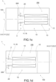
- Figures 1a, 1b , 1c, and 1d show schematic schemes of filtration systems of a fluid 1 according to the present invention, downstream and/or upstream of which the relative ducts of the respective filter group which the fluid circulation system which it is suitable to be part of are located on.
- these schemes are suitable for applying to any type of filter group of a fluid 1 regardless of the nature of said fluid.
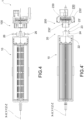
- Figures 2 to 4 instead, show a preferred embodiment of a filter group of a fluid 1 in which fuel, preferably of the diesel type, is filtered.
- the base assembly 100 is placed fluidically upstream of the filter cartridge 10.
- Figures 6 to 8 show a second preferred embodiment of a filter group of a fluid 1 in which fuel is filtered, preferably of the diesel type.
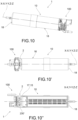
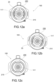
- Figures 10 to 12 show a third preferred embodiment of a filter group of a fluid 1 in which fuel is filtered, preferably of the diesel type.
- Figure 5 instead is a schematic diagram of a filter group of a fluid 1 according to an embodiment variant with respect to that of Figures 2 and 4 , not necessarily limited to the filtration of fuel, not necessarily having the base assembly 100 positioned upstream of the filter cartridge 10.
- Figure 9 is instead a schematic diagram of a filter group of a fluid 1 according to an embodiment variant with respect to that of Figures 6 to 8 , not necessarily limited to the filtration of fuel, not necessarily having the base assembly 100 positioned upstream of the filter cartridge 10.
- Figure 13 instead is a schematic diagram of a filter group of a fluid 1 according to an embodiment variant with respect to that of Figures 10 to 12 , not necessarily limited to the filtration of fuel, not necessarily having the base assembly 100 positioned upstream of the filter cartridge 10.
- the reciprocal engagement between the filter cartridge 10 and base assembly 100 takes place in the axial direction along the main axis X-X by means of a reciprocal axial insertion.
- the reciprocal engagement between the filter cartridge 10 and base assembly 100 takes place in a rotary direction along the main axis X-X.
- the filter cartridge 10 extends along a cartridge axis Z-Z.
- the cartridge axis Z-Z coincides with the main axis X-X.
- the filter cartridge 10 comprises at an axial end an engagement plane 15 on which said first engagement members 20 are made.
- the first engagement members 20 extend in height starting from the engagement plane 15.
- the filter cartridge 10 comprises a filter medium 13, preferably of the hollow cylindrical type which is traversable by the fluid radially, extending along the cartridge axis Z-Z.
- the filter cartridge 10 comprises a filter medium 13, preferably of the hollow type which is traversable by the fluid radially, extending along the cartridge axis Z-Z.
- the filter medium 13 has an axial extension along the Z-Z axis and is crossed by working fluid in a substantially axial direction, parallel to the Z-Z axis.
- the present invention is independent of the direction in which the fluid passes through the filter medium 13.
- the filter cartridge 10 comprises a first filter plate 11 and a second filter plate 12 placed at the axial ends of the filter medium 13, for example welded at its ends.
- one out of the first filter plate 11 or the second filter plate 12 correspond with the engagement plane 15 presenting on it said first engagement members 20.
- the filter cartridge 10 comprises a cartridge body 16, preferably of a cylindrical shape, having its extension along said cartridge axis Z-Z between a first body plate 17 and a second body plate 18.
- the filter medium 13 on which the first filter plate 11 and the second filter plate 12 are placed, which is preferably suitable to internally engage the cartridge body 16 to keep the filter medium 13 in a predefined axial position is housed inside said cartridge body 16.
- said filtration operations are performed inside said cartridge body 16.
- one out of the first body plate 17 or the second body plate 18 corresponds with the engagement plane 15, presenting on it said first engagement members 20.
- the first engagement members 20 comprise at least two tooth elements 21 diametrically opposite to the cartridge axis Z-Z.
- the tooth elements 21 lie in opposite halves defined by an imaginary plane on which the cartridge axis Z-Z extends.
- the tooth elements 21 are reciprocally angularly spaced, preferably, but not necessarily, angularly equidistant.
- the tooth elements are arranged in an asymmetrical manner.
- the tooth elements are arranged in a symmetrical manner. According to the above description, the tooth elements 21 are radially spaced from the cartridge axis Z-Z.
- Each tooth element 21 extends in height from the engagement plane 15 extending totally or partially on an imaginary surface parallel to the cartridge axis Z-Z, having a substantially T shape or substantially L-shape.
- the tooth element 21 lies at least in its portion extending axially, on a single surface extending parallel to the cartridge axis Z-Z.
- said surface is planar (therefore the two distally opposite tooth elements 21 extend on respective imaginary surfaces parallel to each other).
- said surface is arched, for example circumferential (i.e., the two distally opposite tooth elements 21 extend on a respective imaginary surface extending concentrically to the cartridge axis Z-Z) .
- each tooth element 21 comprises a stalk 22 and a head 23.
- stalk 22 and head 23 both lie on said imaginary surface.
- stalk 22 and head 23 extend on two respectively orthogonal planes. In further other embodiments instead, stalk 22 and head 23 extend on two respectively orthogonal planes.
- the stalk extends starting from the engagement plane 15, while the head 23 is in a distal position from said plane.
- the head 23 is engaged in an axial direction by the second engagement members 200.
- the head 23 comprises coupling portions 23' protruding relative to the stalk 22 engageable by the second engagement members 200 to prevent unwanted movements in an axial direction between the components.
- the head 23 and the stalk 22 define at least one undercut engageable by the second engagement members 200.
- the head 23 and the stalk 22 define at least two undercuts at the sides of the stalk. While in the embodiment with the L-shaped tooth element 21, the head 23 and the stalk 22 define an undercut. Preferably, in the embodiment with L-shaped tooth element 21, the head 23 and the stalk 22 define at least two undercuts.
- said coupling portions 23' protrude laterally relative to said stalk 22 in a tapered manner in the lateral direction identifying an inclined edge 23".
- said inclined edge 23" is overlooking the engagement plane 15.
- said inclined edge 23" faces the opposite side to that overlooking the engagement plane 15.
- the second engagement members 200 have a complementary shape to that of the aforesaid tooth providing a T-shaped housing, with respective blocking brackets 230'.
- said blocking brackets 230' are inclined just as said inclined edges 23".
- the second engagement members 200 have a complementary shape to that of the aforesaid tooth providing a housing suitable to engage the L-shaped tooth element with respective blocking brackets 230' suitable to engage the respective undercut.
- each tooth element 21 is elastically yielding in a radial direction, so that said blocking configuration is achievable following the radial movement of the tooth element 21.
- the tooth element 21 needs to be moved radially to return to its radial starting position once it has reached the position corresponding to the blocking configuration.
- said radial movement of the tooth elements 21 is achieved in the engagement between first engagement members 20 and second engagement members 200 or is specifically controlled from the outside, e.g. by the user.
- said coupling portions 23' are suitable to be engaged by said second engagement members 200 in such a way as to undergo a thrust action in the radial direction during the engagement operations between the filter cartridge 10 and the base assembly 100.
- the head 23 of the tooth element 21 has an axial split that extends in length for a portion so that the head 23 is divided into two distinct portions 23a, 23b.
- a rib 280 provided on the base assembly 100 is housed in said axial split further strengthening the mutual engagement between components.
- the second engagement members 200 comprise distinct housings 230a, 230b for each separate portion 23a, 23b.
- the first engagement members 20 comprise for each tooth element 21 a command device 24, wherein the actuation of the command device 24 involves the radial movement of the tooth element 21.
- each command device 24 extends radially from the tooth element 21.
- each command device 24 is positioned in an intermediate portion between the engagement plane 15 and the distal portion of the respective tooth element 21, preferably the head portion 23.
- each command device 24 comprises a stem 25 which extends substantially perpendicular to the tooth element 21.
- said stem 25 extends planarly orthogonally to the imaginary plane on which the tooth element 21 lies.
- each command device 24 comprises at the end of the stem opposite the end in which it is connected to the tooth element 21, a command member 26.
- a command member 26 By means of said command member 26 a radial thrust action is performed on the stem 25 and thus on the tooth element 21.
- the command member 26 has an extension substantially orthogonal to the stem 25 being manually pressed by a user or pressed by specially shaped means.
- the user presses both the diametrically opposite command members 26 by performing a radial action on both tooth elements 21.
- the command member 26 is substantially a manually pressed button.
- the stem 25 has a through-opening 25' extending in a direction substantially parallel to the cartridge axis Z-Z.
- a safety insert 250 included in the second engagement members 200 is suitable to be housed in said through-opening 25' .
- through opening 25' and safety insert 250 are specially mutually shaped to prevent an excessive radial movement of the tooth element 21.
- through opening 25' and safety insert 250 are configured to prevent the tooth element 25 from flexing radially more than a predefined amount, specially designed to avoid breaking the tooth element 21.
- the present invention also relates to a base assembly 100 of a filter group of a fluid 1 suitable to engage and fluidically connect said filter cartridge 10 along the main axis X-X.
- the base assembly 100 comprises said second engagement members 200 suitable to engage the first engagement members 20 described above, up to a blocking configuration in which any reciprocal undesired movement is prevented in the axial direction between the components (such movement is in fact possible only after the actuation of the above-described command devices 24).
- Said base assembly 100 at least in the second engagement members 200 extends along an assembly axis Y-Y corresponding to the main axis X-X with the filter group of a fluid 1 assembled.
- the second engagement members 200 comprise a blocking housing 230 in which, in the blocking configuration, the tooth element 21 is housed, being of a complementary shape to it.
- said blocking housing 230 replicates in a complementary manner the shape of the tooth element 21, and in particular the stalk 22 and above all head 23.
- the blocking housing 230 replicates the T-shape of the tooth element 21 by presenting blocking brackets 230' specially shaped to abut with the edges 23' of the head 23.
- the blocking housing 230 replicates the T-shape of the tooth element 21 by presenting blocking brackets 230' specially shaped to abut with the inclined edges 23' of the head 23.
- the blocking housing 230 replicates the L-shape of the tooth element 21 by presenting blocking brackets 230' specially shaped to abut with the edge 23' of the head 23.
- the blocking housing is specially shaped to abut with the bottom side of the edge 23'.
- the second engagement members 200 comprise an insertion guide 210 engageable by the tooth element 21 in such a way that in the engagement operations between the filter cartridge 10 and the base element 100 said insertion guide 210 performs a radial action on the tooth element 21.
- radial thrust teeth 260 are provided suitable to engage the coupling portions 23' to impress a thrust action on the tooth element in the radial direction.
- the insertion guide 210 is engaged by the tooth element 21 in the axial direction parallel to the main axis X-X, i.e. parallel to the assembly axis Y-Y along which the base assembly 100 extends.
- the insertion guide 210 is engaged by the tooth element 21 in a rotational manner.
- said insertion guide 210 has a substantially elliptical extension relative to the assembly axis Y-Y.
- Each tooth element 21 depending on the radial distances separating them from the respective cartridge axis Z-Z is suitable to engage the insertion guide 210 until reaching the respective blocking housing 230.
- the base assembly 100 is a support group suitable to fluidically connect the filter cartridge 10 to the circuit which said fluid flows in.
- the support group comprises a cartridge housing 150 inside which the filter cartridge 10 is insertable and assemblable (as shown in Figures 1c and 1d ).
- the support group is engaged directly by the filter cartridge 10 (as shown in Figures 1a and 1b ).
- the base assembly comprises suitable components suitable to perform operations on the respective filtered fluid and/or to be filtered, for example it comprises a heater suitable to heat the fluid to be filtered before this fluidically reaches the filter cartridge 10.
- the present invention therefore also relates to the same filter group of a fluid 1 extending along a main axis X-X and comprises a filter cartridge 10 as described above, a base assembly 100, as described above, and means of engagement 2, as described above.
- the present invention relates, in addition, to the method of assembling a filter group of a fluid 1 wherein said method comprises the steps of:
- a command action is performed on the tooth elements 21 in a radial direction by the user or by the second engagement members 200.
- the engagement between filter cartridge 10 and base assembly 100 is achieved by mutual insertion in an axial direction.
- the engagement between filter cartridge 10 and base assembly 100 is achieved by means of insertion in an axial direction and simultaneous or subsequent rotary action.
- the present invention also relates to the method of disassembling a filter group of a fluid 1 wherein said method comprises the steps of:
- the disengagement between filter cartridge 10 and base assembly 100 is achieved by a reciprocal distancing in the axial direction following actuation of the command devices.
- the disengagement between filter cartridge 10 and base assembly 100 is achieved by means of a rotary and simultaneous or subsequent distancing in the axial direction following actuation of the command devices.
- the manner in which the cartridge body 16 is constructed is not the object of the present invention.
- the cartridge body is composed of a body in aluminium closed at an axial end by a special lid or cap component, for example, in plastic material, wherein the engagement plane 15 is located, and therefore the second engagement members 20 are made on said component.
- the means of engagement provide for the inverted positioning of the first engagement and the second engagement members described. That is to say, the above described first engagement members are positioned on the base assembly while the second engagement members are positioned on the filter cartridge.
- the filter cartridge and the base assembly are placed in the vehicle in a horizontal position, i.e. extending in a position such as to be parallel to the ground plane on which the vehicle moves.
- the filter cartridge, filter group of a fluid in a vehicle described above fully satisfies the purpose of the present invention overcoming the drawbacks typical of the prior art.
- the assembly method and the disassembly method of a filter group fully satisfies the purpose of the present invention overcoming the drawbacks typical of the prior art.
- the assembly and disassembling operations of the filter cartridge-base assembly are extremely simplified, intuitive and guided.
- the means of engagement guarantee a fixed axial position of the two components maintained over time.
- the engagement between base assembly and filter cartridge is ensured, and in particular the maintenance of mutual fluidic engagement between the two is guaranteed.
- base assembly or filter cartridge comprise a special housing body of the filter medium, the engagement between base assembly and cartridge is guaranteed even in "emergency (or burst)" situations, in which overpressure or pressure peaks occur inside said housing body.
- the movement in a radial direction of the tooth element is guided by the same mutual engagement operations between the filter cartridge and base assembly.
- the command device is easily controllable in case of need, manually and/or by means of special external command means, specially shaped.
- the command device also includes safety means suitable to obviate the risk that the tooth element is excessively subject to radial actions.
- the axial blocking action thanks to the inclined edges is effectively unloaded onto the components.
- the geometry of the coupling system is simplified, simplifying the sizing of the teeth and their respective seats and advantageously minimising the complexity of the moulds used for the production of the means of engagement and the relative costs.
- the assembly method (and conversely the disassembly method) involve simple, intuitive and reproducible operations over time.
- a further advantage of the present invention is therefore that it cannot be installed on base assemblies of filter cartridges not equipped with tooth elements such as those described.
- the filter group it is not possible to use conventional cartridges for example, to ensure, for example during maintenance operations, that quality filter cartridges provided by the manufacturer are used.
- the tooth element is prevented from undergoing a radial action greater than that desired by special means.
- the engagement and the reciprocal blocking between filter cartridge and base assembly is guided and controlled by the geometry itself of the means, ensuring a longer useful life of the respective components.
- the means of engagement provide for the installation of the first engagement members in the base assembly and the second engagement members on the filter cartridge.
Landscapes
- Chemical & Material Sciences (AREA)
- Chemical Kinetics & Catalysis (AREA)
- Filtration Of Liquid (AREA)
- Lubrication Details And Ventilation Of Internal Combustion Engines (AREA)
- Filtering Of Dispersed Particles In Gases (AREA)
- Water Treatment By Sorption (AREA)
- Automatic Tape Cassette Changers (AREA)
Claims (20)
- Filterpatrone (10) einer Filtergruppe eines Fluids (1), wobei die Filtergruppe (1) sich entlang einer Hauptachse (X-X) erstreckt und umfasst:i) eine Basisanordnung (100), die sich eignet, die Filterpatrone (10) entlang der Hauptachse (X-X) in Eingriff zu bringen und vorzugsweise fluidisch zu verbinden;ii) Eingriffsmittel (2), die erste Eingriffselemente (20), die in der Filterpatrone (10) umfasst sind, und zweite Eingriffselemente (200), die in der Basisanordnung (100) umfasst sind, umfassen, die jeweils eigens so gestaltet sind, dass sie in einer Sperrausgestaltung ineinandergreifen, in der die Filterpatrone (10) und die Basisanordnung (100) gegenseitig axial gesperrt sind,wobei die Filterpatrone (10) sich entlang einer Patronenachse (Z-Z) erstreckt und an einem axialen Ende eine Eingriffsebene (15) umfasst, an der die ersten Eingriffselemente (20) hergestellt sind, die mindestens zwei Zahnelemente (21) umfassen, die der Patronenachse (Z-Z) diametral entgegengesetzt sind,wobei jedes Zahnelement (21) sich in der Höhe von der Eingriffsebene (15) parallel zur Patronenachse (Z-Z) erstreckt und einen Stiel (22) und einen Kopf (23) umfasst, derart dass in der Sperrausgestaltung von den zweiten Eingriffselementen (200) in den Kopf (23) eingegriffen wird,wobei jedes Zahnelement (21) in einer radialen Richtung elastisch nachgiebig ist, sodass die Sperrausgestaltung im Anschluss an die radiale Bewegung des Zahnelements (21) bewerkstelligbar ist,wobei die ersten Eingriffselemente (20) für jedes Zahnelement (21) eine Befehlsvorrichtung (24) umfassen, die sich radial von dem Zahnelement (21) erstreckt, wobei die Betätigung der Befehlsvorrichtung (24) die radiale Bewegung des Zahnelements (21) beinhaltet;dadurch gekennzeichnet, dass die Befehlsvorrichtung (24) in einem Zwischenabstand zwischen der Eingriffsebene (15) und dem Kopf (23) des Zahnelements (21) positioniert ist.
- Filterpatrone (10) nach Anspruch 1, wobei jede Befehlsvorrichtung (24) einen Stamm bzw. eine Rippe (25) umfasst, der sich im Wesentlichen senkrecht zum Zahnelement (21) erstreckt.
- Filterpatrone (10) nach Anspruch 2, wobei jede Befehlsvorrichtung (24) ein Befehlselement (26) umfasst, das am Ende des Stammes bzw. der Rippe (25) entgegengesetzt zu dem Ende platziert ist, das mit dem Zahnelement (21) verbunden ist, wobei mittels des Befehlselements (26) eine radiale Schubwirkung auf dem Stamm bzw. die Rippe (25) und somit auf dem Zahnelement (21) ausführbar ist, wobei das Befehlselement (26) vorzugsweise eine Erstreckung im Wesentlichen orthogonal zum Stamm bzw. zu der Rippe (25) aufweist, die sich eignet, manuell von einem Benutzer oder von eigens geformten Mitteln gedrückt zu werden.
- Filterpatrone (10) nach einem der Ansprüche 2 oder 3, wobei der Stamm bzw. die Rippe (25) eine Durchgangsöffnung (25') aufweist, die sich in eine Richtung im Wesentlichen parallel zur Patronenachse (Z-Z) erstreckt, wobei in der Sperrausgestaltung ein Sicherheitseinsatz (250), der in den zweiten Eingriffselementen (200) umfasst ist, sich eignet, in der Durchgangsöffnung (25') untergebracht zu sein.
- Filterpatrone (10) nach einem der Ansprüche 1 bis 4, wobei der Kopf (23) von jedem Zahnelement (21) zwei Eingriffsabschnitte (23') umfasst, die in Bezug auf den Stiel (22) in einer seitlichen Richtung hervorstehen und dabei zwei Unterschneidungen an entgegengesetzten Seiten des Stiels (21) erzeugen, sodass das Zahnelement im Wesentlichen eine T-Form aufweist.
- Filterpatrone (10) nach einem der Ansprüche 1 bis 4, wobei der Kopf (23) von jedem Zahnelement (21) einen Kopplungsabschnitt (23') umfasst, der radial in Bezug auf den Stiel (22) hervorsteht, wodurch eine Unterschneidung geschaffen wird, sodass das Zahnelement im Wesentlichen eine L-Form aufweist.
- Filterpatrone (10) nach Anspruch 5 oder 6, wobei die Kopplungsabschnitte (23') sich eignen, so von den zweiten Eingriffselementen (200) in Eingriff genommen zu werden, dass sie während der Eingriffsvorgänge zwischen der Filterpatrone (10) und der Basisanordnung (100) einer Schubwirkung in der radialen Richtung unterzogen werden.
- Filterpatrone (10) nach einem der vorhergehenden Ansprüche, wobei der Kopf (23) des Zahnelements (21) einen axialen Spalt aufweist, der sich in der Länge über einen Abschnitt erstreckt, sodass der Kopf (23) in zwei getrennte Abschnitte (23a, 23b) geteilt ist.
- Filterpatrone (10) nach einem der Ansprüche 1 bis 8, umfassend:- ein Filtermedium (13), vorzugsweise vom hohlen, zylindrischen Typ, das radial von dem Fluid durchquerbar ist und sich entlang der Patronenachse (Z-Z) erstreckt,- eine erste Filterplatte (11) und eine zweite Filterplatte (12), die an den axialen Enden des Filtermediums (13) bereitgestellt sind,wobei die erste Filterplatte (11) oder die zweite Filterplatte (12) der Eingriffsebene (15) entsprechen, die auf sich die ersten Eingriffselemente (20) aufweist.
- Filterpatrone (10) nach einem der Ansprüche 1 bis 8, umfassend:- einen Patronenkörper (16), vorzugsweise mit einer zylindrischen Form, der seine Ausdehnung entlang der Patronenachse (Z-Z) zwischen einer ersten Körperplatte (17) und einer zweiten Körperplatte (18) aufweist,- ein Filtermedium (13), das in dem Patronenkörper (16) untergebracht ist,wobei die erste Filterkörperplatte (17) oder die zweite Filterkörperplatte (18) der Eingriffsebene (15) entsprechen, die auf sich die ersten Eingriffselemente (20) aufweist.
- Filtergruppe eines Fluids (1), wobei die Filtergruppe (1) sich entlang einer Hauptachse (X-X) erstreckt und umfasst:- eine Filterpatrone (10) nach einem der Ansprüche 1 bis 10;- eine Basisanordnung (100), die sich eignet, mit der Filterpatrone (10) entlang der Hauptachse (X-X) ineinanderzugreifen und vorzugsweise fluidisch zu verbinden;- Eingriffsmittel (2), die erste Eingriffselemente (20), die in der Filterpatrone (10) umfasst sind, und zweite Eingriffselemente (200) umfassen, die in der Basisanordnung (100) umfasst sind, die jeweils eigens so geformt sind, dass sie in einer Sperrausgestaltung ineinandergreifen, in der die Filterpatrone (10) und die Basisanordnung (100) gegenseitig axial gesperrt sind,wobei die zweiten Eingriffselemente (200) für jedes Zahnelement (21), das in den ersten Eingriffselementen (20) umfasst ist, ein Sperrgehäuse (230) umfassen, in dem in der Sperrausgestaltung das Zahnelement (21) untergebracht ist, wobei es eine Form aufweist, die ergänzend dazu ist.
- Filtergruppe (1) eines Fluids nach Anspruch 11, wobei die zweiten Eingriffselemente (200) eine Einsetzführung (210) umfassen, die so von dem Zahnelement (21) eingreifbar ist, dass in den Eingriffsvorgängen zwischen der Filterpatrone (10) und dem Basiselement (100) die Einsetzführung (210) eine radiale Wirkung auf das Zahnelement (21) durchführt.
- Filtergruppe eines Fluids (1) nach Anspruch 12, wobei in die Einsetzführung (210) von dem Zahnelement (21) in einer axialen Richtung parallel zur Hauptachse (X-X) eingegriffen wird.
- Filtergruppe eines Fluids (1) nach Anspruch 12, wobei die Einsetzführung (210) von dem Zahnelement (21) auf eine drehbare Weise eingreifbar ist, wobei die Einsetzführung (210) eine im Wesentlichen elliptische Ausdehnung in Bezug auf die Anordnungsachse (Y-Y) aufweist.
- Filtergruppe eines Fluids (1) nach den Ansprüchen 12 bis 14, wobei die Basisanordnung (100) eine Stützgruppe ist, die sich eignet, die Filterpatrone (10) fluidisch mit dem Kreislauf zu verbinden, in dem das Fluid strömt.
- Filtergruppe eines Fluids (1) nach Anspruch 15, wobei die Stützgruppe ein Patronengehäuse (150) umfasst, in dessen Inneren die Filterpatrone (10) einsetzbar und zusammenbaubar ist.
- Filtergruppe eines Fluids (1) nach Anspruch 15 oder 16, wobei die Stützgruppe ein Heizvorrichtung umfasst, die sich eignet, das zu filternde Fluid zu erhitzen, bevor dieses die Filterpatrone (10) fluidisch erreicht.
- Verfahren zum Zusammenbauen einer Filtergruppe eines Fluids (1) nach einem der Ansprüche 11 bis 17, das die folgenden Schritte umfasst:- Durchführen einer wechselseitigen Eingriffswirkung zwischen der Filterpatrone (10) und der Basisanordnung (100) entlang und/oder um die Hauptachse (X-X), sodass die ersten Eingriffselemente (20) und die zweiten Eingriffselemente (200) in die Sperrausgestaltung gebracht werden.
- Zusammenbauverfahren einer Filtergruppe eines Fluids (1) nach Anspruch 18, wobei während der Ausführungsphase der gegenseitigen Eingriffswirkung zwischen der Filterpatrone (10) und der Basisanordnung (100) eine Steuer- bzw. Regelwirkung auf den Zahnelementen (21) in einer radialen Richtung von dem Benutzer oder von den zweiten Eingriffselementen (200) durchgeführt wird.
- Verfahren zum Auseinanderbauen einer Filtergruppe eines Fluids (1) eines Fahrzeugs nach einem der Ansprüche 11 bis 17, das die folgenden Schritte umfasst:- Durchführen, ausgehend von einer Sperrausgestaltung, einer radialen Schubwirkung auf die Zahnelemente (21), die in den ersten Eingriffselementen (20) umfasst sind,- Durchführen einer wechselseitigen Außereingriffbringwirkung zwischen der Filterpatrone (10) und der Basisanordnung (100) entlang der und/oder um die Hauptachse (X-X).
Applications Claiming Priority (2)
| Application Number | Priority Date | Filing Date | Title |
|---|---|---|---|
| IT201800002645A IT201800002645A1 (it) | 2018-02-13 | 2018-02-13 | Cartuccia filtrante con dispositivo di comando |
| PCT/IB2019/051107 WO2019159058A1 (en) | 2018-02-13 | 2019-02-12 | Filter cartridge with command device |
Publications (3)
| Publication Number | Publication Date |
|---|---|
| EP3752270A1 EP3752270A1 (de) | 2020-12-23 |
| EP3752270C0 EP3752270C0 (de) | 2024-02-28 |
| EP3752270B1 true EP3752270B1 (de) | 2024-02-28 |
Family
ID=62218178
Family Applications (1)
| Application Number | Title | Priority Date | Filing Date |
|---|---|---|---|
| EP19707496.6A Active EP3752270B1 (de) | 2018-02-13 | 2019-02-12 | Filterpatrone mit befehlsvorrichtung |
Country Status (7)
| Country | Link |
|---|---|
| US (1) | US11590437B2 (de) |
| EP (1) | EP3752270B1 (de) |
| JP (1) | JP7233446B2 (de) |
| KR (1) | KR102770594B1 (de) |
| ES (1) | ES2976284T3 (de) |
| IT (1) | IT201800002645A1 (de) |
| WO (1) | WO2019159058A1 (de) |
Family Cites Families (13)
| Publication number | Priority date | Publication date | Assignee | Title |
|---|---|---|---|---|
| JPS5493616U (de) * | 1977-12-16 | 1979-07-03 | ||
| JPS5912983Y2 (ja) * | 1979-03-31 | 1984-04-18 | 大豊工業株式会社 | オイルフイルタ |
| JP2504302Y2 (ja) * | 1989-11-06 | 1996-07-10 | 大阪瓦斯株式会社 | 浄水器用フィルタ―カ―トリッジ |
| JP3615803B2 (ja) * | 1994-11-07 | 2005-02-02 | 三菱レイヨン株式会社 | 浄水器 |
| ITRE20010065A1 (it) * | 2001-06-12 | 2002-12-12 | Ufi Universal Filter Int Spa | Filtro per liquidi per motori a combustione dei veicoli |
| ITRE20040002A1 (it) * | 2004-01-15 | 2004-04-15 | Ufi Filters Spa | Filtro per motori a combustione interna |
| ITRE20110059A1 (it) * | 2011-07-29 | 2013-01-30 | Ufi Innovation Ct Srl | Gruppo filtrante e cartuccia filtrante relativa |
| ITRE20130094A1 (it) * | 2013-12-17 | 2015-06-18 | Ufi Filters Spa | Gruppo filtrante |
| KR101566750B1 (ko) * | 2014-05-29 | 2015-11-06 | 현대자동차 주식회사 | 디젤 엔진용 연료 필터 |
| US20190030472A1 (en) * | 2015-04-30 | 2019-01-31 | Miraial Co., Ltd. | Filtration device |
| JP6912489B2 (ja) | 2016-03-02 | 2021-08-04 | ドナルドソン カンパニー,インコーポレイティド | 液体フィルタ装置および方法 |
| BE1025530B1 (nl) * | 2017-07-18 | 2019-04-05 | Atlas Copco Airpower Naamloze Vennootschap | Een filtersysteem voor het scheiden van vloeistof uit samengeperst gas en compressor omvattende een dergelijk filtersysteem |
| EP3623345A1 (de) * | 2018-09-13 | 2020-03-18 | Brita GmbH | Vorrichtung zur filtrierung von flüssigkeiten |
-
2018
- 2018-02-13 IT IT201800002645A patent/IT201800002645A1/it unknown
-
2019
- 2019-02-12 EP EP19707496.6A patent/EP3752270B1/de active Active
- 2019-02-12 JP JP2020565034A patent/JP7233446B2/ja active Active
- 2019-02-12 US US16/969,450 patent/US11590437B2/en active Active
- 2019-02-12 KR KR1020207023451A patent/KR102770594B1/ko active Active
- 2019-02-12 WO PCT/IB2019/051107 patent/WO2019159058A1/en not_active Ceased
- 2019-02-12 ES ES19707496T patent/ES2976284T3/es active Active
Also Published As
| Publication number | Publication date |
|---|---|
| EP3752270C0 (de) | 2024-02-28 |
| ES2976284T3 (es) | 2024-07-29 |
| EP3752270A1 (de) | 2020-12-23 |
| JP2021513462A (ja) | 2021-05-27 |
| WO2019159058A1 (en) | 2019-08-22 |
| US11590437B2 (en) | 2023-02-28 |
| KR102770594B1 (ko) | 2025-02-19 |
| IT201800002645A1 (it) | 2019-08-13 |
| JP7233446B2 (ja) | 2023-03-06 |
| US20210001250A1 (en) | 2021-01-07 |
| KR20200140242A (ko) | 2020-12-15 |
Similar Documents
| Publication | Publication Date | Title |
|---|---|---|
| EP3752269B1 (de) | Filtergruppe | |
| KR100798507B1 (ko) | 성형 기술로 제조된 하우징을 구비하는 액체 필터 및 그 제조 방법 | |
| US20100170842A1 (en) | Exchangeable Filter Insert | |
| JP5357162B2 (ja) | フィルタ装置とフィルタエレメント | |
| EP3829741B1 (de) | Filterpatrone mit einrastgliedern | |
| US20140183118A1 (en) | Slip thread locking head with interactive element | |
| JP2020504007A (ja) | スナップ嵌めを用いたスピンオン式フィルタ | |
| US20220258078A1 (en) | Filtration assembly including a filtering cartridge and a filter body | |
| US11590437B2 (en) | Filter cartridge with command device | |
| CN114746161B (zh) | 液体过滤器和用于液体过滤器的容积补偿元件 | |
| EP3570954B1 (de) | Filterhalterungsanordnung mit rückziehbarem verbindungselement | |
| WO2022243478A1 (en) | A filter system with a filter element and a safety assembly, a safety assembly and a filter element | |
| CN110860130B (zh) | 带有接合构件的过滤器滤芯 | |
| CN209155237U (zh) | 流体过滤器组及其过滤器滤芯和基部组件 | |
| CN110860118B (zh) | 具有操作装置的过滤器滤芯 |
Legal Events
| Date | Code | Title | Description |
|---|---|---|---|
| STAA | Information on the status of an ep patent application or granted ep patent |
Free format text: STATUS: UNKNOWN |
|
| STAA | Information on the status of an ep patent application or granted ep patent |
Free format text: STATUS: THE INTERNATIONAL PUBLICATION HAS BEEN MADE |
|
| PUAI | Public reference made under article 153(3) epc to a published international application that has entered the european phase |
Free format text: ORIGINAL CODE: 0009012 |
|
| STAA | Information on the status of an ep patent application or granted ep patent |
Free format text: STATUS: REQUEST FOR EXAMINATION WAS MADE |
|
| 17P | Request for examination filed |
Effective date: 20200803 |
|
| AK | Designated contracting states |
Kind code of ref document: A1 Designated state(s): AL AT BE BG CH CY CZ DE DK EE ES FI FR GB GR HR HU IE IS IT LI LT LU LV MC MK MT NL NO PL PT RO RS SE SI SK SM TR |
|
| AX | Request for extension of the european patent |
Extension state: BA ME |
|
| DAV | Request for validation of the european patent (deleted) | ||
| DAX | Request for extension of the european patent (deleted) | ||
| STAA | Information on the status of an ep patent application or granted ep patent |
Free format text: STATUS: EXAMINATION IS IN PROGRESS |
|
| 17Q | First examination report despatched |
Effective date: 20210813 |
|
| GRAP | Despatch of communication of intention to grant a patent |
Free format text: ORIGINAL CODE: EPIDOSNIGR1 |
|
| STAA | Information on the status of an ep patent application or granted ep patent |
Free format text: STATUS: GRANT OF PATENT IS INTENDED |
|
| INTG | Intention to grant announced |
Effective date: 20230921 |
|
| GRAS | Grant fee paid |
Free format text: ORIGINAL CODE: EPIDOSNIGR3 |
|
| GRAA | (expected) grant |
Free format text: ORIGINAL CODE: 0009210 |
|
| STAA | Information on the status of an ep patent application or granted ep patent |
Free format text: STATUS: THE PATENT HAS BEEN GRANTED |
|
| AK | Designated contracting states |
Kind code of ref document: B1 Designated state(s): AL AT BE BG CH CY CZ DE DK EE ES FI FR GB GR HR HU IE IS IT LI LT LU LV MC MK MT NL NO PL PT RO RS SE SI SK SM TR |
|
| REG | Reference to a national code |
Ref country code: GB Ref legal event code: FG4D |
|
| REG | Reference to a national code |
Ref country code: CH Ref legal event code: EP |
|
| REG | Reference to a national code |
Ref country code: DE Ref legal event code: R096 Ref document number: 602019047277 Country of ref document: DE |
|
| REG | Reference to a national code |
Ref country code: IE Ref legal event code: FG4D |
|
| U01 | Request for unitary effect filed |
Effective date: 20240229 |
|
| U07 | Unitary effect registered |
Designated state(s): AT BE BG DE DK EE FI FR IT LT LU LV MT NL PT SE SI Effective date: 20240307 |
|
| PG25 | Lapsed in a contracting state [announced via postgrant information from national office to epo] |
Ref country code: IS Free format text: LAPSE BECAUSE OF FAILURE TO SUBMIT A TRANSLATION OF THE DESCRIPTION OR TO PAY THE FEE WITHIN THE PRESCRIBED TIME-LIMIT Effective date: 20240628 |
|
| PG25 | Lapsed in a contracting state [announced via postgrant information from national office to epo] |
Ref country code: GR Free format text: LAPSE BECAUSE OF FAILURE TO SUBMIT A TRANSLATION OF THE DESCRIPTION OR TO PAY THE FEE WITHIN THE PRESCRIBED TIME-LIMIT Effective date: 20240529 |
|
| PG25 | Lapsed in a contracting state [announced via postgrant information from national office to epo] |
Ref country code: RS Free format text: LAPSE BECAUSE OF FAILURE TO SUBMIT A TRANSLATION OF THE DESCRIPTION OR TO PAY THE FEE WITHIN THE PRESCRIBED TIME-LIMIT Effective date: 20240528 Ref country code: HR Free format text: LAPSE BECAUSE OF FAILURE TO SUBMIT A TRANSLATION OF THE DESCRIPTION OR TO PAY THE FEE WITHIN THE PRESCRIBED TIME-LIMIT Effective date: 20240228 |
|
| REG | Reference to a national code |
Ref country code: ES Ref legal event code: FG2A Ref document number: 2976284 Country of ref document: ES Kind code of ref document: T3 Effective date: 20240729 |
|
| PG25 | Lapsed in a contracting state [announced via postgrant information from national office to epo] |
Ref country code: RS Free format text: LAPSE BECAUSE OF FAILURE TO SUBMIT A TRANSLATION OF THE DESCRIPTION OR TO PAY THE FEE WITHIN THE PRESCRIBED TIME-LIMIT Effective date: 20240528 Ref country code: NO Free format text: LAPSE BECAUSE OF FAILURE TO SUBMIT A TRANSLATION OF THE DESCRIPTION OR TO PAY THE FEE WITHIN THE PRESCRIBED TIME-LIMIT Effective date: 20240528 Ref country code: IS Free format text: LAPSE BECAUSE OF FAILURE TO SUBMIT A TRANSLATION OF THE DESCRIPTION OR TO PAY THE FEE WITHIN THE PRESCRIBED TIME-LIMIT Effective date: 20240628 Ref country code: HR Free format text: LAPSE BECAUSE OF FAILURE TO SUBMIT A TRANSLATION OF THE DESCRIPTION OR TO PAY THE FEE WITHIN THE PRESCRIBED TIME-LIMIT Effective date: 20240228 Ref country code: GR Free format text: LAPSE BECAUSE OF FAILURE TO SUBMIT A TRANSLATION OF THE DESCRIPTION OR TO PAY THE FEE WITHIN THE PRESCRIBED TIME-LIMIT Effective date: 20240529 |
|
| PG25 | Lapsed in a contracting state [announced via postgrant information from national office to epo] |
Ref country code: PL Free format text: LAPSE BECAUSE OF FAILURE TO SUBMIT A TRANSLATION OF THE DESCRIPTION OR TO PAY THE FEE WITHIN THE PRESCRIBED TIME-LIMIT Effective date: 20240228 |
|
| PG25 | Lapsed in a contracting state [announced via postgrant information from national office to epo] |
Ref country code: PL Free format text: LAPSE BECAUSE OF FAILURE TO SUBMIT A TRANSLATION OF THE DESCRIPTION OR TO PAY THE FEE WITHIN THE PRESCRIBED TIME-LIMIT Effective date: 20240228 |
|
| PG25 | Lapsed in a contracting state [announced via postgrant information from national office to epo] |
Ref country code: SM Free format text: LAPSE BECAUSE OF FAILURE TO SUBMIT A TRANSLATION OF THE DESCRIPTION OR TO PAY THE FEE WITHIN THE PRESCRIBED TIME-LIMIT Effective date: 20240228 |
|
| PG25 | Lapsed in a contracting state [announced via postgrant information from national office to epo] |
Ref country code: CZ Free format text: LAPSE BECAUSE OF FAILURE TO SUBMIT A TRANSLATION OF THE DESCRIPTION OR TO PAY THE FEE WITHIN THE PRESCRIBED TIME-LIMIT Effective date: 20240228 |
|
| PG25 | Lapsed in a contracting state [announced via postgrant information from national office to epo] |
Ref country code: SK Free format text: LAPSE BECAUSE OF FAILURE TO SUBMIT A TRANSLATION OF THE DESCRIPTION OR TO PAY THE FEE WITHIN THE PRESCRIBED TIME-LIMIT Effective date: 20240228 |
|
| PG25 | Lapsed in a contracting state [announced via postgrant information from national office to epo] |
Ref country code: SM Free format text: LAPSE BECAUSE OF FAILURE TO SUBMIT A TRANSLATION OF THE DESCRIPTION OR TO PAY THE FEE WITHIN THE PRESCRIBED TIME-LIMIT Effective date: 20240228 Ref country code: SK Free format text: LAPSE BECAUSE OF FAILURE TO SUBMIT A TRANSLATION OF THE DESCRIPTION OR TO PAY THE FEE WITHIN THE PRESCRIBED TIME-LIMIT Effective date: 20240228 Ref country code: RO Free format text: LAPSE BECAUSE OF FAILURE TO SUBMIT A TRANSLATION OF THE DESCRIPTION OR TO PAY THE FEE WITHIN THE PRESCRIBED TIME-LIMIT Effective date: 20240228 Ref country code: CZ Free format text: LAPSE BECAUSE OF FAILURE TO SUBMIT A TRANSLATION OF THE DESCRIPTION OR TO PAY THE FEE WITHIN THE PRESCRIBED TIME-LIMIT Effective date: 20240228 |
|
| REG | Reference to a national code |
Ref country code: DE Ref legal event code: R097 Ref document number: 602019047277 Country of ref document: DE |
|
| PLBE | No opposition filed within time limit |
Free format text: ORIGINAL CODE: 0009261 |
|
| STAA | Information on the status of an ep patent application or granted ep patent |
Free format text: STATUS: NO OPPOSITION FILED WITHIN TIME LIMIT |
|
| 26N | No opposition filed |
Effective date: 20241129 |
|
| U20 | Renewal fee for the european patent with unitary effect paid |
Year of fee payment: 7 Effective date: 20250214 |
|
| PG25 | Lapsed in a contracting state [announced via postgrant information from national office to epo] |
Ref country code: MC Free format text: LAPSE BECAUSE OF FAILURE TO SUBMIT A TRANSLATION OF THE DESCRIPTION OR TO PAY THE FEE WITHIN THE PRESCRIBED TIME-LIMIT Effective date: 20240228 |
|
| REG | Reference to a national code |
Ref country code: CH Ref legal event code: PL |
|
| PG25 | Lapsed in a contracting state [announced via postgrant information from national office to epo] |
Ref country code: CH Free format text: LAPSE BECAUSE OF NON-PAYMENT OF DUE FEES Effective date: 20250228 |
|
| PG25 | Lapsed in a contracting state [announced via postgrant information from national office to epo] |
Ref country code: IE Free format text: LAPSE BECAUSE OF NON-PAYMENT OF DUE FEES Effective date: 20250212 |
|
| U20 | Renewal fee for the european patent with unitary effect paid |
Year of fee payment: 8 Effective date: 20251216 |
|
| PGFP | Annual fee paid to national office [announced via postgrant information from national office to epo] |
Ref country code: GB Payment date: 20260220 Year of fee payment: 8 |
|
| PGFP | Annual fee paid to national office [announced via postgrant information from national office to epo] |
Ref country code: ES Payment date: 20260302 Year of fee payment: 8 |
|
| PGFP | Annual fee paid to national office [announced via postgrant information from national office to epo] |
Ref country code: TR Payment date: 20260211 Year of fee payment: 8 |