EP3751690B1 - Überspannungsschutzschaltung und geschirrspülmaschine damit - Google Patents
Überspannungsschutzschaltung und geschirrspülmaschine damit Download PDFInfo
- Publication number
- EP3751690B1 EP3751690B1 EP20179605.9A EP20179605A EP3751690B1 EP 3751690 B1 EP3751690 B1 EP 3751690B1 EP 20179605 A EP20179605 A EP 20179605A EP 3751690 B1 EP3751690 B1 EP 3751690B1
- Authority
- EP
- European Patent Office
- Prior art keywords
- capacitor
- motor
- power
- surge
- unit
- Prior art date
- Legal status (The legal status is an assumption and is not a legal conclusion. Google has not performed a legal analysis and makes no representation as to the accuracy of the status listed.)
- Active
Links
Images

Classifications
-
- H—ELECTRICITY
- H02—GENERATION; CONVERSION OR DISTRIBUTION OF ELECTRIC POWER
- H02H—EMERGENCY PROTECTIVE CIRCUIT ARRANGEMENTS
- H02H9/00—Emergency protective circuit arrangements for limiting excess current or voltage without disconnection
- H02H9/005—Emergency protective circuit arrangements for limiting excess current or voltage without disconnection avoiding undesired transient conditions
-
- H—ELECTRICITY
- H02—GENERATION; CONVERSION OR DISTRIBUTION OF ELECTRIC POWER
- H02P—CONTROL OR REGULATION OF ELECTRIC MOTORS, ELECTRIC GENERATORS OR DYNAMO-ELECTRIC CONVERTERS; CONTROLLING TRANSFORMERS, REACTORS OR CHOKE COILS
- H02P29/00—Arrangements for regulating or controlling electric motors, appropriate for both AC and DC motors
- H02P29/02—Providing protection against overload without automatic interruption of supply
-
- H—ELECTRICITY
- H02—GENERATION; CONVERSION OR DISTRIBUTION OF ELECTRIC POWER
- H02H—EMERGENCY PROTECTIVE CIRCUIT ARRANGEMENTS
- H02H7/00—Emergency protective circuit arrangements specially adapted for specific types of electric machines or apparatus or for sectionalised protection of cable or line systems, and effecting automatic switching in the event of an undesired change from normal working conditions
- H02H7/20—Emergency protective circuit arrangements specially adapted for specific types of electric machines or apparatus or for sectionalised protection of cable or line systems, and effecting automatic switching in the event of an undesired change from normal working conditions for electronic equipment
-
- A—HUMAN NECESSITIES
- A47—FURNITURE; DOMESTIC ARTICLES OR APPLIANCES; COFFEE MILLS; SPICE MILLS; SUCTION CLEANERS IN GENERAL
- A47L—DOMESTIC WASHING OR CLEANING; SUCTION CLEANERS IN GENERAL
- A47L15/00—Washing or rinsing machines for crockery or tableware
- A47L15/42—Details
- A47L15/4214—Water supply, recirculation or discharge arrangements; Devices therefor
-
- H—ELECTRICITY
- H02—GENERATION; CONVERSION OR DISTRIBUTION OF ELECTRIC POWER
- H02H—EMERGENCY PROTECTIVE CIRCUIT ARRANGEMENTS
- H02H7/00—Emergency protective circuit arrangements specially adapted for specific types of electric machines or apparatus or for sectionalised protection of cable or line systems, and effecting automatic switching in the event of an undesired change from normal working conditions
- H02H7/08—Emergency protective circuit arrangements specially adapted for specific types of electric machines or apparatus or for sectionalised protection of cable or line systems, and effecting automatic switching in the event of an undesired change from normal working conditions for dynamo-electric motors
-
- H—ELECTRICITY
- H02—GENERATION; CONVERSION OR DISTRIBUTION OF ELECTRIC POWER
- H02H—EMERGENCY PROTECTIVE CIRCUIT ARRANGEMENTS
- H02H9/00—Emergency protective circuit arrangements for limiting excess current or voltage without disconnection
- H02H9/02—Emergency protective circuit arrangements for limiting excess current or voltage without disconnection responsive to excess current
-
- H—ELECTRICITY
- H02—GENERATION; CONVERSION OR DISTRIBUTION OF ELECTRIC POWER
- H02H—EMERGENCY PROTECTIVE CIRCUIT ARRANGEMENTS
- H02H9/00—Emergency protective circuit arrangements for limiting excess current or voltage without disconnection
- H02H9/04—Emergency protective circuit arrangements for limiting excess current or voltage without disconnection responsive to excess voltage
-
- H—ELECTRICITY
- H02—GENERATION; CONVERSION OR DISTRIBUTION OF ELECTRIC POWER
- H02M—APPARATUS FOR CONVERSION BETWEEN AC AND AC, BETWEEN AC AND DC, OR BETWEEN DC AND DC, AND FOR USE WITH MAINS OR SIMILAR POWER SUPPLY SYSTEMS; CONVERSION OF DC OR AC INPUT POWER INTO SURGE OUTPUT POWER; CONTROL OR REGULATION THEREOF
- H02M1/00—Details of apparatus for conversion
- H02M1/0064—Magnetic structures combining different functions, e.g. storage, filtering or transformation
-
- H—ELECTRICITY
- H02—GENERATION; CONVERSION OR DISTRIBUTION OF ELECTRIC POWER
- H02M—APPARATUS FOR CONVERSION BETWEEN AC AND AC, BETWEEN AC AND DC, OR BETWEEN DC AND DC, AND FOR USE WITH MAINS OR SIMILAR POWER SUPPLY SYSTEMS; CONVERSION OF DC OR AC INPUT POWER INTO SURGE OUTPUT POWER; CONTROL OR REGULATION THEREOF
- H02M5/00—Conversion of AC power input into AC power output, e.g. for change of voltage, for change of frequency, for change of number of phases
- H02M5/40—Conversion of AC power input into AC power output, e.g. for change of voltage, for change of frequency, for change of number of phases with intermediate conversion into DC
- H02M5/42—Conversion of AC power input into AC power output, e.g. for change of voltage, for change of frequency, for change of number of phases with intermediate conversion into DC by static converters
- H02M5/44—Conversion of AC power input into AC power output, e.g. for change of voltage, for change of frequency, for change of number of phases with intermediate conversion into DC by static converters using discharge tubes or semiconductor devices to convert the intermediate DC into AC
- H02M5/453—Conversion of AC power input into AC power output, e.g. for change of voltage, for change of frequency, for change of number of phases with intermediate conversion into DC by static converters using discharge tubes or semiconductor devices to convert the intermediate DC into AC using devices of a triode or transistor type requiring continuous application of a control signal
- H02M5/458—Conversion of AC power input into AC power output, e.g. for change of voltage, for change of frequency, for change of number of phases with intermediate conversion into DC by static converters using discharge tubes or semiconductor devices to convert the intermediate DC into AC using devices of a triode or transistor type requiring continuous application of a control signal using semiconductor devices only
-
- H—ELECTRICITY
- H02—GENERATION; CONVERSION OR DISTRIBUTION OF ELECTRIC POWER
- H02M—APPARATUS FOR CONVERSION BETWEEN AC AND AC, BETWEEN AC AND DC, OR BETWEEN DC AND DC, AND FOR USE WITH MAINS OR SIMILAR POWER SUPPLY SYSTEMS; CONVERSION OF DC OR AC INPUT POWER INTO SURGE OUTPUT POWER; CONTROL OR REGULATION THEREOF
- H02M7/00—Conversion of AC power input into DC power output; Conversion of DC power input into AC power output
- H02M7/02—Conversion of AC power input into DC power output without possibility of reversal
- H02M7/04—Conversion of AC power input into DC power output without possibility of reversal by static converters
- H02M7/06—Conversion of AC power input into DC power output without possibility of reversal by static converters using discharge tubes without control electrode or semiconductor devices without control electrode
Definitions
- the present disclosure relates to a surge protection circuit and a dishwasher including the same, and one particular implementation relates to a surge protection circuit for protecting an electronic device from a surge, and a dishwasher including the same.
- an Intelligent Power Module is a module in which power semiconductor devices such as IGBT, MOSFET, and FRD, a control circuit, a drive circuit, a protection circuit, and a control power source are integrated into a single package, and is diversified in terms of input/output voltage and current, control method, shape, and size depending on use and/or requirements.
- an IPM with embedded IGBT, MOSFET and dedicated IC is mainly used in an electronic device including a motor. This does not mean that such control circuit and the like are not merely mounted in one module, but an optimal design comprehensively considering systems, devices, and control and protection functions is required.
- the motor in order to protect a motor from a surge, the motor is designed to have predetermined distances set between a motor cover and internal three-phase AC power lines.
- a design has a problem of increasing a volume and a manufacturing cost of the motor.
- a logic circuit is further provided in a motor drive circuit.
- a warning signal is generated through feedback of a current detection circuit or through detection of a voltage of a power supply end using a Zener diode.
- the logic circuit is implemented as an operation short circuit or a high impedance according to the warning signal, so as to prevent generation of a surge voltage in a power supply line.
- Patent Literature 1 US 6,949,906 B2
- US 2015/003125 A1 relates to a power supply having a surge protection circuit for protecting a product from power surges.
- the present disclosure is directed to overcoming those problems, namely, one aspect of an implementation is to protect an electronic device from an external surge.
- Another aspect of the present disclosure is to protect an electronic device from a surge without considering a volume of a motor and a manufacturing cost.
- the implementation has an effect of designing a motor in a small volume.
- a singular representation may include a plural representation unless it represents a definitely different meaning from the context.
- FIG. 1 is a diagram illustrating a part of a configuration of a dishwasher including a surge protection circuit not covered by the literal wording of the claims.
- a surge protection circuit 1 includes a power supply unit 10, a filter unit 20, a rectification unit 30, a control unit 40, and a motor unit 50.
- the power supply unit 10 supplies power required to operate a dishwasher from a commercial power source or an external power source.
- the power supply unit 10 may include a cord p through which alternating current (AC) power is received from the commercial power source, and a cord reel (not illustrated) on which the cord is wound.
- AC alternating current
- the filter unit 20 includes a first capacitor C1 and a second capacitor C2 connected between the live terminal L and the neutral terminal N, and a ground e is connected to a node between the first capacitor C1 and the second capacitor C3 so that a surge is applied to the filter unit 20 through the ground e.
- the filter unit 20 is configured to filter noise from commercial power of the power supply unit 10.
- the filter unit 20 may be a Y capacitor implemented by the first capacitor C1 and the second capacitor C2, and the Y capacitor is a capacitor for shielding common mode (CM) noise.
- CM common mode
- the common mode noise is noise that enters the surge protection circuit 1 through the ground e, and a detailed description of the Y capacitor is omitted.
- the rectification unit 30 includes a diode part 31 and a third capacitor C3, and is configured to rectify AC power, from which noise has been removed, into direct current (DC) power.
- the diode part 31 may be a bridge diode including a plurality of diodes, and the number of diodes included may be determined depending on the commercial power applied. For example, if the commercial AC power is single-phase AC power, four diodes may be configured in a bridge form. On the other hand, if the commercial AC power is three-phase AC power, six diodes may be configured in a bridge form. However, the present disclosure is not limited thereto.
- the third capacitor C3 may be a constant voltage capacitor that is connected between the live terminal Land the neutral terminal N, and configured to suppress sudden voltage fluctuation, and remove a high frequency signal so as to maintain a constant voltage of DC power.
- the control unit 40 is configured to control the motor unit 50 so that the dishwasher performs operations such as water supply, washing, and draining.
- the control unit 40 includes an IPM and a fourth capacitor C4 (see FIG. 2 ).
- the IPM includes an internal logic circuit 41 and is configured to generate driving power, in response to an operation mode such as water supply to a first motor M1 and a second motor M2, washing, draining, or the like, and apply the generated driving power to the motor unit 50.
- an operation mode such as water supply to a first motor M1 and a second motor M2, washing, draining, or the like, and apply the generated driving power to the motor unit 50.
- the internal logic circuit 41 is configured to control switching operations of switches (not illustrated), which are connected to the first motor M1 and the second motor M2, to drive the first motor M1 and the second motor M2 according to a signal from a Micom (not illustrated).
- the internal logic circuit 41 is described as controlling the switching operations of the switches connected to the first motor M1 and the second motor M2, but the disclosure is not limited thereto.
- the fourth capacitor C4 may be connected between the internal logic circuit 41 and the motor unit 50.
- the fourth capacitor C4 may be a capacitor, namely, a bootstrap capacitor for a floating ground to allow bootstrapping to be applied to a gate capacitor (not illustrated) connected to a switch, for example, a gate of a transistor for driving the first motor M1 and the second motor M2.
- FIG. 2 illustrates that the fourth capacitor is connected only to a first power line u among three-phase power lines, but the implementation is not limited thereto, and bootstrap capacitors may alternatively be connected to a second power line v and a third power line w, respectively.
- the motor unit 50 includes a first motor M1 and a second motor M2, and the first motor M1 and the second motor M2 may be 3-phase motors.
- Each of the first motor M1 and the second motor M2 includes a stator and a rotor.
- AC power of a phase corresponding to a predetermined frequency is applied to a coil of the stator corresponding to the phase. Accordingly, the rotor is rotated by those three-phase power u, v, and W applied to the respectively coils through the power lines.
- Each of the first motor M1 and the second motor M2 may be, for example, a Surface-Mounted Permanent-Magnet Synchronous Motor (SMPMSM), an Interior Permanent Magnet Synchronous Motor (IPMSM), a Synchronous Reluctance Motor (Synrm), or the like, but the implementation is not limited thereto.
- SMPMSM Surface-Mounted Permanent-Magnet Synchronous Motor
- IPMSM Interior Permanent Magnet Synchronous Motor
- Synchronous Reluctance Motor Synrm
- the first motor M1 and the second motor M2 are motors used for performing strokes, for example, water supply, washing, draining, and the like of the dishwasher, and may operate under the control of the control unit 40.
- FIG. 2 is a diagram illustrating a surge path in case where a protection capacitor is not provided not covered by the literal wording of the claims.
- CM surge common mode (CM) surge (hereinafter, referred to as a surge) is applied through the ground e of the filter unit 20.
- the surge may partially flow through a first path ro1 (hereinafter, referred to as a first surge), and the remaining of the surge may flow through a second path ro2 (hereinafter, referred to as a second surge). That is, the surge may be divided into the first surge and the second surge to correspond to a combined impedance (hereinafter, referred to as a first impedance) of the filter unit 20 and the rectification unit 30, and a combined impedance (hereinafter, referred to as a second impedance) of the control unit 40 and the motor unit 50.
- a first impedance hereinafter, referred to as a first impedance
- a second impedance a combined impedance
- the second surge may cause the first motor M1 and the IPM to be burnt.
- at least one capacitor may be further provided on the first path ro1 to reduce the second surge flowing to the control unit 40 and the motor unit 50. That is, by further providing at least one protection capacitor on the first path ro1, an impedance value of the first impedance can be lowered so that a surge current flows only in the first path ro1.
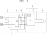
- FIG. 3 is a diagram illustrating a surge path in case where a protection capacitor is provided in accordance with an embodiment.
- a rectification unit 301 includes a first protection capacitor C5 and a second protection capacitor C6 connected between the live terminal L and the neutral terminal N.
- the first protection capacitor C5 and the second protection capacitor C6 are configured such that a value of the first impedance is smaller than a value of the second impedance, and are connected to each other in series on the first path ro1.
- first protection capacitor C5 is connected to the live terminal L and another end of the first capacitor C5 is connected to one end of the second protection capacitor C6. Further, another end of the second protection capacitor C6 is connected to the neutral terminal N.
- the first protection capacitor C5 and the second protection capacitor C6 are designed such that a value of the first impedance including a combined capacitance reactance value of the first protection capacitor C5 and the second protection capacitor C6 can be ignored compared to a value of the second impedance. That is, the capacitances of the first protection capacitor C5 and the second protection capacitor C6 are be designed such that the value of the first impedance is much smaller than the value of the second impedance.
- the surge flows only in the first path ro1. That is, since a surge current having an impedance in which harmonic noise due to a surge is relatively low is discharged through the first path ro1. This may result in improving surge immunity of the control unit 40 and the motor unit 50.
- inner spaces of the first motor M1 and the second motor M2 can be designed to be smaller than or equal to a reference inner space (e.g., 3 mm).
- FIGS. 2 and 3 illustrate only the first motor M1 in the motor unit 50, but the implementation is not limited thereto.
- the second motor M2 may be connected to the ground e.
- the power supply unit 10, the filter unit 20, and the rectification unit 30 have been described as separate configurations, the implementation is not limited thereto.
- the power supply unit 10, the filter unit 20, and the rectification unit 30 may alternatively be included in one configuration.
- the surge protection circuit 1 includes the first protection capacitor C5 and the second protection capacitor C6 which are provided in the rectification unit 301 and connected to each other in a manner that the first impedance value is smaller than the second impedance value. That is, since a surge current having an impedance in which harmonic noise due to a surge is relatively low is discharged through the first path ro1, by virtue of the first protection capacitor C5 and the second protection capacitor C6. This may result in improving surge immunity of the control unit 40 and the motor unit 50.
- the surge protection circuit 1 compared to the related art in which a circuit has been further provided in a motor drive circuit for surge protection, the surge protection circuit 1 according to the implementation which is equipped with only two capacitors can reduce a manufacturing cost of a product, and the inner spaces of the first motor M1 and the second motor M2 can be designed to be 3 mm or less, thereby reducing a volume of the surge protection circuit.
Landscapes
- Engineering & Computer Science (AREA)
- Power Engineering (AREA)
- Water Supply & Treatment (AREA)
- Inverter Devices (AREA)
- Control Of Ac Motors In General (AREA)
Claims (5)
- Überspannungsschutzschaltung (1), umfassend:eine Leistungsversorgungseinheit (10), an die eine erste Leistung angelegt wird;eine Filtereinheit (20), die dazu ausgelegt ist, das Rauschen der ersten Leistung auszufiltern, während sie von einem Strom, der einer Überspannung entspricht, durchflossen wird;eine Gleichrichtereinheit (301), die mit einem Diodenteil (31) und zumindest einem Schutzkondensator (C5, C6) versehen und dazu ausgelegt ist, die erste Leistung in eine zweite Leistung gleichzurichten,eine Steuereinheit (40), die dazu ausgelegt ist, eine Antriebsleistung unter Verwendung der zweiten Leistung entsprechend dem Betriebsmodus zu erzeugen; undeine Motoreinheit (50), die mit zumindest einem Motor (M1, M2) versehen ist, der von der Steuereinheit (40) entsprechend dem Betriebsmodus angesteuert wird und dazu ausgelegt ist, durch die Antriebsleistung angetrieben zu werden,wobei die Überspannungsschutzschaltung (1) dadurch gekennzeichnet ist, dass:die Filtereinheit (20) mit einer Masse verbunden ist, so dass der Strom über die Masse an die Filtereinheit (20) angelegt wird,wobei eine erste Impedanz, bei der die Impedanz der Filtereinheit (20) und die Impedanz der Gleichrichtereinheit (301) kombiniert sind, kleiner ist als eine zweite Impedanz, bei der die Impedanz der Steuereinheit (40) und die Impedanz der Motoreinheit (50) kombiniert sind,wobei die erste Leistung eine Wechselstromleistung, AC ist, die über einen stromführenden Anschluss (L) und einen neutralen Anschluss (N) angelegt wird,wobei die Filtereinheit (20) mit einem ersten Kondensator (C1) und einem zweiten Kondensator (C2) versehen ist, die zwischen dem stromführenden Anschluss (L) und dem neutralen Anschluss (N) in Reihe geschaltet sind,wobei die Masse mit einem Knotenpunkt zwischen dem ersten Kondensator (C1) und dem zweiten Kondensator (C2) verbunden ist,wobei die Gleichrichtereinheit (301) mit einem dritten Kondensator (C3), einem ersten Schutzkondensator (C5) und einem zweiten Schutzkondensator (C6) versehen ist, die zwischen dem stromführenden Anschluss (L) und dem neutralen Anschluss (N) angeschlossen sind,wobei der der Überspannung entsprechende Strom entlang eines Pfades fließt, der aus der Masse und dem ersten bis dritten Kondensator (C1 bis C3), dem ersten Schutzkondensator (C5) und dem zweiten Schutzkondensator (C6) gebildet ist,wobei der dritte Kondensator (C3) zwischen dem Diodenteil (31) und der Steuereinheit (40) parallelgeschaltet ist,wobei ein Ende des ersten Schutzkondensators (C5) mit dem stromführenden Anschluss (L) zwischen dem Diodenteil (31) und der Steuereinheit (40) verbunden ist, ein anderes Ende des ersten Schutzkondensators (C5) mit einem Ende des zweiten Schutzkondensators (C6) verbunden ist und ein anderes Ende des zweiten Schutzkondensators (C6) mit dem neutralen Anschluss (N) zwischen der Filtereinheit (20) und dem Diodenteil (31) verbunden ist, undwobei der dritte Kondensator (C3) mit dem ersten Schutzkondensator (C5) und dem zweiten Schutzkondensator (C6) parallelgeschaltet ist.
- Überspannungsschutzschaltung (1) nach Anspruch 1, wobei die Steuereinheit (40) umfasst:ein Intelligent Power Modul, IPM, das dazu ausgelegt ist, die Antriebsleistung an den zumindest einen Motor (M1, M2) entsprechend dem Betriebsmodus anzulegen; undeinen vierten Kondensator (C4), der mit dem IPM und einer Stromleitung des zumindest einen Motors (M1, M2) verbunden ist.
- Überspannungsschutzschaltung (1) nach Anspruch 2, wobei der vierte Kondensator (C4) ein Kondensator ist, der ein Bootstrapping zum Ansteuern des zumindest einen Motors (M1, M2) durchführt,wobei der Betriebsmodus ein Modus aus Wasserzufuhr, Spülen und Ableiten ist, undwobei das IPM dazu ausgelegt ist, die Antriebsleistung an den zumindest einen Motor (M1, M2) als Reaktion auf einen der Modi Wasserzufuhr, Spülen und Ableiten anzulegen.
- Überspannungsschutzschaltung (1) nach Anspruch 3, wobei die Motoreinheit (50) einen ersten Motor (M1) und einen zweiten Motor (M2) umfasst, und
wobei das IPM dazu ausgelegt ist, die Antriebsleistung an den ersten Motor (M1) oder den zweiten Motor (M2) in Reaktion auf einen der Modi Wasserzufuhr, Spülen und Ableiten anzulegen. - Geschirrspüler mit einer Überspannungsschutzschaltung (1) nach einem der Ansprüche 1 bis 4.
Applications Claiming Priority (1)
| Application Number | Priority Date | Filing Date | Title |
|---|---|---|---|
| KR1020190070908A KR102745006B1 (ko) | 2019-06-14 | 2019-06-14 | 서지 보호 회로 및 서지 보호 회로를 포함하는 식기 세척기 |
Publications (2)
| Publication Number | Publication Date |
|---|---|
| EP3751690A1 EP3751690A1 (de) | 2020-12-16 |
| EP3751690B1 true EP3751690B1 (de) | 2024-08-28 |
Family
ID=71094107
Family Applications (1)
| Application Number | Title | Priority Date | Filing Date |
|---|---|---|---|
| EP20179605.9A Active EP3751690B1 (de) | 2019-06-14 | 2020-06-12 | Überspannungsschutzschaltung und geschirrspülmaschine damit |
Country Status (3)
| Country | Link |
|---|---|
| US (1) | US11296495B2 (de) |
| EP (1) | EP3751690B1 (de) |
| KR (1) | KR102745006B1 (de) |
Families Citing this family (2)
| Publication number | Priority date | Publication date | Assignee | Title |
|---|---|---|---|---|
| CN113488977B (zh) * | 2021-07-12 | 2023-06-13 | 珠海格力电器股份有限公司 | 一种电机的热插拔保护装置和电机 |
| TWI827379B (zh) | 2022-11-23 | 2023-12-21 | 財團法人工業技術研究院 | 電動車輛之馬達控制器及馬達控制方法 |
Family Cites Families (12)
| Publication number | Priority date | Publication date | Assignee | Title |
|---|---|---|---|---|
| US4843515A (en) * | 1987-04-20 | 1989-06-27 | Keytek Instrument Corp. | Surge undershoot eliminator |
| EP1258980B1 (de) * | 2001-05-17 | 2005-12-07 | STMicroelectronics S.r.l. | Treiberschaltung und Verfahren zur Verhinderung von Überspannungen auf Versorgungsleitungen während des Betriebes eines Gleichstrommotors |
| US7940506B2 (en) * | 2003-03-05 | 2011-05-10 | Dollar Energy Group, Inc. | Automated AC line filter and surge suppression apparatus and method |
| EP2360820B1 (de) | 2009-12-31 | 2018-03-28 | Nxp B.V. | Überspannungsschutzschaltung |
| US8520355B2 (en) * | 2010-07-27 | 2013-08-27 | Regal Beloit America, Inc. | Methods and systems for transient voltage protection |
| KR20130081727A (ko) * | 2011-12-28 | 2013-07-18 | 삼성전기주식회사 | 과전원 보호 기능을 구비한 전원 장치 |
| KR101474150B1 (ko) * | 2013-07-01 | 2014-12-18 | 삼성전기주식회사 | 서지 보호 회로를 구비한 전원장치 |
| KR20150052446A (ko) * | 2013-11-05 | 2015-05-14 | 주식회사 아모센스 | 전원장치용 보호회로 |
| KR101608135B1 (ko) * | 2014-05-22 | 2016-03-31 | 루멘전광 주식회사 | 방사선 지역용 led 구동회로 |
| KR101728415B1 (ko) * | 2015-06-25 | 2017-04-28 | (주)엠포스 | 보호 기능을 가지는 교류 직결형 엘이디 조명 회로 |
| KR20170076266A (ko) * | 2015-12-24 | 2017-07-04 | 주식회사 젬 | 전원 장치용 서지 보호회로 |
| KR102379057B1 (ko) * | 2017-08-21 | 2022-03-28 | 현대자동차주식회사 | 능동 emi 필터 및 그를 포함하는 차량 |
-
2019
- 2019-06-14 KR KR1020190070908A patent/KR102745006B1/ko active Active
-
2020
- 2020-06-12 US US16/900,032 patent/US11296495B2/en active Active
- 2020-06-12 EP EP20179605.9A patent/EP3751690B1/de active Active
Also Published As
| Publication number | Publication date |
|---|---|
| EP3751690A1 (de) | 2020-12-16 |
| US20200395749A1 (en) | 2020-12-17 |
| US11296495B2 (en) | 2022-04-05 |
| KR20200143070A (ko) | 2020-12-23 |
| KR102745006B1 (ko) | 2024-12-20 |
Similar Documents
| Publication | Publication Date | Title |
|---|---|---|
| CN102668364B (zh) | 在同步整流器中避免甩负载过电压 | |
| JP5444142B2 (ja) | 電力変換器、及びこれを用いたモータ駆動装置 | |
| US20130049659A1 (en) | Circuit arrangement for modular drive power converters | |
| CN109417354B (zh) | 三电平逆变器 | |
| US11296495B2 (en) | Surge protection circuit and dishwasher including the same | |
| JP3582545B2 (ja) | ブリッジ形電力変換装置 | |
| JP7537183B2 (ja) | 半導体装置 | |
| CN107949980B (zh) | 电压转换器,电的驱动系统和用于减小干扰电压的方法 | |
| US9374006B2 (en) | Three-channel high-side gate driver having startup circuit and configurable outputs | |
| JP2022077909A (ja) | 半導体装置 | |
| EP3566293B1 (de) | Erdungsschema für stromwandler mit siliciumcarbid-mosfets und verfahren | |
| CN108521843A (zh) | 滤波安排 | |
| CN107636944B (zh) | 电动机系统及其控制方法 | |
| CN205081635U (zh) | 用于减小和/或避免电机中的有害的轴承电流的装置 | |
| US6008560A (en) | Inverter driven motor having winding termination reducing EMI | |
| JP7003449B2 (ja) | 車載装置 | |
| JP7086268B2 (ja) | 回転電機、回転電機の駆動装置、および回転電機の駆動システム | |
| KR100546430B1 (ko) | 변환회로 장치용 부하측 필터 장치 | |
| JP2003324966A (ja) | インバータ駆動回路 | |
| US7030587B2 (en) | Configuration of converter switches and machine coils of a switched reluctance machine | |
| CN101346874B (zh) | 具有去耦相的旋转电机 | |
| KR20200143065A (ko) | 서지 보호 회로 및 서지 보호 회로를 포함하는 식기 세척기 | |
| JP4904851B2 (ja) | 過電圧保護回路を備えた半導体装置 | |
| WO2017158783A1 (ja) | 電力変換装置及びこれを用いた空気調和装置 | |
| US20220038043A1 (en) | Electromagnetic filtering of a control circuit of an electric motor |
Legal Events
| Date | Code | Title | Description |
|---|---|---|---|
| PUAI | Public reference made under article 153(3) epc to a published international application that has entered the european phase |
Free format text: ORIGINAL CODE: 0009012 |
|
| STAA | Information on the status of an ep patent application or granted ep patent |
Free format text: STATUS: THE APPLICATION HAS BEEN PUBLISHED |
|
| AK | Designated contracting states |
Kind code of ref document: A1 Designated state(s): AL AT BE BG CH CY CZ DE DK EE ES FI FR GB GR HR HU IE IS IT LI LT LU LV MC MK MT NL NO PL PT RO RS SE SI SK SM TR |
|
| AX | Request for extension of the european patent |
Extension state: BA ME |
|
| STAA | Information on the status of an ep patent application or granted ep patent |
Free format text: STATUS: REQUEST FOR EXAMINATION WAS MADE |
|
| 17P | Request for examination filed |
Effective date: 20210614 |
|
| RBV | Designated contracting states (corrected) |
Designated state(s): AL AT BE BG CH CY CZ DE DK EE ES FI FR GB GR HR HU IE IS IT LI LT LU LV MC MK MT NL NO PL PT RO RS SE SI SK SM TR |
|
| STAA | Information on the status of an ep patent application or granted ep patent |
Free format text: STATUS: EXAMINATION IS IN PROGRESS |
|
| 17Q | First examination report despatched |
Effective date: 20220809 |
|
| GRAP | Despatch of communication of intention to grant a patent |
Free format text: ORIGINAL CODE: EPIDOSNIGR1 |
|
| STAA | Information on the status of an ep patent application or granted ep patent |
Free format text: STATUS: GRANT OF PATENT IS INTENDED |
|
| INTG | Intention to grant announced |
Effective date: 20240410 |
|
| GRAS | Grant fee paid |
Free format text: ORIGINAL CODE: EPIDOSNIGR3 |
|
| GRAA | (expected) grant |
Free format text: ORIGINAL CODE: 0009210 |
|
| STAA | Information on the status of an ep patent application or granted ep patent |
Free format text: STATUS: THE PATENT HAS BEEN GRANTED |
|
| AK | Designated contracting states |
Kind code of ref document: B1 Designated state(s): AL AT BE BG CH CY CZ DE DK EE ES FI FR GB GR HR HU IE IS IT LI LT LU LV MC MK MT NL NO PL PT RO RS SE SI SK SM TR |
|
| REG | Reference to a national code |
Ref country code: CH Ref legal event code: EP |
|
| REG | Reference to a national code |
Ref country code: DE Ref legal event code: R096 Ref document number: 602020036522 Country of ref document: DE |
|
| REG | Reference to a national code |
Ref country code: IE Ref legal event code: FG4D |
|
| REG | Reference to a national code |
Ref country code: LT Ref legal event code: MG9D |
|
| PG25 | Lapsed in a contracting state [announced via postgrant information from national office to epo] |
Ref country code: NO Free format text: LAPSE BECAUSE OF FAILURE TO SUBMIT A TRANSLATION OF THE DESCRIPTION OR TO PAY THE FEE WITHIN THE PRESCRIBED TIME-LIMIT Effective date: 20241128 |
|
| REG | Reference to a national code |
Ref country code: AT Ref legal event code: MK05 Ref document number: 1719043 Country of ref document: AT Kind code of ref document: T Effective date: 20240828 |
|
| PG25 | Lapsed in a contracting state [announced via postgrant information from national office to epo] |
Ref country code: NL Free format text: LAPSE BECAUSE OF FAILURE TO SUBMIT A TRANSLATION OF THE DESCRIPTION OR TO PAY THE FEE WITHIN THE PRESCRIBED TIME-LIMIT Effective date: 20240828 Ref country code: FI Free format text: LAPSE BECAUSE OF FAILURE TO SUBMIT A TRANSLATION OF THE DESCRIPTION OR TO PAY THE FEE WITHIN THE PRESCRIBED TIME-LIMIT Effective date: 20240828 Ref country code: PT Free format text: LAPSE BECAUSE OF FAILURE TO SUBMIT A TRANSLATION OF THE DESCRIPTION OR TO PAY THE FEE WITHIN THE PRESCRIBED TIME-LIMIT Effective date: 20241230 Ref country code: GR Free format text: LAPSE BECAUSE OF FAILURE TO SUBMIT A TRANSLATION OF THE DESCRIPTION OR TO PAY THE FEE WITHIN THE PRESCRIBED TIME-LIMIT Effective date: 20241129 Ref country code: PL Free format text: LAPSE BECAUSE OF FAILURE TO SUBMIT A TRANSLATION OF THE DESCRIPTION OR TO PAY THE FEE WITHIN THE PRESCRIBED TIME-LIMIT Effective date: 20240828 |
|
| PG25 | Lapsed in a contracting state [announced via postgrant information from national office to epo] |
Ref country code: BG Free format text: LAPSE BECAUSE OF FAILURE TO SUBMIT A TRANSLATION OF THE DESCRIPTION OR TO PAY THE FEE WITHIN THE PRESCRIBED TIME-LIMIT Effective date: 20240828 |
|
| PG25 | Lapsed in a contracting state [announced via postgrant information from national office to epo] |
Ref country code: LV Free format text: LAPSE BECAUSE OF FAILURE TO SUBMIT A TRANSLATION OF THE DESCRIPTION OR TO PAY THE FEE WITHIN THE PRESCRIBED TIME-LIMIT Effective date: 20240828 |
|
| REG | Reference to a national code |
Ref country code: NL Ref legal event code: MP Effective date: 20240828 |
|
| PG25 | Lapsed in a contracting state [announced via postgrant information from national office to epo] |
Ref country code: IS Free format text: LAPSE BECAUSE OF FAILURE TO SUBMIT A TRANSLATION OF THE DESCRIPTION OR TO PAY THE FEE WITHIN THE PRESCRIBED TIME-LIMIT Effective date: 20241228 Ref country code: AT Free format text: LAPSE BECAUSE OF FAILURE TO SUBMIT A TRANSLATION OF THE DESCRIPTION OR TO PAY THE FEE WITHIN THE PRESCRIBED TIME-LIMIT Effective date: 20240828 |
|
| PG25 | Lapsed in a contracting state [announced via postgrant information from national office to epo] |
Ref country code: HR Free format text: LAPSE BECAUSE OF FAILURE TO SUBMIT A TRANSLATION OF THE DESCRIPTION OR TO PAY THE FEE WITHIN THE PRESCRIBED TIME-LIMIT Effective date: 20240828 |
|
| PG25 | Lapsed in a contracting state [announced via postgrant information from national office to epo] |
Ref country code: ES Free format text: LAPSE BECAUSE OF FAILURE TO SUBMIT A TRANSLATION OF THE DESCRIPTION OR TO PAY THE FEE WITHIN THE PRESCRIBED TIME-LIMIT Effective date: 20240828 Ref country code: RS Free format text: LAPSE BECAUSE OF FAILURE TO SUBMIT A TRANSLATION OF THE DESCRIPTION OR TO PAY THE FEE WITHIN THE PRESCRIBED TIME-LIMIT Effective date: 20241128 |
|
| PG25 | Lapsed in a contracting state [announced via postgrant information from national office to epo] |
Ref country code: RS Free format text: LAPSE BECAUSE OF FAILURE TO SUBMIT A TRANSLATION OF THE DESCRIPTION OR TO PAY THE FEE WITHIN THE PRESCRIBED TIME-LIMIT Effective date: 20241128 Ref country code: PT Free format text: LAPSE BECAUSE OF FAILURE TO SUBMIT A TRANSLATION OF THE DESCRIPTION OR TO PAY THE FEE WITHIN THE PRESCRIBED TIME-LIMIT Effective date: 20241230 Ref country code: PL Free format text: LAPSE BECAUSE OF FAILURE TO SUBMIT A TRANSLATION OF THE DESCRIPTION OR TO PAY THE FEE WITHIN THE PRESCRIBED TIME-LIMIT Effective date: 20240828 Ref country code: NO Free format text: LAPSE BECAUSE OF FAILURE TO SUBMIT A TRANSLATION OF THE DESCRIPTION OR TO PAY THE FEE WITHIN THE PRESCRIBED TIME-LIMIT Effective date: 20241128 Ref country code: NL Free format text: LAPSE BECAUSE OF FAILURE TO SUBMIT A TRANSLATION OF THE DESCRIPTION OR TO PAY THE FEE WITHIN THE PRESCRIBED TIME-LIMIT Effective date: 20240828 Ref country code: LV Free format text: LAPSE BECAUSE OF FAILURE TO SUBMIT A TRANSLATION OF THE DESCRIPTION OR TO PAY THE FEE WITHIN THE PRESCRIBED TIME-LIMIT Effective date: 20240828 Ref country code: IS Free format text: LAPSE BECAUSE OF FAILURE TO SUBMIT A TRANSLATION OF THE DESCRIPTION OR TO PAY THE FEE WITHIN THE PRESCRIBED TIME-LIMIT Effective date: 20241228 Ref country code: HR Free format text: LAPSE BECAUSE OF FAILURE TO SUBMIT A TRANSLATION OF THE DESCRIPTION OR TO PAY THE FEE WITHIN THE PRESCRIBED TIME-LIMIT Effective date: 20240828 Ref country code: GR Free format text: LAPSE BECAUSE OF FAILURE TO SUBMIT A TRANSLATION OF THE DESCRIPTION OR TO PAY THE FEE WITHIN THE PRESCRIBED TIME-LIMIT Effective date: 20241129 Ref country code: FI Free format text: LAPSE BECAUSE OF FAILURE TO SUBMIT A TRANSLATION OF THE DESCRIPTION OR TO PAY THE FEE WITHIN THE PRESCRIBED TIME-LIMIT Effective date: 20240828 Ref country code: ES Free format text: LAPSE BECAUSE OF FAILURE TO SUBMIT A TRANSLATION OF THE DESCRIPTION OR TO PAY THE FEE WITHIN THE PRESCRIBED TIME-LIMIT Effective date: 20240828 Ref country code: BG Free format text: LAPSE BECAUSE OF FAILURE TO SUBMIT A TRANSLATION OF THE DESCRIPTION OR TO PAY THE FEE WITHIN THE PRESCRIBED TIME-LIMIT Effective date: 20240828 Ref country code: AT Free format text: LAPSE BECAUSE OF FAILURE TO SUBMIT A TRANSLATION OF THE DESCRIPTION OR TO PAY THE FEE WITHIN THE PRESCRIBED TIME-LIMIT Effective date: 20240828 |
|
| PG25 | Lapsed in a contracting state [announced via postgrant information from national office to epo] |
Ref country code: SM Free format text: LAPSE BECAUSE OF FAILURE TO SUBMIT A TRANSLATION OF THE DESCRIPTION OR TO PAY THE FEE WITHIN THE PRESCRIBED TIME-LIMIT Effective date: 20240828 Ref country code: RO Free format text: LAPSE BECAUSE OF FAILURE TO SUBMIT A TRANSLATION OF THE DESCRIPTION OR TO PAY THE FEE WITHIN THE PRESCRIBED TIME-LIMIT Effective date: 20240828 Ref country code: DK Free format text: LAPSE BECAUSE OF FAILURE TO SUBMIT A TRANSLATION OF THE DESCRIPTION OR TO PAY THE FEE WITHIN THE PRESCRIBED TIME-LIMIT Effective date: 20240828 |
|
| PG25 | Lapsed in a contracting state [announced via postgrant information from national office to epo] |
Ref country code: EE Free format text: LAPSE BECAUSE OF FAILURE TO SUBMIT A TRANSLATION OF THE DESCRIPTION OR TO PAY THE FEE WITHIN THE PRESCRIBED TIME-LIMIT Effective date: 20240828 |
|
| PG25 | Lapsed in a contracting state [announced via postgrant information from national office to epo] |
Ref country code: CZ Free format text: LAPSE BECAUSE OF FAILURE TO SUBMIT A TRANSLATION OF THE DESCRIPTION OR TO PAY THE FEE WITHIN THE PRESCRIBED TIME-LIMIT Effective date: 20240828 |
|
| PG25 | Lapsed in a contracting state [announced via postgrant information from national office to epo] |
Ref country code: IT Free format text: LAPSE BECAUSE OF FAILURE TO SUBMIT A TRANSLATION OF THE DESCRIPTION OR TO PAY THE FEE WITHIN THE PRESCRIBED TIME-LIMIT Effective date: 20240828 Ref country code: SK Free format text: LAPSE BECAUSE OF FAILURE TO SUBMIT A TRANSLATION OF THE DESCRIPTION OR TO PAY THE FEE WITHIN THE PRESCRIBED TIME-LIMIT Effective date: 20240828 |
|
| REG | Reference to a national code |
Ref country code: DE Ref legal event code: R097 Ref document number: 602020036522 Country of ref document: DE |
|
| PLBE | No opposition filed within time limit |
Free format text: ORIGINAL CODE: 0009261 |
|
| STAA | Information on the status of an ep patent application or granted ep patent |
Free format text: STATUS: NO OPPOSITION FILED WITHIN TIME LIMIT |
|
| PGFP | Annual fee paid to national office [announced via postgrant information from national office to epo] |
Ref country code: DE Payment date: 20250508 Year of fee payment: 6 |
|
| 26N | No opposition filed |
Effective date: 20250530 |
|
| PG25 | Lapsed in a contracting state [announced via postgrant information from national office to epo] |
Ref country code: SE Free format text: LAPSE BECAUSE OF FAILURE TO SUBMIT A TRANSLATION OF THE DESCRIPTION OR TO PAY THE FEE WITHIN THE PRESCRIBED TIME-LIMIT Effective date: 20240828 |
|
| REG | Reference to a national code |
Ref country code: CH Ref legal event code: H13 Free format text: ST27 STATUS EVENT CODE: U-0-0-H10-H13 (AS PROVIDED BY THE NATIONAL OFFICE) Effective date: 20260127 |
|
| PG25 | Lapsed in a contracting state [announced via postgrant information from national office to epo] |
Ref country code: MC Free format text: LAPSE BECAUSE OF FAILURE TO SUBMIT A TRANSLATION OF THE DESCRIPTION OR TO PAY THE FEE WITHIN THE PRESCRIBED TIME-LIMIT Effective date: 20240828 |
|
| PG25 | Lapsed in a contracting state [announced via postgrant information from national office to epo] |
Ref country code: LU Free format text: LAPSE BECAUSE OF NON-PAYMENT OF DUE FEES Effective date: 20250612 |
|
| GBPC | Gb: european patent ceased through non-payment of renewal fee |
Effective date: 20250612 |
|
| REG | Reference to a national code |
Ref country code: BE Ref legal event code: MM Effective date: 20250630 |
|
| PG25 | Lapsed in a contracting state [announced via postgrant information from national office to epo] |
Ref country code: GB Free format text: LAPSE BECAUSE OF NON-PAYMENT OF DUE FEES Effective date: 20250612 |
|
| PG25 | Lapsed in a contracting state [announced via postgrant information from national office to epo] |
Ref country code: IE Free format text: LAPSE BECAUSE OF NON-PAYMENT OF DUE FEES Effective date: 20250612 |
|
| PG25 | Lapsed in a contracting state [announced via postgrant information from national office to epo] |
Ref country code: BE Free format text: LAPSE BECAUSE OF NON-PAYMENT OF DUE FEES Effective date: 20250630 |
|
| PG25 | Lapsed in a contracting state [announced via postgrant information from national office to epo] |
Ref country code: FR Free format text: LAPSE BECAUSE OF NON-PAYMENT OF DUE FEES Effective date: 20250630 |
|
| PG25 | Lapsed in a contracting state [announced via postgrant information from national office to epo] |
Ref country code: CH Free format text: LAPSE BECAUSE OF NON-PAYMENT OF DUE FEES Effective date: 20250630 |