EP3566293B1 - Erdungsschema für stromwandler mit siliciumcarbid-mosfets und verfahren - Google Patents
Erdungsschema für stromwandler mit siliciumcarbid-mosfets und verfahren Download PDFInfo
- Publication number
- EP3566293B1 EP3566293B1 EP17890167.4A EP17890167A EP3566293B1 EP 3566293 B1 EP3566293 B1 EP 3566293B1 EP 17890167 A EP17890167 A EP 17890167A EP 3566293 B1 EP3566293 B1 EP 3566293B1
- Authority
- EP
- European Patent Office
- Prior art keywords
- power
- ground
- high impedance
- rotor
- voltage
- Prior art date
- Legal status (The legal status is an assumption and is not a legal conclusion. Google has not performed a legal analysis and makes no representation as to the accuracy of the status listed.)
- Active
Links
Images




Classifications
-
- H—ELECTRICITY
- H02—GENERATION; CONVERSION OR DISTRIBUTION OF ELECTRIC POWER
- H02P—CONTROL OR REGULATION OF ELECTRIC MOTORS, ELECTRIC GENERATORS OR DYNAMO-ELECTRIC CONVERTERS; CONTROLLING TRANSFORMERS, REACTORS OR CHOKE COILS
- H02P9/00—Arrangements for controlling electric generators for the purpose of obtaining a desired output
- H02P9/007—Control circuits for doubly fed generators
-
- F—MECHANICAL ENGINEERING; LIGHTING; HEATING; WEAPONS; BLASTING
- F03—MACHINES OR ENGINES FOR LIQUIDS; WIND, SPRING, OR WEIGHT MOTORS; PRODUCING MECHANICAL POWER OR A REACTIVE PROPULSIVE THRUST, NOT OTHERWISE PROVIDED FOR
- F03D—WIND MOTORS
- F03D9/00—Adaptations of wind motors for special use; Combinations of wind motors with apparatus driven thereby; Wind motors specially adapted for installation in particular locations
- F03D9/20—Wind motors characterised by the driven apparatus
- F03D9/25—Wind motors characterised by the driven apparatus the apparatus being an electrical generator
- F03D9/255—Wind motors characterised by the driven apparatus the apparatus being an electrical generator connected to electrical distribution networks; Arrangements therefor
-
- H—ELECTRICITY
- H02—GENERATION; CONVERSION OR DISTRIBUTION OF ELECTRIC POWER
- H02K—DYNAMO-ELECTRIC MACHINES
- H02K11/00—Structural association of dynamo-electric machines with electric components or with devices for shielding, monitoring or protection
- H02K11/02—Structural association of dynamo-electric machines with electric components or with devices for shielding, monitoring or protection for suppression of electromagnetic interference
-
- H—ELECTRICITY
- H02—GENERATION; CONVERSION OR DISTRIBUTION OF ELECTRIC POWER
- H02K—DYNAMO-ELECTRIC MACHINES
- H02K11/00—Structural association of dynamo-electric machines with electric components or with devices for shielding, monitoring or protection
- H02K11/40—Structural association with grounding devices
-
- H—ELECTRICITY
- H02—GENERATION; CONVERSION OR DISTRIBUTION OF ELECTRIC POWER
- H02K—DYNAMO-ELECTRIC MACHINES
- H02K7/00—Arrangements for handling mechanical energy structurally associated with dynamo-electric machines, e.g. structural association with mechanical driving motors or auxiliary dynamo-electric machines
- H02K7/18—Structural association of electric generators with mechanical driving motors, e.g. with turbines
- H02K7/1807—Rotary generators
- H02K7/1823—Rotary generators structurally associated with turbines or similar engines
- H02K7/183—Rotary generators structurally associated with turbines or similar engines wherein the turbine is a wind turbine
- H02K7/1838—Generators mounted in a nacelle or similar structure of a horizontal axis wind turbine
-
- Y—GENERAL TAGGING OF NEW TECHNOLOGICAL DEVELOPMENTS; GENERAL TAGGING OF CROSS-SECTIONAL TECHNOLOGIES SPANNING OVER SEVERAL SECTIONS OF THE IPC; TECHNICAL SUBJECTS COVERED BY FORMER USPC CROSS-REFERENCE ART COLLECTIONS [XRACs] AND DIGESTS
- Y02—TECHNOLOGIES OR APPLICATIONS FOR MITIGATION OR ADAPTATION AGAINST CLIMATE CHANGE
- Y02E—REDUCTION OF GREENHOUSE GAS [GHG] EMISSIONS, RELATED TO ENERGY GENERATION, TRANSMISSION OR DISTRIBUTION
- Y02E10/00—Energy generation through renewable energy sources
- Y02E10/70—Wind energy
- Y02E10/72—Wind turbines with rotation axis in wind direction
Definitions
- the present subject matter relates generally to power systems, and more particularly to systems and methods for grounding a power system including power converters utilizing silicon carbide MOSFETs.
- the power generation system can further be grounded by connecting at least one pole of the DC link to a ground.
- a DC link can include a first pole at a first voltage and a second pole at a second voltage. Either the first pole or the second pole can be electrically connected to a ground.
- the power generation system can be electrically grounded to shunt a leakage current associated with the isolation transformer through the at least one pole of the DC link connected to the ground.
- a high impedance resistor can be connected to the at least one pole of the DC link and the ground.
- the power generation system can be electrically grounded to shunt the leakage current associated with the isolation transformer to the ground through the high impedance resistor connected to the at least one pole of the DC link.
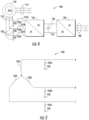
- the rotor side converter 166 and/or the line side converter 168 can include a plurality of conversion modules, each associated with a an output phase of the multiphase power, as will be discussed in more detail with respect to FIGS. 2 and 3 .
- the rotor side converter 166 and the line side converter 168 can be coupled via a DC link 126 across which can be a DC link capacitor 138.
- the DC link 126 can include a dynamic brake (not shown).
- the dynamic brake can include a switching element (e.g., an IGBT) coupled in series with a dissipative element (e.g., a resistor).
- the switching element can be controlled using pulse width modulation techniques via one or more control devices (e.g., controller 174 or control system 176) to control the voltage on the DC link 126.
- the DC link 126 can include a plurality of resistors (e.g., two resistors) coupled in series between the positive and negative bus.
- a ground can be coupled at a midpoint between the resistors.
- the AC power provided to the power converter 162 via the rotor bus 156 can be a low voltage ("LV") AC power.
- LV AC power can be an alternating current power less than or equal to about 1.5 kilovolts.
- the rotor side power converter 166 converts the LV AC power provided from the rotor bus 156 into DC power and provides the DC power to the DC link 126.
- Switching devices e.g. SiC MOSFETs and/or IGBTs
- Such DC power can be a LV DC power.
- the power converter 162 can be configured to convert the LV power to MV AC power.
- the line side converter 168 converts the LV DC power on the DC link 126 into a MV AC power suitable for the electrical grid 184.
- SiC MOSFETs used in bridge circuits of the line side power converter 168 can be modulated to convert the DC power on the DC link 126 into AC power on the line side bus 188.
- SiC MOSFETs can be operated at a higher switching frequency than conventional IGBTs.
- one or more isolation transformers coupled to one or more of the bridge circuits can be configured to step the voltage up or down as needed.
- the high impedance resistor can be selected to carry a leakage current associated with the isolation transformer of the power converter.
- the high impedance resistor 420 can be a resistor selected to carry the leakage current across insulation barriers from all leakage current sources, including leakage current caused by high-frequency AC sources, such as SiC MOSFETs, through stray capacitances in the insulation system.
- the high impedance resistor(s) 420 can be selected based on the ratings and capabilities of surge protection devices, such as MOVs (not shown). For example, the high impedance resistor 420 can be selected to ensure that MOVs do not end up carrying the leakage current.
- power system 500 can correspond to the power system 400 depicted in FIG. 4 . Elements that are the same or similar to those in previous FIGS. are labeled with the same reference numerals.
- power system 500 can include a multiphase DFIG 120 connected in a Wye configuration.
- DFIG 120 includes three rotor windings for each of the three rotor phases, rotor winding 120A configured to generate power for phase A, rotor winding 120B configured to generate power for phase B, and rotor winding 120C configured to generate power for phase C.
- a high impedance resistor 420 can be electrically connected to one or more phases of the DFIG 120. For example, as shown a first high impedance resistor 420A is electrically connected between phase A and the ground 430, a second high impedance resistor 420B is electrically connected between phase B and the ground 430, and a third high impedance resistor 420C is electrically connected between phase C and the ground 430.
- the leakage current from a power converter 162 can be shunted to ground 430 through these high impedance resistors 420.
- the control device can be configured to determine whether a voltage or current imbalance exists based on the sensed values, and further can be configured to shut down the power converter 162, open one or more switches (not shown), or perform other control actions to electrically isolate the faulted power generation unit when the control device 174 determines a voltage or current imbalance across the high impedance resistors 420 exists.
- power system 600 can correspond to the power system 400 depicted in FIG. 4 . Elements that are the same or similar to those in previous FIGS. are labeled with the same reference numerals.
- power system 600 can include a multiphase DFIG 120 connected in a Wye configuration.
- DFIG 120 includes three rotor windings for each of the three phases, rotor winding 120A configured to generate power for phase A, rotor winding 120B configured to generate power for phase B, and rotor winding 120C configured to generate power for phase C.
- the three phases of the DFIG 120 connected in a Wye configuration can together define a midpoint M.
- a neutral conductor 610 can be electrically connected to the midpoint M and the ground 430.
- a neutral conductor 610 is electrically connected between the midpoint M and the ground 430.
- a high impedance resistor 420 is electrically connected to the neutral conductor 610 between the midpoint M and the ground 430.
- the neutral conductor 610 can be electrically connected between the midpoint M and the ground 430 without a high impedance resistor 420.
- the power generation system 600 can be electrically grounded to shunt a leakage current associated with the isolation transformer of the power converter 162 to the ground 430 through the neutral conductor 610.
- the power generation system 600 can be electrically grounded to shunt a leakage current associated with the isolation transformer and other components of the power converter 162 to the ground 430 through the high impedance resistor 420.
- a high impedance resistor 420 can be electrically connected to one or more phases of the DFIG 120. For example, as shown a first high impedance resistor 420A is electrically connected between phase A and the ground 430, a second high impedance resistor 420B is electrically connected between phase B and the ground 430, and a third high impedance resistor 420C is electrically connected between phase C and the ground 430.
- the leakage current from a power converter 162 can be shunted to ground 430 through these high impedance resistors 420.
- a control device such as a control device 174
- each phase can include a high impedance resistor 420 connected between the phase and the ground 430.
- a voltage or current sensor can be configured to sense a voltage across and/or current through the high impedance resistors 420. Further, the sensors can be configured to provide the sensed values to the control device, such as a control device 174.
- the control device can be configured to determine whether a voltage or current imbalance exists based on the sensed values, and further can be configured to shut down the power converter 162 when the control device 174 determines a voltage and/or current imbalance exists across the high impedance resistors 420.
- a DFIG 120 includes a rotor connected to a rotor side bus 156 and a stator connected to a stator side bus 154.
- at least one phase of a multiphase power provided by a rotor of a DFIG 120 can be connected to a filter 410.
- the filter 410 can be, for example, and inductor 411 and a capacitor 412, wherein the capacitor 412 is electrically connected to a ground 430.
- the at least one filter 410 can be electrically connected to the at least one phase of the rotor.
- each phase of the rotor can be electrically connected to a filter 410.
- Each filter 410 can include an inductor 411 and a capacitor 412.
- phase A of the three-phase power from the rotor includes a first filter 410A, which includes an inductor 411A electrically connected between the rotor side converter 166 and the rotor side bus 156. Additionally, the first filter 410A includes a capacitor 412A electrically connected between the phase A of the rotor and the ground 430.
- phases B and C of the three-phase power from the rotor include a second filter 410B for phase B, and a third filter 410C for phase C, respectively.
- the power generation system 800 can be electrically grounded to shunt a leakage current associated with an isolation transformer of a power converter 162, such as an isolation transformer 226 of a line side converter 168, to the ground 430 through the capacitor 412 of each filter. Further, in applications in which only one phase includes a filter 410 electrically connected to the at least one phase, the power generation system 800 can be electrically grounded to shunt a leakage current associated with an isolation transformer of a power converter 162 to a ground 430 through the capacitor 412 of the at least one filter 410.
- a DFIG 120 includes a rotor connected to a rotor side bus 156 and a stator connected to a stator side bus 154.
- Each phase of three-phase power output from the rotor is filtered by a filter 410, such as a first filter 410 A for phase A, a second filter 410 B for phase B, and a third filter 410 C for phase C.
- the three-phase power from the rotor side bus 156 is provided to the rotor side converter 166.
- phase C is electrically connected to a ground 430.
- any number of phases can be electrically connected to the ground 430.
- a DFIG 120 includes a rotor connected to the rotor side bus 156 and a stator connected to a stator side bus 154.
- the rotor side bus 156 can be, for example, a LV bus.
- a stator side bus 154 can be, for example, a MV bus.
- the DFIG 120 can be configured to generate a LV AC power and provide the LV AC power to the rotor side bus 156.
- Rotor side converter 166 can be, for example, a two level AC to DC power converter configured to convert the three-phase alternating current power to a LV DC power, and can provide the DC power to a DC link 126.
- a DC capacitor 138 can be electrically connected to the DC link 126.
- a line side converter 168 can be coupled to the DC link 126, and configured to receive DC power from the DC link and convert it to a multiphase MV AC power suitable for a grid 184.
- the line side converter 168 can be, for example, a DC to DC to AC converter comprising one or more SiC MOSFETs and an isolation transformer, as depicted in FIG. 3 .
- At least one pole of the DC link 126 can be connected to a ground 430.
- the DC link can be connected directly to a ground 430, and the power generation system 1000 can be electrically grounded to shunt a leakage current to the ground 430 through the at least one pole of the DC link 126 connected to the ground 430.
- a tap to provide power for auxiliary loads can be coupled to the DC link 126.
- an auxiliary inverter can be coupled to the DC link 126 to provide power to one or more auxiliary loads.
- a filter can be included at the output of the auxiliary inverter.
- a filter can include an inductor and a filter capacitor. In such a configuration, the neutral of the filter capacitor can be electrically connected to a ground, which can allow for a leakage current to be shunted to ground.
- the DC power source can be connected to the DC link 126.
- a high impedance resistor such as a high impedance resistor 420, can be electrically connected between the at least one pole of the DC link 126 and the ground 430.
- the power generation system can be electrically grounded to shunt a leakage current from a power converter to the ground 430 through the high impedance resistor connected to the at least one pole of the DC link 126.
- the method (1100) can include generating three-phase alternating current power at a first voltage with a power generator.
- the power generator can include a multiphase rotor and stator.
- the phases of the rotor can be configured in a delta or Wye configuration.
- Each phase of the rotor can include a high impedance resistor electrically connected to the phase and a ground.
- each phase of a rotor can include a high impedance resistor 420 connected between the phase and a ground 430.
- the DC to DC to AC power converter can include one or more SiC MOSFETs and an isolation transformer.
- the power converter can be configured to convert the three-phase alternating current power at the first voltage to three-phase alternating current power at a second voltage.
- the power converter can be a power converter 162 configured to convert a LV AC power to a MV AC power suitable for a grid 184.
- the method (1100) can include shutting the power converter down, open one or more switches (not shown), or perform other control actions to electrically isolate the faulted power generation unit by the control device to protect the power converter.
- a control device 174 can disconnect a power converter 162 from a power generation system 100 in order to protect the power converter 162 from a fault current.
- the systems and methods according to example embodiments of the present disclosure can have a technical effect of shunting a leakage current associated with an isolation transformer and other components in a power converter to a ground, and further, in applications in which one or more high impedance resistors are used, can allow for voltage and current imbalance detection and system protection schemes to be implemented.
- FIG. 12 depicts an example computing system 1200 according to example embodiments of the present disclosure.
- the computing system 1200 can be used, for example, as a control device 174 in a power generation system.
- the computing system 1200 can include one or more computing device(s) 1210.
- the computing device(s) 1210 can include one or more processor(s) 1210A and one or more memory device(s) 1210B.
- the one or more processor(s) 1210A can include any suitable processing device, such as a microprocessor, microcontroller, integrated circuit, logic device, and/or other suitable processing device.
- the one or more memory device(s) 1210B can include one or more computer-readable media, including, but not limited to, non-transitory computer-readable media, RAM, ROM, hard drives, flash drives, and/or other memory devices.
- the one or more memory device(s) 1210B can store information accessible by the one or more processor(s) 1210A, including computer-readable instructions 1210C that can be executed by the one or more processor(s) 1210A.
- the instructions 1210C can be any set of instructions that when executed by the one or more processor(s) 1210A, cause the one or more processor(s) 1210A to perform operations.
- the instructions 1210C can be executed by the one or more processor(s) 1210A to cause the one or more processor(s) 1210A to perform operations, such as any of the operations and functions for which the computing system 1200 and/or the computing device(s) 1210 are configured, the operations for operating a power generation system (e.g., method 1100), as described herein, and/or any other operations or functions of the one or more computing device(s) 1210.
- the instructions 1210C can be software written in any suitable programming language or can be implemented in hardware. Additionally, and/or alternatively, the instructions 1210C can be executed in logically and/or virtually separate threads on processor(s) 1210A.
- the memory device(s) 1210B can further store data 1210D that can be accessed by the processor(s) 1210A.
- the data 1210D can include data indicative of power flows, current flows, actual voltages, ground fault currents, nominal voltages, and/or any other data and/or information described herein.
- the computing device(s) 1210 can also include a network interface 1210E used to communicate, for example, with the other components of system 1200 (e.g., via a network).
- the network interface 1210E can include any suitable components for interfacing with one or more network(s), including for example, transmitters, receivers, ports, controllers, antennas, and/or other suitable components.
- the network interface 1210E can be configured to communicate with one or more sensors in a power generation system.
Landscapes
- Engineering & Computer Science (AREA)
- Power Engineering (AREA)
- Life Sciences & Earth Sciences (AREA)
- Sustainable Energy (AREA)
- Sustainable Development (AREA)
- Combustion & Propulsion (AREA)
- Chemical & Material Sciences (AREA)
- Mechanical Engineering (AREA)
- General Engineering & Computer Science (AREA)
- Physics & Mathematics (AREA)
- Electromagnetism (AREA)
- Inverter Devices (AREA)
- Control Of Eletrric Generators (AREA)
Claims (12)
- Stromerzeugungssystem (100), umfassend:eine Erde, einen Stromgenerator, der einen mehrphasigen Rotor (120A, 120B, 120C) und Stator umfasst, wobei die Phasen des Rotors in einer Delta- oder Sternkonfiguration konfiguriert sind, wobei der Stromgenerator so konfiguriert ist, dass er mehrphasigen Wechselstrom mit einer ersten Spannung erzeugt, gekennzeichnet durcheinen Stromrichter (162), der einen oder mehrere Siliziumkarbid-MOSFETs und einen Trenntransformator (226) umfasst, wobei der Stromrichter so konfiguriert ist, dass er den mehrphasigen Wechselstrom vom Leistungsgenerator mit der ersten Spannung in mehrphasigen Wechselstrom mit einer zweiten Spannung umwandelt;wobei das Stromerzeugungssystem elektrisch geerdet ist, um einen mit dem Trenntransformator des Stromrichters in Zusammenhang stehenden Kriechstrom zur Erde umzuleiten; wobei mindestens eine Phase des Rotors elektrisch mit der Erde verbunden ist, undwobei das Stromerzeugungssystem elektrisch geerdet ist, um einen mit dem Trenntransformator des Stromrichters in Zusammenhang stehenden Kriechstrom über die mindestens eine Phase des Rotors, die elektrisch mit der Erde verbunden ist, zur Erde umzuleiten; und wobei die mindestens eine Phase des Rotors, die elektrisch mit der Erde verbunden ist, ferner einen Hochimpedanz-Widerstand umfasst, der elektrisch mit der mindestens einen Phase und der Erde verbunden ist; undwobei das Stromerzeugungssystem elektrisch geerdet ist, um einen mit dem Trenntransformator des Stromrichters in Zusammenhang stehenden Kriechstrom über den Hochimpedanz-Widerstand zur Erde umzuleiten; und wobei jede Phase des Rotors einen Hochimpedanz-Widerstand (420A, 420B, 420C) umfasst, der elektrisch mit der Phase des Rotors und der Erde verbunden ist; undwobei das Stromerzeugungssystem elektrisch geerdet ist, um einen mit dem Trenntransformator des Stromrichters in Zusammenhang stehenden Kriechstrom über die Hochimpedanz-Widerstände zur Erde umzuleiten; und ferner umfassend:eine Steuervorrichtung, die so konfiguriert ist, dass sie bestimmt, ob ein Spannungs- oder Stromungleichgewicht über die Hochimpedanz-Widerstände hinweg besteht; undwobei die Steuervorrichtung ferner so konfiguriert ist, dass sie den Stromrichter abschaltet, wenn die Steuervorrichtung bestimmt, dass ein Spannungs- oder Stromungleichgewicht über die Hochimpedanz-Widerstände hinweg besteht.
- Stromerzeugungssystem nach Anspruch 1, wobei die Phasen des Rotors elektrisch in einer Sternschaltung verbunden sind, die einen Mittelpunkt definiert, wobei das Stromerzeugungssystem ferner einen Neutralleiter umfasst, der elektrisch mit dem Mittelpunkt der Sternschaltung und der Erde verbunden ist, undwobei das Stromerzeugungssystem elektrisch geerdet ist, um einen mit dem Trenntransformator des Stromrichters in Zusammenhang stehenden Kriechstrom über den Neutralleiter zur Erde umzuleiten; insbesondereferner umfassend einen Hochimpedanz-Widerstand (420), der elektrisch mit dem Neutralleiter und der Erde verbunden ist,wobei das Stromerzeugungssystem elektrisch geerdet ist, um einen mit dem Trenntransformator des Stromrichters in Zusammenhang stehenden Kriechstrom über den Hochimpedanz-Widerstand zur Erde umzuleiten.
- Stromerzeugungssystem nach Anspruch 1, wobei der Stromrichter einen Wechselstrom-Gleichstrom-Stromrichter und einen Gleichstromzwischenkreis umfasst, wobei der Wechselstrom-Gleichstrom-Stromrichter elektrisch mit dem Gleichstromzwischenkreis verbunden ist;wobei mindestens ein Pol des Gleichstromzwischenkreises mit der Erde verbunden ist; undwobei das Stromerzeugungssystem elektrisch geerdet ist, um einen mit dem Trenntransformator des Stromrichters in Zusammenhang stehenden Kriechstrom über den mindestens einen mit der Erde verbundenen Pol des Gleichstromzwischenkreises zur Erde umzuleiten.
- Stromerzeugungssystem nach Anspruch 3, das ferner umfasst:einen Hochimpedanz-Widerstand, der mit dem mindestens einen Pol des Gleichstromzwischenkreises und der Erde verbunden ist; undwobei das Stromerzeugungssystem elektrisch geerdet ist, um einen mit dem Trenntransformator des Stromrichters in Zusammenhang stehenden Kriechstrom über den mit dem mindestens einen Pol des Gleichstromzwischenkreises verbundenen Hochimpedanz-Widerstand zur Erde umzuleiten.
- Stromerzeugungssystem nach Anspruch 4, das ferner umfasst:eine Vielzahl von Hochimpedanz-Widerständen, die in Reihe über den Gleichstromzwischenkreis geschaltet sind, wobei die Vielzahl von Hochimpedanz-Widerständen einen Mittelpunkt definiert,wobei der Mittelpunkt der Vielzahl von Hochimpedanz-Widerständen mit der Erde verbunden ist; undwobei das Stromerzeugungssystem elektrisch geerdet ist, um einen mit dem Trenntransformator des Stromrichters in Zusammenhang stehenden Kriechstrom durch mindestens einen der Vielzahl von Hochimpedanz-Widerständen, die über den Gleichstromzwischenkreis geschaltet sind, zur Erde umzuleiten.
- Stromerzeugungssystem nach Anspruch 1, das ferner umfasst:mindestens einen Filter, wobei der Filter einen Induktor (411A, 411B, 411C) und einen Kondensator (412A, 412B, 412C) umfasst, wobei der Kondensator elektrisch mit der Erde verbunden ist, wobei der mindestens eine Filter elektrisch mit mindestens einer Phase des Rotors verbunden ist; undwobei das Stromerzeugungssystem elektrisch geerdet ist, um einen mit dem Trenntransformator des Stromrichters in Zusammenhang stehenden Kriechstrom über den Kondensator des mindestens einen Filters zur Erde umzuleiten.
- Stromerzeugungssystem nach Anspruch 5, das ferner umfasst:mindestens einen Filter, der elektrisch mit jeder Phase des Rotors verbunden ist, wobei jeder Filter einen Induktor (411A, 411B, 411C) und einen Kondensator (412A, 412B, 412C) umfasst, wobei jeder Kondensator elektrisch mit der Erde verbunden ist; undwobei das Stromerzeugungssystem elektrisch geerdet ist, um einen mit dem Trenntransformator des Stromrichters in Zusammenhang stehenden Kriechstrom über den Kondensator jedes Filters zur Erde umzuleiten.
- Verfahren zum Betreiben eines Stromerzeugungssystems, umfassend:Erzeugen (1102) von mehrphasigem Wechselstrom mit einer ersten Spannung mit einem Stromgenerator, wobei der Stromgenerator einen mehrphasigen Rotor und Stator umfasst, wobei die Phasen des Rotors in einer Delta- oder Sternkonfiguration konfiguriert sind, gekennzeichnet durch Vorsehen jeder Phase des Rotors mit einem Hochimpedanz-Widerstand (420A, 420B, 420C), der elektrisch mit der Phase und mit einer Erde verbunden ist;Bereitstellen (1104) des mehrphasigen Wechselstroms vom Stromgenerator zu einem Stromrichter, wobei der Stromrichter einen oder mehrere Siliziumkarbid-MOSFETs und einen Trenntransformator umfasst, wobei der Stromrichter so konfiguriert ist, dass er den mehrphasigen Wechselstrom vom Stromgenerator mit der ersten Spannung in mehrphasigen Wechselstrom mit einer zweiten Spannung umwandelt;Erfassen (1106) einer Spannung oder eines Stroms über dem Hochimpedanz-Widerstand jeder Phase des Rotors durch eine Steuervorrichtung;Bestimmen (1108) durch die Steuervorrichtung, ob ein Spannungs- oder Stromungleichgewicht besteht, basierend auf mindestens der erfassten Spannung oder dem erfassten Strom über dem Hochimpedanz-Widerstand jeder Phase des Rotors;wenn bestimmt wird, dass ein Spannungs- oder Stromungleichgewicht vorliegt, Herunterfahren (1110) des Stromrichters durch die Steuervorrichtung, um den Stromrichter zu schützen; und wobei jeder Hochimpedanz-Widerstand so ausgewählt wird, dass er einen mit dem Trenntransformator des Stromrichters in Zusammenhang stehenden Kriechstrom führt.
- Verfahren nach Anspruch 8, wobei der Leistungsgenerator einen doppelt gespeisten Induktionsgenerator mit einem mehrphasigen Rotor und einem mehrphasigen Stator umfasst.
- Verfahren nach Anspruch 8, wobei das Bestimmen durch die Steuervorrichtung, ob ein Spannungs- oder Stromungleichgewicht besteht, auf der Grundlage zumindest der erfassten Spannung oder des erfassten Stroms über dem Hochimpedanz-Widerstand jeder Phase des Rotors das Vergleichen der Spannung über zumindest zwei Hochimpedanz-Widerständen umfasst; insbesondere
wobei die Steuervorrichtung so konfiguriert ist, dass sie bestimmt, dass ein Spannungsungleichgewicht vorliegt, wenn die Spannungslevel an den mindestens zwei Hochimpedanz-Widerständen um einen Betrag voneinander abweichen, der einen Schwellenwert überschreitet. - Verfahren nach Anspruch 8, wobei das Bestimmen durch die Steuervorrichtung, ob ein Spannungs- oder Stromungleichgewicht besteht, zumindest auf der erfassten Spannung oder dem erfassten Strom über dem Hochimpedanz-Widerstand jeder Phase des Rotors basiert, das Vergleichen des Stroms durch mindestens zwei Hochimpedanz-Widerstände umfasst; insbesondere
wobei die Steuervorrichtung so konfiguriert ist, dass sie bestimmt, dass ein Stromungleichgewicht besteht, wenn die Stromlevel durch die mindestens zwei Hochimpedanz-Widerstände um einen Betrag voneinander abweichen, der einen Schwellenwert überschreitet. - Stromerzeugungssystem nach einem der Ansprüche 1 bis 7, wobei der Stromgenerator ein doppelt gespeister Induktionsgenerator ist und der Stromrichter einen Wechselstrom-zu-Gleichstrom-Stromrichter, der elektrisch mit einer Niederspannungsschiene verbunden ist, einen Gleichstromzwischenkreis, der elektrisch mit dem Wechselstrom-zu-Gleichstrom-Stromrichter verbunden ist und so konfiguriert ist, dass er Gleichstrom vom Wechselstrom-zu-Gleichstrom-Stromrichter empfängt, und einen Gleichstrom-zu-Gleichstrom-zu-Wechselstrom-Stromrichter umfasst, der mindestens einen oder mehrere Siliziumkarbid-MOSFETs und den Trenntransformator umfasst, wobei der Gleichstrom-zu-Gleichstrom-zu-Wechselstrom-Stromrichter so konfiguriert ist, dass er die Leistung von dem Gleichstromzwischenkreis empfängt, und wobei der Wechselstrom-zu-Gleichstrom-Stromrichter und der Gleichstrom-zu-Gleichstrom-Wechselstrom-Stromrichter zusammen so konfiguriert sind, dass sie Niederspannungsleistung von einem Mehrphasenrotor in Mittelspannung umwandeln.
Applications Claiming Priority (2)
| Application Number | Priority Date | Filing Date | Title |
|---|---|---|---|
| US15/399,803 US10110149B2 (en) | 2017-01-06 | 2017-01-06 | Grounding scheme for power converters with silicon carbide MOSFETs |
| PCT/US2017/068198 WO2018128858A1 (en) | 2017-01-06 | 2017-12-22 | Grounding scheme for power converters with silicon carbide mosfets |
Publications (3)
| Publication Number | Publication Date |
|---|---|
| EP3566293A1 EP3566293A1 (de) | 2019-11-13 |
| EP3566293A4 EP3566293A4 (de) | 2020-08-12 |
| EP3566293B1 true EP3566293B1 (de) | 2025-03-19 |
Family
ID=62783524
Family Applications (1)
| Application Number | Title | Priority Date | Filing Date |
|---|---|---|---|
| EP17890167.4A Active EP3566293B1 (de) | 2017-01-06 | 2017-12-22 | Erdungsschema für stromwandler mit siliciumcarbid-mosfets und verfahren |
Country Status (6)
| Country | Link |
|---|---|
| US (1) | US10110149B2 (de) |
| EP (1) | EP3566293B1 (de) |
| CN (1) | CN110352550B (de) |
| DK (1) | DK3566293T3 (de) |
| ES (1) | ES3033304T3 (de) |
| WO (1) | WO2018128858A1 (de) |
Families Citing this family (4)
| Publication number | Priority date | Publication date | Assignee | Title |
|---|---|---|---|---|
| US20180187652A1 (en) * | 2017-01-05 | 2018-07-05 | General Electric Company | Power Converter for Full Conversion Wind Turbine Systems |
| JP7148476B2 (ja) * | 2019-10-25 | 2022-10-05 | 株式会社東芝 | 電力切替器、電力整流器及び電力変換器 |
| US12301147B2 (en) | 2022-01-20 | 2025-05-13 | Hamilton Sundstrand Corporation | Gate drive grounding scheme in motor drive systems for wide input DC link voltage |
| US12244244B2 (en) * | 2022-04-28 | 2025-03-04 | General Electric Renovables Espana, S.L. | Fault tolerant system and method for continuous skip-fire pulse width modulation for an active neutral point clamped converter |
Citations (2)
| Publication number | Priority date | Publication date | Assignee | Title |
|---|---|---|---|---|
| CN102931685A (zh) * | 2012-11-19 | 2013-02-13 | 新疆金风科技股份有限公司 | 用于风力发电系统的变流装置 |
| US20140078782A1 (en) * | 2012-09-14 | 2014-03-20 | Sebastian Pedro Rosado | Power converter control system and method |
Family Cites Families (40)
| Publication number | Priority date | Publication date | Assignee | Title |
|---|---|---|---|---|
| US5982645A (en) * | 1992-08-25 | 1999-11-09 | Square D Company | Power conversion and distribution system |
| US5714821A (en) * | 1994-02-16 | 1998-02-03 | Marathon Electric Mfg. Corp. | Alternating current generator with direct connected exciter winding |
| US5638263A (en) | 1994-03-01 | 1997-06-10 | Halmar Robicon Group | Low and medium voltage PWM AC/DC power conversion method and apparatus |
| GB2299899B (en) * | 1995-04-10 | 1999-11-24 | Switched Reluctance Drives Ltd | Method and apparatus for reducing voltage stress in switched reluctance machines |
| US5805394A (en) * | 1997-06-17 | 1998-09-08 | Sundstrand Corporation | Overvoltage protection circuit for a generating system utilizing a fault current sensing Circuit in combination with a shunting circuit |
| US5986909A (en) | 1998-05-21 | 1999-11-16 | Robicon Corporation | Multiphase power supply with plural series connected cells and failed cell bypass |
| DE10125910B4 (de) * | 2000-05-30 | 2007-02-01 | International Rectifier Corp., El Segundo | Verfahren und Schaltung zur Erkennung von Motor-Isolationsfehlern |
| JP3432505B1 (ja) * | 2002-02-26 | 2003-08-04 | 学校法人慶應義塾 | 電力変換器を用いたシステム |
| US6954004B2 (en) * | 2003-01-23 | 2005-10-11 | Spellman High Voltage Electronics Corporation | Doubly fed induction machine |
| JP4974215B2 (ja) * | 2006-09-07 | 2012-07-11 | 東芝三菱電機産業システム株式会社 | 電磁石電源装置 |
| US8441147B2 (en) | 2006-09-28 | 2013-05-14 | Siemens Industry, Inc. | Device and system for bypassing a power cell of a power supply |
| US7568931B2 (en) | 2006-09-28 | 2009-08-04 | Siemens Energy & Automation, Inc. | Integrated power cell bypass assembly and power supply including same |
| US7800254B2 (en) | 2006-09-28 | 2010-09-21 | Siemens Industry, Inc. | System for bypassing a power cell of a power supply |
| US8093764B2 (en) | 2007-09-13 | 2012-01-10 | Siemens Industry, Inc. | Method and system for bypassing a power cell of a power supply |
| US8008923B2 (en) | 2006-09-28 | 2011-08-30 | Siemens Industry, Inc. | Method for bypassing a power cell of a power supply |
| JP4422164B2 (ja) * | 2007-03-28 | 2010-02-24 | 株式会社日立製作所 | 電力変換装置及び電力変換方法 |
| US8207812B2 (en) | 2008-01-09 | 2012-06-26 | Siemens Industry, Inc. | System for isolating a medium voltage |
| US7990115B2 (en) * | 2009-02-18 | 2011-08-02 | Honeywell International Inc. | High frequency generator without rotating diode rectifier |
| CN102714469B (zh) * | 2010-01-13 | 2015-01-21 | 株式会社东芝 | 系统联合逆变器 |
| US8698504B2 (en) | 2010-10-09 | 2014-04-15 | Rockwell Automation Technologies, Inc. | System for detection of a ground fault in a high resistance ground network |
| US20120126728A1 (en) * | 2010-11-19 | 2012-05-24 | El-Refaie Ayman Mohamed Fawzi | Integrated electric machine and silicon carbide power converter assembly and method of making same |
| CN103392067B (zh) | 2011-01-21 | 2016-02-24 | 维斯塔斯风力系统集团公司 | 风力涡轮机故障检测电路和方法 |
| RU2014108141A (ru) * | 2011-08-04 | 2015-09-10 | Абб Текнолоджи Аг | Бестрансформаторный многоуровневый преобразователь |
| US9866145B2 (en) * | 2011-08-12 | 2018-01-09 | Abb Technology Ag | Control of leakage currents in systems with a plurality of parallel inverters |
| US9048694B2 (en) | 2012-02-01 | 2015-06-02 | Abb Research Ltd | DC connection scheme for windfarm with internal MVDC collection grid |
| US8885373B1 (en) * | 2012-03-07 | 2014-11-11 | Power-One Italy S.pA. | Earth leakage current control for a multi-level grounded inverter |
| US8988860B2 (en) | 2012-11-29 | 2015-03-24 | Siemens Aktiengesellschaft | Power supplies having power electronic modules and replacement methods thereof |
| EP2772770B1 (de) | 2013-02-28 | 2015-09-23 | Alstom Technology Ltd | Rotorerdungsfehlerschutz für eine doppelt eingespeiste Induktionsmaschine mit elektrisch variabler Drehzahl |
| CN103219738B (zh) | 2013-03-29 | 2015-05-20 | 浙江大学 | 一种基于三极式结构的直流输电系统 |
| US20150070939A1 (en) * | 2013-09-06 | 2015-03-12 | General Electric Company | Electric power conversion system and method of operating the same |
| US9277683B2 (en) | 2013-09-19 | 2016-03-01 | Siemens Aktiengesellschaft | Liquid cooled electronic modules and methods for replacing the same |
| WO2015110185A1 (en) | 2014-01-21 | 2015-07-30 | Abb Technology Ltd | A multilevel converter with reduced ac fault handling rating |
| US9562950B2 (en) * | 2014-04-24 | 2017-02-07 | General Electric Company | Automated method and apparatus for testing a crowbar circuit of a power converter |
| US9555711B2 (en) * | 2014-06-03 | 2017-01-31 | Hamilton Sundstrand Corporation | Power converters |
| US9973107B2 (en) * | 2014-08-13 | 2018-05-15 | Inesc Tec—Instituto de Engenharia de Sistemas | AC/DC converter with three to single phase matrix converter, full-bridge AC/DC converter and HF transformer |
| US9780709B2 (en) | 2014-09-03 | 2017-10-03 | General Electric Company | System and method for optimizing wind turbine operation |
| EP2995495B1 (de) | 2014-09-15 | 2019-06-19 | ABB Schweiz AG | Verfahren zur steuerung eines modularen umrichters |
| WO2016120335A1 (en) | 2015-01-30 | 2016-08-04 | Abb Technology Ag | Improved method for detecting a power reversal in a bi-directional modular converter |
| EP3051680A1 (de) | 2015-01-30 | 2016-08-03 | ABB Technology AG | Verfahren zum Schutz eines modularen Umrichters mittels Vergleichs zwischen Beobachterschätzwert und Messwert des Eingangsstroms |
| US9910093B2 (en) | 2015-03-11 | 2018-03-06 | Siemens Energy, Inc. | Generator neutral ground monitoring device utilizing direct current component measurement and analysis |
-
2017
- 2017-01-06 US US15/399,803 patent/US10110149B2/en active Active
- 2017-12-22 CN CN201780088146.8A patent/CN110352550B/zh active Active
- 2017-12-22 ES ES17890167T patent/ES3033304T3/es active Active
- 2017-12-22 WO PCT/US2017/068198 patent/WO2018128858A1/en not_active Ceased
- 2017-12-22 DK DK17890167.4T patent/DK3566293T3/da active
- 2017-12-22 EP EP17890167.4A patent/EP3566293B1/de active Active
Patent Citations (2)
| Publication number | Priority date | Publication date | Assignee | Title |
|---|---|---|---|---|
| US20140078782A1 (en) * | 2012-09-14 | 2014-03-20 | Sebastian Pedro Rosado | Power converter control system and method |
| CN102931685A (zh) * | 2012-11-19 | 2013-02-13 | 新疆金风科技股份有限公司 | 用于风力发电系统的变流装置 |
Also Published As
| Publication number | Publication date |
|---|---|
| CN110352550B (zh) | 2021-04-23 |
| CN110352550A (zh) | 2019-10-18 |
| EP3566293A1 (de) | 2019-11-13 |
| US20180198392A1 (en) | 2018-07-12 |
| ES3033304T3 (en) | 2025-08-01 |
| US10110149B2 (en) | 2018-10-23 |
| WO2018128858A1 (en) | 2018-07-12 |
| DK3566293T3 (da) | 2025-06-23 |
| EP3566293A4 (de) | 2020-08-12 |
Similar Documents
| Publication | Publication Date | Title |
|---|---|---|
| US10103665B2 (en) | Protection for redundancy of isolated inverter blocks | |
| US6774608B2 (en) | Turbine driven power generating device having DC voltage intermediate circuit and star connected filter capacitors | |
| US10186995B2 (en) | Rotating switching strategy for power converters | |
| US10148205B2 (en) | Control method for power converters with inverter blocks with silicon carbide MOSFETs | |
| US10027240B1 (en) | Ground fault isolation for power converters with silicon carbide MOSFETs | |
| EP3568907B1 (de) | Schaltstrategie für erhöhte effizienz von leistungswandlern | |
| US10110149B2 (en) | Grounding scheme for power converters with silicon carbide MOSFETs | |
| US20170005568A1 (en) | In situ overvoltage protection for active bridge applications | |
| US20200158085A1 (en) | Power converter for full conversion wind turbine systems | |
| Carminati et al. | DC and AC ground fault analysis in LVDC microgrids with energy storage systems | |
| US20190013671A1 (en) | A filtering arrangement | |
| US20180191280A1 (en) | Power Converter for Doubly Fed Induction Generator Wind Turbine Systems | |
| EP3394971B1 (de) | Erdungsschema für stromumwandlungssystem | |
| CN112292804A (zh) | 具有带有碳化硅mosfet的逆变器块的功率转换器的控制方法 |
Legal Events
| Date | Code | Title | Description |
|---|---|---|---|
| STAA | Information on the status of an ep patent application or granted ep patent |
Free format text: STATUS: THE INTERNATIONAL PUBLICATION HAS BEEN MADE |
|
| PUAI | Public reference made under article 153(3) epc to a published international application that has entered the european phase |
Free format text: ORIGINAL CODE: 0009012 |
|
| STAA | Information on the status of an ep patent application or granted ep patent |
Free format text: STATUS: REQUEST FOR EXAMINATION WAS MADE |
|
| 17P | Request for examination filed |
Effective date: 20190705 |
|
| AK | Designated contracting states |
Kind code of ref document: A1 Designated state(s): AL AT BE BG CH CY CZ DE DK EE ES FI FR GB GR HR HU IE IS IT LI LT LU LV MC MK MT NL NO PL PT RO RS SE SI SK SM TR |
|
| AX | Request for extension of the european patent |
Extension state: BA ME |
|
| DAV | Request for validation of the european patent (deleted) | ||
| DAX | Request for extension of the european patent (deleted) | ||
| RIN1 | Information on inventor provided before grant (corrected) |
Inventor name: SCHNETZKA, HAROLD, ROBERT Inventor name: GANIREDDY, GOVARDHAN Inventor name: WAGONER, ROBERT, GREGORY Inventor name: RAJU, RAVISEKHAR, NADIMPALLI Inventor name: SHUKLA, SAURABH |
|
| A4 | Supplementary search report drawn up and despatched |
Effective date: 20200709 |
|
| RIC1 | Information provided on ipc code assigned before grant |
Ipc: H02M 5/458 20060101ALI20200704BHEP Ipc: H02J 3/38 20060101ALI20200704BHEP Ipc: H02M 1/32 20070101AFI20200704BHEP Ipc: H02M 1/00 20060101ALI20200704BHEP |
|
| STAA | Information on the status of an ep patent application or granted ep patent |
Free format text: STATUS: EXAMINATION IS IN PROGRESS |
|
| 17Q | First examination report despatched |
Effective date: 20220302 |
|
| P01 | Opt-out of the competence of the unified patent court (upc) registered |
Effective date: 20230530 |
|
| RAP1 | Party data changed (applicant data changed or rights of an application transferred) |
Owner name: GENERAL ELECTRIC RENOVABLES ESPANA, S.L. |
|
| GRAP | Despatch of communication of intention to grant a patent |
Free format text: ORIGINAL CODE: EPIDOSNIGR1 |
|
| STAA | Information on the status of an ep patent application or granted ep patent |
Free format text: STATUS: GRANT OF PATENT IS INTENDED |
|
| INTG | Intention to grant announced |
Effective date: 20241017 |
|
| GRAS | Grant fee paid |
Free format text: ORIGINAL CODE: EPIDOSNIGR3 |
|
| GRAA | (expected) grant |
Free format text: ORIGINAL CODE: 0009210 |
|
| STAA | Information on the status of an ep patent application or granted ep patent |
Free format text: STATUS: THE PATENT HAS BEEN GRANTED |
|
| AK | Designated contracting states |
Kind code of ref document: B1 Designated state(s): AL AT BE BG CH CY CZ DE DK EE ES FI FR GB GR HR HU IE IS IT LI LT LU LV MC MK MT NL NO PL PT RO RS SE SI SK SM TR |
|
| REG | Reference to a national code |
Ref country code: GB Ref legal event code: FG4D |
|
| REG | Reference to a national code |
Ref country code: CH Ref legal event code: EP |
|
| REG | Reference to a national code |
Ref country code: DE Ref legal event code: R096 Ref document number: 602017088471 Country of ref document: DE |
|
| REG | Reference to a national code |
Ref country code: IE Ref legal event code: FG4D |
|
| REG | Reference to a national code |
Ref country code: DK Ref legal event code: T3 Effective date: 20250616 |
|
| PG25 | Lapsed in a contracting state [announced via postgrant information from national office to epo] |
Ref country code: RS Free format text: LAPSE BECAUSE OF FAILURE TO SUBMIT A TRANSLATION OF THE DESCRIPTION OR TO PAY THE FEE WITHIN THE PRESCRIBED TIME-LIMIT Effective date: 20250619 |
|
| PG25 | Lapsed in a contracting state [announced via postgrant information from national office to epo] |
Ref country code: FI Free format text: LAPSE BECAUSE OF FAILURE TO SUBMIT A TRANSLATION OF THE DESCRIPTION OR TO PAY THE FEE WITHIN THE PRESCRIBED TIME-LIMIT Effective date: 20250319 |
|
| REG | Reference to a national code |
Ref country code: LT Ref legal event code: MG9D |
|
| PG25 | Lapsed in a contracting state [announced via postgrant information from national office to epo] |
Ref country code: NO Free format text: LAPSE BECAUSE OF FAILURE TO SUBMIT A TRANSLATION OF THE DESCRIPTION OR TO PAY THE FEE WITHIN THE PRESCRIBED TIME-LIMIT Effective date: 20250619 |
|
| PG25 | Lapsed in a contracting state [announced via postgrant information from national office to epo] |
Ref country code: HR Free format text: LAPSE BECAUSE OF FAILURE TO SUBMIT A TRANSLATION OF THE DESCRIPTION OR TO PAY THE FEE WITHIN THE PRESCRIBED TIME-LIMIT Effective date: 20250319 |
|
| PG25 | Lapsed in a contracting state [announced via postgrant information from national office to epo] |
Ref country code: LV Free format text: LAPSE BECAUSE OF FAILURE TO SUBMIT A TRANSLATION OF THE DESCRIPTION OR TO PAY THE FEE WITHIN THE PRESCRIBED TIME-LIMIT Effective date: 20250319 |
|
| PG25 | Lapsed in a contracting state [announced via postgrant information from national office to epo] |
Ref country code: GR Free format text: LAPSE BECAUSE OF FAILURE TO SUBMIT A TRANSLATION OF THE DESCRIPTION OR TO PAY THE FEE WITHIN THE PRESCRIBED TIME-LIMIT Effective date: 20250620 Ref country code: BG Free format text: LAPSE BECAUSE OF FAILURE TO SUBMIT A TRANSLATION OF THE DESCRIPTION OR TO PAY THE FEE WITHIN THE PRESCRIBED TIME-LIMIT Effective date: 20250319 |
|
| REG | Reference to a national code |
Ref country code: NL Ref legal event code: MP Effective date: 20250319 |
|
| REG | Reference to a national code |
Ref country code: ES Ref legal event code: FG2A Ref document number: 3033304 Country of ref document: ES Kind code of ref document: T3 Effective date: 20250801 |
|
| REG | Reference to a national code |
Ref country code: AT Ref legal event code: MK05 Ref document number: 1777794 Country of ref document: AT Kind code of ref document: T Effective date: 20250319 |
|
| PG25 | Lapsed in a contracting state [announced via postgrant information from national office to epo] |
Ref country code: NL Free format text: LAPSE BECAUSE OF FAILURE TO SUBMIT A TRANSLATION OF THE DESCRIPTION OR TO PAY THE FEE WITHIN THE PRESCRIBED TIME-LIMIT Effective date: 20250319 |
|
| PG25 | Lapsed in a contracting state [announced via postgrant information from national office to epo] |
Ref country code: SE Free format text: LAPSE BECAUSE OF FAILURE TO SUBMIT A TRANSLATION OF THE DESCRIPTION OR TO PAY THE FEE WITHIN THE PRESCRIBED TIME-LIMIT Effective date: 20250319 |
|
| PG25 | Lapsed in a contracting state [announced via postgrant information from national office to epo] |
Ref country code: SM Free format text: LAPSE BECAUSE OF FAILURE TO SUBMIT A TRANSLATION OF THE DESCRIPTION OR TO PAY THE FEE WITHIN THE PRESCRIBED TIME-LIMIT Effective date: 20250319 |
|
| PG25 | Lapsed in a contracting state [announced via postgrant information from national office to epo] |
Ref country code: PT Free format text: LAPSE BECAUSE OF FAILURE TO SUBMIT A TRANSLATION OF THE DESCRIPTION OR TO PAY THE FEE WITHIN THE PRESCRIBED TIME-LIMIT Effective date: 20250721 |
|
| PG25 | Lapsed in a contracting state [announced via postgrant information from national office to epo] |
Ref country code: PL Free format text: LAPSE BECAUSE OF FAILURE TO SUBMIT A TRANSLATION OF THE DESCRIPTION OR TO PAY THE FEE WITHIN THE PRESCRIBED TIME-LIMIT Effective date: 20250319 Ref country code: IT Free format text: LAPSE BECAUSE OF FAILURE TO SUBMIT A TRANSLATION OF THE DESCRIPTION OR TO PAY THE FEE WITHIN THE PRESCRIBED TIME-LIMIT Effective date: 20250319 |
|
| PG25 | Lapsed in a contracting state [announced via postgrant information from national office to epo] |
Ref country code: AT Free format text: LAPSE BECAUSE OF FAILURE TO SUBMIT A TRANSLATION OF THE DESCRIPTION OR TO PAY THE FEE WITHIN THE PRESCRIBED TIME-LIMIT Effective date: 20250319 |
|
| PG25 | Lapsed in a contracting state [announced via postgrant information from national office to epo] |
Ref country code: EE Free format text: LAPSE BECAUSE OF FAILURE TO SUBMIT A TRANSLATION OF THE DESCRIPTION OR TO PAY THE FEE WITHIN THE PRESCRIBED TIME-LIMIT Effective date: 20250319 Ref country code: CZ Free format text: LAPSE BECAUSE OF FAILURE TO SUBMIT A TRANSLATION OF THE DESCRIPTION OR TO PAY THE FEE WITHIN THE PRESCRIBED TIME-LIMIT Effective date: 20250319 |
|
| PG25 | Lapsed in a contracting state [announced via postgrant information from national office to epo] |
Ref country code: RO Free format text: LAPSE BECAUSE OF FAILURE TO SUBMIT A TRANSLATION OF THE DESCRIPTION OR TO PAY THE FEE WITHIN THE PRESCRIBED TIME-LIMIT Effective date: 20250319 |
|
| PG25 | Lapsed in a contracting state [announced via postgrant information from national office to epo] |
Ref country code: SK Free format text: LAPSE BECAUSE OF FAILURE TO SUBMIT A TRANSLATION OF THE DESCRIPTION OR TO PAY THE FEE WITHIN THE PRESCRIBED TIME-LIMIT Effective date: 20250319 |
|
| PG25 | Lapsed in a contracting state [announced via postgrant information from national office to epo] |
Ref country code: IS Free format text: LAPSE BECAUSE OF FAILURE TO SUBMIT A TRANSLATION OF THE DESCRIPTION OR TO PAY THE FEE WITHIN THE PRESCRIBED TIME-LIMIT Effective date: 20250719 |
|
| REG | Reference to a national code |
Ref country code: DE Ref legal event code: R097 Ref document number: 602017088471 Country of ref document: DE |
|
| PGFP | Annual fee paid to national office [announced via postgrant information from national office to epo] |
Ref country code: DE Payment date: 20251126 Year of fee payment: 9 |
|
| PGFP | Annual fee paid to national office [announced via postgrant information from national office to epo] |
Ref country code: DK Payment date: 20251119 Year of fee payment: 9 |
|
| PLBE | No opposition filed within time limit |
Free format text: ORIGINAL CODE: 0009261 |
|
| STAA | Information on the status of an ep patent application or granted ep patent |
Free format text: STATUS: NO OPPOSITION FILED WITHIN TIME LIMIT |
|
| REG | Reference to a national code |
Ref country code: CH Ref legal event code: L10 Free format text: ST27 STATUS EVENT CODE: U-0-0-L10-L00 (AS PROVIDED BY THE NATIONAL OFFICE) Effective date: 20260128 |
|
| 26N | No opposition filed |
Effective date: 20251222 |
|
| PGFP | Annual fee paid to national office [announced via postgrant information from national office to epo] |
Ref country code: ES Payment date: 20260102 Year of fee payment: 9 |