EP3751085B1 - Anordnung eines öffnungselements auf einer fahrzeugkarosserie - Google Patents
Anordnung eines öffnungselements auf einer fahrzeugkarosserie Download PDFInfo
- Publication number
- EP3751085B1 EP3751085B1 EP20178437.8A EP20178437A EP3751085B1 EP 3751085 B1 EP3751085 B1 EP 3751085B1 EP 20178437 A EP20178437 A EP 20178437A EP 3751085 B1 EP3751085 B1 EP 3751085B1
- Authority
- EP
- European Patent Office
- Prior art keywords
- opening
- connecting rod
- axis
- arrangement
- opening panel
- Prior art date
- Legal status (The legal status is an assumption and is not a legal conclusion. Google has not performed a legal analysis and makes no representation as to the accuracy of the status listed.)
- Active
Links
Images


Classifications
-
- E—FIXED CONSTRUCTIONS
- E05—LOCKS; KEYS; WINDOW OR DOOR FITTINGS; SAFES
- E05D—HINGES OR SUSPENSION DEVICES FOR DOORS, WINDOWS OR WINGS
- E05D15/00—Suspension arrangements for wings
- E05D15/28—Suspension arrangements for wings supported on arms movable in horizontal plane
- E05D15/32—Suspension arrangements for wings supported on arms movable in horizontal plane with two pairs of pivoted arms
-
- E—FIXED CONSTRUCTIONS
- E05—LOCKS; KEYS; WINDOW OR DOOR FITTINGS; SAFES
- E05F—DEVICES FOR MOVING WINGS INTO OPEN OR CLOSED POSITION; CHECKS FOR WINGS; WING FITTINGS NOT OTHERWISE PROVIDED FOR, CONCERNED WITH THE FUNCTIONING OF THE WING
- E05F15/00—Power-operated mechanisms for wings
- E05F15/60—Power-operated mechanisms for wings using electrical actuators
- E05F15/603—Power-operated mechanisms for wings using electrical actuators using rotary electromotors
- E05F15/611—Power-operated mechanisms for wings using electrical actuators using rotary electromotors for swinging wings
- E05F15/63—Power-operated mechanisms for wings using electrical actuators using rotary electromotors for swinging wings operated by swinging arms
-
- E—FIXED CONSTRUCTIONS
- E05—LOCKS; KEYS; WINDOW OR DOOR FITTINGS; SAFES
- E05Y—INDEXING SCHEME ASSOCIATED WITH SUBCLASSES E05D AND E05F, RELATING TO CONSTRUCTION ELEMENTS, ELECTRIC CONTROL, POWER SUPPLY, POWER SIGNAL OR TRANSMISSION, USER INTERFACES, MOUNTING OR COUPLING, DETAILS, ACCESSORIES, AUXILIARY OPERATIONS NOT OTHERWISE PROVIDED FOR, APPLICATION THEREOF
- E05Y2201/00—Constructional elements; Accessories therefor
- E05Y2201/60—Suspension or transmission members; Accessories therefor
- E05Y2201/622—Suspension or transmission members elements
- E05Y2201/624—Arms
-
- E—FIXED CONSTRUCTIONS
- E05—LOCKS; KEYS; WINDOW OR DOOR FITTINGS; SAFES
- E05Y—INDEXING SCHEME ASSOCIATED WITH SUBCLASSES E05D AND E05F, RELATING TO CONSTRUCTION ELEMENTS, ELECTRIC CONTROL, POWER SUPPLY, POWER SIGNAL OR TRANSMISSION, USER INTERFACES, MOUNTING OR COUPLING, DETAILS, ACCESSORIES, AUXILIARY OPERATIONS NOT OTHERWISE PROVIDED FOR, APPLICATION THEREOF
- E05Y2600/00—Mounting or coupling arrangements for elements provided for in this subclass
- E05Y2600/40—Mounting location; Visibility of the elements
- E05Y2600/41—Concealed
-
- E—FIXED CONSTRUCTIONS
- E05—LOCKS; KEYS; WINDOW OR DOOR FITTINGS; SAFES
- E05Y—INDEXING SCHEME ASSOCIATED WITH SUBCLASSES E05D AND E05F, RELATING TO CONSTRUCTION ELEMENTS, ELECTRIC CONTROL, POWER SUPPLY, POWER SIGNAL OR TRANSMISSION, USER INTERFACES, MOUNTING OR COUPLING, DETAILS, ACCESSORIES, AUXILIARY OPERATIONS NOT OTHERWISE PROVIDED FOR, APPLICATION THEREOF
- E05Y2600/00—Mounting or coupling arrangements for elements provided for in this subclass
- E05Y2600/40—Mounting location; Visibility of the elements
- E05Y2600/46—Mounting location; Visibility of the elements in or on the wing
-
- E—FIXED CONSTRUCTIONS
- E05—LOCKS; KEYS; WINDOW OR DOOR FITTINGS; SAFES
- E05Y—INDEXING SCHEME ASSOCIATED WITH SUBCLASSES E05D AND E05F, RELATING TO CONSTRUCTION ELEMENTS, ELECTRIC CONTROL, POWER SUPPLY, POWER SIGNAL OR TRANSMISSION, USER INTERFACES, MOUNTING OR COUPLING, DETAILS, ACCESSORIES, AUXILIARY OPERATIONS NOT OTHERWISE PROVIDED FOR, APPLICATION THEREOF
- E05Y2900/00—Application of doors, windows, wings or fittings thereof
- E05Y2900/50—Application of doors, windows, wings or fittings thereof for vehicles
- E05Y2900/53—Type of wing
- E05Y2900/531—Doors
Definitions
- the invention relates to an arrangement of an opening on a vehicle body.
- the invention also relates to a vehicle comprising such an arrangement.
- a vehicle particularly a motor vehicle, requires optimum accessibility within the passenger compartment. This is particularly the case for a shared motor vehicle, i.e. one used by many users, like a means of public transport. Thus, for this type of vehicle, it is desired to have a large opening in the body to facilitate passenger access to the passenger compartment. Such an opening is then obstructed by a large opening.
- the opening/closing mechanism of such an opening is robust in order to remain reliable over time.
- Such a mechanism is described in the document FR2746059-A .
- the opening and closing of such an opening is silent and that the opening/closing mechanism remains invisible to passengers inside the passenger compartment once the opening is in the closed position.
- the purpose of the invention is to provide an arrangement that overcomes the drawbacks and constraints mentioned above.
- the invention proposes an arrangement comprising an opening whose external aesthetics are little impacted by the opening/closing mechanism of the opening.
- the second connecting rod can be articulated at the opening near the second edge around a second axis or substantially around a second axis, in particular a second vertical or substantially vertical axis.
- the first axis and the second axis can be offset, in particular in the longitudinal direction.
- the second connecting rod can be arranged, in the vertical direction, at the bottom of the opening and the body, and/or the first connecting rod can be arranged, in the vertical direction, in a middle zone of the opening and the body.
- the arrangement comprises a third connecting rod articulated at the opening, in particular near the second edge of the opening, around a third axis or substantially around a third axis.
- the third connecting rod can be arranged, in the vertical direction, at the top of the opening and the body.
- the second axis and the third axis may be confused or substantially confused.
- the second connecting rod is arranged between a lower edge of the opening leaf and a lower interior rebate of the opening leaf and/or the third connecting rod is arranged between an upper edge of the opening leaf and an upper interior rebate of the opening leaf so as not to be visible, either from the inside or from the outside of such a vehicle, when the opening leaf is in the closed position.
- the articulation between the first connecting rod and the opening may be of the ball joint type.
- the first connecting rod and/or the second connecting rod may comprise a means for opening/closing the opening, in particular an opening/closing means comprising a motor.
- the direction in which a motor vehicle moves in a straight line is defined as the longitudinal direction X.
- the direction perpendicular to the longitudinal direction located in a plane parallel to the ground, is called the transverse direction Y.
- the third direction, perpendicular to the other two, is called the vertical direction Z.
- X is the longitudinal direction in the front-rear direction of the vehicle, therefore directed towards the rear
- Y is the transverse direction directed towards the right
- Z is the vertical direction directed upwards.
- the forward direction corresponds to the direction in which the motor vehicle usually moves in the longitudinal direction and is opposite to the rearward direction.
- a vehicle for example a motor vehicle 1, according to one embodiment of the invention, is schematically illustrated in the figure 1 .
- the vehicle comprises an arrangement 10.
- the arrangement 10 comprises a body 2 and an opening 3.
- the vehicle further comprises a passenger compartment 9 accessible via the opening 3.
- the opening 3 is preferably a rear side door.
- the arrangement 10 comprises at least a first connecting rod 20, or central connecting rod, and a second connecting rod 30, or lower connecting rod.
- the first connecting rod 20 and the second connecting rod 30 are each articulated, on the one hand at the opening 3, and on the other hand at the body 2 so as to allow the opening and closing of the opening 3 relative to the body 2.
- the opening 3 comprises a first edge 4 and a second edge 5 which are vertical or substantially vertical.
- the first edge 4 is arranged at the rear, the second edge 5 then being arranged at the front.
- the first edge is arranged at the front, the second edge then being arranged at the rear.
- the first connecting rod 20 is articulated at the opening 3 near the first edge 4. Preferably, this articulation is ensured around a first axis A1, or substantially around a first axis A1.
- the first axis A1 is vertical or substantially vertical.
- the second connecting rod 30 is articulated at the opening 3 near the second edge 5.
- this articulation is ensured around a second axis A2, or substantially around a second axis A2.
- the second axis A2 is vertical or substantially vertical.
- the first axis A1 and the second axis A2 are offset in the longitudinal direction X or substantially in this direction.
- the value of this offset is subject to the geometry of the opening and the body. The value is to be maximized to increase the gap between the connection points of the opening to the body.
- the second connecting rod 30 is arranged, in the vertical direction Z, at the bottom of the opening 3. Preferably, this location of the second connecting rod 30 is located, in the vertical direction, at the bottom of the body 2.
- the first connecting rod 20 is arranged, in the vertical direction Z, in a high middle zone M of the opening 3.
- high middle zone M of the opening 3 we mean for example the upper half of the height, in the vertical direction, of the opening 3.
- this location of the first connecting rod 20 is located, in the vertical direction, in a high middle zone of the body 2.
- high middle zone of the body 2 we mean for example the upper half of the height, in the vertical direction, of the body 2.
- the arrangement 10 comprises a third connecting rod 40 articulated at the level of the opening 3 and at the level of the body 2.
- the articulation of the third connecting rod 40 is ensured near the second edge 5 of the opening 3.
- This articulation is made around a third axis A3, or substantially around a third axis A3, for example a third vertical or substantially vertical axis A3.
- this third connecting rod 40 is arranged, in the vertical direction Z, at the top of the opening 3.
- this location of the third connecting rod 40 is located, in the vertical direction, at the top of the body 2.
- the second axis A2 and the third axis A3 are collinear, or coincident, or substantially coincident.
- the second and third connecting rods 30, 40 are articulated relative to the body 2 around collinear axes, represented as a single fourth axis A4.
- the axis A4 is for example vertical or substantially vertical.
- the opening 3 comprises a lower edge 6 and a lower interior rebate 6'.
- the opening 3 comprises an upper edge 7 and an upper interior rebate 7'.
- the second connecting rod 30 is arranged between the lower edge 6 and the lower interior rebate 6'.
- the third connecting rod 40 is arranged between the upper edge 7 and the upper interior rebate 7'.
- the second connecting rod 30 extends over a thickness, in the vertical direction, between the lower edge 6 and the lower interior rebate 6'.
- the third connecting rod 40 extends over a thickness, in the vertical direction, between the upper edge 7 and the upper interior rebate 7'.
- each connecting rod is articulated in a horizontal plane XY, that is to say longitudinal and transverse, or substantially in such a plane.
- the second connecting rod 30 and third connecting rod 40 extend over a length less than the width, in the longitudinal direction, of the opening 3.
- the second connecting rod 30 and the third connecting rod 40 are not visible from the passenger compartment 9 for the passengers occupying the vehicle.
- the second and third connecting rods 30, 40 are also not visible from outside the vehicle when the opening 3 is closed.
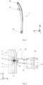
- the articulation between the first connecting rod 20 and the opening 3 is of the ball joint type.
- This articulation comprises for example a yoke 8 provided with two wings 8'.
- the yoke 8 is fixed on the opening, for example by bolting and/or riveting and/or screwing, near the edge 4, for example near the rebate 4'.
- This articulation comprises for example a rod 21 provided with an orifice.
- the rod 21 is threaded so as to be fixed to the connecting rod 20 by screwing two nuts 22 which pinch the first connecting rod 20.
- Such a fixing allows an adjustment between the opening 3 and the body 2 at the level of the first connecting rod 20.
- a ball joint comprising a shaft of axis A1 or substantially of axis A1, is arranged within the orifice formed in the rod 21, the shaft cooperating with the two wings of the yoke 8.
- the shaft of axis A1 then ensures a pivot connection of axis A1 relative to the yoke 8 while the ball joint releases other degrees of freedom in rotation.
- the first connecting rod 20 and/or the second connecting rod 30 comprises a means 50 for opening/closing the opening 3.
- the opening/closing means 50 comprises a motor.
- the arrangement 10 comprises two openings for the same opening 11 arranged within the body 2.
- a lateral opening 11 a lateral opening 3' is arranged at the front and opens forward while the second lateral opening, the opening 3, is arranged at the rear and opens rearward.
- the opening 11 in the body can be large, in particular in the longitudinal direction. The frequent entry and exit of passengers is then facilitated.
- the first and second connecting rods 20, 30 provide great robustness to the opening 3. Indeed, the distance or spacing, in the longitudinal direction for a side door, between the first and second axes A1 and A2, generates great rigidity. The robustness is further accentuated in the case of use of the third connecting rod 40. Indeed, this configuration makes it possible to ensure triangulation with a triangle “surface area” between the fixing points of the connecting rods, or yokes, sufficient to ensure robustness and reliability. For increased rigidity, the triangle surface area must be maximized with regard to the geometry of the opening. As a reminder, the articulation between the opening 3 and the second connecting rod 30, for example of axis A2, is distant from the articulation between the opening 3 and the first connecting rod 20, for example of axis A1.
- the interface between the first connecting rod 20 and the opening 3 is produced via a ball joint which makes it possible to introduce a degree of freedom in rotation in the transverse or substantially transverse direction Y to absorb any geometric variability of the parts and the assembly process.
- any blockage of the mechanism, or high handling forces, are reduced or even eliminated while allowing the first connecting rod 20 to partially take up the mass of the opening 3.
- the interface between the body 2 and the first connecting rod 20 comprises a shaft so as to obtain a pivot-type connection, for example with an axis A5.
- the axis A5 is preferably vertical or substantially vertical.
- the connecting rods are fixed at the level of the opening between the edges and the adjacent rebates, which makes these articulation-type fixings between the connecting rods and the opening invisible both from the inside of the passenger compartment and from the outside of the vehicle when the opening is closed.
- the aesthetics of the exterior surfaces of the opening are not impacted.
- the design of the vehicle is therefore not called into question by the arrangement 10 using connecting rods.
- This solution does not prevent sealing against water and/or in terms of acoustics, via simple techniques. The absence of rolling of a room on top of another avoids any noise pollution. In summary, the level of perceived quality remains high with such an arrangement 10.
- the second connecting rod 30, or lower connecting rod is fixed to the opening 3 in the lower transition zone of the opening, between the outer cutout or lower edge 6 and the inner lower rebate 6'.
- the interface of the second connecting rod 30 with the opening 3 comprises a shaft, for example so as to produce a pivot connection of axis A2 or substantially axis A2 with the opening 3.
- the second connecting rod 30 is sized to carry the majority of the mass of the opening 3.
- the interface of the second connecting rod 30 with the body 2 comprises a shaft, for example so as to produce a pivot connection of axis A4 or substantially axis A4 with the body 2.
- the first connecting rod 20, or central connecting rod due to its placement in the median zone M in the vertical direction, is fixed to the opening 3 in the transition zone of the rear vertical edge 4 of the rear opening 3, between the rear exterior cutout 4 and the rear interior rebate 4'.
- the interface of the first connecting rod 20 with the opening 3 comprises a ball joint.
- the interface of the first connecting rod 20 with the body 2 is arranged at the level of a side of the rear body 12, behind the opening 3 when it is in the closed position, as illustrated in the Figures 1 and 2 . From the outside, in the closed position of the opening, the first connecting rod 20, and possibly its articulation on the side of the body 12, remain visible. It is possible to envisage a means of concealment, such as an articulated hatch, intended to come flush with the body to close a body housing in which the first connecting rod 20 is positioned.
- the upper connecting rod 40 and the lower connecting rod 30 have parallel and collinear pivot axes, both with respect to the opening and with respect to the body.
- the second connecting rod 30 and the third connecting rod 40 have identical, or substantially identical, center distances and generate identical, or substantially identical, angles relative to the opening 3 and/or the opening 11 in the body 2.
- the first connecting rod 20, or central connecting rod then has a center distance and pivot angles slightly different from the second and third connecting rods 30, 40.
- the geometry may be of the parallelogram type.
- the second and third connecting rods 30, 40 do not hinder access to or exit from the passenger compartment 9.
- the first connecting rod 20 being arranged on the movement side, in other words at the rear for a rear side door 3 opening towards the rear and at the front for a front side door 3' opening towards the front, the first connecting rod 20 also does not hinder access to or exit from the passenger compartment 9.
- the shape of the connecting rods can be specific.
- the articulation between the first connecting rod and the body and the articulation between the first connecting rod and the opening are offset by a value E in the vertical direction.
- This offset associated with the first connecting rod 20 “off-center” in the vertical direction, facilitates compatibility with the exterior styling shapes and lines of the vehicle.
- the first connecting rod 20 also supports the mass of the opening 3.
- its section has smaller dimensions compared to the dimensions of the section of the second connecting rod 30.
- an upper connecting rod or third connecting rod 40 is fixed to the opening 3 in the upper transition zone of the opening, between the upper exterior cutout 7 and the upper interior rebate 7'.
- this third connecting rod only provides a guiding function. It does not take up much or any force due to the mass of the opening.
- This arrangement comprising three connecting rods for the same door is particularly robust, which makes it reliable over time, despite a significant number of usage cycles over the lifetime of the shared-type vehicle. Due to the absence of bearings, both opening and closing are particularly silent. The joints between the connecting rods and the opening being between the door edges and the adjacent rebates, the connecting rods are invisible to the passengers seated inside the passenger compartment 9 once the opening 3 is in the closed position ( figure 2 ).
- the opening/closing means 50 makes it possible to automate the opening of the door by applying a torque to the first connecting rod 20.
- a motor and possibly a suitable transmission are mounted at the interface between the body 2 and the connecting rod 20, for example on a suitable yoke 23 illustrated in the figure. figure 4 .
- the motor can, for example, create a torque around, or substantially around, the A5 axis.
- the variant of the embodiment comprises an opening 11 obstructed by two openings, the rear opening 3 opening towards the rear, and the front opening 3' opening forward.
- These two openings are “swinging" doors, in other words pivoting around vertical or substantially vertical axes, offering welcoming kinematics for users of the vehicle.
- the opening/closing principle for the front door 3' is similar to the opening/closing principle for the rear door 3.
- the front and rear doors 3, 3' open and close simultaneously, or substantially simultaneously.
- such kinematics do not encroach, or only slightly, on the opening 11, which provides excellent accessibility within the passenger compartment 9 of the motor vehicle 1.
- This arrangement is particularly simple since it only requires shafts or axles and preferably at least one ball joint for the joints. As mentioned above, the arrangement is particularly robust, which makes it reliable and durable.
- the large triangulation obtained by the three connecting rods provides excellent stability during opening and closing operations of the opening leaf.
- operating clearances at the level of the pivot connection shafts or axles and/or the ball joint type connections are small in order to increase the stability and precision of operation.
- Only the first and second connecting rods preferably ensure the absorption of the mass of the opening leaf.
- the upper connecting rod 40 preferably ensures the absorption of forces in the longitudinal direction X or substantially in this direction and in the transverse direction Y or substantially in this direction, in particular according to the opening position of the opening leaf.
- the third connecting rod 40 does not absorb forces in the vertical direction Z or substantially in this direction.
- Such an arrangement offers more freedom in the design of the exterior surfaces.
- the thickness of the floor of such a vehicle is, for example, increased in order to accommodate at least one battery.
- the second connecting rod which has a large section since it takes up most of the mass of the opening, is installed on the body at the level of this floor. In other words, we take advantage of the thickness of the body at this location to arrange the second connecting rod which has a significant thickness in the vertical direction.
- the arrangement provides silence during operation, particularly due to the absence of slides and/or rolling elements.
- the first connecting rod 20 can be arranged at different locations depending on the vertical direction.
- a position rather in the upper part of the middle zone as illustrated in the figure 2 , on a side rear door type opening allows to move away from the rear wheel arch at the interface between the first connecting rod and the upper part of the body, in this case the rear body side 12.
- Such positioning in the case of a front side door type opening, allows to move away from the engine compartment at the interface between the first connecting rod and the upper part of the front body, in this case a front body side for example.
- the location of the first connecting rod can be chosen according to the aesthetics of the vehicle.
- this axis distance extends in the transverse direction or substantially in this direction.
- the vehicle may comprise only one arrangement comprising a single opening, for example a side door on the right or on the left, or yet another arrangement with a side door on each side of the vehicle, i.e. a side door on the right and a side door on the left.
- the vehicle is equipped with an arrangement comprising two openings on the same side or with an arrangement comprising two openings 3, 3' on both the right and the left as illustrated in the figure 7 .
- first connecting rod In the case of an arrangement comprising only one opening leaf per vehicle side, only the first connecting rod is visible in the closed position of the opening leaf.
- first connecting rod of the front side door and the first connecting rod of the rear side door are visible in the closed position of the opening leaves.
- a single side door may be preferable per vehicle side from an aesthetic point of view.
- a cover may be used in order to hide the first connecting rod when the associated door is in the closed position.
- a single-door layout is simpler in terms of sealing management than a layout comprising two doors.
- a single door avoids having to manage the possibility of a side impact between the two adjacent doors.
- a single motor is sufficient to drive the opening and closing of the single opening, which is particularly economical, especially since a lock can be removed.
- the rear edge of the door in the open position may, for example, protrude beyond the rear end of the vehicle.
Landscapes
- Engineering & Computer Science (AREA)
- Mechanical Engineering (AREA)
- Power-Operated Mechanisms For Wings (AREA)
- Body Structure For Vehicles (AREA)
- Superstructure Of Vehicle (AREA)
Claims (10)
- Anordnung (10), welche umfasst:- eine Karosserie (2) eines Fahrzeugs, insbesondere eines Kraftfahrzeugs (1),- ein Öffnungselement (3), das einen ersten Rand (4) und einen zweiten Rand (5), die vertikal oder im Wesentlichen vertikal sind, umfasst, insbesondere einen hinten angeordneten ersten Rand (4) für ein seitliches Öffnungselement, das sich nach hinten öffnet, oder einen vorn angeordneten ersten Rand (4) für ein seitliches Öffnungselement, das sich nach vorn öffnet,- mindestens eine erste Schubstange (20) und eine zweite Schubstange (30), die jeweils einerseits am Öffnungselement (3) und andererseits an der Karosserie (2) angelenkt sind, um das Öffnen und das Schließen des Öffnungselements (3) bezüglich der Karosserie (2) zu ermöglichen,wobei die erste Schubstange (20) am Öffnungselement (3) in der Nähe des ersten Randes (4) um eine erste Achse (A1) oder im Wesentlichen um eine erste Achse (A1) schwenkt, insbesondere eine vertikale oder im Wesentlichen vertikale erste Achse (A1),dadurch gekennzeichnet, dass die Anordnung (10) eine dritte Schubstange (40) umfasst, die am Öffnungselement (3), insbesondere in der Nähe des zweiten Randes (5) des Öffnungselements (3), um eine dritte Achse (A3) oder im Wesentlichen um eine dritte Achse (A3) schwenkbar ist,
unddadurch, dass die zweite Schubstange (30) zwischen einem unteren Rand (6) des Öffnungselements (3) und einem unteren inneren Falz (6') des Öffnungselements (3) angeordnet ist, und/oder dadurch, dass die dritte Schubstange (40) zwischen einem oberen Rand (7) des Öffnungselements (3) und einem oberen inneren Falz (7') des Öffnungselements (3) angeordnet ist, so dass sie weder vom Inneren noch von außerhalb eines solchen Fahrzeugs (1) sichtbar ist, wenn sich das Öffnungselement (3) in einer geschlossenen Position befindet. - Anordnung (10) nach dem vorhergehenden Anspruch, dadurch gekennzeichnet, dass die zweite Schubstange (30) am Öffnungselement (3) in der Nähe des zweiten Randes (5) um eine zweite Achse (A2) oder im Wesentlichen um eine zweite Achse (A2) schwenkt, insbesondere eine vertikale oder im Wesentlichen vertikale zweite Achse (A2).
- Anordnung (10) nach dem vorhergehenden Anspruch, dadurch gekennzeichnet, dass die erste Achse (A1) und die zweite Achse (A2) versetzt sind, insbesondere in der Längsrichtung (X).
- Anordnung (10) nach einem der vorhergehenden Ansprüche, dadurch gekennzeichnet, dass die zweite Schubstange (30) in der vertikalen Richtung (Z) unten am Öffnungselement (3) und an der Karosserie (2) angeordnet ist, und/oder dadurch, dass die erste Schubstange (20) in der vertikalen Richtung (Z) in einem mittleren Bereich (M) des Öffnungselements (3) und der Karosserie (2) angeordnet ist.
- Anordnung (10) nach einem der vorhergehenden Ansprüche, dadurch gekennzeichnet, dass die dritte Schubstange (40) in der vertikalen Richtung (Z) oben am Öffnungselement (3) und an der Karosserie (2) angeordnet ist.
- Anordnung (10) nach einem der vorhergehenden Ansprüche, dadurch gekennzeichnet, dass die zweite Achse (A2) und die dritte Achse (A3) zusammenfallen oder im Wesentlichen zusammenfallen.
- Anordnung (10) nach einem der vorhergehenden Ansprüche, dadurch gekennzeichnet, dass das Gelenk zwischen der ersten Schubstange (20) und dem Öffnungselement (3) von Typ eines Kugelgelenks ist.
- Anordnung (10) nach einem der vorhergehenden Ansprüche, dadurch gekennzeichnet, dass die erste Schubstange (20) und/oder die zweite Schubstange (30) ein Mittel zum Öffnen / Schließen (50) des Öffnungselements (3) umfasst, insbesondere ein Mittel zum Öffnen / Schließen (50), das einen Motor umfasst.
- Anordnung (10) nach einem der vorhergehenden Ansprüche, dadurch gekennzeichnet, dass die Anordnung (10) zwei Öffnungselemente (3) für ein und dieselbe Öffnung (11), die innerhalb der Karosserie (2) ausgebildet ist, umfasst, insbesondere ein vorderes seitliches Öffnungselement, das sich nach vorn öffnet, und ein hinteres seitliches Öffnungselement, das sich nach hinten öffnet.
- Fahrzeug, insbesondere Kraftfahrzeug (1), dadurch gekennzeichnet, dass es eine Anordnung (10) nach einem der vorhergehenden Ansprüche umfasst.
Applications Claiming Priority (1)
| Application Number | Priority Date | Filing Date | Title |
|---|---|---|---|
| FR1906253A FR3097249B1 (fr) | 2019-06-12 | 2019-06-12 | Agencement d’un ouvrant sur une caisse de véhicule. |
Publications (2)
| Publication Number | Publication Date |
|---|---|
| EP3751085A1 EP3751085A1 (de) | 2020-12-16 |
| EP3751085B1 true EP3751085B1 (de) | 2024-11-13 |
Family
ID=68138408
Family Applications (1)
| Application Number | Title | Priority Date | Filing Date |
|---|---|---|---|
| EP20178437.8A Active EP3751085B1 (de) | 2019-06-12 | 2020-06-05 | Anordnung eines öffnungselements auf einer fahrzeugkarosserie |
Country Status (2)
| Country | Link |
|---|---|
| EP (1) | EP3751085B1 (de) |
| FR (1) | FR3097249B1 (de) |
Families Citing this family (1)
| Publication number | Priority date | Publication date | Assignee | Title |
|---|---|---|---|---|
| CN115573625B (zh) * | 2022-10-09 | 2025-06-27 | 中国航空工业集团公司西安飞机设计研究所 | 一种飞机舱门锁机构 |
Family Cites Families (6)
| Publication number | Priority date | Publication date | Assignee | Title |
|---|---|---|---|---|
| JPS59179181U (ja) * | 1983-05-19 | 1984-11-30 | トヨタ自動車株式会社 | 自動車の可動フエンダ−部泥よけ構造 |
| FR2734208B1 (fr) * | 1995-05-17 | 1997-08-01 | Peugeot | Agencement d'une porte laterale sur un vehicule automobile |
| FR2746059B1 (fr) * | 1996-03-18 | 1998-04-24 | Porte laterale de vehicule automobile a cinematique d'ouverture perfectionnee | |
| US6382705B1 (en) * | 2001-02-01 | 2002-05-07 | General Motors Corporation | Vehicle independent rear access panel with four bar hinge |
| JP2003154849A (ja) * | 2001-11-21 | 2003-05-27 | Fuji Heavy Ind Ltd | せり出しドアヒンジ構造 |
| FR3041315B1 (fr) * | 2015-09-17 | 2018-09-14 | Faurecia Bloc Avant | Systeme d'ouverture de hayon a deux bielettes |
-
2019
- 2019-06-12 FR FR1906253A patent/FR3097249B1/fr active Active
-
2020
- 2020-06-05 EP EP20178437.8A patent/EP3751085B1/de active Active
Also Published As
| Publication number | Publication date |
|---|---|
| FR3097249B1 (fr) | 2021-06-11 |
| FR3097249A1 (fr) | 2020-12-18 |
| EP3751085A1 (de) | 2020-12-16 |
Similar Documents
| Publication | Publication Date | Title |
|---|---|---|
| FR2983826A1 (fr) | Structure avant d'avion perfectionnee a compartiment pour train d'atterrissage. | |
| EP1706284B1 (de) | Schliessvorrichtung für ein mit einer luke und einem sonnendach versehenes fahrzeug | |
| EP2989004A1 (de) | System zum öffnen und schliessen eines fahrwerkschachtes | |
| EP3751085B1 (de) | Anordnung eines öffnungselements auf einer fahrzeugkarosserie | |
| EP1412213B1 (de) | Kabriolett mit versenkbarem dach | |
| EP2110277B1 (de) | Kraftfahrzeug mit vier Rädern, drei Sitze und seitliche Schiebetüre | |
| EP3626610B1 (de) | Vorderes fahrwerksmodul für luftfahrzeug | |
| EP1234702A1 (de) | Kombi-Kraftfahrzeug mit einem variablen Dach/Heckbereich | |
| FR3048202A1 (fr) | Vehicule a porte a ouverture a faible encombrement | |
| EP1612076A1 (de) | Steuervorrichtung zum Kippen eines bewegbaren Dach und entsprechendes Fahrzeug | |
| EP1706283B1 (de) | Ein sonnendach und eine luke umfassendes fahrzeug | |
| EP1741617A2 (de) | Fahrzeug mit verstärkter Karrosserie | |
| FR2873088A1 (fr) | Structure de base de vehicule a plusieurs toits rapportes et vehicules correspondants | |
| FR3059609B1 (fr) | Dispositif d'articulation d'une porte laterale de vehicule | |
| FR3148937A1 (fr) | Ensemble de vitres latérales pour véhicule automobile | |
| FR2919529A1 (fr) | Porte de vehicule automobile a vitre escamotable | |
| EP2770292A1 (de) | Gepanzertes Fahrzeug mit kippbarer Zugangsrampe | |
| FR3162195A1 (fr) | Pièce de renfort pour une partie structurelle latérale arrière d’un véhicule automobile | |
| EP4360926A1 (de) | Zugangsvorrichtung mit einer tür in ellytre | |
| EP4634008A1 (de) | Heckklappenverkleidung für kraftfahrzeug | |
| WO2015040341A1 (fr) | Porte allegee a structure renforcee | |
| FR2996500A1 (fr) | Carrosserie de vehicule avec pavillon arriere de toit coulissant. | |
| EP2631159B1 (de) | Karosserierstruktursystem eines Fahrzeugs vom Typ mit offenem Verdeck | |
| FR2885324A1 (fr) | Vehicule du type cabriolet a toit rigide avec custodes | |
| FR2885325A1 (fr) | Vehicule du type cabriolet a toit rigide type targa |
Legal Events
| Date | Code | Title | Description |
|---|---|---|---|
| PUAI | Public reference made under article 153(3) epc to a published international application that has entered the european phase |
Free format text: ORIGINAL CODE: 0009012 |
|
| STAA | Information on the status of an ep patent application or granted ep patent |
Free format text: STATUS: THE APPLICATION HAS BEEN PUBLISHED |
|
| AK | Designated contracting states |
Kind code of ref document: A1 Designated state(s): AL AT BE BG CH CY CZ DE DK EE ES FI FR GB GR HR HU IE IS IT LI LT LU LV MC MK MT NL NO PL PT RO RS SE SI SK SM TR |
|
| AX | Request for extension of the european patent |
Extension state: BA ME |
|
| STAA | Information on the status of an ep patent application or granted ep patent |
Free format text: STATUS: REQUEST FOR EXAMINATION WAS MADE |
|
| 17P | Request for examination filed |
Effective date: 20210616 |
|
| RBV | Designated contracting states (corrected) |
Designated state(s): AL AT BE BG CH CY CZ DE DK EE ES FI FR GB GR HR HU IE IS IT LI LT LU LV MC MK MT NL NO PL PT RO RS SE SI SK SM TR |
|
| RAP3 | Party data changed (applicant data changed or rights of an application transferred) |
Owner name: RENAULT S.A.S |
|
| RAP3 | Party data changed (applicant data changed or rights of an application transferred) |
Owner name: RENAULT S.A.S |
|
| P01 | Opt-out of the competence of the unified patent court (upc) registered |
Effective date: 20230608 |
|
| GRAP | Despatch of communication of intention to grant a patent |
Free format text: ORIGINAL CODE: EPIDOSNIGR1 |
|
| STAA | Information on the status of an ep patent application or granted ep patent |
Free format text: STATUS: GRANT OF PATENT IS INTENDED |
|
| INTG | Intention to grant announced |
Effective date: 20240606 |
|
| GRAS | Grant fee paid |
Free format text: ORIGINAL CODE: EPIDOSNIGR3 |
|
| GRAA | (expected) grant |
Free format text: ORIGINAL CODE: 0009210 |
|
| STAA | Information on the status of an ep patent application or granted ep patent |
Free format text: STATUS: THE PATENT HAS BEEN GRANTED |
|
| AK | Designated contracting states |
Kind code of ref document: B1 Designated state(s): AL AT BE BG CH CY CZ DE DK EE ES FI FR GB GR HR HU IE IS IT LI LT LU LV MC MK MT NL NO PL PT RO RS SE SI SK SM TR |
|
| REG | Reference to a national code |
Ref country code: GB Ref legal event code: FG4D Free format text: NOT ENGLISH |
|
| REG | Reference to a national code |
Ref country code: CH Ref legal event code: EP |
|
| REG | Reference to a national code |
Ref country code: IE Ref legal event code: FG4D Free format text: LANGUAGE OF EP DOCUMENT: FRENCH |
|
| REG | Reference to a national code |
Ref country code: DE Ref legal event code: R096 Ref document number: 602020041184 Country of ref document: DE |
|
| REG | Reference to a national code |
Ref country code: LT Ref legal event code: MG9D |
|
| REG | Reference to a national code |
Ref country code: NL Ref legal event code: MP Effective date: 20241113 |
|
| PG25 | Lapsed in a contracting state [announced via postgrant information from national office to epo] |
Ref country code: PT Free format text: LAPSE BECAUSE OF FAILURE TO SUBMIT A TRANSLATION OF THE DESCRIPTION OR TO PAY THE FEE WITHIN THE PRESCRIBED TIME-LIMIT Effective date: 20250313 Ref country code: HR Free format text: LAPSE BECAUSE OF FAILURE TO SUBMIT A TRANSLATION OF THE DESCRIPTION OR TO PAY THE FEE WITHIN THE PRESCRIBED TIME-LIMIT Effective date: 20241113 Ref country code: IS Free format text: LAPSE BECAUSE OF FAILURE TO SUBMIT A TRANSLATION OF THE DESCRIPTION OR TO PAY THE FEE WITHIN THE PRESCRIBED TIME-LIMIT Effective date: 20250313 |
|
| PG25 | Lapsed in a contracting state [announced via postgrant information from national office to epo] |
Ref country code: NL Free format text: LAPSE BECAUSE OF FAILURE TO SUBMIT A TRANSLATION OF THE DESCRIPTION OR TO PAY THE FEE WITHIN THE PRESCRIBED TIME-LIMIT Effective date: 20241113 Ref country code: FI Free format text: LAPSE BECAUSE OF FAILURE TO SUBMIT A TRANSLATION OF THE DESCRIPTION OR TO PAY THE FEE WITHIN THE PRESCRIBED TIME-LIMIT Effective date: 20241113 |
|
| REG | Reference to a national code |
Ref country code: AT Ref legal event code: MK05 Ref document number: 1741808 Country of ref document: AT Kind code of ref document: T Effective date: 20241113 |
|
| PG25 | Lapsed in a contracting state [announced via postgrant information from national office to epo] |
Ref country code: BG Free format text: LAPSE BECAUSE OF FAILURE TO SUBMIT A TRANSLATION OF THE DESCRIPTION OR TO PAY THE FEE WITHIN THE PRESCRIBED TIME-LIMIT Effective date: 20241113 |
|
| PG25 | Lapsed in a contracting state [announced via postgrant information from national office to epo] |
Ref country code: ES Free format text: LAPSE BECAUSE OF FAILURE TO SUBMIT A TRANSLATION OF THE DESCRIPTION OR TO PAY THE FEE WITHIN THE PRESCRIBED TIME-LIMIT Effective date: 20241113 |
|
| PG25 | Lapsed in a contracting state [announced via postgrant information from national office to epo] |
Ref country code: NO Free format text: LAPSE BECAUSE OF FAILURE TO SUBMIT A TRANSLATION OF THE DESCRIPTION OR TO PAY THE FEE WITHIN THE PRESCRIBED TIME-LIMIT Effective date: 20250213 |
|
| PG25 | Lapsed in a contracting state [announced via postgrant information from national office to epo] |
Ref country code: AT Free format text: LAPSE BECAUSE OF FAILURE TO SUBMIT A TRANSLATION OF THE DESCRIPTION OR TO PAY THE FEE WITHIN THE PRESCRIBED TIME-LIMIT Effective date: 20241113 Ref country code: GR Free format text: LAPSE BECAUSE OF FAILURE TO SUBMIT A TRANSLATION OF THE DESCRIPTION OR TO PAY THE FEE WITHIN THE PRESCRIBED TIME-LIMIT Effective date: 20250214 Ref country code: LV Free format text: LAPSE BECAUSE OF FAILURE TO SUBMIT A TRANSLATION OF THE DESCRIPTION OR TO PAY THE FEE WITHIN THE PRESCRIBED TIME-LIMIT Effective date: 20241113 |
|
| PG25 | Lapsed in a contracting state [announced via postgrant information from national office to epo] |
Ref country code: PL Free format text: LAPSE BECAUSE OF FAILURE TO SUBMIT A TRANSLATION OF THE DESCRIPTION OR TO PAY THE FEE WITHIN THE PRESCRIBED TIME-LIMIT Effective date: 20241113 |
|
| PG25 | Lapsed in a contracting state [announced via postgrant information from national office to epo] |
Ref country code: RS Free format text: LAPSE BECAUSE OF FAILURE TO SUBMIT A TRANSLATION OF THE DESCRIPTION OR TO PAY THE FEE WITHIN THE PRESCRIBED TIME-LIMIT Effective date: 20250213 |
|
| PG25 | Lapsed in a contracting state [announced via postgrant information from national office to epo] |
Ref country code: SM Free format text: LAPSE BECAUSE OF FAILURE TO SUBMIT A TRANSLATION OF THE DESCRIPTION OR TO PAY THE FEE WITHIN THE PRESCRIBED TIME-LIMIT Effective date: 20241113 |
|
| PGFP | Annual fee paid to national office [announced via postgrant information from national office to epo] |
Ref country code: DE Payment date: 20250618 Year of fee payment: 6 |
|
| PG25 | Lapsed in a contracting state [announced via postgrant information from national office to epo] |
Ref country code: DK Free format text: LAPSE BECAUSE OF FAILURE TO SUBMIT A TRANSLATION OF THE DESCRIPTION OR TO PAY THE FEE WITHIN THE PRESCRIBED TIME-LIMIT Effective date: 20241113 |
|
| PGFP | Annual fee paid to national office [announced via postgrant information from national office to epo] |
Ref country code: GB Payment date: 20250618 Year of fee payment: 6 |
|
| PG25 | Lapsed in a contracting state [announced via postgrant information from national office to epo] |
Ref country code: EE Free format text: LAPSE BECAUSE OF FAILURE TO SUBMIT A TRANSLATION OF THE DESCRIPTION OR TO PAY THE FEE WITHIN THE PRESCRIBED TIME-LIMIT Effective date: 20241113 |
|
| PGFP | Annual fee paid to national office [announced via postgrant information from national office to epo] |
Ref country code: FR Payment date: 20250626 Year of fee payment: 6 |
|
| PG25 | Lapsed in a contracting state [announced via postgrant information from national office to epo] |
Ref country code: RO Free format text: LAPSE BECAUSE OF FAILURE TO SUBMIT A TRANSLATION OF THE DESCRIPTION OR TO PAY THE FEE WITHIN THE PRESCRIBED TIME-LIMIT Effective date: 20241113 |
|
| PG25 | Lapsed in a contracting state [announced via postgrant information from national office to epo] |
Ref country code: SK Free format text: LAPSE BECAUSE OF FAILURE TO SUBMIT A TRANSLATION OF THE DESCRIPTION OR TO PAY THE FEE WITHIN THE PRESCRIBED TIME-LIMIT Effective date: 20241113 |
|
| PG25 | Lapsed in a contracting state [announced via postgrant information from national office to epo] |
Ref country code: CZ Free format text: LAPSE BECAUSE OF FAILURE TO SUBMIT A TRANSLATION OF THE DESCRIPTION OR TO PAY THE FEE WITHIN THE PRESCRIBED TIME-LIMIT Effective date: 20241113 |
|
| PG25 | Lapsed in a contracting state [announced via postgrant information from national office to epo] |
Ref country code: IT Free format text: LAPSE BECAUSE OF FAILURE TO SUBMIT A TRANSLATION OF THE DESCRIPTION OR TO PAY THE FEE WITHIN THE PRESCRIBED TIME-LIMIT Effective date: 20241113 |
|
| REG | Reference to a national code |
Ref country code: DE Ref legal event code: R097 Ref document number: 602020041184 Country of ref document: DE |
|
| PG25 | Lapsed in a contracting state [announced via postgrant information from national office to epo] |
Ref country code: SE Free format text: LAPSE BECAUSE OF FAILURE TO SUBMIT A TRANSLATION OF THE DESCRIPTION OR TO PAY THE FEE WITHIN THE PRESCRIBED TIME-LIMIT Effective date: 20241113 |
|
| PLBE | No opposition filed within time limit |
Free format text: ORIGINAL CODE: 0009261 |
|
| STAA | Information on the status of an ep patent application or granted ep patent |
Free format text: STATUS: NO OPPOSITION FILED WITHIN TIME LIMIT |
|
| 26N | No opposition filed |
Effective date: 20250814 |
|
| REG | Reference to a national code |
Ref country code: CH Ref legal event code: H13 Free format text: ST27 STATUS EVENT CODE: U-0-0-H10-H13 (AS PROVIDED BY THE NATIONAL OFFICE) Effective date: 20260127 |
|
| PG25 | Lapsed in a contracting state [announced via postgrant information from national office to epo] |
Ref country code: MC Free format text: LAPSE BECAUSE OF FAILURE TO SUBMIT A TRANSLATION OF THE DESCRIPTION OR TO PAY THE FEE WITHIN THE PRESCRIBED TIME-LIMIT Effective date: 20241113 |