EP3750574B1 - Liquid transfer system and components for same - Google Patents
Liquid transfer system and components for same Download PDFInfo
- Publication number
- EP3750574B1 EP3750574B1 EP19180089.5A EP19180089A EP3750574B1 EP 3750574 B1 EP3750574 B1 EP 3750574B1 EP 19180089 A EP19180089 A EP 19180089A EP 3750574 B1 EP3750574 B1 EP 3750574B1
- Authority
- EP
- European Patent Office
- Prior art keywords
- needle
- syringe
- container
- connecting component
- connection
- Prior art date
- Legal status (The legal status is an assumption and is not a legal conclusion. Google has not performed a legal analysis and makes no representation as to the accuracy of the status listed.)
- Active
Links
- 239000007788 liquid Substances 0.000 title claims description 49
- 239000000126 substance Substances 0.000 claims description 19
- 238000007789 sealing Methods 0.000 claims description 14
- 239000004743 Polypropylene Substances 0.000 claims description 4
- -1 polypropylene Polymers 0.000 claims description 2
- 229920001155 polypropylene Polymers 0.000 claims description 2
- 229940126601 medicinal product Drugs 0.000 claims 4
- 229940079593 drug Drugs 0.000 description 29
- 239000003814 drug Substances 0.000 description 28
- 239000007789 gas Substances 0.000 description 21
- 238000001802 infusion Methods 0.000 description 21
- 239000012530 fluid Substances 0.000 description 13
- 238000001990 intravenous administration Methods 0.000 description 13
- 239000004480 active ingredient Substances 0.000 description 10
- 239000000443 aerosol Substances 0.000 description 8
- 239000000463 material Substances 0.000 description 8
- 238000002483 medication Methods 0.000 description 6
- 229920002725 thermoplastic elastomer Polymers 0.000 description 4
- 239000003978 infusion fluid Substances 0.000 description 3
- 238000002347 injection Methods 0.000 description 3
- 239000007924 injection Substances 0.000 description 3
- 238000010521 absorption reaction Methods 0.000 description 2
- 238000011109 contamination Methods 0.000 description 2
- 230000000694 effects Effects 0.000 description 2
- 230000036541 health Effects 0.000 description 2
- 206010028980 Neoplasm Diseases 0.000 description 1
- 208000036142 Viral infection Diseases 0.000 description 1
- 230000001154 acute effect Effects 0.000 description 1
- XAGFODPZIPBFFR-UHFFFAOYSA-N aluminium Chemical compound [Al] XAGFODPZIPBFFR-UHFFFAOYSA-N 0.000 description 1
- 229910052782 aluminium Inorganic materials 0.000 description 1
- 239000003242 anti bacterial agent Substances 0.000 description 1
- 229940088710 antibiotic agent Drugs 0.000 description 1
- 239000003443 antiviral agent Substances 0.000 description 1
- 230000004888 barrier function Effects 0.000 description 1
- 239000008280 blood Substances 0.000 description 1
- 210000004369 blood Anatomy 0.000 description 1
- 201000011510 cancer Diseases 0.000 description 1
- 238000001311 chemical methods and process Methods 0.000 description 1
- 239000000306 component Substances 0.000 description 1
- 230000006835 compression Effects 0.000 description 1
- 238000007906 compression Methods 0.000 description 1
- 239000000356 contaminant Substances 0.000 description 1
- 231100000599 cytotoxic agent Toxicity 0.000 description 1
- 239000002619 cytotoxin Substances 0.000 description 1
- 230000006735 deficit Effects 0.000 description 1
- 239000013013 elastic material Substances 0.000 description 1
- 238000005538 encapsulation Methods 0.000 description 1
- 230000007717 exclusion Effects 0.000 description 1
- 230000002349 favourable effect Effects 0.000 description 1
- 230000002068 genetic effect Effects 0.000 description 1
- 230000008376 long-term health Effects 0.000 description 1
- 210000004072 lung Anatomy 0.000 description 1
- 238000000034 method Methods 0.000 description 1
- 238000010327 methods by industry Methods 0.000 description 1
- 230000001681 protective effect Effects 0.000 description 1
- 229940121896 radiopharmaceutical Drugs 0.000 description 1
- 239000012217 radiopharmaceutical Substances 0.000 description 1
- 230000002799 radiopharmaceutical effect Effects 0.000 description 1
- 239000002904 solvent Substances 0.000 description 1
- 230000000087 stabilizing effect Effects 0.000 description 1
- 238000002560 therapeutic procedure Methods 0.000 description 1
- 231100000331 toxic Toxicity 0.000 description 1
- 230000002588 toxic effect Effects 0.000 description 1
- 238000011282 treatment Methods 0.000 description 1
- 230000009385 viral infection Effects 0.000 description 1
Images


Classifications
-
- A—HUMAN NECESSITIES
- A61—MEDICAL OR VETERINARY SCIENCE; HYGIENE
- A61J—CONTAINERS SPECIALLY ADAPTED FOR MEDICAL OR PHARMACEUTICAL PURPOSES; DEVICES OR METHODS SPECIALLY ADAPTED FOR BRINGING PHARMACEUTICAL PRODUCTS INTO PARTICULAR PHYSICAL OR ADMINISTERING FORMS; DEVICES FOR ADMINISTERING FOOD OR MEDICINES ORALLY; BABY COMFORTERS; DEVICES FOR RECEIVING SPITTLE
- A61J1/00—Containers specially adapted for medical or pharmaceutical purposes
- A61J1/14—Details; Accessories therefor
- A61J1/20—Arrangements for transferring or mixing fluids, e.g. from vial to syringe
- A61J1/2096—Combination of a vial and a syringe for transferring or mixing their contents
-
- A—HUMAN NECESSITIES
- A61—MEDICAL OR VETERINARY SCIENCE; HYGIENE
- A61M—DEVICES FOR INTRODUCING MEDIA INTO, OR ONTO, THE BODY; DEVICES FOR TRANSDUCING BODY MEDIA OR FOR TAKING MEDIA FROM THE BODY; DEVICES FOR PRODUCING OR ENDING SLEEP OR STUPOR
- A61M5/00—Devices for bringing media into the body in a subcutaneous, intra-vascular or intramuscular way; Accessories therefor, e.g. filling or cleaning devices, arm-rests
- A61M5/14—Infusion devices, e.g. infusing by gravity; Blood infusion; Accessories therefor
- A61M5/162—Needle sets, i.e. connections by puncture between reservoir and tube ; Connections between reservoir and tube
-
- A—HUMAN NECESSITIES
- A61—MEDICAL OR VETERINARY SCIENCE; HYGIENE
- A61J—CONTAINERS SPECIALLY ADAPTED FOR MEDICAL OR PHARMACEUTICAL PURPOSES; DEVICES OR METHODS SPECIALLY ADAPTED FOR BRINGING PHARMACEUTICAL PRODUCTS INTO PARTICULAR PHYSICAL OR ADMINISTERING FORMS; DEVICES FOR ADMINISTERING FOOD OR MEDICINES ORALLY; BABY COMFORTERS; DEVICES FOR RECEIVING SPITTLE
- A61J1/00—Containers specially adapted for medical or pharmaceutical purposes
- A61J1/14—Details; Accessories therefor
- A61J1/1412—Containers with closing means, e.g. caps
- A61J1/1418—Threaded type
-
- A—HUMAN NECESSITIES
- A61—MEDICAL OR VETERINARY SCIENCE; HYGIENE
- A61J—CONTAINERS SPECIALLY ADAPTED FOR MEDICAL OR PHARMACEUTICAL PURPOSES; DEVICES OR METHODS SPECIALLY ADAPTED FOR BRINGING PHARMACEUTICAL PRODUCTS INTO PARTICULAR PHYSICAL OR ADMINISTERING FORMS; DEVICES FOR ADMINISTERING FOOD OR MEDICINES ORALLY; BABY COMFORTERS; DEVICES FOR RECEIVING SPITTLE
- A61J1/00—Containers specially adapted for medical or pharmaceutical purposes
- A61J1/14—Details; Accessories therefor
- A61J1/18—Arrangements for indicating condition of container contents, e.g. sterile condition
-
- A—HUMAN NECESSITIES
- A61—MEDICAL OR VETERINARY SCIENCE; HYGIENE
- A61J—CONTAINERS SPECIALLY ADAPTED FOR MEDICAL OR PHARMACEUTICAL PURPOSES; DEVICES OR METHODS SPECIALLY ADAPTED FOR BRINGING PHARMACEUTICAL PRODUCTS INTO PARTICULAR PHYSICAL OR ADMINISTERING FORMS; DEVICES FOR ADMINISTERING FOOD OR MEDICINES ORALLY; BABY COMFORTERS; DEVICES FOR RECEIVING SPITTLE
- A61J1/00—Containers specially adapted for medical or pharmaceutical purposes
- A61J1/14—Details; Accessories therefor
- A61J1/20—Arrangements for transferring or mixing fluids, e.g. from vial to syringe
- A61J1/2003—Accessories used in combination with means for transfer or mixing of fluids, e.g. for activating fluid flow, separating fluids, filtering fluid or venting
- A61J1/2048—Connecting means
-
- A—HUMAN NECESSITIES
- A61—MEDICAL OR VETERINARY SCIENCE; HYGIENE
- A61J—CONTAINERS SPECIALLY ADAPTED FOR MEDICAL OR PHARMACEUTICAL PURPOSES; DEVICES OR METHODS SPECIALLY ADAPTED FOR BRINGING PHARMACEUTICAL PRODUCTS INTO PARTICULAR PHYSICAL OR ADMINISTERING FORMS; DEVICES FOR ADMINISTERING FOOD OR MEDICINES ORALLY; BABY COMFORTERS; DEVICES FOR RECEIVING SPITTLE
- A61J1/00—Containers specially adapted for medical or pharmaceutical purposes
- A61J1/05—Containers specially adapted for medical or pharmaceutical purposes for collecting, storing or administering blood, plasma or medical fluids ; Infusion or perfusion containers
- A61J1/10—Bag-type containers
-
- A—HUMAN NECESSITIES
- A61—MEDICAL OR VETERINARY SCIENCE; HYGIENE
- A61J—CONTAINERS SPECIALLY ADAPTED FOR MEDICAL OR PHARMACEUTICAL PURPOSES; DEVICES OR METHODS SPECIALLY ADAPTED FOR BRINGING PHARMACEUTICAL PRODUCTS INTO PARTICULAR PHYSICAL OR ADMINISTERING FORMS; DEVICES FOR ADMINISTERING FOOD OR MEDICINES ORALLY; BABY COMFORTERS; DEVICES FOR RECEIVING SPITTLE
- A61J1/00—Containers specially adapted for medical or pharmaceutical purposes
- A61J1/14—Details; Accessories therefor
- A61J1/20—Arrangements for transferring or mixing fluids, e.g. from vial to syringe
- A61J1/2003—Accessories used in combination with means for transfer or mixing of fluids, e.g. for activating fluid flow, separating fluids, filtering fluid or venting
- A61J1/2006—Piercing means
- A61J1/2013—Piercing means having two piercing ends
-
- A—HUMAN NECESSITIES
- A61—MEDICAL OR VETERINARY SCIENCE; HYGIENE
- A61J—CONTAINERS SPECIALLY ADAPTED FOR MEDICAL OR PHARMACEUTICAL PURPOSES; DEVICES OR METHODS SPECIALLY ADAPTED FOR BRINGING PHARMACEUTICAL PRODUCTS INTO PARTICULAR PHYSICAL OR ADMINISTERING FORMS; DEVICES FOR ADMINISTERING FOOD OR MEDICINES ORALLY; BABY COMFORTERS; DEVICES FOR RECEIVING SPITTLE
- A61J1/00—Containers specially adapted for medical or pharmaceutical purposes
- A61J1/14—Details; Accessories therefor
- A61J1/20—Arrangements for transferring or mixing fluids, e.g. from vial to syringe
- A61J1/2003—Accessories used in combination with means for transfer or mixing of fluids, e.g. for activating fluid flow, separating fluids, filtering fluid or venting
- A61J1/2068—Venting means
- A61J1/2072—Venting means for internal venting
Definitions
- the invention relates to a liquid transfer system for transferring medical substances or drugs. It further relates to components and components of such a transfer system, in particular its connecting components and the components equipped with such connecting components, such as syringes, containers (vials) or application systems.
- Modern medical procedures or therapies may use medications or substances that are actually toxic or otherwise harmful or dangerous. Personnel involved in the handling of such substances, such as pharmacists and nurses, may therefore pose acute and long-term health risks, particularly if they are repeatedly exposed to medications or solvents released into the air during preparation, administration of medications and other similar treatments could escape. This problem can be particularly serious when cytotoxins, antiviral drugs, antibiotics or radiopharmaceuticals are involved. The health risks potentially arising from exposure to these drugs include increased risk of cancer, genetic changes, and the like. Furthermore, taking samples or blood in the event of viral infections or the like can also pose an increased risk for the handling staff.
- Such liquid transfer systems typically include a first connection component or a first adapter for connection to a first fluid container, such as a syringe, and a second connection component or a second adapter for connection to a drug container, a vial, a second syringe or an intravenous line, which includes a Provides fluid access to the patient's circulation.
- the doctor or the person treating the patient can, for example, connect a syringe to a vial via the syringe adapter and the associated vial adapter and suck the medication contained therein into the syringe.
- the adapters are then separated, and the syringe is connected to an intravenous line or access via the syringe adapter and an associated line adapter so that the medication in the syringe can be administered to the patient.
- Such a liquid transfer system including the necessary components such as connection adapters and the like is, for example, from WO2016199133A1 (or from the WO2016042544 ) known.
- the invention is based on the object of specifying a liquid transfer system for the transfer of medical substances or drugs of the type mentioned above, including its essential components such as in particular the connecting components, with which the unintentional delivery or release of active ingredient components or gases or aerosols is particularly easy to handle is particularly reliably avoided.
- a needle system comprising a number of hollow needles, arranged in a tubular connecting piece surrounded by a flange jacket, and with a distal tip(s) arranged within the connecting piece ( n) the elastic needle cap sealingly surrounding the or each needle of the needle system in the unloaded state, the flange jacket being rotatable around the needle system and around the needle cap surrounding it and being provided with a thread for connection to a second connecting component.
- the invention is based on the idea that for a safe and loss-free transfer of liquid between the syringe and another container, for example a vial, there is a stable and sealing connection between the respective ones Connection components are particularly important.
- a suitable seal must be provided on the boundary or contact surfaces of both connection components, and on the other hand, a suitable frictional connection between the connection components should be provided, on the one hand for the purpose of mechanically stabilizing the components relative to one another and, on the other hand, for the purpose of improving the sealing effect by pressing, getting produced.
- an interlocking or locking of the connecting components is provided for this purpose, with suitably positioned swivel arms causing the components to lock.
- a screw connection of the connecting components to one another is now provided, whereby the holding force between the connecting elements can be modified and adjusted as required by suitable actuation of the screw connection.
- a needle cap made of comparatively soft, elastic material is provided as a seal and sealing closure for the hollow needles provided as actual transfer channels in the connecting component. This is deformed and pushed back when it comes into contact with the other connecting element, so that the hollow needles located inside pierce it and are thus exposed to the outside in order to produce the media-side connection.
- the deformation of the needle cap can be different, so that the sealing effect provided by the needle cap and its contact with the counter surface can be suitably optimized.
- the needle cap returns to its original shape due to the elasticity of its base material and thus encloses the needle tips again, so that a reliable covering and sealing of the interior of the syringe, including the needle outlets, is guaranteed even after the transfer has been completed .
- the needle cap is particularly preferably a material with very good resistance to compression deformation and particularly good pressure relaxation properties executed.
- a thermoplastic elastomer (TPE) is particularly preferred for this purpose.
- a spring element is arranged within the needle cap, which supports the restoration of the original shape of the needle cap after the transfer has been completed.
- a spiral spring surrounding the needle system can be arranged within the needle cap, which is supported on the one hand on a base plate in which the needles of the needle system are held and on the other hand on the cover surface of the needle cap.
- the needle system is advantageously designed as a double needle system.
- the flange jacket is designed to be freely rotatable around the needle system and around the needle cap surrounding it.
- the connecting thread with which the mechanically comparatively stable and therefore particularly favorable screwing of the connecting components to one another is to be achieved, is particularly simple and inexpensive and in particular without disruption or impairment the media-side connection is possible via the needle system.
- This can be used in a particularly advantageous manner in order to be able to design the needles of the needle system particularly finely in terms of their dimensions, in particular comparatively thin-walled and with a comparatively small outer diameter.
- connection component in particular for a container for medical substances or drugs or for a transfer system for medical substances or drugs, and in particular for connection to the first connection component described above, the above-mentioned task is solved in an embodiment that is considered to be independently inventive with a a connecting piece provided for connection to the thread of the flange jacket of the first connecting component, in which a sealing plug made of a polypropylene, preferably made of PP Purell HP570, is arranged.
- the container can be designed to be reclosable using such a second connecting component.
- the seal-like closure lid when used for the first time, the seal-like closure lid is pierced by the needle system so that it remains open after the liquid has been transferred and the components have been separated, so that the substance in the container must be completely transferred; Any residues or gases or aerosols remaining in the container must then be disposed of separately and in a safe and encapsulated system.
- the design of the sealing plug causes the material to return to its original position after the needle system has been removed and thus seal the container again. This means that, to a certain extent, the container can be used multiple times and the active ingredient contained therein can be removed in batches.
- the thread of the second connecting component is advantageously adapted to the thread of the first connecting component in terms of design, dimensioning and the like. It is particularly advantageous for the components mentioned to form a Luer thread.
- a container for medical substances or medicines equipped with such a second connecting component is also considered to be independently inventive.
- this is provided with an outer cap surrounding the connecting component, which is provided with a disposable closure.
- This disposable closure which can include, for example, a tear-off or sealed sealing lid, allows problem-free and reliable identification of whether the container has already been used for liquid transfer or not, and thus makes it easier to determine whether the container has already been "opened” and is therefore preferred for Further fluid removal should be used until it is completely drained and should therefore be discarded.
- the invention further relates, in an embodiment considered to be independently inventive, to a medical syringe which is provided at its distal end with a connecting component according to one of the embodiments described above. Furthermore, the invention relates, in an embodiment that is also considered to be independently inventive, to a liquid transfer system for the transfer of medical substances or medicines with a first connection component of the embodiment described above and with a second connection component of the one described above, which is adapted to the dimensioning and design of the connecting pieces Design.
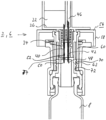
- the liquid transfer system 1 is explained below using a medical syringe 4 provided with a first connecting component 2 and a container 8 for medical substances or drugs provided with a second connecting component 6.
- a medical syringe 4 provided with a first connecting component 2
- a container 8 for medical substances or drugs provided with a second connecting component 6.
- Fig. 1 the components, i.e. the syringe 4 and the container 8, are shown in a longitudinal section in a separate, still separated state;
- Figs. 2 and 3 show the components analogously ( Fig 3 detail) in a longitudinal section after the connection has been established.
- the syringe 4 comprises a hollow body 10 which is cylindrical or tubular in accordance with a conventional design and forms a syringe housing, in which a piston 12 whose external dimensions are precisely adapted to the inner contour of the hollow body 10 is slidably guided.
- the piston 12 is arranged at the end on an actuating plunger 16 which is guided sealingly through a cover plate 14 and which in turn is provided with a pusher plate 20 at its free end 18.
- the piston 12 divides the internal volume of the hollow body 10 into a distal partial volume 22 intended for the absorption of liquid and a proximal partial volume 24 intended for the absorption of gases or aerosols, the volume contents of which can be changed by positioning the piston 12 within the hollow body 10 .
- the first connection component 2 is arranged at the distal end 26 of the hollow body 10 and thus of the distal partial volume 22.
- the first connecting component 2 which is considered to be independently inventive and which in the exemplary embodiment is designed integrally with the hollow body 10, but could also be designed as a separate, retrofittable component, comprises a distal end plate 30 which seals the distal partial volume 22 of the hollow body.
- the end plate 30 forms a needle holder for a needle system 32 and, on its side facing away from the partial volume 22, a tubular connecting piece 34 surrounding the needle system 32 for establishing a connection with the second connecting component 6.
- the needle system 32 is designed as a double needle system and comprises a first hollow needle 40 intended for liquid transfer and a second hollow needle 42 intended for gas transfer.
- the first hollow needle 40 protrudes with its inner end 44 into the partial volume 22 and thus forms a fluid channel for fluid exchange.
- the second hollow needle 42 is connected on the inside to a gas channel 46, which is guided in the manner of a bypass along the inner wall of the hollow body 10 into the proximal partial volume 24.
- gas or aerosol can be transferred from its distal needle tip 48 in the manner of an encapsulated embodiment into the proximal partial volume 24 or guided from there to the needle tip 48.
- the first and second hollow needles 40, 42 protrude with their distal needle tips 48, 50 from the open end of the tubular connecting piece 34.
- an elastic, comparatively easily deformable needle cap 52 is also fastened within the connecting piece 34, which sealingly encloses the distal tips 48, 50 of the hollow needles 40, 42 of the needle system in the unloaded state.
- the needle cap 52 consists of a thermoplastic elastomer (TPE).
- the connecting piece 34 is surrounded by a connecting sleeve 56 mounted on a circumferential rib 54.
- This is rotatably mounted around the needle system 32 and has an actuating edge 58, via which the user can cause rotation, and a flange jacket 60, which is provided with a thread 62 on the inside.
- the thread 62 in combination with the flange jacket 60 is designed in the exemplary embodiment as a component of a Luer connection.
- the thread 62 is designed with only one thread or thread, but can of course also have further threads and/or threads.
- the in Fig. 1 Container 8 for medical substances or medicines also shown in longitudinal section, also referred to as a vial, is correspondingly provided with a second connection component 6 designed for connection to the first connection component 2.
- This comprises a connecting piece 72 provided with a thread 70, in which a sealing plug 74 consisting of the particularly preferred material PP Purell HP 570, which is considered to be independently inventive with regard to the choice of material, is arranged is.
- the connecting piece 72 provided with the thread 70 is designed to be adapted to the flange jacket 60 and its thread 62, so that these components form a Luer connection with one another.
- the syringe 4 provided with the first connecting component 2 is first brought into contact with the container 8 provided with the second connecting component 6 in such a way that the thread 62 of the flange jacket 60 comes into engagement with the thread 70 of the connecting piece 72.
- This creates a screw connection between these components which can be further tightened by rotating the flange jacket 60, i.e. by actuating the actuating edge 58.
- the first connecting element 2 is moved further in the longitudinal direction of the syringe 4 towards the second connecting component 6 and thus the container 8.
- the needle cap 52 begins to deform due to its elastic design, and the distal needle tips 48, 50 begin to penetrate the needle cap 52.
- the distal needle tips 48, 50 completely pierce the needle cap 52 and begin to penetrate the sealing plug 74.
- the distal needle tips 48, 50 also completely pierce the closure plug 74.
- the first hollow needle 40 forms an open liquid channel and enables liquid exchange between the interior of the container 8 and the distal partial volume 22, and a gas exchange between the proximal partial volume 24 and the second hollow needle 42 and the gas channel 46 connected to it is possible Interior of the container 8 allows.
- the piston 12 can now be positioned within the syringe 4, starting from an initial state in which the piston 12 is positioned immediately adjacent to the distal end 26 of the hollow body 10 Hollow body 10 can be moved away from its distal end 26. Liquid flows from the interior of the container 8 into the distal partial volume 22 of the syringe 4. At the same time, the gas located in the proximal partial volume 24 is compressed so that it flows into the interior of the container 8 via the gas channel 46 and the second hollow needle 42 to equalize the pressure. This enables a safe and encapsulated media exchange between syringe 4 and container 8 without liquid or gas escaping into the environment.
- the components are separated again by loosening the screw connection.
- the hollow needles 40, 42 of the needle system 32 are pulled out of the interior of the container 8 when viewed in the longitudinal direction of the syringe 4.
- the needle tips 48, 50 have been completely pulled out of the sealing plug 74, it returns to its original shape due to the choice of material and thereby seals the interior of the container 8 from the outside again.
- the needle cap 52 begins to assume its original shape again due to its material properties, so that the needle tips 48, 50 are again completely positioned in their interior and thus the needle cap 52 the needle tips 48, 50 completely encloses again. This means that after the components have been separated from each other, the interior of the container 8 on the one hand and the interior of the hollow body 10 are completely encapsulated again.
- FIG. 4 A particularly preferred embodiment of the vial or container 8, which is considered to be independently inventive, is shown in longitudinal section in Fig. 4 shown.
- the container 8 in this embodiment comprises an outer closure cap 76 surrounding the connecting component 6, which is provided with a disposable closure 78.
- the disposable closure 78 comprises a tear-off, or alternatively or additionally, for example, a sealed sealing lid 80, which is removed when the container 8 is opened for the first time.
- This design allows problem-free and reliable identification as to whether the container 8 has already been used for liquid transfer or not, and thus makes it easier to determine whether the container 8 has already been "opened” and should therefore preferably be used for further liquid removal until it is completely emptied and should therefore be disposed of.
- a particularly advantageous embodiment of the first connecting component 2, which is considered to be independently inventive, is shown in an enlarged longitudinal section in Fig. 5 (state before the components are connected to each other) and in Fig. 6 (State when components are connected to each other).
- a spring element 82 in the exemplary embodiment a spiral spring 84, is arranged as a further component within the needle cap 52.
- the spiral spring 84 is arranged inside the needle cap 52, surrounding the needle system 32. It is supported on the one hand on the cover plate 30 of the distal partial volume 22, in which the needles 40, 42 of the needle system 32 are held, and on the other hand on the cover surface of the needle cap 52.
- the needle cap 52 is also designed in two parts and, in addition to the actual cap body 86, includes a needle guard 88 attached distally thereto, with the spiral spring 84 being supported on the bottom of the needle guard 88 in this embodiment.
- the medical syringe 4 described above, equipped with the first connection component 2, can be used, for example, for liquid transfer between different containers of the container 8 type or also for the transfer of liquids from such a container 8 into an intravenous (IV) access.
- the medical syringe 4 is connected via its connection component 2 to the associated second connection component 6 of the respective container 8 or an access interface of the intravenous access, so that liquid is drawn from the respective container 8 into the distal partial volume 22 of the syringe 4 or can be transferred from this into a corresponding container 8 or the IV access.
- the syringe 4 can also be prepared for direct injection of the liquid after being filled with the liquid transferred as medication or active ingredient and thus as an injection syringe.
- a syringe adapter 90 which is considered to be independently inventive, is provided, as seen - in longitudinal section together with the end region of the syringe 4 - in Fig. 7 before and in Fig. 8 after assembly with the syringe 4 is shown.
- Syringe adapter 90 shown in longitudinal section is designed, as shown, for mounting on the medical syringe 4 using its first connecting component 2.
- the syringe adapter 90 is correspondingly provided with a further connection component 92 which is suitably designed for connection to the first connection component 2.
- this includes a connecting piece 96 provided with a thread 94.
- This just like the corresponding components of the second connecting component 6 - is designed to be adapted to the flange jacket 60 of the first connecting component 2 and its thread 62, so that these components form a Luer connection with each other.
- a contact element 98 for establishing a media-side connection to the needle system 32 is arranged within the connecting piece 96.
- the contact element 98 is essentially formed by a plug-like base body 100, which has a cavity or a cavity 102 for receiving the needle tip 50 of the first hollow needle 40 intended for liquid transfer and a further cavity or a further cavity 104 for receiving the needle tip 48 of the second hollow needle 42 connected to the gas channel 46 on the media side.
- An encapsulated gas exchange is not provided in this case, and accordingly the further cavity 104 is designed in the manner of a blind hole and is not connected to any other media channels.
- the cavity 102 is designed and provided as a transfer space for forwarding the liquid fed in via the hollow needle 40 from the distal partial volume 22 of the syringe 4.
- a transfer needle 106 opens into the cavity 102.
- This is arranged within a cylindrical or tubular hollow body 108 which forms the housing of the syringe adapter 90.
- a needle holder 112 is attached, in which the hollow needle 114 intended for injecting the active ingredient is stored in a bearing sleeve 116.
- the needle holder 112 could be designed in one piece with the hollow body 108 forming the housing.
- the needle holder 112 is designed as a separate component in an embodiment that is considered to be independently inventive.
- the needle holder 112 is plugged or can be plugged onto the hollow body 108 forming the housing, but could also be designed to be screwed on by means of a thread, for example a Luer thread.
- the hollow body 108 is surrounded on the outside by a needle protection sleeve 118 that can be moved in the longitudinal direction.
- the syringe 4 can also be used to inject the liquid into an infusion bag ("IV bag") after it has been filled with the liquid transferred as medication or active ingredient.
- IV bag infusion bag
- the medication can be added to the actual infusion fluid or provided directly as an infusion fluid.
- the active ingredient can then be administered from the infusion bag via an intravenous application system.
- an adapter 120 which is considered to be independently inventive, is provided for an infusion bag 122, as shown together with the infusion bag 122 in a perspective view in Fig. 9 and - each in longitudinal section together with the end region of the syringe 4 - in Fig. 10 before and in Fig. 11 after assembly with the syringe 4 is shown.
- the infusion bag 122 acc. Fig. 9 also referred to as an "IV bag", is intended for connection to an intravenous application system with which a liquid held in the infusion bag 122, for example a medication or an isotonic liquid or the like, can be administered to a patient as an infusion.
- the infusion bag 122 is provided with a connection piece 124, via which a media exchange, in particular the introduction or removal of liquid into/from the interior of the infusion bag 122, is possible.
- the adapter 120 is provided, which is in the Figs. 9 to 11 is shown in the state already mounted on the connection piece 124 of the infusion bag.
- Adapter 120 shown in longitudinal section is designed, as shown, for mounting on the medical syringe 4 using its first connecting component 2.
- the adapter 120 is correspondingly provided with a further connection component 126 which is suitably designed for connection to the first connection component 2.
- this includes a connecting piece 130 provided with a thread 128. This is connected to the flange jacket 60 - just like the corresponding components of the second connecting component 6 and the corresponding components of the further connecting component 92 first connecting component 2 and its thread 62 are adapted so that these components form a Luer connection with each other.
- a contact element 132 for establishing a media-side connection to the needle system 32 is arranged within the connecting piece 130.
- the contact element 132 is - in a similar embodiment to the aforementioned contact element 98 - essentially formed by a base body 134, which has a cavity or a cavity 136 for receiving the needle tip 50 of the first hollow needle 40 intended for liquid transfer and a further cavity or a further cavity 138 for receiving the needle tip 48 of the second hollow needle 42 connected to the gas channel 46 on the media side.
- An encapsulated gas exchange is not provided in this case, and accordingly the further cavity 138 is designed in the manner of a blind hole and is not connected to any other media channels.
- the cavity 136 is designed and provided as a transfer space for forwarding the liquid fed in via the hollow needle 40 from the distal partial volume 22 of the syringe 4.
- the cavity 136 goes into a media channel 142 arranged in a connecting piece 140 or a grommet in the manner of an axial central bore, the free end 144 of which communicates on the media side with the interior of the infusion bag 122.
Description
Die Erfindung betrifft ein Flüssigkeitstransfersystem zum Transfer von medizinischen Substanzen oder Arzneimitteln. Sie bezieht sich weiter auf Komponenten und Bauteile eines solchen Transfersystems, insbesondere dessen Verbindungskomponenten und die mit solchen Verbindungskomponenten ausgerüsteten Bauteile wie Spritzen, Container (Phiolen) oder Applikationssysteme.The invention relates to a liquid transfer system for transferring medical substances or drugs. It further relates to components and components of such a transfer system, in particular its connecting components and the components equipped with such connecting components, such as syringes, containers (vials) or application systems.
In modernen medizinischen Verfahren oder Therapien können Medikamente oder Substanzen zum Einsatz kommen, die an sich eigentlich toxisch oder auf sonstige Weise schädlich oder gefährlich sind. Für das mit der Handhabung solcher Substanzen betraute Personal, wie beispielsweise Apotheker und Krankenschwestern, können somit akute und langfristige Gesundheitsrisiken entstehen, gerade wenn es wiederholt Medikamenten oder Lösungsmitteln ausgesetzt ist, die während der Zubereitung, der Verabreichung von Medikamenten und anderen ähnlichen Behandlungen in die Luft entweichen könnten. Dieses Problem kann besonders schwerwiegend sein, wenn es sich um Zytotoxine, antivirale Medikamente, Antibiotika oder Radiopharmazeutika handelt. Die durch die Exposition gegenüber diesen Medikamenten potentiell entstehenden Gesundheitsrisiken umfassen ein erhöhtes Krebsrisiko, genetische Veränderungen und dergleichen. Des Weiteren können auch Probe- oder Blutabnahmen bei viralen Infektionen oder dergleichen ein erhöhtes Risiko für das handhabende Personal bedingen.Modern medical procedures or therapies may use medications or substances that are actually toxic or otherwise harmful or dangerous. Personnel involved in the handling of such substances, such as pharmacists and nurses, may therefore pose acute and long-term health risks, particularly if they are repeatedly exposed to medications or solvents released into the air during preparation, administration of medications and other similar treatments could escape. This problem can be particularly serious when cytotoxins, antiviral drugs, antibiotics or radiopharmaceuticals are involved. The health risks potentially arising from exposure to these drugs include increased risk of cancer, genetic changes, and the like. Furthermore, taking samples or blood in the event of viral infections or the like can also pose an increased risk for the handling staff.
Bei der Durchführung von Infusionen ist es des Weiteren oft notwendig, ein Medikament oder einen Wirkstoff in die Infusionsflüssigkeit, in einen Infusionsbeutel oder in einen anderen Infusionsbehälter zu injizieren. Dies geschieht oft durch das Durchstoßen eines Septums oder einer anderen Flüssigkeitsbarriere einer Injektionsöffnung am Infusionsbeutel oder an der Infusionsleitung mit der Nadel einer mit der betreffenden medizinischen Flüssigkeit gefüllten Spritze. Doch schon vor diesem Schritt kann es notwendig sein, die medizinische Flüssigkeit aus einem Fläschchen oder einer Phiole in eine Spritze und dann von der Spritze in einen Sekundärbehälter zu transferieren. In jedem dieser Schritte kann das Personal durch Kontamination mit der medizinischen Flüssigkeit in Berührung kommen. Diese Kontamination kann verdampfte medizinische Flüssigkeit oder Aerosol in der Luft sein. Die Verunreinigungen können das Personal durch die Lunge oder durch verdampftes medizinisches Fluid oder Aerosol in der Luft kontaminieren, das auf der Haut kondensiert und danach in die Haut der betroffenen Person eindringt. Einige Medikamente sind sogar dafür bekannt, dass sie in Schutzhandschuhe eindringen und dadurch das Personal verunreinigen.When carrying out infusions, it is often necessary to inject a medication or an active ingredient into the infusion fluid, into an infusion bag or into another infusion container. This often happens through this Piercing a septum or other fluid barrier of an injection port on the infusion bag or infusion line with the needle of a syringe filled with the medical fluid in question. However, even before this step, it may be necessary to transfer the medical fluid from a bottle or vial to a syringe and then from the syringe to a secondary container. In each of these steps, personnel may come into contact with the medical fluid due to contamination. This contamination can be vaporized medical fluid or airborne aerosol. The contaminants can contaminate personnel through the lungs or through vaporized medical fluid or aerosol in the air that condenses on the skin and then penetrates the affected person's skin. Some medications have even been known to penetrate protective gloves, thereby contaminating staff.
Einerseits aus den genannten Gründen des Gesundheitsschutzes, andererseits aber auch im Hinblick auf den Umstand, dass in jüngster Zeit Medikamente mit einem äußerst hohen Dosispreis zugelassen worden sind, ist es dringend wünschenswert oder sogar notwendig, die Abgabe auch kleinster Mengen solcher Medikamente oder Wirkstoffe an die Umgebung zuverlässig zu vermeiden. Zu diesem Zweck sind so genannte geschlossene Transfersysteme gebräuchlich, bei denen in der Art einer gekapselten Ausführung in jeder Phase des Flüssigkeitstransfers sichergestellt ist, dass der Wirkstoff oder die von diesem freigesetzten Gase oder Aerosole nicht in die Umgebung entweichen können.On the one hand, for the reasons of health protection mentioned, but on the other hand also in view of the fact that medications with an extremely high dose price have recently been approved, it is urgently desirable or even necessary to distribute even the smallest quantities of such medications or active ingredients to the reliably avoid surroundings. For this purpose, so-called closed transfer systems are in use, in which an encapsulated design ensures in every phase of the liquid transfer that the active ingredient or the gases or aerosols released by it cannot escape into the environment.
Derartige Flüssigkeitstransfersysteme umfassen üblicherweise eine erste Verbindungskomponente oder einen ersten Adapter zum Anschluss an einen ersten Fluidbehälter, wie beispielsweise eine Spritze, und eine zweite Verbindungskomponente oder einen zweiten Adapter zum Anschluss an einen Wirkstoffbehälter, eine Phiole, eine zweite Spritze oder eine intravenöse Leitung, die einen Flüssigkeitszugang zum Kreislauf des Patienten bereitstellt. Dabei kann der Arzt oder die behandelnde Person beispielsweise eine Spritze über den Spritzenadapter und den zugeordneten Phiolen Adapter mit einer Phiole verbinden und das darin befindliche Medikament in die Spritze einsaugen. Anschließend werden die Adapter getrennt, und die Spritze wird über den Spritzenadapter und einen zugeordneten Leitungsadapter mit einer intravenösen Leitung oder einem intravenösen Zugang verbunden, so dass das in der Spritze befindliche Medikament an den Patienten verabreicht werden kann.Such liquid transfer systems typically include a first connection component or a first adapter for connection to a first fluid container, such as a syringe, and a second connection component or a second adapter for connection to a drug container, a vial, a second syringe or an intravenous line, which includes a Provides fluid access to the patient's circulation. In this case, the doctor or the person treating the patient can, for example, connect a syringe to a vial via the syringe adapter and the associated vial adapter and suck the medication contained therein into the syringe. The adapters are then separated, and the syringe is connected to an intravenous line or access via the syringe adapter and an associated line adapter so that the medication in the syringe can be administered to the patient.
Ein solches Flüssigkeitstransfersystem einschließlich der erforderlichen Komponenten wie Verbindungsadapter und dergleichen ist beispielsweise aus der
Der Erfindung liegt die Aufgabe zugrunde, ein Flüssigkeitstransfersystem zum Transfer von medizinischen Substanzen oder Arzneimitteln der oben genannten Art, einschließlich seiner wesentlichen Komponenten wie insbesondere der Verbindungskomponenten, anzugeben, mit dem bei besonders einfach gehaltener Handhabung die unbeabsichtigte Abgabe oder Freisetzung von Wirkstoffbestandteilen oder Gasen oder Aerosolen hiervon besonders zuverlässig vermieden ist. Bezüglich einer ersten Verbindungskomponente, insbesondere für eine medizinischen Spritze, wird diese Aufgabe erfindungsgemäß gelöst mit einem eine Anzahl von Hohlnadeln umfassenden, in einem rohrförmigen, von einem Flanschmantel umgebenen Verbindungsstutzen angeordneten Nadelsystem und mit einer innerhalb des Verbindungsstutzens angeordneten, die distale(n) Spitze(n) der oder jeder Nadel des Nadelsystems im unbelasteten Zustand dichtend umschließenden elastischen Nadelkappe, wobei der Flanschmantel um das Nadelsystem und um die dieses umschließende Nadelkappe rotierbar ist und mit einem Gewinde zum Anschluss an eine zweite Verbindungskomponente versehen ist.The invention is based on the object of specifying a liquid transfer system for the transfer of medical substances or drugs of the type mentioned above, including its essential components such as in particular the connecting components, with which the unintentional delivery or release of active ingredient components or gases or aerosols is particularly easy to handle is particularly reliably avoided. With regard to a first connection component, in particular for a medical syringe, this object is achieved according to the invention with a needle system comprising a number of hollow needles, arranged in a tubular connecting piece surrounded by a flange jacket, and with a distal tip(s) arranged within the connecting piece ( n) the elastic needle cap sealingly surrounding the or each needle of the needle system in the unloaded state, the flange jacket being rotatable around the needle system and around the needle cap surrounding it and being provided with a thread for connection to a second connecting component.
Vorteilhafte Ausgestaltungen der Erfindung sowie auch als eigenständig erfinderisch angesehene weitere Aspekte oder Varianten sind Gegenstand der Unteransprüche und/oder der nachfolgenden Figurenbeschreibung entnehmbar.Advantageous embodiments of the invention as well as further aspects or variants that are considered to be independently inventive can be found in the subclaims and/or the following description of the figures.
Die Erfindung geht von der Überlegung aus, dass für einen sicheren und verlustfreien Flüssigkeitstransfer zwischen Spritze und weiterem Behältnis, beispielsweise einer Phiole, eine stabile und dichtende Verbindung zwischen den jeweiligen Verbindungskomponenten besonders bedeutsam ist. Dazu muss einerseits eine geeignete Dichtung an den Grenz- oder Kontaktflächen beider Verbindungskomponenten bereitgestellt werden, und andererseits sollte ein geeigneter Kraftschluss zwischen den Verbindungskomponenten, zum einen zum Zweck der mechanischen Stabilisierung der Komponenten relativ zueinander und zum anderen zum Zweck einer Verbesserung der Dichtwirkung durch Anpressen, hergestellt werden. Bei den bekannten Systemen, beispielsweise dem aus der
Abweichend von diesem Auslegungsprinzip und im Hinblick auf eine besonders gute Dosierbarkeit der aufgewandten Haltekräfte ist nunmehr eine Verschraubung der Verbindungskomponenten miteinander vorgesehen, wobei die Haltekraft zwischen den Verbindungselementen durch geeignete Betätigung der Verschraubung modifiziert und bedarfsgerecht eingestellt werden kann. Ergänzend hierzu ist als Versiegelung und abdichtender Abschluss für die als eigentliche Transferkanäle in der Verbindungskomponente vorgesehenen Hohlnadeln eine Nadelkappe aus vergleichsweise weichem, elastischem Material vorgesehen. Diese wird bei Kontakt mit dem anderen Verbindungselement verformt und zurückgedrängt, so dass die in Inneren befindlichen Hohlnadeln sie durchstoßen und damit zur Herstellung der medienseitigen Verbindung nach außen freigelegt werden. Je nach Einstellung der Verschraubung kann die Verformung der Nadelkappe dabei unterschiedlich sein, so dass entsprechend auch die durch die Nadelkappe und deren Kontakt mit der Gegenfläche gegebene Dichtwirkung geeignet optimiert werden kann. Nach Abschluss des Flüssigkeitstransfers und nach der Trennung der Komponenten nimmt die Nadelkappe aufgrund der Elastizität ihres Grundmaterials jedoch wieder ihre ursprüngliche Form ein und umschließt somit die Nadelspitzen wieder, so dass auch nach Abschluss des Transfers eine zuverlässige Umhüllung und Versiegelung des Spritzeninneren einschließlich der Nadelauslässe gewährleistet ist.Deviating from this design principle and in view of a particularly good controllability of the holding forces applied, a screw connection of the connecting components to one another is now provided, whereby the holding force between the connecting elements can be modified and adjusted as required by suitable actuation of the screw connection. In addition, a needle cap made of comparatively soft, elastic material is provided as a seal and sealing closure for the hollow needles provided as actual transfer channels in the connecting component. This is deformed and pushed back when it comes into contact with the other connecting element, so that the hollow needles located inside pierce it and are thus exposed to the outside in order to produce the media-side connection. Depending on the setting of the screw connection, the deformation of the needle cap can be different, so that the sealing effect provided by the needle cap and its contact with the counter surface can be suitably optimized. However, after the liquid transfer has been completed and the components have been separated, the needle cap returns to its original shape due to the elasticity of its base material and thus encloses the needle tips again, so that a reliable covering and sealing of the interior of the syringe, including the needle outlets, is guaranteed even after the transfer has been completed .
Ganz besonders bevorzugt ist die Nadelkappe dabei Material mit sehr guter Druckverformungsresistenz und besonders guten Druckrelaxations-Eigenschaften ausgeführt. Ganz besonders bervorzugt ist dafür ein thermoplastisches Elastomer (TPE) vorgesehen.The needle cap is particularly preferably a material with very good resistance to compression deformation and particularly good pressure relaxation properties executed. A thermoplastic elastomer (TPE) is particularly preferred for this purpose.
In ganz besonders vorteilhafter und als eigenständig erfinderisch angesehener Ausgestaltung ist dabei innerhalb der Nadelkappe ein Federelement, besonders bevorzugt eine Spiralfeder, angeordnet, das nach Abschluss des Transfers die Wiederherstellung der ursprünglichen Form der Nadelkappe unterstützt. Dabei kann beispielsweise eine Spiralfeder, das Nadelsystem umgebend, innerhalb der Nadelkappe angeordnet sein, die sich einerseits an einer Bodenplatte, in der die Nadeln des Nadelsystems gehalten sind, und andererseits an der Deckelfläche der Nadelkappe abstützt. Bei der Verformung der Nadelkappe infolge des Kontakts mit dem anderen Verbindungselement wird das Federelement zusammen mit der Nadelkappe mit verformt und dabei vorgespannt. Nach Abschluss des Flüssigkeitstransfers und nach der Trennung der Komponenten entspannt sich das Federelement wieder und unterstützt damit die erwünschte Rückverformung der Nadelkappe, bis diese wieder ihre ursprüngliche, die freilegenden Spitzen des Nadelsystems vollständig umschließende Form einnimmt.In a particularly advantageous embodiment that is considered to be independently inventive, a spring element, particularly preferably a spiral spring, is arranged within the needle cap, which supports the restoration of the original shape of the needle cap after the transfer has been completed. For example, a spiral spring surrounding the needle system can be arranged within the needle cap, which is supported on the one hand on a base plate in which the needles of the needle system are held and on the other hand on the cover surface of the needle cap. When the needle cap is deformed as a result of contact with the other connecting element, the spring element is deformed together with the needle cap and thereby prestressed. After the liquid transfer has been completed and the components have been separated, the spring element relaxes again and thus supports the desired deformation of the needle cap until it returns to its original shape, which completely encloses the exposed tips of the needle system.
Um einen vollständig gekapselten Flüssigkeitstransfer zu ermöglichen, bei dem weder Flüssigkeitsverluste noch ein Entweichen von Gasen oder Aerosolen aus der Flüssigkeit an die Umgebung in Kauf genommen werden müssen, ist das Nadelsystem vorteilhafterweise als Doppelnadelsystem ausgeführt. Dieses umfasst, analog zu der aus der
Um eine besonders zuverlässige und sichere medienseitige Verbindung mittels des Nadelsystems zu ermöglichen, ist erfindungsgemäß der Flanschmantel frei um das Nadelsystem und um die dieses umschließende Nadelkappe herum rotierbar ausgeführt. Damit ist die Nutzung des Verbindungsgewindes, mit dem die mechanisch vergleichsweise stabile und damit besonders günstige Verschraubung der Verbindungskomponenten miteinander bewirkt werden soll, auf besonders einfache und günstige Weise und insbesondere ohne Störung oder Beeinträchtigung der medienseitigen Verbindung über das Nadelsystem möglich. Dies kann in besonders vorteilhafter Weise genutzt werden, um die Nadeln des Nadelsystems hinsichtlich ihrer Dimensionierung besonders fein, insbesondere vergleichsweise dünnwandig und mit vergleichsweise gering gehaltenem Außendurchmesser, ausführen zu können.In order to enable a particularly reliable and secure media-side connection by means of the needle system, according to the invention the flange jacket is designed to be freely rotatable around the needle system and around the needle cap surrounding it. This means that the use of the connecting thread, with which the mechanically comparatively stable and therefore particularly favorable screwing of the connecting components to one another is to be achieved, is particularly simple and inexpensive and in particular without disruption or impairment the media-side connection is possible via the needle system. This can be used in a particularly advantageous manner in order to be able to design the needles of the needle system particularly finely in terms of their dimensions, in particular comparatively thin-walled and with a comparatively small outer diameter.
Bezüglich einer zweiten Verbindungskomponente, insbesondere für einen Container für medizinische Substanzen oder Arzneimittel oder für ein Transfersystem für medizinische Substanzen oder Arzneimittel, und insbesondere zum Anschluss an die vorstehend beschriebene erste Verbindungskomponente, wird die vorstehend genannte Aufgabe in als eigenständig erfinderisch angesehener Ausführung gelöst mit einem mit einem zum Anschluss an dem Gewinde des Flanschmantels der ersten Verbindungskomponente vorgesehenen Gewinde versehenen Verbindungsstutzen, in dem ein aus einem Polypropylen, bevorzugt aus PP Purell HP570, bestehender Verschlussstopfen angeordnet ist.With regard to a second connection component, in particular for a container for medical substances or drugs or for a transfer system for medical substances or drugs, and in particular for connection to the first connection component described above, the above-mentioned task is solved in an embodiment that is considered to be independently inventive with a a connecting piece provided for connection to the thread of the flange jacket of the first connecting component, in which a sealing plug made of a polypropylene, preferably made of PP Purell HP570, is arranged.
Im Gegensatz zu üblichen Systemen, bei denen beispielsweise Container für medizinische Substanzen oder Arzneimittel mit einem siegelartigen Verschlussdeckel aus Aluminium oder dergleichen verschlossen sind, kann durch eine solche zweite Verbindungskomponente der Container wiederverschließbar ausgeführt sein. Bei den herkömmlichen Systemen wird nämlich bei der erstmaligen Verwendung der siegelartige Verschlussdeckel durch das Nadelsystem durchstochen, so dass er nach erfolgtem Flüssigkeitstransfer und der Trennung der Komponenten offen bleibt, so dass die im Container befindliche Substanz vollständig transferiert werden muss; eventuell im Container verbleibende Restbestände oder auch Gase oder Aerosole müssen dann gesondert und in einem sicheren und gekapselten System entsorgt werden. Im vorliegenden, als erfinderisch angesehenen System führt hingegen die Ausführung des Verschlussstopfens dazu, dass das Material nach Entfernung des Nadelsystems wieder seine ursprüngliche Position einnimmt und den Container somit erneut dichtend verschließt. Somit ist in gewissem Umfang eine Mehrfachnutzung des Containers und damit eine chargenweise Entnahme des darin befindlichen Wirkstoffs möglich.In contrast to conventional systems in which, for example, containers for medical substances or drugs are closed with a seal-like closure lid made of aluminum or the like, the container can be designed to be reclosable using such a second connecting component. In conventional systems, when used for the first time, the seal-like closure lid is pierced by the needle system so that it remains open after the liquid has been transferred and the components have been separated, so that the substance in the container must be completely transferred; Any residues or gases or aerosols remaining in the container must then be disposed of separately and in a safe and encapsulated system. In the present system, which is considered inventive, however, the design of the sealing plug causes the material to return to its original position after the needle system has been removed and thus seal the container again. This means that, to a certain extent, the container can be used multiple times and the active ingredient contained therein can be removed in batches.
Zur Herstellung der vorgesehenen Schraubverbindung der Komponenten miteinander ist das Gewinde der zweiten Verbindungskomponente vorteilhafterweise hinsichtlich Auslegung, Dimensionierung und dergleichen an das Gewinde der ersten Verbindungskomponente angepasst. Ganz besonders vorteilhaft bilden die genannten Komponenten dabei ein Luer-Gewinde.In order to produce the intended screw connection of the components to one another, the thread of the second connecting component is advantageously adapted to the thread of the first connecting component in terms of design, dimensioning and the like. It is particularly advantageous for the components mentioned to form a Luer thread.
Als eigenständig erfinderisch angesehen wird ebenfalls ein mit einer solchen zweiten Verbindungskomponente ausgerüsteter Container für medizinische Substanzen oder Arzneimittel. In besonders vorteilhafter Ausgestaltung ist dieser mit einer äußeren, die Verbindungskomponente umgebenden Kappe versehen, die mit einem Einwegverschluss versehen ist. Dieser Einwegverschluss, der beispielsweise einen abreissbaren oder verplombt ausgeführten Siegeldeckel umfassen kann, erlaubt eine problemlose und zuverlässige Identifikation, ob der Container bereits zum Flüssigkeitstransfer verwendet wurde oder nicht, und erleichtert somit die Zuordnung, ob der Container bereits "angebrochen" ist und somit bevorzugt für eine weitere Flüssigkeitsentnahme verwendet werden sollte, bis er vollständig entleert ist und somit entsorgt werden sollte.A container for medical substances or medicines equipped with such a second connecting component is also considered to be independently inventive. In a particularly advantageous embodiment, this is provided with an outer cap surrounding the connecting component, which is provided with a disposable closure. This disposable closure, which can include, for example, a tear-off or sealed sealing lid, allows problem-free and reliable identification of whether the container has already been used for liquid transfer or not, and thus makes it easier to determine whether the container has already been "opened" and is therefore preferred for Further fluid removal should be used until it is completely drained and should therefore be discarded.
Die Erfindung betrifft weiterhin in als eigenständig erfinderisch angesehener Ausführung eine medizinische Spritze, die an ihrem distalen Ende mit einer Verbindungskomponente nach einer der vorstehend beschriebenen Ausführungen versehen ist. Des Weiteren betrifft die Erfindung in ebenfalls als eigenständig erfinderisch angesehener Ausgestaltung ein Flüssigkeitstransfersystem zum Transfer von medizinischen Substanzen oder Arzneimitteln mit einer ersten Verbindungskomponente der vorstehend beschriebenen Ausgestaltung und mit einer, hinsichtlich der Dimensionierung und Ausführung der Verbindungstutzen an diese angepasst, einer zweiten Verbindungskomponente der vorstehend beschriebenen Ausgestaltung.The invention further relates, in an embodiment considered to be independently inventive, to a medical syringe which is provided at its distal end with a connecting component according to one of the embodiments described above. Furthermore, the invention relates, in an embodiment that is also considered to be independently inventive, to a liquid transfer system for the transfer of medical substances or medicines with a first connection component of the embodiment described above and with a second connection component of the one described above, which is adapted to the dimensioning and design of the connecting pieces Design.
Ein Ausführungsbeispiel der Erfindung wird anhand einer Zeichnung näher erläutert. Darin zeigen:
- Fig. 1
- eine über Verbindungskomponenten eines Flüssigkeitstransfersystems mit einem Container für Arzneimittel oder Medikamente verbindbare medizinische Spritze im Längsschnitt,
- Fig. 2
- die Komponenten gem.
Fig. 1 im Längsschnitt im verbundenen Zustand, - Fig. 3
- einen vergrößerten Ausschnitt der Komponenten nach
Fig. 2 , - Fig. 4
- eine besonders bevorzugte Ausführungsform eines Containers zur Verwendung im Flüssigkeitstransfersystem nach
Fig. 1 , - Fig. 5
- im Längsschnitt eine besonders bevorzugte Ausführungsform einer ersten Verbindungskomponente zur Verwendung im Flüssigkeitstransfersystem nach
Fig. 1 , im Zustand vor der Verbindung der Komponenten miteinander, - Fig. 6
- die Verbindungskomponente gem.
Fig. 5 im Längsschnitt bei miteinander verbundenen Komponenten, - Fig. 7
- einen Spritzenadapter vor der Montage mit einer zugeordneten Spritze im Längsschnitt,
- Fig. 8
- die Spritze gem.
Fig. 7 mit montiertem Spritzenadapter, - Fig. 9
- einen Infusionsbeutel mit Adapter,
- Fig. 10
- den mit Adapter versehenen Infusionsbeutel nach
Fig. 9 vor der Montage mit einer zugeordneten Spritze im Längsschnitt, und - Fig. 11
- die Spritze gem.
Fig. 10 mit montiertem Infusionsbeutel.
- Fig. 1
- A longitudinal section of a medical syringe that can be connected to a container for drugs or medication via connecting components of a liquid transfer system,
- Fig. 2
- the components according to
Fig. 1 in longitudinal section in the connected state, - Fig. 3
- an enlarged section of the components
Fig. 2 , - Fig. 4
- a particularly preferred embodiment of a container for use in the liquid transfer system
Fig. 1 , - Fig. 5
- in longitudinal section a particularly preferred embodiment of a first connection component for use in the liquid transfer system
Fig. 1 , in the state before the components are connected to each other, - Fig. 6
- the connection component according to
Fig. 5 in longitudinal section with components connected to one another, - Fig. 7
- a syringe adapter before assembly with an assigned syringe in a longitudinal section,
- Fig. 8
- the syringe according to
Fig. 7 with mounted syringe adapter, - Fig. 9
- an infusion bag with adapter,
- Fig. 10
- the infusion bag provided with an adapter
Fig. 9 before assembly with an assigned syringe in longitudinal section, and - Fig. 11
- the syringe according to
Fig. 10 with mounted infusion bag.
Gleiche Teile sind in allen Figuren mit denselben Bezugszeichen versehen. Die Erfindung wird nachfolgend vorwiegend anhand des Ausführungsbeispiels erläutert, bei dem eine medizinische Spritze mit einer ersten Verbindungskomponente der genannten Art und ein Container für medizinische Substanzen oder Arzneimittel mit einer zweiten Verbindungskomponente der beschriebenen Art ausgerüstet ist. Selbstverständlich sind aber auch andere Ausführungen denkbar und von der vorliegenden Erfindung umfasst, bei der andere Bestandteile eines medizinischen Systems, beispielsweise eine Zugangsschnittstelle zu einem intravenösen Applikationssystem oder einen Adapter für einen Infusionsbeutel ("IV-Bag"), mit einer solchen zweiten Verbindungskomponente, oder auch eine "inverse Anordnung", bei der eine medizinische Spritze mit der zweiten Verbindungskomponente und das jeweils andere Bauteil, also beispielsweise ein Container oder eine Zugangsschnittstelle, mit einer solchen ersten Verbindungskomponente versehen ist. Ebenso sind selbstverständlich sind aber auch andere Ausführungen im nicht-medizinischen Bereich denkbar und von der vorliegenden Erfindung umfasst, bei denen unter zuverlässigem Gas- oder Materialabschluss Flüssigkeitstransfers vorgenommen werden müssen, ohne dass die handhabenden Personen einer Exposition ausgesetzt sind, beispielsweise bei Anwendungen in der Verfahrenstechnik oder für gefährliche chemische Prozesse und dergleichen.The same parts are given the same reference numbers in all figures. The invention is explained below primarily using the exemplary embodiment in which a medical syringe is equipped with a first connection component of the type mentioned and a container for medical substances or drugs is equipped with a second connection component of the type described. Of course, other embodiments are also conceivable and covered by the present invention, in which other components of a medical system, for example an access interface to an intravenous application system or an adapter for an infusion bag ("IV bag"), with such a second connection component, or also an "inverse arrangement" in which a medical syringe is provided with the second connection component and the other component, for example a container or an access interface, is provided with such a first connection component. Of course, other embodiments in the non-medical area are also conceivable and covered by the present invention, in which liquid transfers must be carried out with reliable gas or material exclusion without the people handling the fluid being exposed to exposure, for example in applications in process engineering or for dangerous chemical processes and the like.
Das erfindungsgemäße Flüssigkeitstransfersystem 1 wird nachfolgend somit anhand einer mit einer ersten Verbindungskomponente 2 versehenen medizinischen Spritze 4 und eines mit einer zweiten Verbindungskomponente 6 versehenen Containers 8 für medizinische Substanzen oder Arzneimittel erläutert. In
Die Spritze 4 umfasst einen entsprechend einer herkömmlichen Bauweise zylindrisch oder rohrförmig ausgeführten, ein Spritzengehäuse bildenden Hohlkörper 10, in dem ein in seinen Außenabmessungen passgenau an die Innenkontur des Hohlkörpers 10 angepasster Kolben 12 verschiebbar geführt ist. Der Kolben 12 ist endseitig an einem dichtend durch eine Deckelplatte 14 geführten Betätigungsstö-ßel 16 angeordnet, der seinerseits an seinem freien Ende 18 mit einer Drückerplatte 20 versehen ist. Der Kolben 12 teilt das Innenvolumen des Hohlkörpers 10 in ein distales, für die Aufnahme von Flüssigkeit vorgesehenes Teilvolumen 22 und ein proximales, für die Aufnahme von Gasen oder Aerosolen vorgesehenes Teilvolumen 24, deren Volumeninhalte durch die Positionierung des Kolbens 12 innerhalb des Hohlkörpers 10 veränderbar sind. Die erste Verbindungskomponente 2 ist dabei am distalen Ende 26 des Hohlkörpers 10 und damit des distalen Teilvolumens 22 angeordnet.The
Die als eigenständig erfinderisch angesehene erste Verbindungskomponente 2, die im Ausführungsbeispiel integral mit dem Hohlkörper 10 ausgeführt, aber auch als separate, nachrüstbare Komponente ausgeführt sein könnte, umfasst eine distale Endplatte 30. die das distale Teilvolumen 22 des Hohlkörpers dichtend abschließt. Die Endplatte 30 bildet einen Nadelhalter für ein Nadelsystem 32 und auf ihrer vom Teilvolumen 22 abgewandten Seite einen das Nadelsystem 32 umgebenden, rohrförmig ausgestalteten Verbindungsstutzen 34 zur Herstellung einer Verbindung mit der zweiten Verbindungskomponente 6 aus.The first connecting
Das Nadelsystem 32 ist im Ausführungsbeispiel als Doppelnadelsystem ausgeführt und umfasst eine erste, für den Flüssigkeitstransfer vorgesehenen Hohlnadel 40 und eine zweite, für einen Gastransfer vorgesehene Hohlnadel 42. Die erste Hohlnadel 40 ragt dabei mit ihrem inneren Ende 44 in das Teilvolumen 22 hinein und bildet somit einen Flüssigkeitskanal für den Flüssigkeitsaustausch. Die zweite Hohlnadel 42 hingegen ist innenseitig mit einem Gaskanal 46 verbunden, der in der Art eines Bypasses an der Innenwand des Hohlkörpers 10 entlang bis hinein in das proximale Teilvolumen 24 geführt ist. Über die zweite Hohlnadel 42 kann von deren distaler Nadelspitze 48 aus somit in der Art einer gekapselten Ausführung Gas oder Aerosol in das proximale Teilvolumen 24 überführt oder von diesem aus zur Nadelspitze 48 hin geführt werden. Analog zu der in der
Die erste und die zweite Hohlnadel 40, 42 ragen mit ihren distalen Nadelspitzen 48, 50 aus dem offenen Ende des rohrförmigen Verbindungsstutzens 34 heraus. Um eine zuverlässige Kapselung des Systems zu gewährleisten, ist zudem innerhalb des Verbindungsstutzens 34 eine elastische, vergleichsweise leicht verformbare Nadelkappe 52 befestigt, die die distalen Spitzen 48, 50 der Hohlnadeln 40, 42 des Nadelsystems im unbelasteten Zustand dichtend umschließt. In der im Ausführungsbeispiel gezeigten besonders bevorzugten Ausführungsform besteht die Nadelkappe 52 dabei aus einem thermoplastischen Elastomer (TPE). Bei Herstellung einer Verbindung mit der zweiten Verbindungskomponente 6, insbesondere durch Andrücken an eine vorgesehene Kontaktplatte, verformt sich die Nadelkappe 52, wobei die distalen Spitzen 48, 50 die Nadelkappe 52 durchstoßen und somit frei liegen, so dass ein Medienaustausch ermöglicht wird.The first and second
Außenseitig ist der Verbindungsstutzen 34 von einer auf einer umlaufenden Rippe 54 gelagerten Verbindungsmuffe 56 umgeben. Diese ist um das Nadelsystem 32 rotierbar gelagert und weist einen Betätigungsrand 58, über den der Nutzer eine Rotation bewirken kann, und einen Flanschmantel 60 auf, der innenseitig mit einem Gewinde 62 versehen ist. Das Gewinde 62 in Kombination mit dem Flanschmantel 60 ist dabei im Ausführungsbeispiel als Komponente einer Luer-Verbindung ausgestaltet. Im Ausführungsbeispiel ist das Gewinde 62 dabei lediglich mit einem Gewindegang oder Gewindezug ausgeführt, kann aber selbstverständlich aber auch noch weitere Gewindegänge und/oder Gewindezüge aufweisen.On the outside, the connecting
Der in
Zur Herstellung der medienseitigen Verbindung der Verbindungskomponenten 2, 6 miteinander, wie sie in der Gesamtschau in
Bei weiterer Betätigung der Schraubverbindung bis hin zu der in
Nach Entnahme der vorgesehenen Flüssigkeitsmenge aus dem Container 8 werden die Komponenten durch Lösen der Schraubverbindung wieder getrennt. Dabei werden die Hohlnadeln 40, 42 des Nadelsystems 32 in Längsrichtung der Spritze 4 gesehen wieder aus dem Innenraum des Containers 8 herausgezogen. Sobald die Nadelspitzen 48, 50 dabei vollständig aus dem Verschlussstopfen 74 herausgezogen wurden, nimmt dieser aufgrund der Materialwahl wieder seine ursprüngliche Form ein und dichtet dabei den Innenraum des Containers 8 nach außen hin wieder ab. Sobald die Endfläche der Nadelkappe 52 zudem von dem als Kontaktplatte dienenden Verschlussstopfen 74 abgehoben wird, beginnt die Nadelkappe 52 aufgrund ihrer Materialeigenschaften, ihre ursprüngliche Form wieder einzunehmen, so dass die Nadelspitzen 48, 50 wieder vollständig in ihrem Innenraum positioniert werden und somit die Nadelkappe 52 die Nadelspitzen 48, 50 wieder vollständig umschließt. Damit ist nach der Trennung der Komponenten voneinander wieder eine vollständige Kapselung des Innenraums des Containers 8 einerseits und des Innenraums des Hohlkörpers 10 gegeben.After the intended amount of liquid has been removed from the
Eine besonders bevorzugte und als eigenständig erfinderisch angesehene Ausgestaltung der Phiole oder des Containers 8 ist im Längsschnitt in
Eine ganz besonders vorteilhafte und als eigenständig erfinderisch angesehene Ausgestaltung der ersten Verbindungskomponente 2 ist im Längsschnitt in vergrößertem Ausschnitt in
Im in
Die vorstehend beschriebene, mit der ersten Verbindungskomponente 2 ausgerüstete medizinische Spritze 4 kann beispielsweise zum Flüssigkeitstransfer zwischen verschiedenen Containern vom Typus des Containers 8 oder auch zum Transfer von Flüssigkeiten aus einem solchen Container 8 in einen Intravenös (IV) - Zugang benutzt werden. In solchen Anwendungsfällen wird die medizinische Spritze 4 jeweils über ihre Verbindungskomponente 2 mit der zugeordneten zweiten Verbindungskomponente 6 des jeweiligen Containers 8 bzw. einer Zugangsschnittstelle des Intravenös-Zugangs verbunden, so dass Flüssigkeit vom jeweiligen Container 8 in das distale Teilvolumen 22 der Spritze 4 eingezogen oder von diesem in einen entsprechenden Container 8 oder den IV-Zugang ausgebracht werden kann.The
Alternativ und in einer als eigenständig erfinderisch angesehenen Ausführungsform kann die Spritze 4 nach der Befüllung mit der als Medikament oder Wirkstoff transferierten Flüssigkeit aber auch zur direkten Injektion der Flüssigkeit und somit als Injektionsspritze hergerichtet werden. Hierzu ist ein als eigenständig erfinderisch angesehener Spritzenadapter 90 vorgesehen, wie er - jeweils im Längsschnitt gemeinsam mit dem Endbereich der Spritze 4 - in
Der in den
Innerhalb des Verbindungsstutzens 96 ist ein Kontaktelement 98 zur Herstellung einer medienseitigen Verbindung mit dem Nadelsystem 32 angeordnet. Das Kontaktelement 98 wird im Wesentlichen durch einen stopfenartig ausgeführten Grundkörper 100 gebildet, der eine Kavität oder einen Hohlraum 102 zur Aufnahme der Nadelspitze 50 der ersten, für den Flüssigkeitstransfer vorgesehenen Hohlnadel 40 und eine weitere Kavität oder einen weiteren Hohlraum 104 zur Aufnahme der Nadelspitze 48 der zweiten, medienseitig mit dem Gaskanal 46 verbundenen Hohlnadel 42 aufweist. Ein gekapselter Gasaustausch ist in diesem Falle nicht vorgesehen, und dementsprechend ist der weitere Hohlraum 104 in der Art eines Sacklochs ausgeführt und mit keinen weiteren Medienkanälen verbunden.A
Im Gegensatz dazu ist der Hohlraum 102 als Transferraum zur Weiterleitung der über die Hohlnadel 40 aus dem distalen Teilvolumen 22 der Spritze 4 eingespeisten Flüssigkeit ausgelegt und vorgesehen. Dazu mündet in den Hohlraum 102 das proximale Ende einer Transfernadel 106. Diese ist innerhalb eines zylindrisch oder rohrförmig ausgeführten, das Gehäuse des Spritzenadapters 90 bildenden Hohlkörpers 108 angeordnet. Am vorderen oder distalen Ende 110 des Hohlkörpers 108 ist ein Nadelhalter 112 befestigt, in dem die zur Injektion des Wirkstoffs vorgesehene Hohlnadel 114 in einer Lagermuffe 116 gelagert ist. Der Nadelhalter 112 könnte dabei einstückig mit dem das Gehäuse bildenden Hohlkörper 108 ausgeführt sein. Im Ausführungsbeispiel ist der Nadelhalter 112 aber in als eigenständig erfinderisch angesehener Ausführung als separates Bauteil ausgestaltet. Der Nadelhalter 112 ist dabei vorliegend auf den das Gehäuse bildenden Hohlkörper 108 aufgesteckt oder aufsteckbar, könnte aber auch mittels eines Gewindes, beispielsweise eines Luer-Gewindes, anschraubbar ausgeführt sein. Der Hohlkörper 108 ist außen von einer in Längsrichtung verschiebbaren Nadelschutzhülse 118 umgeben.In contrast, the cavity 102 is designed and provided as a transfer space for forwarding the liquid fed in via the
In weiterer alternativer und ebenfalls als eigenständig erfinderisch angesehener Ausführungsform kann die Spritze 4 nach der Befüllung mit der als Medikament oder Wirkstoff transferierten Flüssigkeit auch zur Injektion der Flüssigkeit in einen Infusionsbeutel ("IV-Bag") verwendet werden. Dadurch kann der Wirkstoff oder das Medikament beispielsweise der eigentlichen Infusionsflüssigkeit beigemischt oder unmittelbar als Infusionsflüssigkeit bereitgestellt werden. Von dem Infusionsbeutel aus kann der Wirkstoff dann anschließend über ein intravenöses Applikationssystem appliziert werden.In a further alternative embodiment, which is also considered to be independently inventive, the
Um dies zu ermöglichen, ist ein als eigenständig erfinderisch angesehener Adapter 120 für einen Infusionsbeutel 122 vorgesehen, wie er gemeinsam mit dem Infusionsbeutel 122 in perspektivischer Ansicht in
Der Infusionsbeutel 122 gem.
Der in den
Innerhalb des Verbindungsstutzens 130 ist ein Kontaktelement 132 zur Herstellung einer medienseitigen Verbindung mit dem Nadelsystem 32 angeordnet. Das Kontaktelement 132 wird - in ähnlicher Ausgestaltung zum vorgenannten Kontaktelement 98 - im Wesentlichen durch einen Grundkörper 134 gebildet, der eine Kavität oder einen Hohlraum 136 zur Aufnahme der Nadelspitze 50 der ersten, für den Flüssigkeitstransfer vorgesehenen Hohlnadel 40 und eine weitere Kavität oder einen weiteren Hohlraum 138 zur Aufnahme der Nadelspitze 48 der zweiten, medienseitig mit dem Gaskanal 46 verbundenen Hohlnadel 42 aufweist. Ein gekapselter Gasaustausch ist in diesem Falle nicht vorgesehen, und dementsprechend ist der weitere Hohlraum 138 in der Art eines Sacklochs ausgeführt und mit keinen weiteren Medienkanälen verbunden.A
Im Gegensatz dazu ist der Hohlraum 136 als Transferraum zur Weiterleitung der über die Hohlnadel 40 aus dem distalen Teilvolumen 22 der Spritze 4 eingespeisten Flüssigkeit ausgelegt und vorgesehen. Dazu geht der Hohlraum 136 in einen in einem Anschlussstutzen 140 oder einer Tülle in der Art einer axialen Zentralbohrung angeordneten Medienkanals 142, dessen freies Ende 144 medienseitig mit dem Innenraum des Infusionsbeutels 122 kommuniziert.In contrast, the
- 11
- FlüssigkeitstransfersystemFluid transfer system
- 22
- erste Verbindungskomponentefirst connection component
- 44
- Medizinische SpritzeMedical syringe
- 66
- zweite Verbindungskomponentesecond connection component
- 88th
- Container für medizinische Substanzen oder ArzneimittelContainer for medical substances or medicines
- 1010
- HohlkörperHollow body
- 1212
- KolbenPistons
- 1414
- DeckelplatteCover plate
- 1616
- BetätigungsstößelActuating plunger
- 1818
- freies Endefree ending
- 2020
- Drückerplattepusher plate
- 22,2422.24
- TeilvolumenPartial volume
- 2626
- distales Endedistal end
- 3030
- EndplatteEnd plate
- 3232
- NadelsystemNeedle system
- 3434
- Verbindungsstutzenconnecting piece
- 40,4240.42
- Hohlnadelhollow needle
- 4444
- inneres Endeinner end
- 4646
- GaskanalGas channel
- 48,5048.50
- NadelspitzeNeedlepoint
- 5252
- NadelkappeNeedle cap
- 5454
- Ripperib
- 5656
- Verbindungsmuffeconnecting sleeve
- 5858
- BetätigungsrandOperating edge
- 6060
- Flanschmantelflange jacket
- 6262
- Gewindethread
- 7070
- Gewindethread
- 7272
- Verbindungstutzenconnecting piece
- 7474
- VerschlussstopfenClosing plug
- 7676
- VerschlusskappeCap
- 7878
- EinwegverschlussDisposable closure
- 8080
- SiegeldeckelSealed lid
- 8282
- FederelementSpring element
- 8484
- Spiralfedercoil spring
- 8686
- KappenkörperCap body
- 8888
- NadelschutzkörperNeedle protection body
- 9090
- SpritzenadapterSyringe adapter
- 9292
- VerbindungskomponenteConnection component
- 9494
- Gewindethread
- 9696
- Verbindungsstutzenconnecting piece
- 9898
- KontaktelementContact element
- 100100
- GrundkörperBasic body
- 102, 104102, 104
- Hohlraumcavity
- 106106
- TransfernadelTransfer needle
- 108108
- HohlkörperHollow body
- 110110
- distales Endedistal end
- 112112
- NadelhalterNeedle holder
- 114114
- Hohlnadelhollow needle
- 116116
- Lagermuffebearing sleeve
- 118118
- NadelschutzNeedle guard
- 120120
- Adapteradapter
- 122122
- InfusionsbeutelIV bag
- 124124
- AnschlussstückConnector
- 126126
- VerbindungskomponenteConnection component
- 128128
- Gewindethread
- 130130
- Verbindungsstutzenconnecting piece
- 132132
- KontaktelementContact element
- 134134
- GrundkörperBasic body
- 136, 138136, 138
- Hohlraumcavity
- 140140
- AnschlussstutzenConnection piece
- 142142
- MedienkanalMedia channel
- 144144
- freies Endefree ending
Claims (7)
- A first connecting component (2) for a medical syringe (4) with a needle system (32) comprising a number of hollow needles (40, 42) disposed in a tubular connecting piece (34) surrounded by a flanged sheath (60), and with an elastic needle cap (52) secured inside the connecting piece (34) which sealingly encloses the distal tip(s) (48, 50) of the or each needle (40, 42) of the needle system (32) in the unloaded state, characterized in that the flanged sheath (60) can be rotated about the needle system (32) and about the needle cap (52) enclosing it and is provided with a thread (62) for connecting to a second connecting component (6).
- The connecting component (2) as claimed in claim 1, the needle system (32) of which being configured as a double needle system with a first hollow needle (40) provided for transferring a liquid and with a second hollow needle (42) provided for transferring a gas.
- A syringe (4) which is provided at its distal end (26) with a first connecting component (34) as claimed in one of claims 1 to 2.
- A second connecting component (6), in particular for a container (8) for medical substances or medicinal products or for a transfer system for medical substances or medicinal products, for connection to a first connecting component (2) as claimed in one of claims 1 to 2, with a connecting piece (72) provided with a thread (70) for connection to the thread (62) of the flanged sheath (60) of the first connecting component (2), in which a sealing plug (74) consisting of polypropylene is disposed.
- A container (8) for medical substances or medicinal products, with a second connecting component (6) as claimed in claim 4.
- The container (8) as claimed in claim 5, with an outer cap (76) surrounding the second connecting component (6) which is provided with a single-use closure (78).
- A liquid transfer system (1) for transferring medical substances or medicinal products, comprising a first connecting component (2) as claimed in one of claims 1 to 2 and a second connecting component (6) which is adapted thereto in respect of the dimensions and configuration of the connecting piece (34, 72),
Priority Applications (3)
| Application Number | Priority Date | Filing Date | Title |
|---|---|---|---|
| EP19180089.5A EP3750574B1 (en) | 2019-06-13 | 2019-06-13 | Liquid transfer system and components for same |
| PCT/EP2020/066315 WO2020249738A2 (en) | 2019-06-13 | 2020-06-12 | Fluid transfer system and components for same |
| US17/617,072 US20220160583A1 (en) | 2019-06-13 | 2021-06-12 | Fluid transfer system and components therefor |
Applications Claiming Priority (1)
| Application Number | Priority Date | Filing Date | Title |
|---|---|---|---|
| EP19180089.5A EP3750574B1 (en) | 2019-06-13 | 2019-06-13 | Liquid transfer system and components for same |
Publications (3)
| Publication Number | Publication Date |
|---|---|
| EP3750574A1 EP3750574A1 (en) | 2020-12-16 |
| EP3750574C0 EP3750574C0 (en) | 2024-01-03 |
| EP3750574B1 true EP3750574B1 (en) | 2024-01-03 |
Family
ID=66857840
Family Applications (1)
| Application Number | Title | Priority Date | Filing Date |
|---|---|---|---|
| EP19180089.5A Active EP3750574B1 (en) | 2019-06-13 | 2019-06-13 | Liquid transfer system and components for same |
Country Status (3)
| Country | Link |
|---|---|
| US (1) | US20220160583A1 (en) |
| EP (1) | EP3750574B1 (en) |
| WO (1) | WO2020249738A2 (en) |
Families Citing this family (2)
| Publication number | Priority date | Publication date | Assignee | Title |
|---|---|---|---|---|
| JP7261526B1 (en) * | 2022-07-28 | 2023-04-20 | ナッジヘルステック株式会社 | Blood storage containers and blood collection devices |
| CN116115898B (en) * | 2023-01-18 | 2023-12-15 | 广东健力源医疗科技有限公司 | Three-way liquid medicine transfer device with closed-loop operation |
Family Cites Families (8)
| Publication number | Priority date | Publication date | Assignee | Title |
|---|---|---|---|---|
| AU575814B2 (en) * | 1983-03-03 | 1988-08-11 | Bengt Gustavsson | A device for transferring a substance |
| WO2005068320A1 (en) * | 2004-01-19 | 2005-07-28 | Taisei Kako Co., Ltd. | Mixing container set in use |
| KR101507828B1 (en) * | 2007-04-23 | 2015-04-06 | 플라스트메드 리미티드 | Method and apparatus for contamination-free transfer of a hazardous drug |
| US7975733B2 (en) * | 2007-05-08 | 2011-07-12 | Carmel Pharma Ab | Fluid transfer device |
| CA2899864C (en) * | 2013-02-07 | 2020-07-07 | Equashield Medical Ltd. | Improvements to a closed drug transfer system |
| JP6466967B2 (en) * | 2014-04-21 | 2019-02-06 | ベクトン ディキンソン アンド カンパニー リミテッド | Syringe adapter with disconnect feedback mechanism |
| IL234746A0 (en) * | 2014-09-18 | 2014-11-30 | Equashield Medical Ltd | Improved needle valve and connectors for use in liquid transfer apparatuses |
| IL239366B (en) | 2015-06-11 | 2018-07-31 | Kriheli Marino | Components of a fluid transfer apparatus |
-
2019
- 2019-06-13 EP EP19180089.5A patent/EP3750574B1/en active Active
-
2020
- 2020-06-12 WO PCT/EP2020/066315 patent/WO2020249738A2/en active Application Filing
-
2021
- 2021-06-12 US US17/617,072 patent/US20220160583A1/en active Pending
Also Published As
| Publication number | Publication date |
|---|---|
| EP3750574A1 (en) | 2020-12-16 |
| WO2020249738A3 (en) | 2021-02-18 |
| EP3750574C0 (en) | 2024-01-03 |
| US20220160583A1 (en) | 2022-05-26 |
| WO2020249738A2 (en) | 2020-12-17 |
Similar Documents
| Publication | Publication Date | Title |
|---|---|---|
| DE60315003T2 (en) | FLUID TRANSFER ARRANGEMENT | |
| DE69630444T2 (en) | SYRINGE FOR LYOPHILIZATION, RECONSTITUTION AND ADMINISTRATION | |
| EP1804862B1 (en) | Method and devices for lyophilizing, reconstituting, and administering a reconstituted agent | |
| DE69433365T2 (en) | syringe device | |
| DE69827434T2 (en) | Method for filling syringes | |
| DE69726530T2 (en) | Sealing protective barrier for a syringe | |
| DE60102517T2 (en) | Hypodermic syringe with selectively retractable needle | |
| DE69726531T2 (en) | Lockable protective sleeve for pre-filled syringe | |
| DE60009532T2 (en) | FLÜSSIGKEITSTRANSFERSET | |
| DE60315006T2 (en) | DEVICE FOR MIXING MEDICAL LIQUIDS | |
| EP1566195B1 (en) | Device for storage, transport and administration of a preferably medical liquid | |
| DE69926675T2 (en) | Interface between a vial container and a pen-shaped medicament syringe | |
| AT503142B1 (en) | CONTAINER FOR INTRODUCING AT LEAST ONE UNSTERILE VESSEL IN A STERILE AREA | |
| EP1915184A1 (en) | Twin-chamber receptacle without a bypass in the cylindrical member | |
| CH433605A (en) | Device for mixing two substances and for filling a syringe with the mixture | |
| WO2007020238A2 (en) | Twin-chamber receptacle without a bypass | |
| EP3750574B1 (en) | Liquid transfer system and components for same | |
| DE1491850B1 (en) | Injection ampoule | |
| DE69723278T2 (en) | PHARMACEUTICAL AMPOULE | |
| EP3946521A1 (en) | Injection device with a cap for removing a needle shield cap from a product container, and method for assembling such an injection device | |
| CH714527A2 (en) | Injection device with a cap for removing a needle cap from a product container and method for mounting an injection device. | |
| EP2559414A1 (en) | Adapter for a transfer device for a fluid and transfer device | |
| WO1999065549A1 (en) | Injection needle | |
| DE2715093A1 (en) | COMPACT INJECTION SYRINGE | |
| DE19851119C2 (en) | Container and device for blinding the administration of non-solid pharmaceutical dosage forms in clinical trials |
Legal Events
| Date | Code | Title | Description |
|---|---|---|---|
| PUAI | Public reference made under article 153(3) epc to a published international application that has entered the european phase |
Free format text: ORIGINAL CODE: 0009012 |
|
| STAA | Information on the status of an ep patent application or granted ep patent |
Free format text: STATUS: THE APPLICATION HAS BEEN PUBLISHED |
|
| AK | Designated contracting states |
Kind code of ref document: A1 Designated state(s): AL AT BE BG CH CY CZ DE DK EE ES FI FR GB GR HR HU IE IS IT LI LT LU LV MC MK MT NL NO PL PT RO RS SE SI SK SM TR |
|
| AX | Request for extension of the european patent |
Extension state: BA ME |
|
| STAA | Information on the status of an ep patent application or granted ep patent |
Free format text: STATUS: REQUEST FOR EXAMINATION WAS MADE |
|
| 17P | Request for examination filed |
Effective date: 20210616 |
|
| RBV | Designated contracting states (corrected) |
Designated state(s): AL AT BE BG CH CY CZ DE DK EE ES FI FR GB GR HR HU IE IS IT LI LT LU LV MC MK MT NL NO PL PT RO RS SE SI SK SM TR |
|
| REG | Reference to a national code |
Ref country code: DE Ref document number: 502019010260 Country of ref document: DE Free format text: PREVIOUS MAIN CLASS: A61M0005162000 Ref legal event code: R079 Ipc: A61J0001100000 |
|
| GRAP | Despatch of communication of intention to grant a patent |
Free format text: ORIGINAL CODE: EPIDOSNIGR1 |
|
| STAA | Information on the status of an ep patent application or granted ep patent |
Free format text: STATUS: GRANT OF PATENT IS INTENDED |
|
| RIC1 | Information provided on ipc code assigned before grant |
Ipc: A61M 5/162 20060101ALI20230927BHEP Ipc: A61J 1/20 20060101ALI20230927BHEP Ipc: A61J 1/18 20060101ALI20230927BHEP Ipc: A61J 1/10 20060101AFI20230927BHEP |
|
| INTG | Intention to grant announced |
Effective date: 20231020 |
|
| GRAS | Grant fee paid |
Free format text: ORIGINAL CODE: EPIDOSNIGR3 |
|
| GRAA | (expected) grant |
Free format text: ORIGINAL CODE: 0009210 |
|
| STAA | Information on the status of an ep patent application or granted ep patent |
Free format text: STATUS: THE PATENT HAS BEEN GRANTED |
|
| AK | Designated contracting states |
Kind code of ref document: B1 Designated state(s): AL AT BE BG CH CY CZ DE DK EE ES FI FR GB GR HR HU IE IS IT LI LT LU LV MC MK MT NL NO PL PT RO RS SE SI SK SM TR |
|
| REG | Reference to a national code |
Ref country code: GB Ref legal event code: FG4D Free format text: NOT ENGLISH |
|
| REG | Reference to a national code |
Ref country code: CH Ref legal event code: EP |
|
| REG | Reference to a national code |
Ref country code: DE Ref legal event code: R096 Ref document number: 502019010260 Country of ref document: DE |
|
| REG | Reference to a national code |
Ref country code: IE Ref legal event code: FG4D Free format text: LANGUAGE OF EP DOCUMENT: GERMAN |
|
| U01 | Request for unitary effect filed |
Effective date: 20240201 |
|
| U07 | Unitary effect registered |
Designated state(s): AT BE BG DE DK EE FI FR IT LT LU LV MT NL PT SE SI Effective date: 20240212 |