EP3750360B1 - Übertragung von bandbreitenabhängigem positionsreferenzsignal (prs) zur positionsbestimmung durch observed time difference of arrival (otdoa) in schmalbandigem internet der dinge (nb-iot) - Google Patents
Übertragung von bandbreitenabhängigem positionsreferenzsignal (prs) zur positionsbestimmung durch observed time difference of arrival (otdoa) in schmalbandigem internet der dinge (nb-iot) Download PDFInfo
- Publication number
- EP3750360B1 EP3750360B1 EP19706846.3A EP19706846A EP3750360B1 EP 3750360 B1 EP3750360 B1 EP 3750360B1 EP 19706846 A EP19706846 A EP 19706846A EP 3750360 B1 EP3750360 B1 EP 3750360B1
- Authority
- EP
- European Patent Office
- Prior art keywords
- nprs
- sequence
- extended
- prs
- radio frames
- Prior art date
- Legal status (The legal status is an assumption and is not a legal conclusion. Google has not performed a legal analysis and makes no representation as to the accuracy of the status listed.)
- Active
Links
Images


Classifications
-
- H—ELECTRICITY
- H04—ELECTRIC COMMUNICATION TECHNIQUE
- H04L—TRANSMISSION OF DIGITAL INFORMATION, e.g. TELEGRAPHIC COMMUNICATION
- H04L27/00—Modulated-carrier systems
- H04L27/26—Systems using multi-frequency codes
- H04L27/2601—Multicarrier modulation systems
- H04L27/2602—Signal structure
- H04L27/261—Details of reference signals
- H04L27/2613—Structure of the reference signals
-
- G—PHYSICS
- G01—MEASURING; TESTING
- G01S—RADIO DIRECTION-FINDING; RADIO NAVIGATION; DETERMINING DISTANCE OR VELOCITY BY USE OF RADIO WAVES; LOCATING OR PRESENCE-DETECTING BY USE OF THE REFLECTION OR RERADIATION OF RADIO WAVES; ANALOGOUS ARRANGEMENTS USING OTHER WAVES
- G01S1/00—Beacons or beacon systems transmitting signals having a characteristic or characteristics capable of being detected by non-directional receivers and defining directions, positions, or position lines fixed relatively to the beacon transmitters; Receivers co-operating therewith
- G01S1/02—Beacons or beacon systems transmitting signals having a characteristic or characteristics capable of being detected by non-directional receivers and defining directions, positions, or position lines fixed relatively to the beacon transmitters; Receivers co-operating therewith using radio waves
- G01S1/04—Details
- G01S1/045—Receivers
-
- G—PHYSICS
- G01—MEASURING; TESTING
- G01S—RADIO DIRECTION-FINDING; RADIO NAVIGATION; DETERMINING DISTANCE OR VELOCITY BY USE OF RADIO WAVES; LOCATING OR PRESENCE-DETECTING BY USE OF THE REFLECTION OR RERADIATION OF RADIO WAVES; ANALOGOUS ARRANGEMENTS USING OTHER WAVES
- G01S1/00—Beacons or beacon systems transmitting signals having a characteristic or characteristics capable of being detected by non-directional receivers and defining directions, positions, or position lines fixed relatively to the beacon transmitters; Receivers co-operating therewith
- G01S1/02—Beacons or beacon systems transmitting signals having a characteristic or characteristics capable of being detected by non-directional receivers and defining directions, positions, or position lines fixed relatively to the beacon transmitters; Receivers co-operating therewith using radio waves
- G01S1/08—Systems for determining direction or position line
- G01S1/20—Systems for determining direction or position line using a comparison of transit time of synchronised signals transmitted from non-directional antennas or antenna systems spaced apart, i.e. path-difference systems
-
- G—PHYSICS
- G01—MEASURING; TESTING
- G01S—RADIO DIRECTION-FINDING; RADIO NAVIGATION; DETERMINING DISTANCE OR VELOCITY BY USE OF RADIO WAVES; LOCATING OR PRESENCE-DETECTING BY USE OF THE REFLECTION OR RERADIATION OF RADIO WAVES; ANALOGOUS ARRANGEMENTS USING OTHER WAVES
- G01S5/00—Position-fixing by co-ordinating two or more direction or position line determinations; Position-fixing by co-ordinating two or more distance determinations
- G01S5/02—Position-fixing by co-ordinating two or more direction or position line determinations; Position-fixing by co-ordinating two or more distance determinations using radio waves
- G01S5/0205—Details
-
- H—ELECTRICITY
- H04—ELECTRIC COMMUNICATION TECHNIQUE
- H04L—TRANSMISSION OF DIGITAL INFORMATION, e.g. TELEGRAPHIC COMMUNICATION
- H04L27/00—Modulated-carrier systems
- H04L27/26—Systems using multi-frequency codes
- H04L27/2601—Multicarrier modulation systems
- H04L27/2647—Arrangements specific to the receiver only
- H04L27/2655—Synchronisation arrangements
- H04L27/2662—Symbol synchronisation
- H04L27/2663—Coarse synchronisation, e.g. by correlation
-
- H—ELECTRICITY
- H04—ELECTRIC COMMUNICATION TECHNIQUE
- H04L—TRANSMISSION OF DIGITAL INFORMATION, e.g. TELEGRAPHIC COMMUNICATION
- H04L5/00—Arrangements affording multiple use of the transmission path
- H04L5/003—Arrangements for allocating sub-channels of the transmission path
- H04L5/0048—Allocation of pilot signals, i.e. of signals known to the receiver
-
- H—ELECTRICITY
- H04—ELECTRIC COMMUNICATION TECHNIQUE
- H04L—TRANSMISSION OF DIGITAL INFORMATION, e.g. TELEGRAPHIC COMMUNICATION
- H04L5/00—Arrangements affording multiple use of the transmission path
- H04L5/0091—Signalling for the administration of the divided path, e.g. signalling of configuration information
-
- H—ELECTRICITY
- H04—ELECTRIC COMMUNICATION TECHNIQUE
- H04W—WIRELESS COMMUNICATION NETWORKS
- H04W64/00—Locating users or terminals or network equipment for network management purposes, e.g. mobility management
-
- H—ELECTRICITY
- H04—ELECTRIC COMMUNICATION TECHNIQUE
- H04W—WIRELESS COMMUNICATION NETWORKS
- H04W72/00—Local resource management
- H04W72/50—Allocation or scheduling criteria for wireless resources
- H04W72/54—Allocation or scheduling criteria for wireless resources based on quality criteria
- H04W72/542—Allocation or scheduling criteria for wireless resources based on quality criteria using measured or perceived quality
-
- H—ELECTRICITY
- H04—ELECTRIC COMMUNICATION TECHNIQUE
- H04L—TRANSMISSION OF DIGITAL INFORMATION, e.g. TELEGRAPHIC COMMUNICATION
- H04L27/00—Modulated-carrier systems
- H04L27/26—Systems using multi-frequency codes
- H04L27/2601—Multicarrier modulation systems
- H04L27/2647—Arrangements specific to the receiver only
- H04L27/2655—Synchronisation arrangements
- H04L27/2668—Details of algorithms
- H04L27/2669—Details of algorithms characterised by the domain of operation
- H04L27/2671—Time domain
-
- H—ELECTRICITY
- H04—ELECTRIC COMMUNICATION TECHNIQUE
- H04L—TRANSMISSION OF DIGITAL INFORMATION, e.g. TELEGRAPHIC COMMUNICATION
- H04L27/00—Modulated-carrier systems
- H04L27/26—Systems using multi-frequency codes
- H04L27/2601—Multicarrier modulation systems
- H04L27/2647—Arrangements specific to the receiver only
- H04L27/2655—Synchronisation arrangements
- H04L27/2668—Details of algorithms
- H04L27/2673—Details of algorithms characterised by synchronisation parameters
- H04L27/2675—Pilot or known symbols
-
- H—ELECTRICITY
- H04—ELECTRIC COMMUNICATION TECHNIQUE
- H04L—TRANSMISSION OF DIGITAL INFORMATION, e.g. TELEGRAPHIC COMMUNICATION
- H04L27/00—Modulated-carrier systems
- H04L27/26—Systems using multi-frequency codes
- H04L27/2601—Multicarrier modulation systems
- H04L27/2647—Arrangements specific to the receiver only
- H04L27/2655—Synchronisation arrangements
- H04L27/2689—Link with other circuits, i.e. special connections between synchronisation arrangements and other circuits for achieving synchronisation
- H04L27/2692—Link with other circuits, i.e. special connections between synchronisation arrangements and other circuits for achieving synchronisation with preamble design, i.e. with negotiation of the synchronisation sequence with transmitter or sequence linked to the algorithm used at the receiver
-
- H—ELECTRICITY
- H04—ELECTRIC COMMUNICATION TECHNIQUE
- H04L—TRANSMISSION OF DIGITAL INFORMATION, e.g. TELEGRAPHIC COMMUNICATION
- H04L5/00—Arrangements affording multiple use of the transmission path
- H04L5/0001—Arrangements for dividing the transmission path
- H04L5/0014—Three-dimensional division
- H04L5/0023—Time-frequency-space
-
- H—ELECTRICITY
- H04—ELECTRIC COMMUNICATION TECHNIQUE
- H04W—WIRELESS COMMUNICATION NETWORKS
- H04W88/00—Devices specially adapted for wireless communication networks, e.g. terminals, base stations or access point devices
- H04W88/02—Terminal devices
-
- H—ELECTRICITY
- H04—ELECTRIC COMMUNICATION TECHNIQUE
- H04W—WIRELESS COMMUNICATION NETWORKS
- H04W88/00—Devices specially adapted for wireless communication networks, e.g. terminals, base stations or access point devices
- H04W88/08—Access point devices
Definitions
- aspects of the disclosure relate to bandwidth-dependent Positioning Reference Signal (PRS) transmission for NarrowBand Internet of Things (NB-IoT) Observed Time Difference of Arrival (OTDOA) positioning.
- PRS Positioning Reference Signal
- NB-IoT NarrowBand Internet of Things
- OTDOA Observed Time Difference of Arrival
- NB-IOT NarrowBand Internet of Things
- 3GPP 3 rd Generation Partnership Project
- An NB-IoT user equipment (UE) (also referred to as an NB-IoT mobile device) utilizes narrowband operation for the transmission and reception of physical channels and signals.
- the maximum carrier bandwidth in NB-IoT is only 200 KHz, with a usable bandwidth of 180 KHz (i.e., one (1) Long-Term Evolution (LTE) resource block (RB)).
- LTE Long-Term Evolution
- RB resource block
- 3GPP Tdoc R1-167740 discloses positioning for NB-IoT devices using narrowband PRS transmitted in only one PRB and having a smaller periodicity than wideband PRS.
- 3GPP TS 36.211, v.14.5.0 discloses, in section 10.2.6A.2, a mapping for resource elements for narrowband positioning reference signal (NPRS) transmission.
- NPRS narrowband positioning reference signal
- US 2018/020423 A1 discloses that different BSs (e.g., eNBs) may use different RBs for transmission of NB-PRS. Having a first BS and a second BS use different RBs for transmission of NB-PRS may reduce muting of NB-PRS transmitted by the two BSs, as the BSs will not be transmitting NB-PRS on the same frequency resources at the same time.
- BSs e.g., eNBs
- Having a first BS and a second BS use different RBs for transmission of NB-PRS may reduce muting of NB-PRS transmitted by the two BSs, as the BSs will not be transmitting NB-PRS on the same frequency resources at the same time.
- NPRS resource element mapping with a diagonal pattern and a frequency reuse factor of 6. Modifications have been introduced to cater to different deployment scenarios and/or different configuration parts. For in-band deployment where the NB-IoT carrier is deployed inside an LTE carrier (i.e., one LTE resource block is used by the NB-loT carrier), NPRS resource element mapping depends on how NPRS subframes are configured.
- NB-IOT UEs such as narrowband processing, single receiver (Rx) antennas, poorer coverage conditions, and the like
- the utilization of legacy LTE wideband PRS for positioning of UEs may not be optimal for NB-IOT UEs, as accurate positioning needs either a wide bandwidth PRS or a large number of narrow bandwidth PRS subframe repetitions, which may result in network overhead and/or additional complexity in UEs. Improvement in PRS support for NB-IoT UEs is therefore desirable.
- a client device referred to herein as a user equipment (UE) may be mobile or stationary, and may communicate with a radio access network (RAN) by wireless means.
- UE may be referred to interchangeably as an "access terminal” or “AT,” a “wireless device,” a “wireless terminal,” a “subscriber device,” a “subscriber terminal,” a “subscriber station,” a “user terminal” or UT, a "mobile terminal,” a “mobile station,” a “mobile device,” and variations thereof.
- An “NB-IoT UE” is a UE capable of communicating over narrowband frequencies.
- UEs can communicate with a core network via the RAN, and through the core network the UEs can be connected with external networks such as the Internet and with external clients via these external networks.
- external networks such as the Internet and with external clients via these external networks.
- other mechanisms of connecting to the core network and/or the Internet are also possible for the UEs, such as over wired access networks, WiFi networks (e.g., based on the Institute of Electrical and Electronics Engineers (IEEE) 802.11 specification, etc.) and so on.
- UEs can be embodied by any of a number of types of devices including but not limited to printed circuit (PC) cards, compact flash devices, external or internal modems, wireless or wireline phones, and so on.
- PC printed circuit
- a communication link through which UEs can send signals to the RAN is called an uplink channel (e.g., a reverse traffic channel, a reverse control channel, an access channel, etc.).
- a communication link through which the RAN can send signals to UEs is called a downlink or forward link channel (e.g., a paging channel, a control channel, a broadcast channel, a forward traffic channel, etc.).
- traffic channel can refer to either an uplink / reverse or downlink / forward traffic channel.
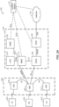
- FIG. 1 illustrates a high-level system architecture of a communications system 100 in accordance with an aspect of the disclosure.
- the communications system 100 contains UEs 1...N.
- the UEs 1...N can include cellular telephones, smartphones, tablet computers, personal digital assistant (PDAs), pagers, a laptop computer, a desktop computer, navigation devices, Internet of Things (IoT) devices, wearable devices (e.g., "smart" watches), and so on.
- PDAs personal digital assistant
- IoT Internet of Things
- wearable devices e.g., "smart" watches
- UEs 1...N are configured to communicate with an access network (e.g., the RAN 120, an access point 125, etc.) over a physical communications interface or layer, shown in FIG. 1 as air interfaces 104, 106, 108 and/or a direct wired connection.
- an access network e.g., the RAN 120, an access point 125, etc.
- a physical communications interface or layer shown in FIG. 1 as air interfaces 104, 106, 108 and/or a direct wired connection.
- the air interfaces 104 and 106 can comply with a given cellular communications protocol (e.g., Code Division Multiple Access (CDMA), Evolution-Data Optimized (EV-DO), Enhanced High Rate Packet Data (eHRPD), Global System for Mobile communications (GSM), Enhanced Data rates for GSM Evolution (EDGE), Wideband CDMA (WCDMA), LTE, etc.), while the air interface 108 can comply with a short range wireless protocol (e.g., IEEE 802.11).
- the RAN 120 includes a plurality of access points that serve UEs over air interfaces, such as the air interfaces 104 and 106.
- the access points in the RAN 120 can be referred to as "access nodes” or “ANs,” “access points” or “APs,” “base stations” or “BSs,” “Node Bs,” “eNodeBs” or “eNBs,” “New Radio NodeBs” or “gNBs,” and so on. These access points can be terrestrial access points (or ground stations), or satellite access points.
- the RAN 120 is configured to connect to a core network 140 that can perform a variety of functions, including connecting circuit switched (CS) and/or packet switched (PS) calls or sessions between UEs served by the RAN 120 and other UEs served by the RAN 120 or a different RAN altogether, and can also mediate an exchange of voice, data and/or other media between UEs served by the RAN 120 and other UEs and external networks such as Internet 175.
- the Internet 175 includes a number of routing agents and processing agents (not shown in FIG. 1 for the sake of convenience).
- UE N is shown as connecting to the Internet 175 directly (i.e., separate from the core network 140, such as over an Ethernet connection of WiFi or 802.11-based network).
- the Internet 175 can thereby function to connect packet-switched voice and data communications between UE N and UEs 1...N via the core network 140. Also shown in FIG. 1 is the access point 125 that is separate from the RAN 120. The access point 125 may be connected to the Internet 175 independently of the core network 140 (e.g., via an optical communication system such as FiOS, a cable modem, etc.).
- the air interface 108 may serve UE 4 or UE 5 over a local wireless connection, such as IEEE 802.11 in an example.
- a location server 170 is shown as connected to the Internet 175, the core network 140, or both.
- the location server 170 can be implemented as a plurality of structurally separate servers, or alternately may correspond to a single server.
- the location server 170 is configured to support one or more location services for UEs that can connect to the location server 170 via the core network 140 and/or the Internet 175.
- FIG. 2A illustrates an example configuration of the RAN 120 and a portion of the core network 140 of the communications system 100 based on an Evolved Packet System (EPS) or LTE network, in accordance with an aspect of the disclosure.
- the RAN 120 in the EPS / LTE network is configured with a plurality of eNodeBs 200, 205, and 210, which support LTE wireless access on air interface 104 and/or 106.
- the core network 140 includes a plurality of Mobility Management Entities (MMEs) 215 and 220, a Home Subscriber Server (HSS) 225, a Serving Gateway (SGW) 230 and a Packet Data Network Gateway (PDG) 235.
- MMEs Mobility Management Entities
- HSS Home Subscriber Server
- SGW Serving Gateway
- PGW Packet Data Network Gateway
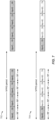
- FIG. 2A Network interfaces between these components, the RAN 120, the location server 170 and the Internet 175 are illustrated in FIG. 2A and are defined in Table 2 (below) as follows: Table 1 - EPS / LTE Core Network Connection Definitions Network Interface Description S1-MME Reference point for the control plane protocol between RAN 120 and MME 215. S1-U Reference point between RAN 120 and SGW 230 for the per bearer user plane tunneling and inter-eNodeB path switching during handover. S5 Provides user plane tunneling and tunnel management between SGW 230 and PDG 235. It is used for SGW relocation due to UE mobility and if the SGW 230 needs to connect to a non-collocated PDG for the required Packet Data Network (PDN) connectivity.
- PDN Packet Data Network
- S6a Enables transfer of subscription and authentication data for authenticating/authorizing user access to the evolved system (Authentication, Authorization, and Accounting (AAA) interface) between MME 215 and HSS 225.
- AAA Authentication, Authorization, and Accounting
- S8 Inter-PLMN reference point providing user and control plane between the SGW 230 in a Visited Public Land Mobile Network (VPLMN) and the PDG 235 in a Home Public Land Mobile Network (HPLMN).
- S8 is the inter-PLMN variant of S5.
- the packet data network may be an operator external public or private packet data network or an intra-operator packet data network (e.g., for provision of Internet Protocol (IP) Multimedia Subsystem (IMS) services).
- IP Internet Protocol
- IMS Internet Multimedia Subsystem
- E-SMLC Enhanced Serving Mobile Location Center
- FIG. 2A A high-level description of the components shown in FIG. 2A will now be provided. However, these components are each well-known in the art from various 3GPP Technical Specifications (TSs), such as TS 23.401, and the description contained herein is not intended to be an exhaustive description of all functionalities performed by these components.
- TSs 3GPP Technical Specifications
- the eNodeBs 200, 205, and 210 are configured to provide LTE and/or NB-IoT radio access to UEs (e.g., any of UEs 250, 252, and 254) and to provide signaling and voice/data connectivity between any UE and elements in core network 140, such as MME 215 and SGW 230.
- UEs e.g., any of UEs 250, 252, and 254
- MME 215 and SGW 230 e.g., MME 215 and SGW 230.
- the eNodeBs 200, 205, and 210 may also be configured to broadcast PRS to nearby UEs to enable any UE to make measurements of PRS timing differences between pairs of eNodeBs and thereby enable a location estimate of the UE to be obtained by the UE itself or by a location server (e.g., location server 170) to which the timing difference measurements may be sent using OTDOA positioning.
- a location server e.g., location server 170
- location estimate is used herein to refer to an estimate of a location for a UE (e.g., any of UEs 250, 252, and 254), which may be geographic (e.g., may comprise a latitude, longitude, and possibly altitude) or civic (e.g., may comprise a street address, building designation, or precise point or area within or nearby to a building or street address, such as a particular entrance to a building, a particular room or suite in a building, or a landmark such as a town square).
- a location estimate may also be referred to as a "location,” a "position,” a “fix,” a "position fix,” a “location fix,” a "position estimate,” a “fix estimate,” or the like.
- the means of obtaining a location estimate may be referred to generically as "positioning,” “locating,” “position fixing,” or the like.
- a particular solution for obtaining a location estimate may be referred to as a “location solution” or the like.
- a particular method for obtaining a location estimate as part of a location solution may be referred to as a "position method,” a “positioning method,” or the like.
- the MMEs 215, and 220 are configured to support network attachment of UEs (e.g., UEs 250, 252, and 254), mobility of UEs, and bearer assignment to UEs.
- MME functions include: Non-Access Stratum (NAS) signaling to UEs, NAS signaling security, mobility management for inter- and intra-technology handovers of UEs, PDG and SGW selection, and MME selection for UE handovers with MME change.
- NAS Non-Access Stratum
- the SGW 230 is the gateway that terminates the user plane interface toward the RAN 120.
- the functions of the SGW 230 include: mobility anchor point, packet routing and forwarding, and transport level packet marking in the uplink and the downlink (e.g., setting the DiffServ Code Point (DSCP) based on a Quality of Service (QoS) Class Identifier (QCI) of an associated EPS bearer).
- DSCP DiffServ Code Point
- QoS Quality of Service
- QCI Quality of Service Class Identifier
- the PDG 235 is the gateway that terminates the SGi user plane interface toward the PDN, e.g., the Internet 175. If a UE is accessing multiple PDNs, there may be more than one PDG for that UE.
- PDG 235 functions include: packet filtering (e.g., using deep packet inspection), UE IP address allocation, transport level packet marking in the uplink and downlink (e.g., setting the DSCP based on the QCI of an associated EPS bearer), accounting for inter operator charging, uplink (UL) and downlink (DL) bearer binding, UL and DL rate enforcement and service level rate enforcement, and UL bearer binding.
- the PDG 235 may provide PDN connectivity to both GSM/EDGE Radio Access Network (GERAN) / Universal Terrestrial Radio Access Network (UTRAN)-only UEs, and Enhanced UTRAN (E-UTRAN)-capable UEs using any of E-UTRAN, GERAN, or UTRAN.
- the PDG 235 may provide PDN connectivity to E-UTRAN-capable UEs using E-UTRAN only over the S5/S8 interface.
- the location server 170 is shown as connected to one or more of the Internet 175, the PDG 235, MME 220, and MME 215.
- the connections to MME 215 and MME 220 are applicable when location server 170 is or contains an E-SMLC.
- the connections to the Internet 175 and/or to the PDG 235 are applicable when location server 170 is or contains an SLP, such a Home SLP (H-SLP), Emergency SLP (E-SLP), or Discovered SLP (D-SLP).
- H-SLP Home SLP
- E-SLP Emergency SLP
- D-SLP Discovered SLP
- Location server 170 may be used (i) to obtain a location for any of UEs 250, 252, and 254 (e.g., from signal measurements obtained and transferred by any of UEs 250, 252, and 254) and/or (ii) to provide assistance data to any of UEs 250, 252, and 254 to enable any of UEs 250, 252, and 254 to acquire and measure signals (e.g., signals from one or more of eNodeBs 200, 205, and 210) and, in some cases, compute a location from these signal measurements.
- signals e.g., signals from one or more of eNodeBs 200, 205, and 210
- assistance data can be orbital and timing data for Global Positioning System (GPS) or other Global Navigation Satellite System (GNSS) satellites when GPS or GNSS positioning is used, or information concerning downlink transmission from eNodeBs nearby to a UE (e.g., any of eNodeBs 200, 205, and 210) when OTDOA is used for positioning.
- GPS Global Positioning System
- GNSS Global Navigation Satellite System
- core network 140, RAN 120, and location server 170 in FIG. 2A may correspond, respectively, to core network 140, RAN 120, and location server 170 in FIG. 1 .
- UEs 250, 252, and 254 in FIG. 2A may each correspond to any of UEs 1 to N in FIG. 1 .
- FIG. 2B is a high-level diagram showing additional features of the communications system 100 discussed above with reference to FIG. 2A .
- the location server 170 may include an E-SMLC 172, a Gateway Mobile Location Center (GMLC) 174, and an SLP 176.
- FIG. 2B also illustrates the type of communications between various components. For example, communications between the eNodeB 200/205/210, the SGW 230, the PDG 235, and the SLP 176 may support a user plane location solution, while communications between the eNodeB 200/205/210, the MME 215/220, and the E-SMLC 172 and/or the GMI,C 174 may support a control plane location solution.
- GMLC Gateway Mobile Location Center
- This disclosure utilizes the Observed Time Difference Of Arrival (OTDOA) positioning method which is defined by the 3rd Generation Partnership Project (3GPP) (e.g., in 3GPP Technical Specification (TS) 36.355) for wireless networks that provide wireless access using LTE.
- 3GPP 3rd Generation Partnership Project
- TS Technical Specification
- OTDOA is a multilateration method in which the UE measures the time difference, known as a Reference Signal Time Difference (RSTD), between specific reference signals (e.g., PRS) from different pairs of eNodeBs and either reports these time differences to a location server, such as the E-SMLC 172 or SLP 176, or computes a location itself from these time differences.
- RSTD Reference Signal Time Difference
- RSTDs are measured between a reference cell and one or more neighbor cells.
- the reference cell remains the same for all RSTDs measured by a UE for any single positioning use of OTDOA and would typically correspond to the serving cell for the UE or another nearby cell with good signal strength at the UE.
- the neighbor cells would normally be supported by eNodeBs different from the eNodeB for the reference cell and may have good or poor signal strength at the UE.
- the location computation can be based on the measured time differences (e.g., RSTDs) and knowledge of the eNodeBs' locations and relative transmission timing (e.g., regarding whether eNodeBs are accurately synchronized or whether each eNodeB transmits with some known time difference relative to other eNodeBs).
- RSTDs measured time differences
- eNodeBs' locations and relative transmission timing e.g., regarding whether eNodeBs are accurately synchronized or whether each eNodeB transmits with some known time difference relative to other eNodeBs.
- the necessary additional data may be provided to the UE by a location server (e.g., E-SMLC 172 or SLP 176).
- a location estimate for a UE may be obtained (e.g., by the UE itself or by a location server) from OTDOA measured time differences and from other measurements made by the UE (e.g., measurements of signal timing from GPS or other GNSS satellites).
- the OTDOA measurements may contribute towards obtaining a UE location estimate but may not wholly determine the location estimate.
- a typical positioning signaling flow may start with the MME 215/220 initiating a location service or receiving a location service request from the UE 250/252/254 or GMI,C 174.
- the GMI,C 174 is the first node with which an external Location Based Service (LBS) client communicates.
- LBS Location Based Service
- the MME 215/220 sends a positioning request to the location server 170, specifically, the E-SMLC 172.
- the E-SMI,C 172 processes the request, communicates with the UE 250/252/254, and requests RSTD measurements from the UE 250/252/254.
- the E-SMLC 172 Upon receiving RSTD measurements from the UE 250/252/254, the E-SMLC 172 estimates the position of the UE 250/252/254 and sends the result back to the MME 215/220. The MME 215/220 may further forward the result to the UE 250/252/254 or the GMI,C 174 as appropriate.
- FIG. 3A illustrates an exemplary frame structure 300 in LTE and 5G NR.
- a radio frame having a length of 10 milliseconds (ms) is composed of 10 subframes having a length of 1 ms each.
- Each subframe e.g., subframe 302
- a subframe 302 is composed of 12 subcarriers, and in the time domain, a subframe 302 is composed of seven symbols.
- One symbol on one subcarrier is referred to as a physical resource block (PRB).
- PRB physical resource block
- PRS are transmitted in predefined positioning subframes grouped by several consecutive subframes N PRS , which are referred to as "positioning occasions" or “PRS occasions.” Positioning occasions occur periodically with a certain periodicity T PRS .
- the period T PRS can be 160, 320, 640, or 1280 subframes (or milliseconds), and the number of consecutive subframes NPRS can be one, two, four, or six subframes.
- Each eNodeB can configure a subframe offset, which defines the starting subframe for PRS transmission relative to the start of a system frame cycle.
- the PRS sequence is a pseudo-random Quadrature Phase Shift Keying (QPSK) sequence.
- QPSK Quadrature Phase Shift Keying
- the parameter used to initialize a PRS sequence depends on the orthogonal frequency-division multiplexing (OFDM) symbol index, slot index, and physical cell identity. As such, the sequence varies with the OFDM symbol index, slot index, and physical cell identity. Given an initialization parameter, a PRS sequence can be generated. The complex-valued QPSK elements of the sequence are then mapped to resource elements determined by physical cell identity.
- the overall time-frequency PRS mapping pattern is a diagonal pattern, as illustrated in FIG. 3B .
- FIG. 3B illustrates a subframe 302 having a PRS mapping pattern of in-band PRS for one and two Physical Broadcast Channel (PBCH) antenna ports.
- the subframe 302 may be a subframe in LTE or 5G NR.
- subframe 302 has a length of one subframe (which may have a length of 1 ms) that is divided into two slots (which may have a length of 0.5 ms).
- one OFDM symbol on one subcarrier is referred to as a PRB.
- a PRB is also referred to as a resource element (RE).
- RE resource element
- PRS has a frequency reuse factor of six.
- a frequency reuse factor of six means that there are six distinct pairs of frequency tones that can be used as PRS in each OFDM symbol (e.g., ⁇ 0, 6 ⁇ , ⁇ 1,7 ⁇ , ..., ⁇ 5,11 ⁇ ). Some OFDM symbols may share the same tone-pairs.
- the OFDM symbol index ( l ) may have a value from 0 to 6, and each resource block (e.g., PRB 302) may consist of 12 subcarriers with a subcarrier spacing of 15 kHz. As shown in FIG. 3B , only two of the 12 resource elements per symbol index are used by PRS.
- PRS sequences are generated as the time (i.e., OFDM symbol index and slot index) varies, with each sequence mapped in frequency to the corresponding resource elements.
- the first three OFDM symbols in a subframe are not used by PRS signals since they may be used by other LTE signals, such as the Physical Downlink Control Channel (PDCCH).
- the other OFDM symbols not used by PRS can be used by LTE Cell-specific Reference Signals (CRS).
- NB-IoT Narrowband IoT
- MTC Machine Type Communication
- NB-IoT Narrowband IoT
- PRS in NB-IoT are referred to as Narrowband Positioning Reference Signals (NPRS).
- NPRS Narrowband Positioning Reference Signals
- PRS may refer to either or both PRS and NPRS, depending on the context.
- FIG. 4 illustrates example PRS configurations 400 for support of OTDOA within a single cell or within a plurality of associated cells.
- PRS configurations 400 in FIG. 4 may be based, at least in part, on PRS transmission for LTE as defined in 3GPP TS 36.211.
- a single cell may comprise a single narrow bandwidth cell supporting 200 KHz carrier bandwidth.
- a plurality of associated cells may comprise one or more narrow bandwidth cells each supporting 200 KHz carrier bandwidth, where all the associated cells in the plurality use the same carrier frequency, are supported by the same eNodeB, and have approximately the same coverage areas (e.g., share a common geographic coverage area), and where each narrow bandwidth cell may have an additional frequency offset.
- a plurality of two or more associated cells as just described is referred to herein as a "cell set.”
- a single reference cell or a single neighbor cell would need to support at least 10 MHz carrier bandwidth, whereas a reference cell set or neighbor cell set would need to include one wide bandwidth cell supporting at least 10 MHz carrier bandwidth.
- PRS configurations 400 in FIG. 4 comprise a number of PRS positioning occasions for two different PRS carrier bandwidth values - 10 MHz and 200 KHz.
- Each PRS positioning occasion in the example of FIG. 4 comprises consecutive LTE subframes (e.g., "SF1," "SF2") and occurs at different fixed periodic intervals.
- the series of LTE subframes (referred to herein as PRS subframes) containing PRS signals that are transmitted for the cell or cell set are represented horizontally in FIG. 4 , with later subframes shown to the right of earlier subframes.
- the PRS bandwidth for each PRS subframe is represented vertically in FIG. 4 with higher PRS bandwidth occupying greater vertical extent.
- PRS configurations 400 include a series of PRS positioning occasions.
- a first PRS positioning occasion 406 includes a number (N PRS ) of consecutive PRS subframes 402-1 (e.g., two) that have 10 MHz PRS carrier bandwidth and fixed PRS periodicity T PRS .
- PRS configuration 400 further includes a number (N PRS ) of consecutive PRS subframes 404-1 (e.g., two) that have 200 KHz PRS carrier bandwidth and a fixed periodicity.
- N PRS consecutive PRS subframes 404-1 (e.g., two) that have 200 KHz PRS carrier bandwidth and a fixed periodicity.
- At the end of the first PRS positioning occasion 406, but before the end of the PRS period T PRS there is a subsequent set of PRS subframes 404-2 that have 200 KHz PRS carrier bandwidth.
- the sequence repeats, with a second sequence of consecutive PRS subframes 402-2 and a third and fourth sequence of consecutive PRS subframes 404-3 and 404-4
- FIG. 4 only shows a few PRS positioning occasions transmitted by the cell or cell set over any complete sequence of 1024 LTE system frames. Additional PRS positioning occasions not shown in FIG. 4 may be present that could be represented to the left and/or right of FIG. 4 if additional space were available.
- 10 MHz PRS carrier bandwidth may correspond to 9 MHz of usable (occupied) PRS bandwidth
- 200 KHz PRS carrier bandwidth may correspond to 180 KHz of usable (occupied) PRS bandwidth.
- a UE e.g., UE 250
- location server e.g., location server 170
- PRS configuration parameters for each of the PRS configurations 400 include the PRS bandwidth, the periodicity of consecutive PRS positioning occasions, the number of consecutive PRS subframes in each PRS positioning occasion (which is two in each case in this example), and the subframe offset of the first PRS positioning occasion for each PRS configuration.
- Other PRS configuration parameters not explicitly shown in FIG. 4 could include one or more of the radio frame offset, a PRS code sequence, a PRS frequency shift, a PRS muting pattern, and a PRS direction of transmission (e.g., when a PRS is beamformed by an eNodeB in a particular direction using a multiple antenna array).
- NPRS is configured per NB-IoT carrier transmitting NPRS.
- Each NB-IoT carrier can have different configuration parameters, Part A and Part B.
- the network e.g., location server 170
- Part A uses a bitmap to indicate the NPRS subframes in one NPRS positioning occasion.
- the value of each bit indicates the presence of NPRS in the corresponding subframe.
- the length of the NPRS bitmap is the same length as the bitmap of valid subframe configurations in LTE (i.e., 10 or 40 bits).
- the bitmap of valid subframe configurations allows the network to reserve some subframes for other purposes, and the set of subframes that are indicated invalid are not used for transmission to NB-IoT UEs. Since legacy NB-IoT UEs do not understand NPRS transmissions, the subframes containing NPRS are marked as invalid downlink subframes in the bitmap of valid subframe configuration.
- the NPRS subframes indicated with Part A occur in every radio frame without any long-term periodicity.
- the length of the NPRS bitmap may be considered as the period of NPRS positioning occasions.
- Each NPRS period can be regarded as a positioning occasion, and the subframes used for NPRS are indicated in the NPRS bitmap. With this indication, the NPRS subframes in a positioning occasion need not be consecutive, while the PRS subframes of a positioning occasion in LTE are always consecutive.
- Part B is similar to LTE PRS and specifies the periodicity of positioning occasions, the number of consecutive NPRS subframes in a positioning occasion, and the NPRS subframe offset. Unlike Part A, NPRS subframes indicated with Part B do not have to be invalid subframes.
- the periodicity of NPRS occasion is still 160, 320, 640, or 1280, but the size of the NPRS subframe offset is limited to reduce the overhead of the LPP assistance data transfer.
- the NPRS subframe offset is a * T PRS , where a takes the value of 0, 1/8, 2/8, 3/8, 4/8, 5/8, 6/8, or 7/8 and the number of consecutive NPRS subframes may be 10, 20, 40, 80, 160, 320, 640, or 1280. Consequently, the consecutive NPRS transmissions in a positioning occasion can be much longer than their counterparts in both LTE and LTE-M OTDOA. This longer NPRS transmission partially compensates for the reduced bandwidth of NPRS.
- Part A and Part B may both be configured. In that case, a subframe contains NPRS if both parts of the configuration indicate that the subframe contains NPRS.
- 3GPP TS 36.211 Release 14 introduced an OTDOA-based positioning for NB-IoT that specifies that an NB-IOT UE be able to perform a location determination based on PRS transmitted during a single PRB (illustrated in FIG. 3 ), instead of PRS transmitted during consecutive subframes (as discussed with reference to FIG. 4 ).
- the underlying PRS sequence design in NB-IoT remains largely the same as in wideband LTE, except for some increase in the number of resource elements in the guardband / standalone deployment.
- NB-IoT positioning generally suffers from poor accuracy due to insufficient processing gain. More specifically, NB-IoT utilizes only 14 to 28 resource elements for in-band / guardband / standalone, whereas LTE (operating at 20 MHz) utilizes 1400 resource elements, making it more difficult for the NB-IoT UE to calculate the appropriate gain for the PRS measurements. As such, it can take up to 320 NPRS subframes to achieve RSTD accuracy of approximately 20 time units (Ts) in normal coverage areas for non-colliding PRS.
- Ts time units
- the poor cross-correlation property due to the short PRS sequence length also makes the NB-IoT UE vulnerable to detecting false peaks from colliding PRS, even after observing a large number of NPRS subframes, as the false peak magnitude decreases exponentially with the length of the PRS sequence.
- a false peak from a PRS collision can occur when, for example, an NB-IoT UE measures the received time of a PRS from a first cell "A" that transmits a first PRS sequence "A,” and the received time of a PRS from a second cell “B” that transmits a second PRS sequence "B” on the same resource element (RE).
- RE resource element
- FIG. 5 illustrates a comparison between the colliding and non-colliding PRS scenarios for different coverages.
- Table 502 illustrates colliding and non-colliding PRS scenarios for "normal" coverage, e.g., a SINR of greater than or equal to -6dB.
- Table 504 illustrates colliding and non-colliding PRS scenarios for "enhanced” coverage, e.g., a SINR less than -6dB and greater than or equal to -15dB.
- These tables show the vulnerability of existing NPRS sequence design to the colliding PRS scenario (due to the poor cross-correlation property). More specifically, for the same number of NPRS subframe observations and the same effective SINR conditions, RSTD measurement accuracy is substantially worse in the colliding PRS scenario.
- NPRS' are only transmitted in resource blocks for NB-IoT carriers configured for NPRS transmission.
- the starting positions of the OFDM symbols configured for NPRS transmission are identical to those in a subframe in which all OFDM symbols have the same cyclic prefix length as the OFDM symbols configured for NPRS transmission.
- n s is the slot number within a radio frame
- l is the OFDM symbol number within the slot
- c ( i ) is the pseudo-random sequence.
- the gold sequence on each OFDM symbol containing PRS is of length two (i.e., spanning two non-adjacent subcarriers per symbol of a PRB, as illustrated in FIG. 3B ) due to the single PRB transmission. This leads to a poor cross-correlation property in the colliding PRS scenario.
- the initial seed for the PRS sequence changes every symbol, and resets every radio frame. As such, there may not be enough averaging across symbols to suppress the false peaks.
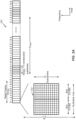
- FIG. 6 illustrates differences between conventional PRS transmissions in wideband and NPRS in narrowband.
- Time diagram 602 illustrates an exemplary conventional wideband PRS transmission scenario that has a gold sequence of length 2x50.
- Time diagram 604 illustrates an exemplary conventional NPRS transmission scenario that has a gold sequence of length two.
- RF radio frame
- 10 ms consists of 10 subframes and 20 slots.
- the slot number Ns cycles from 0 to 19 over the span of 10 subframes, or one radio frame.
- the effective sequence length in NPRS transmission increases by employing higher PRS sequence diversity across time.
- the PRS sequences across different radio frames can be changed when PRS is transmitted over narrowband.
- a false peak position from the poor cross correlation in a certain PRS sequence pair can therefore be suppressed by averaging over a large number of different PRS sequence pairs.
- This can be realized by resetting the slot number used for computing the initial seed ( c init ) every K (e.g., greater than one) radio frames.
- the actual NPRS sequence periodicity can be configurable / signaled to the narrowband-capable UE as a part of PRS configuration.
- c init 2 28 ⁇ ⁇ N ID NPRS / 512 ⁇ + 2 10 ⁇ 7 ⁇ n s + 1 + l + 1 ⁇ 2 ⁇ N ID NPRS mod512 + 1 + 2 ⁇ N ID NPRS mod512 + N CP
- N ID NPRS is fixed for each cell, and only n s and l change across different slots / symbols.
- NPRS diversity is implemented by changing the PRB index (m) used for sequence generation at each radio frame.
- PRB index (m) used for sequence generation at each radio frame.
- n s m 1 2 1 ⁇ 2 ⁇ c 2 m + j 1 2 1 ⁇ 2 ⁇ c 2 m + 1
- m 0,1 , ... , 2 N RB max ,DL ⁇ 1
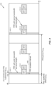
- FIG. 7 illustrates an example of increasing NPRS sequence diversity using the proposed slot number extension, according to an example useful for understanding the invention.
- Time diagram 702 illustrates the conventional NPRS sequencing, in which the slot number (Ns) resets every 10 ms, or every radio frame ("RF" in the figure). Note that a 10 ms time period, or one radio frame, consists of 10 subframes and 20 slots (as each subframe has a length of 1 ms and each subframe has two 0.5 ms slots). Hence, the slot number Ns cycles from 0 to 19 over the span of 10 subframes, or one radio frame, and then resets.
- Time diagram 704 illustrates the increased PRS sequence diversity of the present disclosure.
- Ns the slot number (Ns) resets every 40ms, rather than every 10ms.
- Ns cycles from 0 to 79 (i.e., 80 slots), instead of from 0 to 19 (i.e., 20 slots), over the span of four radio frames (or 40ms), instead of one, and then resets.
- FIG. 7 illustrates PRS diversity based on the slot number extension, as shown below with reference to FIG. 9 , depicting an example according to the invention, it is equally applicable to the alternative option based on the PRB index (m) extension.
- FIG. 8 illustrates the differences between conventional wideband PRS transmissions and NPRS transmissions utilizing the slot number extension disclosed herein according to an example useful for understanding the invention.
- Time diagram 804 illustrates an exemplary NPRS transmission scenario according to the present disclosure that has a gold sequence of length two.
- NPRS are transmitted on the same PRB using a different NPRS sequence across different symbols/subframes/radio frames.
- PRS sequence diversity is achieved across the time domain.
- FIG. 9 illustrates an example of NPRS transmissions utilizing the PRB index extension disclosed herein which is according to the invention.
- Time diagram 902 like time diagram 602 in FIG. 6 , illustrates an exemplary conventional wideband PRS transmission scenario that has a gold sequence of length 2x50.
- Time diagram 904 illustrates an exemplary NPRS transmission scenario according to the present disclosure that has a gold sequence of length two. In the illustrated scenario, at every kth radio frame of the NPRS transmissions, the kth PRB portion of the wideband PRS sequence is used as the corresponding NPRS sequence.
- the PRB index resets every four radio frames, or 40 ms.
- the NPRS sequence may be longer or shorter than four radio frames. In either case, the NPRS sequence will transmitted on the PRB having the index of the corresponding wideband PRS.
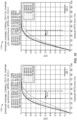
- FIG. 10 illustrates exemplary simulation results of colliding PRS in "enhanced" coverage (e.g., a SINR less than -6dB and greater than or equal to -15dB) according to an aspect of the disclosure.
- a PRS sequence periodicity of 160 ms provides approximately a 15 Ts 90-percentile RSTD accuracy improvement. That is, at 90-percentile RSTD accuracy, there is a reduction from 45 Ts to 30 Ts for neighbor cell 1.
- the NPRS could be a part of the wideband PRS transmission, which would not use the proposed longer PRS sequence periodicity.
- the eNodeB can fall back to the legacy PRS diversity sequence at the NPRS occasion(s) coinciding with the wideband PRS occasion(s).
- an NB-IoT UE supporting the proposed longer PRS sequence periodicity would be provided with both the NPRS and the wideband PRS configuration so that it can use the appropriate PRS sequence at each NPRS/PRS occasion.
- the NPRS slot number could reset at every wideband PRS occasion.
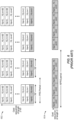
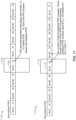
- FIG. 11 illustrates these two options for addressing backward compatibility issues with wideband PRS.
- time diagram 1102 illustrates the first option, which is useful for understanding the invention, where only the slot numbers (Ns) for the NPRS occasion 1106 coinciding with the wideband PRS occasion 1104 are overridden.
- the slot numbers are not, however, reset.
- the slot numbers (Ns) 60 to 79 of the NPRS occasion 1106 are overridden with the slot numbers (Ns) 0 to 19 (i.e., the slot numbers of the legacy NPRS diversity sequence). Because the slot numbers are not reset, however, the next slot numbers for the next NPRS occasion continue the previous pattern, and are therefore slot numbers (Ns) 0 to 19.
- Time diagram 1110 illustrates the second option, where the slot numbers (Ns) for the NPRS occasion 1114 coinciding with the wideband PRS occasion 1112 are reset.
- the slot numbers (Ns) 60 to 79 of the NPRS occasion 1114 are overridden with the slot numbers (Ns) 0 to 19 (i.e., the slot numbers of the legacy NPRS diversity sequence). Because the slot numbers are reset, the slot numbers of the following NPRS occasion continue this numbering, and are therefore numbered 20 to 39.
- legacy NB-IoT UEs may not understand or support the new NPRS sequence periodicity.
- NPRS transmissions using the legacy (shorter) NPRS sequence can be embedded in the proposed NPRS transmission sequence.
- a legacy NB-IoT UE can be directed to use only a fraction of the NPRS occasions that employ the legacy PRS sequences, while an NB-IoT UE supporting the longer PRS sequences can be directed to use the entire NPRS occasion.
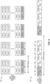
- FIG. 12 illustrates a timing diagram 1200 in which legacy NPRS transmission sequences are embedded in the proposed NPRS transmission sequences.
- a first NPRS period includes three NPRS subframes 1202 (having slot numbers (Ns) 0 to 19), 1204 (having slot numbers (Ns) 20 to 39), and 1206 (having slot numbers (Ns) 40 to 59), all of which are usable by an NB-IoT UE configured to detect an extended NPRS sequence as described herein.
- the first subframe i.e., NPRS subframe 1202 having slot numbers (Ns) 0 to 19, would be usable by a legacy NB-IoT UE, as this subframe includes the legacy PRS diversity sequence.
- NPRS transmissions based on short (legacy) and extended NPRS sequences can be multiplexed in time.
- the location server e.g., location server 170
- the actual NPRS subframe duration of each PRS sequence length could remain configurable, depending on the number of NB-IoT UEs supporting short and long PRS sequence lengths within the network.
- Legacy NB-IoT UEs would receive only the legacy NPRS configuration, while UEs configured to detect the longer PRS sequences may optionally receive both.
- the starting slot number for a new NPRS transmission can be either 0 or set based on the subframe offset from the beginning of the NPRS period. In either case, the UE should signal its capability to support the new PRS sequence length to the location server.
- FIG. 13 illustrates a timing diagram 1300 in which legacy NPRS transmission sequences are multiplexed with the proposed NPRS transmission sequences.
- a first NPRS period includes a legacy NPRS transmission sequence 1302 comprising two subframes each having slot numbers (Ns) 0 to 19.
- the NPRS period also includes a long NPRS transmission sequence 1304 comprising three subframes.
- the first subframe has slot numbers (Ns) 0 to 19
- the second has slot numbers (Ns) 20 to 39
- the third has slot numbers (Ns) 40 to 59.
- a legacy NB-IoT UE would be able to use the legacy NPRS transmission sequence 1302, and an NB-IoT UE capable of detecting the extended NPRS transmission sequences described herein would be able to use either the legacy NPRS transmission sequence 1302 or the long NPRS transmission sequence 1304.
- FIG. 14 illustrates an exemplary method 1400 for generating and transmitting extended NPRS sequences according to the invention.
- the method 1400 may be performed by an eNodeB (e.g., eNodeB 200/205/210) or other network element (e.g., location server 170, E-SMLC 172, SLP 176, GMI,C 174).
- the method 1400 may be performed in real-time, as PRS are transmitted by the eNodeB, or in advance (e.g., by the location server 170, E-SMLC 172, SLP 176, GMI,C 174) to determine how PRS should be transmitted by the eNodeB.
- the method 1400 determines whether or not the current time slot is the beginning of a new NPRS period. If it is not, the method 1400 waits until it is. At 1406, if it is the beginning of a new NPRS period, the method 1400 sets k to 0, l to 0, and n s to 0.
- the method 1400 determines whether or not the l th OFDM symbol in the n s th timeslot is for PRS transmission (i.e., whether PRS is to be transmitted on the OFDM symbol l of the n s th timeslot). If it is not, then at 1410, the method 1400 continues to the next OFDM symbol and updates l and n s .
- the method 1400 determines whether or not wideband PRS is transmitted in the same symbol. If it is not, then at 1414, the method 1400 transmits the NPRS sequence s k ( n s ,l ) in a single PRB (i.e., the PRB assigned for the NPRS transmission of the NB-IoT cell). In that way, the NPRS sequence is transmitted on different slot / symbol combinations of the same PRB. Said another way, NPRS are transmitted on the same PRB using a different NPRS sequence across different symbols / subframes / radio frames. If, however, wideband PRS is transmitted in the same symbol, then at 1416, the method 1400 transmits the wideband PRS sequence across all PRBs (as illustrated in FIG. 11 ).
- the method 1400 determines whether the current OFDM symbol is the last symbol of the last NPRS subframe of the current NPRS period. If it is, the method 1400 returns to 1404. If it is not, however, then at 1420, the method 1400 determines whether or not it is the end of a radio frame. If it is not, the method 1400 returns to 1410. If it is, however, then at 1422, the method 1400 increments k by 1 to switch to the next NPRS sequence set, and the method 1400 returns to 1410.
- FIG. 15 shows an exemplary signaling flow 1500 illustrating the LPP protocol useful for understanding the invention.
- LPP is used between the location server (e.g., location server 170) and the UE (e.g., UE 250/252/254).
- the illustrated LPP protocol can be used to communicate a UE's ability to measure an extended NPRS sequence as described herein.
- positioning of the UE 250/252/254 is supported via an exchange of LPP messages between the UE 250/252/254 and the location server 170 (e.g., the E-SMLC 172 or SLP 176).
- the LPP messages may be exchanged between the UE 250/252/254 and the location server 170 via one or more intermediate networks, such as RAN 120 (e.g., via eNodeB 200/205/210) and core network 140 (e.g., via MME 215 with a control plane location solution when location server 170 comprises E-SMLC 172 or via PDG 235 and SGW 230 with a user plane location solution when location server 170 comprises SLP 176).
- the LPP messages and the procedures that they support are described in 3GPP TS 36.355.
- the procedure shown in FIG. 15 may be used to position the UE 250/252/254 in order to support various location-related services, such as navigation for UE 250/252/254 (or for the user of UE 250), or for routing, or for other location services.
- the UE 250/252/254 may receive a request for its positioning capabilities from the location server 170 at stage 1502 (e.g., an LPP Request Capabilities message).
- the UE 250/252/254 provides its positioning capabilities to the location server 170 relative to the LPP protocol by sending an LPP Provide Capabilities message to location server 170 indicating the position methods and features of these position methods that are supported by the UE 250/252/254 using LPP.
- the capabilities indicated in the LPP Provide Capabilities message may, in some aspects, indicate that the UE 250/252/254 supports OTDOA positioning and may indicate the capabilities of the UE 250/252/254 to support OTDOA.
- the UE 250/252/254 can include (N)PRS capability parameters describing supported (N)PRS configurations for OTDOA in the LPP Provide Capabilities message.
- the (N)PRS capability parameters can indicate the ability of the UE 250/252/254 to detect and measure an extended NPRS sequence as described herein.
- the location server 170 determines to use an extended NPRS sequence for OTDOA based on the indicated UE 250/252/254 support for OTDOA and the extended NPRS sequence at stage 1504.
- the location server 170 determines a reference cell and neighbor cells (or a reference cell set and/or neighbor cell sets) for OTDOA based at least in part on the (N)PRS capability parameters received at stage 1504.
- the location server 170 may further determine (e.g., according to the method 1400 illustrated in FIG.
- the location server 170 then sends an LPP Provide Assistance Data message to the UE 250/252/254 at stage 1508.
- the LPP Provide Assistance Data message at stage 1508 may be sent by the location server 170 to the UE 250/252/254 in response to an LPP Request Assistance Data message sent by the UE 250/252/254 to the location server 170 (not shown in FIG. 15 ).
- the LPP Provide Assistance Data message may include positioning assistance data in the form of OTDOA assistance data to enable or to help enable the UE 250/252/254 to obtain and return OTDOA RSTD measurements, and may include information for the reference cell (or reference cell set) identified at stage 1506 (e.g., corresponding to one of eNodeBs 200, 205, 210).
- the information for the reference cell may include a global ID for the reference cell (or a global ID for each cell in a reference cell set), a physical cell ID for the reference cell (or a physical cell ID for each cell in reference cell set), carrier frequency information, and PRS configuration parameters for the PRS configurations determined for the reference cell (or reference cell set) at stage 1506 (e.g., PRS bandwidth, PRS carrier frequency, number of subframes per PRS positioning occasion, PRS code sequence, starting point and periodicity of PRS positioning occasions, PRS direction of transmission and/or muting sequence).
- PRS configuration parameters for the PRS configurations determined for the reference cell (or reference cell set) at stage 1506 (e.g., PRS bandwidth, PRS carrier frequency, number of subframes per PRS positioning occasion, PRS code sequence, starting point and periodicity of PRS positioning occasions, PRS direction of transmission and/or muting sequence).
- the LPP Provide Assistance Data message may also include OTDOA assistance data for neighbor cells (and/or neighbor cell sets) identified at stage 1506 (e.g., corresponding to one or more of eNodeBs 200, 205, 210).
- the information provided for each neighbor cell (and/or each neighbor cell set) in the LPP Provide Assistance Data message may be similar to that provided for the reference cell (e.g., may include a cell ID, cell frequency, and PRS configuration parameters for the PRS configurations determined at stage 1506) and may further include, for example, a slot number and/or subframe offset between the neighbor cell (or neighbor cell set) and the reference cell (or reference cell set), and/or an expected approximate RSTD value and RSTD uncertainty.
- the PRS configuration parameters provided by the location server for the reference cell (or reference cell set) and each neighbor cell (or neighbor cell set) at stage 1508 may be as described in association with FIGS. 7-9 and 11-13 .
- the location server 170 sends a request for location information to the UE 250/252/254.
- the request may be an LPP Request Location Information message.
- the LPP Provide Assistance Data message sent at stage 1508 may be sent after the LPP Request Location Information message at 1510 - e.g., if UE 250/252/254 sends a request for assistance data to location server 170 (e.g., in an LPP Request Assistance Data message, not shown in FIG. 15 ) after receiving the request for location information at stage 1510.
- the request for location information sent at stage 1510 may request the UE 250/252/254 to obtain RSTD measurements for OTDOA - e.g., in association with the information for the reference cell (or reference cell set), neighbor cells (and/or neighbor cell sets) and PRS configuration parameters sent to UE 250/252/254 at stage 1508.
- the UE 250/252/254 utilizes the OTDOA positioning assistance information received at stage 1508 and any additional data (e.g., a desired location accuracy or a maximum response time) received at stage 1510 to perform RSTD measurements for the OTDOA position method.
- the RSTD measurements may be made between the reference cell (set) indicated at stage 1508, or a reference cell (or reference cell set) determined by the UE from the neighbor cells (and/or neighbor cell sets) indicated at stage 1508, and one or more of the (other) neighbor cells (and/or neighbor cell sets) indicated at stage 1508.
- the UE 250/252/254 utilizes the PRS configuration parameters for the reference and neighbor cells (and/or cell sets) provided at stage 1508 to acquire and measure PRS signals for these cells (e.g., NPRS of an extended NPRS sequence as described herein), and according to the PRS configurations supported by UE 250/252/254, in order to obtain RSTD measurements.
- PRS configuration parameters for the reference and neighbor cells (and/or cell sets) provided at stage 1508 to acquire and measure PRS signals for these cells (e.g., NPRS of an extended NPRS sequence as described herein), and according to the PRS configurations supported by UE 250/252/254, in order to obtain RSTD measurements.
- the UE 250/252/254 may send an LPP Provide Location Information message to the location server 170 conveying the RSTD measurements that were obtained at stage 1512 and before or when any maximum response time has expired (e.g., a maximum response time provided by the location server 170 at stage 1510).
- the LPP Provide Location Information message at stage 1514 may include the time (or times) at which the RSTD measurements were obtained, the PRS configurations used (e.g., which type of (N)PRS was measured, such as the (N)PRS bandwidth or number of resource blocks that were measured) and the identity of the reference cell (or an identity of one cell in a reference cell set) for the RSTD measurements (e.g., the reference cell ID and carrier frequency).
- the message at stage 1514 may also include a neighbor cell measurement list including, for each measured neighbor cell (and/or for each measured neighbor cell set), the identity of the cell or of one cell in a cell set (e.g., the physical cell ID, global cell ID, and/or cell carrier frequency), the RSTD measurement for the cell (or cell set), and the quality of the RSTD measurement for the cell (or cell set) (e.g., the expected error in the RSTD measurements).
- the neighbor cell measurement list may include RSTD data for one or more cells.
- the location server 170 computes an estimated location of the UE 250/252/254 using OTDOA positioning techniques based, at least in part, on measurements received in the LPP Provide Location Information message at stage 1514 (e.g., RSTD measurements).
- the location computation at stage 1516 may be performed by the UE 250/252/254 after stage 1512.
- the positioning assistance data transferred in the message at stage 1508 may include base station almanac (BSA) data for the reference cell(s) and neighbor cells (e.g., cell antenna location coordinates and timing or time synchronization information).
- BSA base station almanac
- neighbor cells e.g., cell antenna location coordinates and timing or time synchronization information
- FIG. 15 shows, and other figures reference, exemplary support for OTDOA positioning with LTE radio access by a UE (e.g., UE 250/252/254) and, in some cases, using the LPP positioning protocol.
- a UE e.g., UE 250/252/254
- the support of PRS capability parameters and PRS configuration parameters by a UE and location server may be similar to or the same as that described for these figures but where the positioning protocol, the position method and/or the radio access type (RAT) may be different.
- RAT radio access type
- the positioning protocol may be LPP Extensions (LPPe) defined by OMA, a combination of LPP with LPPe (referred to as LPP/LPPe), the Resource Radio Control (RRC) protocol defined in 3GPP TS 36.331, the IS-801 protocol defined in 3GPP2 TS C.S0022, or an evolution of LPP for NR or 5G RAT access (e.g., which may be referred to as a New Radio (NR) Positioning Protocol or NPPa or NRPPa).
- LPPe LPP Extensions
- RRC Resource Radio Control
- the position method may be OTDOA for Universal Mobile Telecommunications System (UMTS) access, Enhanced Observed Time Difference (E-OTD) for GSM, Advanced Forward Link Trilateration (AFLT) or OTDOA for NR or 5G radio access.
- the RAT may be UMTS (e.g., when the position method is OTDOA for UMTS) or may be NR or 5G (e.g., when the position method is OTDOA for NR or 5G).
- the downlink signal that is measured by a UE (e.g., UE 250/252/254) and broadcast by a base station (e.g., eNodeB 200/205/210 in the case of PRS) may not be a PRS signal but some other downlink reference signal or pilot signal (e.g., a cell-specific reference signal (CRS) for LTE or a tracking reference signal (TRS) for NR or 5G) and the measurements of the downlink signal may not be of RSTD but instead (or in addition) of some other characteristic such as Time of Arrival (TOA), Angle of Arrival (AOA), Received Signal Strength Indicator (RSSI), Round Trip signal propagation Time (RTT), Signal-to-Noise (S/N) ratio, etc.
- TOA Time of Arrival
- AOA Angle of Arrival
- RSSI Received Signal Strength Indicator
- RTT Round Trip signal propagation Time
- S/N Signal-to-Noise
- the positioning protocol, the position method, the RAT, and/or the measured characteristics may differ, the provision of PRS (or other reference signal) capability parameters by the UE at stage 1504 in signaling flow 1500 and provision of PRS (or other reference signal) configuration parameters by the location server at stage 1508 may be the same as or similar to that described previously.
- FIG. 16 illustrates an exemplary method 1600 for transmitting an extended sequence of NPRS according to the invention.
- the method 1600 may be performed by an eNodeB (e.g., eNodeB 200/205/210).
- the eNodeB optionally receives, from a UE (e.g., UE 250/252/254), an indication that the UE can measure NPRS of an extended NPRS sequence (e.g., as at 1504 of FIG. 15 , where the eNodeB forwards this information from the UE to the location server).
- the eNodeB optionally transmits assistance data to the UE indicating the extended NPRS sequence (e.g., as at 1508 of FIG.
- Operations 1602 and 1604 are optional because this information may have been previously provisioned (e.g., during a previous communication session, by an original equipment manufacturer (OEM), etc.).
- OEM original equipment manufacturer
- the eNodeB generates the extended NPRS sequence (e.g., according to the method 1400 illustrated in FIG. 14 ).
- generating the extended NPRS sequence may include the eNodeB generating the signal transmissions that make up the extended NPRS sequence based on provisioning of the extended NPRS sequence from the location server.
- the eNodeB may generate the NPRS sequence without input from the location server, but rather, based on its capabilities or the wireless environment.
- the extended NPRS sequence is a function of a plurality of slot numbers of a plurality of slots of a plurality of sequential radio frames and a plurality of symbol indexes of a plurality of symbols of a single physical resource block, as discussed above.
- the eNodeB transmits the extended NPRS sequence to the UE over a wireless narrowband channel.
- the eNodeB transmits the extended NPRS sequence on the plurality of symbols of the single physical resource block corresponding to the plurality of symbol indexes and across the plurality of slots of the plurality of sequential radio frames corresponding to the plurality of slot numbers.
- the effective sequence length of the NPRS transmission is extended.
- the eNodeB optionally receives measurements of a subset of NPRS of the extended NPRS sequence from the UE (e.g., as at 1514 of FIG. 15 , where the eNodeB forwards this information from the UE to the location server).
- the eNodeB optionally calculates a location of the UE based on the measurements of the subset of the NPRS of the extended NPRS sequence. Operation 1612 is optional because the eNodeB may forward the measurements of the subset of the NPRS of the extended NPRS sequence to a location server (e.g., location server 170, E-SMLC 172, SLP 176, GMLC 174) as at 1514 of FIG. 15 .
- the method 1600 may further include transmitting the location of the UE to the UE.
- Operations 1610 and 1612 are also optional because the UE may calculate its location based on the measurements, rather than the eNodeB or location server.
- FIG. 17 illustrates an exemplary method 1700 for measuring an extended sequence of NPRS according to the invention.
- the method 1700 may be performed by a UE (e.g., UE 250/252/254).
- the UE optionally sends, to a base station transmitting the sequence of PRS (e.g., eNodeB 200/205/210), an indication that the UE can measure an extended sequence of NPRS transmitted across a plurality of sequential radio frames (e.g., as at 1504 of FIG. 15 , where the eNodeB forwards this information from the UE to the location server).
- the UE optionally receives assistance data indicating the extended NPRS sequence (e.g., as at 1508 of FIG. 15 ).
- Operations 1702 and 1704 are optional because this information may have been previously provisioned (e.g., during a previous communication session, by an original equipment manufacturer (OEM), etc.).
- OEM original equipment manufacturer
- the UE receives an NPRS of a first subset of the extended NPRS sequence.
- the extended NPRS sequence is a function of a plurality of slot numbers of a plurality of slots of a plurality of sequential radio frames and a plurality of symbol indexes of a plurality of symbols of a single physical resource block.
- the UE measures the NPRS of the first subset of the extended NPRS sequence (e.g., as at 1512 of FIG. 15 ).
- the effective sequence length of the NPRS transmission is extended..
- the UE optionally receives an NPRS of a second subset of the extended NPRS sequence.
- the UE optionally measures the NPRS of the second subset of the extended NPRS sequence (e.g., as at 1512 of FIG. 15 ).
- Operations 1710 and 1712 are optional because, for example, the UE may determine its position, or assist in the determination of its position, using a single measurement.
- the UE optionally reports at least a measurement of the NPRS of the first subset and a measurement of the NPRS of the second subset to a location server (e.g., location server 170, E-SMLC 172, SLP 176, GMI,C 174) (e.g., as at 1514 of FIG. 15 ).
- a location server e.g., location server 170, E-SMLC 172, SLP 176, GMI,C 174
- the UE receives, from the location server, a position of the UE calculated based on at least the measurement of the NPRS of the first subset and the measurement of the NPRS of the second subset.
- Operations 1714 and 1716 are optional because the UE may calculate its location based on the measurements, rather than the eNodeB or location server.
- the current slot number of the plurality of slot numbers is reset to correspond to a slot number of a plurality of slots of the wideband PRS occasion, as discussed above with reference to FIG. 11 .
- the plurality of slot numbers may increment for the remaining slots of the plurality of slots by continuing from the last slot number of the plurality of slots of the wideband PRS occasion.
- a PRS sequence of the wideband PRS occasion can be utilized during the wideband PRS occasion instead of the extended NPRS sequence.
- the plurality of slot numbers may continue to increment for the remaining slots of the first plurality of subframes of the plurality of sequential radio frames.
- FIG. 18 illustrates several sample components (represented by corresponding blocks) that may be incorporated into an apparatus 1802, an apparatus 1804, and an apparatus 1806 (corresponding to, for example, a UE, a base station (e.g., an eNodeB), and a network entity or location server, respectively) to support the operations as disclosed herein.
- the apparatus 1802 may correspond to a UE 250/252/254
- the apparatus 1804 may correspond to any of eNodeBs 200/205/210
- the apparatus 1806 may correspond to the location server 170, E-SMLC 172, SLP 176, or GMLC 174.
- the components may be implemented in different types of apparatuses in different implementations (e.g., in an ASIC, in an SoC, etc.).
- the illustrated components may also be incorporated into other apparatuses in a communication system.
- other apparatuses in a system may include components similar to those described to provide similar functionality.
- a given apparatus may contain one or more of the components.
- an apparatus may include multiple transceiver components that enable the apparatus to operate on multiple carriers and/or communicate via different technologies.
- the apparatus 1802 and the apparatus 1804 each include at least one wireless communication device (represented by the communication devices 1808 and 1814) for communicating with other nodes via at least one designated radio access technology (RAT) (e.g., LTE).
- RAT radio access technology
- Each communication device 1808 includes at least one transmitter (represented by the transmitter 1810) for transmitting and encoding signals (e.g., measurements, messages, indications, information, and so on) and at least one receiver (represented by the receiver 1812) for receiving and decoding signals (e.g., reference signals, messages, indications, information, pilots, and so on).
- receiver 1812 may be used to measure NPRS as described herein.
- Transmitter 1810 may be used to transmit measurements of NPRS to assist location of the apparatus 1802 according to techniques described herein.
- each communication device 1814 includes at least one transmitter (represented by the transmitter 1816) for transmitting signals (e.g., reference signals, messages, indications, information, pilots, and so on) and at least one receiver (represented by the receiver 1818) for receiving signals (e.g., messages, indications, information, and so on).
- transmitter 1816 may be used to transmit NPRS as described herein.
- Receiver 1818 may be used to receive measurements of NPRS to assist location of the apparatus 1802 according to techniques described herein.
- a transmitter and a receiver may comprise an integrated device (e.g., embodied as a transmitter circuit and a receiver circuit of a single communication device) in some implementations, may comprise a separate transmitter device and a separate receiver device in some implementations, or may be embodied in other ways in other implementations.
- a wireless communication device (e.g., one of multiple wireless communication devices) of the apparatus 1804 may also comprise a Network Listen Module (NLM) or the like for performing various measurements.
- NLM Network Listen Module
- the apparatus 1804 and the apparatus 1806 include at least one communication device (represented by the communication device 1820 and the communication device 1826) for communicating with other nodes.
- the communication device 1826 may comprise a network interface that is configured to communicate with one or more network entities via a wire-based or wireless backhaul connection.
- the communication device 1826 may be implemented as a transceiver configured to support wire-based or wireless signal communication. This communication may involve, for example, sending and receiving: messages, parameters, or other types of information. Accordingly, in the example of FIG. 18 , the communication device 1826 is shown as comprising a transmitter 1828 and a receiver 1830.
- the communication device 1820 may comprise a network interface that is configured to communicate with one or more network entities via a wire-based or wireless backhaul.
- the communication device 1820 is shown as comprising a transmitter 1822 and a receiver 1824.
- the apparatuses 1802, 1804, and 1806 also include other components that may be used in conjunction with the operations as disclosed herein.
- the apparatus 1802 includes a processing system 1832 (a processor, an ASIC, etc.) for providing functionality relating to, for example, NPRS measurements as disclosed herein and for providing other processing functionality.
- the apparatus 1804 includes a processing system 1834 for providing functionality relating to, for example, NPRS transmission as disclosed herein and for providing other processing functionality.
- the apparatus 1806 includes a processing system 1836 for providing functionality relating to, for example, NPRS transmission as disclosed herein and for providing other processing functionality.
- the apparatuses 1802, 1804, and 1806 include memory components 1838, 1840, and 1842 (e.g., each including a memory device), respectively, for maintaining information (e.g., information indicative of reserved resources, thresholds, parameters, and so on).
- the apparatuses 1802, 1804, and 1806 may include user interface devices 1844, 1846, and 1848, respectively, for providing indications (e.g., audible and/or visual indications) to a user and/or for receiving user input (e.g., upon user actuation of a sensing device such a keypad, a touch screen, a microphone, and so on).
- apparatuses 1802, 1804, and/or 1806 are shown in FIG. 18 as including various components that may be configured according to the various examples described herein. It will be appreciated, however, that the illustrated blocks may have different functionality in different designs.
- the components of FIG. 18 may be implemented in various ways.
- the components of FIG. 18 may be implemented in one or more circuits such as, for example, one or more processors and/or one or more ASICs (which may include one or more processors).
- each circuit may use and/or incorporate at least one memory component for storing information or executable code used by the circuit to provide this functionality.
- some or all of the functionality represented by blocks 1808, 1832, 1838, and 1844 may be implemented by processor and memory component(s) of the apparatus 1802 (e.g., by execution of appropriate code and/or by appropriate configuration of processor components).
- blocks 1814, 1820, 1834, 1840, and 1846 may be implemented by processor and memory component(s) of the apparatus 1804 (e.g., by execution of appropriate code and/or by appropriate configuration of processor components).
- some or all of the functionality represented by blocks 1826, 1836, 1842, and 1848 may be implemented by processor and memory component(s) of the apparatus 1806 (e.g., by execution of appropriate code and/or by appropriate configuration of processor components).
- the apparatus 1804 may correspond to an eNodeB.
- the apparatus 1802 may transmit and receive messages via a wireless link 1860 with the apparatus 1804, the messages including information related to various types of communication (e.g., voice, data, multimedia services, associated control signaling, reference signals, etc.).
- the wireless link 1860 may operate over a communication medium of interest, shown by way of example in FIG. 18 as the medium 1862, which may be shared with other communications as well as other RATs.
- a medium of this type may be composed of one or more frequency, time, and/or space communication resources (e.g., encompassing one or more channels across one or more carriers) associated with communication between one or more transmitter / receiver pairs, such as the apparatus 1804 and the apparatus 1802 for the medium 1862.
- the medium 1862 may correspond to at least a portion of a licensed frequency band.
- the apparatus 1802 and the apparatus 1804 may operate via the wireless link 1860 according to one or more radio access types, such as LTE or Fifth Generation (5G) New Radio (NR), depending on the network in which they are deployed.
- radio access types such as LTE or Fifth Generation (5G) New Radio (NR), depending on the network in which they are deployed.
- LTE Long Term Evolution
- NR Fifth Generation
- These networks may include, for example, different variants of CDMA networks (e.g., LTE networks), Time Division Multiple Access (TDMA) networks, Frequency Division Multiple Access (FDMA) networks, Orthogonal FDMA (OFDMA) networks, Single-Carrier FDMA (SC-FDMA) networks, and so on.
- LTE Long Term Evolution
- TDMA Time Division Multiple Access
- FDMA Frequency Division Multiple Access
- OFDMA Orthogonal FDMA
- SC-FDMA Single-Carrier FDMA
- Apparatus 1802 may also include an extended NPRS sequence measuring component 1852 that may be executed to cause the processing system 1832 and/or the communication device 1808 to obtain location related measurements of signals (e.g., NPRS or other signals) transmitted by a base station (e.g., any of eNodeBs 200/205/210) according to techniques described herein.
- a base station e.g., any of eNodeBs 200/205/210
- the apparatus 1802 may perform the method 1700 illustrated in FIG. 17 .
- the extended NPRS sequence measuring component 1852 when executed, may cause the receiver 1812 to receive at least a first reference signal of the extended NPRS sequence over a wireless narrowband channel, wherein the extended NPRS sequence may be a function of a plurality of slot numbers of a plurality of slots of a plurality of sequential radio frames and a plurality of symbol indexes of a plurality of symbols of a single physical resource block, and may cause the communication device 1808 or a processor of the processing system 1832 to measure at least the first reference signal of the extended NPRS sequence.
- Location related measurements may include measurements of RSTD for OTDOA positioning and/or measurements of signal propagation time or round trip time (RTT) between apparatus 1802 and apparatus 1804.
- Apparatuses 1804 and 1806 may each include an extended NPRS sequence generator 1854 and 1856, respectively, which may be executed to cause the processing system 1834 and/or 1836 to determine an extended NPRS sequence according to techniques described herein.
- the apparatuses 1804 and 1806 may perform the method 1600 illustrated in FIG. 16 .
- the extended NPRS sequence generator 1854/1856 when executed, may cause a processor of the processing system 1834/1836 to generate the extended NPRS sequence.
- the extended NPRS sequence may be a function of a plurality of slot numbers of a plurality of slots of a plurality of sequential radio frames and a plurality of symbol indexes of a plurality of symbols of a single physical resource block.
- the extended NPRS sequence generator 1854 may also, when executed, cause transmitter 1822 to transmit, to at least one UE over a wireless narrowband channel, the extended NPRS sequence on the plurality of symbols of the single physical resource block corresponding to the plurality of symbol indexes and across the plurality of slots of the plurality of sequential radio frames corresponding to the plurality of slot numbers.
- Location related measurements obtained by apparatuses 1804 and/or 1806 may include measurements of OTDOA between pairs of base stations, such as pairs of any of eNodeBs 200/205/210.
- DSP digital signal processor
- ASIC application specific integrated circuit
- FPGA field programmable gate array
- a general purpose processor may be a microprocessor, but in the alternative, the processor may be any conventional processor, controller, microcontroller, or state machine.
- a processor may also be implemented as a combination of computing devices, e.g., a combination of a DSP and a microprocessor, a plurality of microprocessors, one or more microprocessors in conjunction with a DSP core, or any other such configuration.
- a software module may reside in Random Access Memory (RAM), flash memory, Read-Only Memory (ROM), Erasable Programmable ROM (EPROM), Electrically Erasable Programmable ROM (EEPROM), registers, hard disk, a removable disk, a CD-ROM, or any other form of storage medium known in the art.
- An exemplary storage medium is coupled to the processor such that the processor can read information from, and write information to, the storage medium.
- the storage medium may be integral to the processor.
- the processor and the storage medium may reside in an ASIC.
- the ASIC may reside in a user terminal (e.g., UE).
- the processor and the storage medium may reside as discrete components in a user terminal.
- the functions described may be implemented in hardware, software, firmware, or any combination thereof. If implemented in software, the functions may be stored on or transmitted over as one or more instructions or code on a computer-readable medium.
- Computer-readable media includes both computer storage media and communication media including any medium that facilitates transfer of a computer program from one place to another.
- a storage media may be any available media that can be accessed by a computer.
- such computer-readable media can comprise RAM, ROM, EEPROM, CD-ROM or other optical disk storage, magnetic disk storage or other magnetic storage devices, or any other medium that can be used to carry or store desired program code in the form of instructions or data structures and that can be accessed by a computer.
- any connection is properly termed a computer-readable medium.
- the software is transmitted from a website, server, or other remote source using a coaxial cable, fiber optic cable, twisted pair, digital subscriber line (DSL), or wireless technologies such as infrared, radio, and microwave
- the coaxial cable, fiber optic cable, twisted pair, DSL, or wireless technologies such as infrared, radio, and microwave are included in the definition of medium.
- Disk and disc includes compact disc (CD), laser disc, optical disc, DVD, floppy disk and blu-ray disc where disks usually reproduce data magnetically, while discs reproduce data optically with lasers. Combinations of the above should also be included within the scope of computer-readable media.
Landscapes
- Engineering & Computer Science (AREA)
- Signal Processing (AREA)
- Computer Networks & Wireless Communication (AREA)
- Physics & Mathematics (AREA)
- General Physics & Mathematics (AREA)
- Radar, Positioning & Navigation (AREA)
- Remote Sensing (AREA)
- Quality & Reliability (AREA)
- Mobile Radio Communication Systems (AREA)
Claims (15)
- Verfahren zum Übertragen einer erweiterten Schmalbandpositionierungsreferenzsignal-, NPRS-, Sequenz, das von einer Basisstation ausgeführt wird, umfassend:Erzeugen (1606) der erweiterten NPRS-Sequenz, wobei die erweiterte NPRS-Sequenz eine Funktion von mehreren Schlitznummern von mehreren Schlitzen von mehreren sequentiellen Funkrahmen und mehreren Symbolindizes von mehreren Symbolen eines einzelnen physikalischen Ressourcenblocks ist; undÜbertragen (1608), an zumindest ein Benutzergerät, UE, über einen drahtlosen Schmalbandkanal, der erweiterten NPRS-Sequenz auf den mehreren Symbolen des einzelnen physikalischen Ressourcenblocks, die den mehreren Symbolindizes entsprechen, und über die mehreren Schlitze der mehreren sequentiellen Funkrahmen, die den mehreren Schlitznummern entsprechen;wobei ein physikalischer Ressourcenblockindex des einzelnen physikalischen Ressourcenblocks von einem Funkrahmen zu einem anderen in den mehreren sequentiellen Funkrahmen inkrementiert wird;wobei die mehreren Funkrahmen K Funkrahmen umfassen; und wobei der physikalische Ressourcenblockindex alle K Funkrahmen zurückgesetzt wird.
- Verfahren gemäß Anspruch 1, weiterhin umfassend:Übertragen, an das zumindest eine UE, von Assistenz-Daten, die die erweiterte NPRS-Sequenz angeben; oderEmpfangen, von dem zumindest einen UE, von Messungen einer Teilmenge von NPRS der erweiterten NPRS-Sequenz; oderEmpfangen, von dem zumindest einen UE, einer Angabe, dass das zumindest eine UE NPRS der erweiterten NPRS-Sequenz messen kann.
- Verfahren gemäß Anspruch 1, wobei, basierend auf einem Funkrahmen der mehreren sequentiellen Funkrahmen, der mit einer Breitband-PRS-Gelegenheit zusammenfällt, eine PRS-Sequenz der Breitband-PRS-Gelegenheit während der Breitband-PRS-Gelegenheit anstelle der erweiterten NPRS-Sequenz verwendet wird,
und optional weiterhin umfassend:
Übertragen von Assistenz-Daten an das zumindest eine UE, die die Breitband-PRS-Gelegenheit angeben. - Verfahren gemäß Anspruch 1, wobei die erweiterte NPRS-Sequenz, die über die mehreren sequentiellen Funkrahmen übertragen wird, mit einer Alt-NPRS-Sequenz in einem ersten Funkrahmen der mehreren sequentiellen Funkrahmen beginnt;
und optional weiterhin umfassend:
Übertragen, basierend darauf, dass das zumindest eine UE nicht in der Lage ist, die erweiterte NPRS-Sequenz über jeden der mehreren sequentiellen Funkrahmen zu detektieren, von Assistenz-Daten an das zumindest eine UE, die das zumindest eine UE anweisen, nur die Alt-NPRS-Sequenz zu verwenden. - Verfahren gemäß Anspruch 1, wobei die erweiterte NPRS-Sequenz, die über die mehreren sequentiellen Funkrahmen übertragen wird, mit einer Alt-NPRS-Sequenz gemultiplext wird, die über die mehreren sequentiellen Funkrahmen übertragen wird und optional weiterhin umfassend:
Übertragen, basierend darauf, dass das zumindest eine UE in der Lage ist, die erweiterte NPRS-Sequenz über jeden der mehreren sequentiellen Funkrahmen zu detektieren, von Assistenz-Daten an das zumindest eine UE, die das zumindest eine UE anweisen, nur die erweiterte NPRS-Sequenz oder sowohl die erweiterte NPRS-Sequenz als auch die Alt-NPRS-Sequenz zu verwenden. - Verfahren zum Messen einer erweiterten Schmalbandpositionierungsreferenzsignal-, NPRS-, Sequenz, das von einem Benutzergerät, UE, ausgeführt wird, umfassend:Empfangen (1706), über einen drahtlosen Schmalbandkanal, eines NPRS einer ersten Teilmenge der erweiterten NPRS-Sequenz,wobei die erweiterte NPRS-Sequenz eine Funktion von mehreren Schlitznummern von mehreren Schlitzen von mehreren sequentiellen Funkrahmen und mehreren Symbolindizes von mehreren Symbolen eines einzelnen physikalischen Ressourcenblocks ist; undMessen (1708) des NPRS der ersten Teilmenge der erweiterten NPRS-Sequenz,wobei ein physikalischer Ressourcenblockindex des einzelnen physikalischen Ressourcenblocks von einem Funkrahmen zu einem anderen in den mehreren sequentiellen Funkrahmen inkrementiert wird;wobei die mehreren Funkrahmen K Funkrahmen umfassen; und wobei der physikalische Ressourcenblockindex alle K Funkrahmen zurückgesetzt wird.
- Verfahren gemäß Anspruch 6, weiterhin umfassend:Messen, durch das UE, eines NPRS einer zweiten Teilmenge der erweiterten NPRS-Sequenz, wobei die zweite Teilmenge alle NPRS der erweiterten NPRS-Sequenz außer der ersten Teilmenge umfasst; undMitteln, durch das UE, einer Messung des NPRS der ersten Teilmenge der erweiterten NPRS-Sequenz und einer Messung des NPRS der zweiten Teilmenge der erweiterten NPRS-Sequenz.
- Verfahren gemäß Anspruch 6, weiterhin umfassend:Empfangen, an dem UE, eines NPRS einer zweiten Teilmenge der erweiterten NPRS-Sequenz;Messen, durch das UE, des NPRS der zweiten Teilmenge der erweiterten NPRS-Sequenz;Berichten einer Messung des NPRS der ersten Teilmenge der erweiterten NPRS-Sequenz und einer Messung des NPRS der zweiten Teilmenge der erweiterten NPRS-Sequenz an einen Standortserver; undEmpfangen, von dem Standortserver, einer Position des UE, die basierend auf der Messung des NPRS der ersten Teilmenge der erweiterten NPRS-Sequenz und der Messung des NPRS der zweiten Teilmenge der erweiterten NPRS-Sequenz berechnet wird.
- Verfahren gemäß Anspruch 6, weiterhin umfassend:Empfangen, von einer Basisstation, die die erweiterte NPRS-Sequenz überträgt, von Assistenz-Daten, die die erweiterte NPRS-Sequenz angeben; oderSenden, an eine Basisstation, die die erweiterte NPRS-Sequenz überträgt, einer Angabe, dass das UE die erweiterte NPRS-Sequenz messen kann.
- Verfahren gemäß Anspruch 6, wobei, basierend auf einem Funkrahmen der mehreren sequentiellen Funkrahmen, der mit einer Breitband-PRS-Gelegenheit zusammenfällt, eine PRS-Sequenz der Breitband-PRS-Gelegenheit während der Breitband-PRS-Gelegenheit anstelle der erweiterten NPRS-Sequenz verwendet wird.
- Verfahren gemäß Anspruch 6, wobei die erweiterte NPRS-Sequenz, die über die mehreren sequentiellen Funkrahmen übertragen wird, mit einer Alt-NPRS-Sequenz in einem ersten Funkrahmen der mehreren sequentiellen Funkrahmen beginnt; oder
wobei die erweiterte NPRS-Sequenz, die über die mehreren sequentiellen Funkrahmen übertragen wird, mit einer Alt-NPRS-Sequenz gemultiplext wird, die über die mehreren sequentiellen Funkrahmen übertragen wird. - Basisstation (1804) zum Übertragen einer erweiterten Schmalbandpositionierungsreferenzsignal-, NPRS-, Sequenz, umfassend:zumindest einen Prozessor (1834), der konfiguriert ist, um die erweiterte NPRS-Sequenz zu erzeugen, wobei die erweiterte NPRS-Sequenz eine Funktion von mehreren Schlitznummern von mehreren Schlitzen von mehreren sequentiellen Funkrahmen und mehreren Symbolindizes von mehreren Symbolen eines einzelnen physikalischen Ressourcenblocks ist; undeinen Sender (1816), der konfiguriert ist, um, an zumindest ein Benutzergerät, UE, über einen drahtlosen Schmalbandkanal, die erweiterte NPRS-Sequenz auf den mehreren Symbolen des einzelnen physikalischen Ressourcenblocks, die den mehreren Symbolindizes entsprechen, und über die mehreren Schlitze der mehreren sequentiellen Funkrahmen, die den mehreren Schlitznummern entsprechen, zu übertragen;wobei ein physikalischer Ressourcenblockindex des einzelnen physikalischen Ressourcenblocks von einem Funkrahmen zu einem anderen in den mehreren sequentiellen Funkrahmen inkrementiert wird;wobei die mehreren Funkrahmen K Funkrahmen umfassen; und wobei der physikalische Ressourcenblockindex alle K Funkrahmen zurückgesetzt wird.
- Basisstation gemäß Anspruch 12, weiterhin umfassend Mittel zum Ausführen des Verfahrens gemäß einem der Ansprüche 2 bis 5.
- Benutzergerät, UE, (1802) zum Messen einer erweiterten Schmalbandpositionierungsreferenzsignal-, NPRS-, Sequenz, umfassend:einen Transceiver (1808), der konfiguriert ist, um, über einen drahtlosen Schmalbandkanal, ein NPRS einer ersten Teilmenge der erweiterten NPRS-Sequenz zu empfangen,wobei die erweiterte NPRS-Sequenz eine Funktion von mehreren Schlitznummern von mehreren Schlitzen von mehreren sequentiellen Funkrahmen und mehreren Symbolindizes von mehreren Symbolen eines einzelnen physikalischen Ressourcenblocks ist; undzumindest einen Prozessor (1832), der konfiguriert ist, um das NPRS der ersten Teilmenge der erweiterten NPRS-Sequenz zu messen;wobei ein physikalischer Ressourcenblockindex des einzelnen physikalischen Ressourcenblocks von einem Funkrahmen zu einem anderen in den mehreren sequentiellen Funkrahmen inkrementiert wird;wobei der physikalische Ressourcenblockindex alle K Funkrahmen von den zweiten mehreren sequentiellen Funkrahmen zurückgesetzt wird.
- UE gemäß Anspruch 14, weiterhin umfassend Mittel zum Ausführen des Verfahrens gemäß einem der Ansprüche 7 bis 11.
Applications Claiming Priority (3)
| Application Number | Priority Date | Filing Date | Title |
|---|---|---|---|
| US201862628180P | 2018-02-08 | 2018-02-08 | |
| US16/268,244 US11316633B2 (en) | 2018-02-08 | 2019-02-05 | Bandwidth-dependent positioning reference signal (PRS) transmission for narrowband internet of things (NB-IoT) observed time difference of arrival (OTDOA) positioning |
| PCT/US2019/016847 WO2019157052A1 (en) | 2018-02-08 | 2019-02-06 | Bandwidth-dependent positioning reference signal (prs) transmission for narrowband internet of things (nb-iot) observed time difference of arrival (otdoa) positioning |
Publications (2)
| Publication Number | Publication Date |
|---|---|
| EP3750360A1 EP3750360A1 (de) | 2020-12-16 |
| EP3750360B1 true EP3750360B1 (de) | 2024-08-21 |
Family
ID=67477163
Family Applications (1)
| Application Number | Title | Priority Date | Filing Date |
|---|---|---|---|
| EP19706846.3A Active EP3750360B1 (de) | 2018-02-08 | 2019-02-06 | Übertragung von bandbreitenabhängigem positionsreferenzsignal (prs) zur positionsbestimmung durch observed time difference of arrival (otdoa) in schmalbandigem internet der dinge (nb-iot) |
Country Status (4)
| Country | Link |
|---|---|
| US (1) | US11316633B2 (de) |
| EP (1) | EP3750360B1 (de) |
| CN (1) | CN111713155B (de) |
| WO (1) | WO2019157052A1 (de) |
Families Citing this family (20)
| Publication number | Priority date | Publication date | Assignee | Title |
|---|---|---|---|---|
| RU2020129879A (ru) * | 2018-02-14 | 2022-03-14 | Телефонактиеболагет Лм Эрикссон (Пабл) | Конфигурация узкополосного опорного сигнала позиционирования |
| CN111972014B (zh) * | 2018-04-06 | 2022-08-26 | 瑞典爱立信有限公司 | 相关属性的窄带定位参考信号生成 |
| CN110492969B (zh) * | 2018-05-11 | 2022-04-29 | 中兴通讯股份有限公司 | 信号发送、接收方法及装置 |
| US10779126B2 (en) | 2018-07-13 | 2020-09-15 | Qualcomm Incorporated | Systems and methods for PRS muting in a fifth generation wireless network |
| US12206607B2 (en) | 2018-07-19 | 2025-01-21 | Qualcomm Incorporated | On-demand positioning reference signal (PRS) |
| US11902206B2 (en) * | 2018-07-27 | 2024-02-13 | Samsung Electronics Co., Ltd. | Positioning reference signal configuration in a telecommunication system |
| CN110535511B (zh) * | 2018-09-04 | 2022-08-19 | 中兴通讯股份有限公司 | 一种定位参考信号传输方法和装置 |
| CN112673652A (zh) | 2018-09-20 | 2021-04-16 | Oppo广东移动通信有限公司 | 一种信号传输方法及装置、终端 |
| US11297589B2 (en) | 2018-09-28 | 2022-04-05 | Qualcomm Incorporated | Systems and methods for network procedures for on-demand random access channel (RACH) |
| US11159972B2 (en) | 2018-10-31 | 2021-10-26 | Qualcomm Incorporated | Handling of radio frequency front-end group delays for round trip time estimation |
| US10848256B2 (en) * | 2018-11-08 | 2020-11-24 | Qualcomm Incorporated | Group delay calibration for carrier aggregation / multi-radio access technology |
| US20200351814A1 (en) | 2019-05-02 | 2020-11-05 | Qualcomm Incorporated | Group delay timing accuracy for positioning in new radio |
| CN116996193A (zh) * | 2019-08-07 | 2023-11-03 | 中兴通讯股份有限公司 | 资源指示方法、资源接收方法、通信装置及存储介质 |
| CN112449372B (zh) * | 2019-09-02 | 2023-05-16 | 深圳市中兴微电子技术有限公司 | 一种nprs测量方法和终端、计算机可读存储介质 |
| PH12022551778A1 (en) | 2020-02-07 | 2023-11-20 | Qualcomm Inc | Complementary timing information for positioning reference signals for non-terrestrial networks |
| US11736934B2 (en) * | 2020-04-28 | 2023-08-22 | Qualcomm Incorporated | Minimum positioning reference signal (PRS) processing when measurement gaps are not configured |
| EP4197251A4 (de) * | 2020-08-11 | 2024-05-01 | Qualcomm Incorporated | Subset-anzeige von positionierungsreferenzsignalen für energiesparen bei benutzergeräten |
| US11910349B2 (en) * | 2020-10-08 | 2024-02-20 | Apple Inc. | Physical layer signaling by devices for requesting positioning-resources |
| US11924799B2 (en) * | 2021-01-06 | 2024-03-05 | Qualcomm Incorporated | Enhancements in position determination in 5G cellular communications |
| KR102790918B1 (ko) * | 2021-11-29 | 2025-04-04 | 성창 주식회사 | 서버와 IoT 디바이스 사이의 시간 동기화 시스템 |
Family Cites Families (20)
| Publication number | Priority date | Publication date | Assignee | Title |
|---|---|---|---|---|
| US20020130817A1 (en) * | 2001-03-16 | 2002-09-19 | Forster Ian J. | Communicating with stackable objects using an antenna array |
| EP1349313B1 (de) * | 2002-03-27 | 2012-04-18 | Samsung Electronics Co., Ltd. | Vorrichtung und Verfahren zum Empfang von Kontrollinformationen über einen Paketdatenkontrollkanal in einem mobilen Übertragungssystem |
| US7412238B2 (en) * | 2003-06-25 | 2008-08-12 | Texas Instruments Incorporated | Blind detection of packet data control channel |
| KR100913099B1 (ko) * | 2008-01-07 | 2009-08-21 | 엘지전자 주식회사 | 분산형 가상자원블록 스케쥴링 방법 |
| EP2134117A1 (de) * | 2008-06-11 | 2009-12-16 | Mitsubishi Electric R&D Centre Europe B.V. | Verfahren und Vorrichtung zur Bestimmung mindestens eines Endgerätes, für das Signale, welche zwischen mindestens dem einen Endgerät und einer Basisstation eines drahtlosen zellularen Telekommunikationsnetzes übertragen werden, über ein Relay weitergeleitet werden müssen |
| KR101547545B1 (ko) * | 2009-04-20 | 2015-09-04 | 삼성전자주식회사 | 무선 통신 시스템의 기지국간 간섭 제거를 위한 방법 및 이를 위한 장치 |
| WO2011139100A2 (ko) * | 2010-05-04 | 2011-11-10 | 엘지전자 주식회사 | 무선 통신 시스템에서 하향링크 확인응답정보 전송 자원 할당 방법 및 장치 |
| US8428022B2 (en) * | 2010-08-27 | 2013-04-23 | Motorola Mobility Llc | Method and apparatus for transmitting positioning reference signals in a wireless communication network |
| KR20140034289A (ko) * | 2011-07-12 | 2014-03-19 | 인텔 코포레이션 | 사물 지능 장치들을 위한 자원 스케줄링 |
| US20130285856A1 (en) * | 2012-04-30 | 2013-10-31 | Qualcomm Incorporated | Position and Uncertainty Determination Using Staggered Reception of Position Reference Signals |
| CN103634899B (zh) * | 2012-08-20 | 2018-04-27 | 华为技术有限公司 | 终端定位方法、基站及用户设备 |
| US10439775B2 (en) * | 2014-09-02 | 2019-10-08 | Qualcomm Incorporated | Randomization of PRS frequency offsets and muting patterns in LTE for EOTDOA |
| HK1246535A1 (zh) * | 2015-04-08 | 2018-09-07 | Apple Inc. | 定位参考系统(prs)增强设计 |
| WO2017029213A1 (en) * | 2015-08-14 | 2017-02-23 | Telefonaktiebolaget Lm Ericsson (Publ) | Facilitated positioning of wireless communication devices |
| CN108476433B (zh) * | 2015-12-25 | 2021-11-02 | 株式会社Ntt都科摩 | 用户终端、无线基站以及无线通信方法 |
| US11122535B2 (en) | 2016-07-15 | 2021-09-14 | Qualcomm Incorporated | Techniques for locating devices using narrowband positioning reference signals |
| EP3496476B1 (de) * | 2016-09-13 | 2022-03-30 | LG Electronics Inc. | Verfahren und drahtlose vorrichtung zur durchführung einer positionsmessung in nb iot |
| US10547421B2 (en) * | 2016-09-30 | 2020-01-28 | Qualcomm Incorporated | Scheduling for positioning reference signal (PRS) in narrowband-internet of things (NB-IoT) |
| AU2017338034B2 (en) * | 2016-09-30 | 2020-07-02 | Telefonaktiebolaget Lm Ericsson (Publ) | Narrowband positioning reference signal |
| EP3542177B1 (de) * | 2016-11-18 | 2023-04-19 | Telefonaktiebolaget LM Ericsson (PUBL) | Detektion einer stelle eines schmalbandigen positionierungsreferenzsignals (nprs) in einem funkrahmen |
-
2019
- 2019-02-05 US US16/268,244 patent/US11316633B2/en active Active
- 2019-02-06 WO PCT/US2019/016847 patent/WO2019157052A1/en not_active Ceased
- 2019-02-06 CN CN201980012159.6A patent/CN111713155B/zh active Active
- 2019-02-06 EP EP19706846.3A patent/EP3750360B1/de active Active
Also Published As
| Publication number | Publication date |
|---|---|
| EP3750360A1 (de) | 2020-12-16 |
| US11316633B2 (en) | 2022-04-26 |
| US20190245663A1 (en) | 2019-08-08 |
| CN111713155A (zh) | 2020-09-25 |
| CN111713155B (zh) | 2024-04-26 |
| WO2019157052A1 (en) | 2019-08-15 |
Similar Documents
| Publication | Publication Date | Title |
|---|---|---|
| EP3750360B1 (de) | Übertragung von bandbreitenabhängigem positionsreferenzsignal (prs) zur positionsbestimmung durch observed time difference of arrival (otdoa) in schmalbandigem internet der dinge (nb-iot) | |
| US11523364B2 (en) | Computation complexity framework for positioning reference signal processing | |
| US10660109B2 (en) | Systems and methods to support multiple configurations for positioning reference signals in a wireless network | |
| US12047904B2 (en) | Positioning reference signal staggering configuration | |
| US11546103B2 (en) | Physical layer aspects of round-trip time and observed time difference of arrival based positioning | |
| US10616858B2 (en) | Optimized observed time difference of arrival (OTDOA) in licensed-assisted access (LAA) | |
| US11483793B2 (en) | Optimized observed time difference of arrival (OTDOA) in licensed-assisted access (LAA) | |
| US11889336B2 (en) | System and methods for rapid round-trip-time measurement | |
| JP2022545199A (ja) | 測位測定報告における帯域幅インジケーション | |
| US12075513B2 (en) | Associated with a positioning reference signal configuration | |
| US20230094358A1 (en) | Factors affecting measurement period formulation for positioning | |
| KR20230051493A (ko) | 부분적인 홉-간 대역폭 오버랩을 갖는 주파수 호핑 방식 | |
| US20240357400A1 (en) | Considerations regarding multiple measurement gaps configured with different signaling mechanisms | |
| TW202306426A (zh) | 用於未來時間的應需定位參考信號定位對話的請求 | |
| US20220039050A1 (en) | User equipment power consumption modeling | |
| CN116671194A (zh) | 在存在时隙未对准时提高下行链路prs定位性能的方法 | |
| CN115088324A (zh) | 用于物理层定位报告的定位状态信息(psi)时间线 | |
| KR20230113552A (ko) | 포지셔닝을 위한 직교 랜덤 액세스 채널 (rach) 프리앰블 시퀀스 | |
| KR20230043826A (ko) | 비주기적 또는 반주기적 포지셔닝 레퍼런스 신호 절차의 트리거링 | |
| US20240244567A1 (en) | Reporting the number of samples and positioning reference signal (prs) instances associated with a positioning measurement | |
| US20240389061A1 (en) | Attack detection and reporting based on reference devices for user equipment (ue) positioning | |
| US20240214970A1 (en) | Power-efficient side-link aided positioning |
Legal Events
| Date | Code | Title | Description |
|---|---|---|---|
| STAA | Information on the status of an ep patent application or granted ep patent |
Free format text: STATUS: UNKNOWN |
|
| STAA | Information on the status of an ep patent application or granted ep patent |
Free format text: STATUS: THE INTERNATIONAL PUBLICATION HAS BEEN MADE |
|
| PUAI | Public reference made under article 153(3) epc to a published international application that has entered the european phase |
Free format text: ORIGINAL CODE: 0009012 |
|
| STAA | Information on the status of an ep patent application or granted ep patent |
Free format text: STATUS: REQUEST FOR EXAMINATION WAS MADE |
|
| 17P | Request for examination filed |
Effective date: 20200708 |
|
| AK | Designated contracting states |
Kind code of ref document: A1 Designated state(s): AL AT BE BG CH CY CZ DE DK EE ES FI FR GB GR HR HU IE IS IT LI LT LU LV MC MK MT NL NO PL PT RO RS SE SI SK SM TR |
|
| AX | Request for extension of the european patent |
Extension state: BA ME |
|
| DAV | Request for validation of the european patent (deleted) | ||
| DAX | Request for extension of the european patent (deleted) | ||
| STAA | Information on the status of an ep patent application or granted ep patent |
Free format text: STATUS: EXAMINATION IS IN PROGRESS |
|
| 17Q | First examination report despatched |
Effective date: 20220405 |
|
| REG | Reference to a national code |
Ref legal event code: R079 Ipc: G01S0001040000 Ref country code: DE Ref legal event code: R079 Ref document number: 602019057341 Country of ref document: DE Free format text: PREVIOUS MAIN CLASS: H04W0072040000 Ipc: G01S0001040000 |
|
| RIC1 | Information provided on ipc code assigned before grant |
Ipc: H04W 64/00 20090101ALI20240205BHEP Ipc: H04L 27/26 20060101ALI20240205BHEP Ipc: H04L 5/00 20060101ALI20240205BHEP Ipc: G01S 5/02 20100101ALI20240205BHEP Ipc: G01S 1/20 20060101ALI20240205BHEP Ipc: G01S 1/04 20060101AFI20240205BHEP |
|
| GRAP | Despatch of communication of intention to grant a patent |
Free format text: ORIGINAL CODE: EPIDOSNIGR1 |
|
| STAA | Information on the status of an ep patent application or granted ep patent |
Free format text: STATUS: GRANT OF PATENT IS INTENDED |
|
| INTG | Intention to grant announced |
Effective date: 20240404 |
|
| GRAS | Grant fee paid |
Free format text: ORIGINAL CODE: EPIDOSNIGR3 |
|
| GRAA | (expected) grant |
Free format text: ORIGINAL CODE: 0009210 |
|
| STAA | Information on the status of an ep patent application or granted ep patent |
Free format text: STATUS: THE PATENT HAS BEEN GRANTED |
|
| AK | Designated contracting states |
Kind code of ref document: B1 Designated state(s): AL AT BE BG CH CY CZ DE DK EE ES FI FR GB GR HR HU IE IS IT LI LT LU LV MC MK MT NL NO PL PT RO RS SE SI SK SM TR |
|
| REG | Reference to a national code |
Ref country code: GB Ref legal event code: FG4D |
|
| REG | Reference to a national code |
Ref country code: CH Ref legal event code: EP |
|
| REG | Reference to a national code |
Ref country code: DE Ref legal event code: R096 Ref document number: 602019057341 Country of ref document: DE |
|
| REG | Reference to a national code |
Ref country code: IE Ref legal event code: FG4D |
|
| REG | Reference to a national code |
Ref country code: LT Ref legal event code: MG9D |
|
| REG | Reference to a national code |
Ref country code: NL Ref legal event code: MP Effective date: 20240821 |
|
| PG25 | Lapsed in a contracting state [announced via postgrant information from national office to epo] |
Ref country code: NO Free format text: LAPSE BECAUSE OF FAILURE TO SUBMIT A TRANSLATION OF THE DESCRIPTION OR TO PAY THE FEE WITHIN THE PRESCRIBED TIME-LIMIT Effective date: 20241121 |
|
| REG | Reference to a national code |
Ref country code: AT Ref legal event code: MK05 Ref document number: 1716011 Country of ref document: AT Kind code of ref document: T Effective date: 20240821 |
|
| PG25 | Lapsed in a contracting state [announced via postgrant information from national office to epo] |
Ref country code: NL Free format text: LAPSE BECAUSE OF FAILURE TO SUBMIT A TRANSLATION OF THE DESCRIPTION OR TO PAY THE FEE WITHIN THE PRESCRIBED TIME-LIMIT Effective date: 20240821 Ref country code: PT Free format text: LAPSE BECAUSE OF FAILURE TO SUBMIT A TRANSLATION OF THE DESCRIPTION OR TO PAY THE FEE WITHIN THE PRESCRIBED TIME-LIMIT Effective date: 20241223 Ref country code: FI Free format text: LAPSE BECAUSE OF FAILURE TO SUBMIT A TRANSLATION OF THE DESCRIPTION OR TO PAY THE FEE WITHIN THE PRESCRIBED TIME-LIMIT Effective date: 20240821 Ref country code: GR Free format text: LAPSE BECAUSE OF FAILURE TO SUBMIT A TRANSLATION OF THE DESCRIPTION OR TO PAY THE FEE WITHIN THE PRESCRIBED TIME-LIMIT Effective date: 20241122 Ref country code: PL Free format text: LAPSE BECAUSE OF FAILURE TO SUBMIT A TRANSLATION OF THE DESCRIPTION OR TO PAY THE FEE WITHIN THE PRESCRIBED TIME-LIMIT Effective date: 20240821 |
|
| PG25 | Lapsed in a contracting state [announced via postgrant information from national office to epo] |
Ref country code: BG Free format text: LAPSE BECAUSE OF FAILURE TO SUBMIT A TRANSLATION OF THE DESCRIPTION OR TO PAY THE FEE WITHIN THE PRESCRIBED TIME-LIMIT Effective date: 20240821 |
|
| PG25 | Lapsed in a contracting state [announced via postgrant information from national office to epo] |
Ref country code: LV Free format text: LAPSE BECAUSE OF FAILURE TO SUBMIT A TRANSLATION OF THE DESCRIPTION OR TO PAY THE FEE WITHIN THE PRESCRIBED TIME-LIMIT Effective date: 20240821 |
|
| PG25 | Lapsed in a contracting state [announced via postgrant information from national office to epo] |
Ref country code: AT Free format text: LAPSE BECAUSE OF FAILURE TO SUBMIT A TRANSLATION OF THE DESCRIPTION OR TO PAY THE FEE WITHIN THE PRESCRIBED TIME-LIMIT Effective date: 20240821 Ref country code: IS Free format text: LAPSE BECAUSE OF FAILURE TO SUBMIT A TRANSLATION OF THE DESCRIPTION OR TO PAY THE FEE WITHIN THE PRESCRIBED TIME-LIMIT Effective date: 20241221 |
|
| PG25 | Lapsed in a contracting state [announced via postgrant information from national office to epo] |
Ref country code: HR Free format text: LAPSE BECAUSE OF FAILURE TO SUBMIT A TRANSLATION OF THE DESCRIPTION OR TO PAY THE FEE WITHIN THE PRESCRIBED TIME-LIMIT Effective date: 20240821 |
|
| PG25 | Lapsed in a contracting state [announced via postgrant information from national office to epo] |
Ref country code: RS Free format text: LAPSE BECAUSE OF FAILURE TO SUBMIT A TRANSLATION OF THE DESCRIPTION OR TO PAY THE FEE WITHIN THE PRESCRIBED TIME-LIMIT Effective date: 20241121 Ref country code: ES Free format text: LAPSE BECAUSE OF FAILURE TO SUBMIT A TRANSLATION OF THE DESCRIPTION OR TO PAY THE FEE WITHIN THE PRESCRIBED TIME-LIMIT Effective date: 20240821 |
|
| PG25 | Lapsed in a contracting state [announced via postgrant information from national office to epo] |
Ref country code: RS Free format text: LAPSE BECAUSE OF FAILURE TO SUBMIT A TRANSLATION OF THE DESCRIPTION OR TO PAY THE FEE WITHIN THE PRESCRIBED TIME-LIMIT Effective date: 20241121 Ref country code: PT Free format text: LAPSE BECAUSE OF FAILURE TO SUBMIT A TRANSLATION OF THE DESCRIPTION OR TO PAY THE FEE WITHIN THE PRESCRIBED TIME-LIMIT Effective date: 20241223 Ref country code: PL Free format text: LAPSE BECAUSE OF FAILURE TO SUBMIT A TRANSLATION OF THE DESCRIPTION OR TO PAY THE FEE WITHIN THE PRESCRIBED TIME-LIMIT Effective date: 20240821 Ref country code: NO Free format text: LAPSE BECAUSE OF FAILURE TO SUBMIT A TRANSLATION OF THE DESCRIPTION OR TO PAY THE FEE WITHIN THE PRESCRIBED TIME-LIMIT Effective date: 20241121 Ref country code: NL Free format text: LAPSE BECAUSE OF FAILURE TO SUBMIT A TRANSLATION OF THE DESCRIPTION OR TO PAY THE FEE WITHIN THE PRESCRIBED TIME-LIMIT Effective date: 20240821 Ref country code: LV Free format text: LAPSE BECAUSE OF FAILURE TO SUBMIT A TRANSLATION OF THE DESCRIPTION OR TO PAY THE FEE WITHIN THE PRESCRIBED TIME-LIMIT Effective date: 20240821 Ref country code: IS Free format text: LAPSE BECAUSE OF FAILURE TO SUBMIT A TRANSLATION OF THE DESCRIPTION OR TO PAY THE FEE WITHIN THE PRESCRIBED TIME-LIMIT Effective date: 20241221 Ref country code: HR Free format text: LAPSE BECAUSE OF FAILURE TO SUBMIT A TRANSLATION OF THE DESCRIPTION OR TO PAY THE FEE WITHIN THE PRESCRIBED TIME-LIMIT Effective date: 20240821 Ref country code: GR Free format text: LAPSE BECAUSE OF FAILURE TO SUBMIT A TRANSLATION OF THE DESCRIPTION OR TO PAY THE FEE WITHIN THE PRESCRIBED TIME-LIMIT Effective date: 20241122 Ref country code: FI Free format text: LAPSE BECAUSE OF FAILURE TO SUBMIT A TRANSLATION OF THE DESCRIPTION OR TO PAY THE FEE WITHIN THE PRESCRIBED TIME-LIMIT Effective date: 20240821 Ref country code: ES Free format text: LAPSE BECAUSE OF FAILURE TO SUBMIT A TRANSLATION OF THE DESCRIPTION OR TO PAY THE FEE WITHIN THE PRESCRIBED TIME-LIMIT Effective date: 20240821 Ref country code: BG Free format text: LAPSE BECAUSE OF FAILURE TO SUBMIT A TRANSLATION OF THE DESCRIPTION OR TO PAY THE FEE WITHIN THE PRESCRIBED TIME-LIMIT Effective date: 20240821 Ref country code: AT Free format text: LAPSE BECAUSE OF FAILURE TO SUBMIT A TRANSLATION OF THE DESCRIPTION OR TO PAY THE FEE WITHIN THE PRESCRIBED TIME-LIMIT Effective date: 20240821 |
|
| PGFP | Annual fee paid to national office [announced via postgrant information from national office to epo] |
Ref country code: DE Payment date: 20250109 Year of fee payment: 7 |
|
| PG25 | Lapsed in a contracting state [announced via postgrant information from national office to epo] |
Ref country code: RO Free format text: LAPSE BECAUSE OF FAILURE TO SUBMIT A TRANSLATION OF THE DESCRIPTION OR TO PAY THE FEE WITHIN THE PRESCRIBED TIME-LIMIT Effective date: 20240821 Ref country code: DK Free format text: LAPSE BECAUSE OF FAILURE TO SUBMIT A TRANSLATION OF THE DESCRIPTION OR TO PAY THE FEE WITHIN THE PRESCRIBED TIME-LIMIT Effective date: 20240821 Ref country code: SM Free format text: LAPSE BECAUSE OF FAILURE TO SUBMIT A TRANSLATION OF THE DESCRIPTION OR TO PAY THE FEE WITHIN THE PRESCRIBED TIME-LIMIT Effective date: 20240821 |
|
| PG25 | Lapsed in a contracting state [announced via postgrant information from national office to epo] |
Ref country code: EE Free format text: LAPSE BECAUSE OF FAILURE TO SUBMIT A TRANSLATION OF THE DESCRIPTION OR TO PAY THE FEE WITHIN THE PRESCRIBED TIME-LIMIT Effective date: 20240821 |
|
| PG25 | Lapsed in a contracting state [announced via postgrant information from national office to epo] |
Ref country code: CZ Free format text: LAPSE BECAUSE OF FAILURE TO SUBMIT A TRANSLATION OF THE DESCRIPTION OR TO PAY THE FEE WITHIN THE PRESCRIBED TIME-LIMIT Effective date: 20240821 |
|
| PGFP | Annual fee paid to national office [announced via postgrant information from national office to epo] |
Ref country code: FR Payment date: 20250110 Year of fee payment: 7 |
|
| PG25 | Lapsed in a contracting state [announced via postgrant information from national office to epo] |
Ref country code: SK Free format text: LAPSE BECAUSE OF FAILURE TO SUBMIT A TRANSLATION OF THE DESCRIPTION OR TO PAY THE FEE WITHIN THE PRESCRIBED TIME-LIMIT Effective date: 20240821 Ref country code: IT Free format text: LAPSE BECAUSE OF FAILURE TO SUBMIT A TRANSLATION OF THE DESCRIPTION OR TO PAY THE FEE WITHIN THE PRESCRIBED TIME-LIMIT Effective date: 20240821 |
|
| PGFP | Annual fee paid to national office [announced via postgrant information from national office to epo] |
Ref country code: GB Payment date: 20250109 Year of fee payment: 7 |
|
| REG | Reference to a national code |
Ref country code: DE Ref legal event code: R097 Ref document number: 602019057341 Country of ref document: DE |
|
| PLBE | No opposition filed within time limit |
Free format text: ORIGINAL CODE: 0009261 |
|
| STAA | Information on the status of an ep patent application or granted ep patent |
Free format text: STATUS: NO OPPOSITION FILED WITHIN TIME LIMIT |
|
| 26N | No opposition filed |
Effective date: 20250522 |
|
| PG25 | Lapsed in a contracting state [announced via postgrant information from national office to epo] |
Ref country code: SE Free format text: LAPSE BECAUSE OF FAILURE TO SUBMIT A TRANSLATION OF THE DESCRIPTION OR TO PAY THE FEE WITHIN THE PRESCRIBED TIME-LIMIT Effective date: 20240821 |
|
| PG25 | Lapsed in a contracting state [announced via postgrant information from national office to epo] |
Ref country code: MC Free format text: LAPSE BECAUSE OF FAILURE TO SUBMIT A TRANSLATION OF THE DESCRIPTION OR TO PAY THE FEE WITHIN THE PRESCRIBED TIME-LIMIT Effective date: 20240821 |
|
| REG | Reference to a national code |
Ref country code: CH Ref legal event code: PL |
|
| PG25 | Lapsed in a contracting state [announced via postgrant information from national office to epo] |
Ref country code: LU Free format text: LAPSE BECAUSE OF NON-PAYMENT OF DUE FEES Effective date: 20250206 |
|
| PG25 | Lapsed in a contracting state [announced via postgrant information from national office to epo] |
Ref country code: CH Free format text: LAPSE BECAUSE OF NON-PAYMENT OF DUE FEES Effective date: 20250228 |