EP3749569B1 - Zweirädriges motorrad mit einer fussstützenanordnung - Google Patents
Zweirädriges motorrad mit einer fussstützenanordnung Download PDFInfo
- Publication number
- EP3749569B1 EP3749569B1 EP19750894.8A EP19750894A EP3749569B1 EP 3749569 B1 EP3749569 B1 EP 3749569B1 EP 19750894 A EP19750894 A EP 19750894A EP 3749569 B1 EP3749569 B1 EP 3749569B1
- Authority
- EP
- European Patent Office
- Prior art keywords
- footrest
- motorcycle
- devices
- additional
- bracket
- Prior art date
- Legal status (The legal status is an assumption and is not a legal conclusion. Google has not performed a legal analysis and makes no representation as to the accuracy of the status listed.)
- Active
Links
Images

Classifications
-
- B—PERFORMING OPERATIONS; TRANSPORTING
- B62—LAND VEHICLES FOR TRAVELLING OTHERWISE THAN ON RAILS
- B62K—CYCLES; CYCLE FRAMES; CYCLE STEERING DEVICES; RIDER-OPERATED TERMINAL CONTROLS SPECIALLY ADAPTED FOR CYCLES; CYCLE AXLE SUSPENSIONS; CYCLE SIDE-CARS, FORECARS, OR THE LIKE
- B62K19/00—Cycle frames
- B62K19/30—Frame parts shaped to receive other cycle parts or accessories
- B62K19/34—Bottom brackets
-
- B—PERFORMING OPERATIONS; TRANSPORTING
- B62—LAND VEHICLES FOR TRAVELLING OTHERWISE THAN ON RAILS
- B62H—CYCLE STANDS; SUPPORTS OR HOLDERS FOR PARKING OR STORING CYCLES; APPLIANCES PREVENTING OR INDICATING UNAUTHORIZED USE OR THEFT OF CYCLES; LOCKS INTEGRAL WITH CYCLES; DEVICES FOR LEARNING TO RIDE CYCLES
- B62H1/00—Supports or stands forming part of or attached to cycles
- B62H1/02—Articulated stands, e.g. in the shape of hinged arms
-
- B—PERFORMING OPERATIONS; TRANSPORTING
- B62—LAND VEHICLES FOR TRAVELLING OTHERWISE THAN ON RAILS
- B62J—CYCLE SADDLES OR SEATS; AUXILIARY DEVICES OR ACCESSORIES SPECIALLY ADAPTED TO CYCLES AND NOT OTHERWISE PROVIDED FOR, e.g. ARTICLE CARRIERS OR CYCLE PROTECTORS
- B62J25/00—Foot-rests; Knee grips; Passenger hand-grips
- B62J25/06—Bar-type foot rests
-
- B—PERFORMING OPERATIONS; TRANSPORTING
- B62—LAND VEHICLES FOR TRAVELLING OTHERWISE THAN ON RAILS
- B62K—CYCLES; CYCLE FRAMES; CYCLE STEERING DEVICES; RIDER-OPERATED TERMINAL CONTROLS SPECIALLY ADAPTED FOR CYCLES; CYCLE AXLE SUSPENSIONS; CYCLE SIDE-CARS, FORECARS, OR THE LIKE
- B62K19/00—Cycle frames
- B62K19/18—Joints between frame members
- B62K19/24—Screwed joints
-
- F—MECHANICAL ENGINEERING; LIGHTING; HEATING; WEAPONS; BLASTING
- F02—COMBUSTION ENGINES; HOT-GAS OR COMBUSTION-PRODUCT ENGINE PLANTS
- F02B—INTERNAL-COMBUSTION PISTON ENGINES; COMBUSTION ENGINES IN GENERAL
- F02B61/00—Adaptations of engines for driving vehicles or for driving propellers; Combinations of engines with gearing
- F02B61/02—Adaptations of engines for driving vehicles or for driving propellers; Combinations of engines with gearing for driving cycles
-
- G—PHYSICS
- G05—CONTROLLING; REGULATING
- G05G—CONTROL DEVICES OR SYSTEMS INSOFAR AS CHARACTERISED BY MECHANICAL FEATURES ONLY
- G05G1/00—Controlling members, e.g. knobs or handles; Assemblies or arrangements thereof; Indicating position of controlling members
- G05G1/58—Rests or guides for relevant parts of the operator's body
- G05G1/60—Foot rests or foot guides
-
- Y—GENERAL TAGGING OF NEW TECHNOLOGICAL DEVELOPMENTS; GENERAL TAGGING OF CROSS-SECTIONAL TECHNOLOGIES SPANNING OVER SEVERAL SECTIONS OF THE IPC; TECHNICAL SUBJECTS COVERED BY FORMER USPC CROSS-REFERENCE ART COLLECTIONS [XRACs] AND DIGESTS
- Y10—TECHNICAL SUBJECTS COVERED BY FORMER USPC
- Y10T—TECHNICAL SUBJECTS COVERED BY FORMER US CLASSIFICATION
- Y10T74/00—Machine element or mechanism
- Y10T74/20—Control lever and linkage systems
- Y10T74/20576—Elements
- Y10T74/20918—Foot rests
Definitions
- the present invention relates to a two-wheeled motorcycle comprising a footrest arrangement.
- the riders were offered footboards to place their feet on while riding. This solution is still used on some heavy cruiser motorcycles. One would expect it to be more stable to stand on a pair of footboards than standing on a pair of footpegs. But the dominating solution for all kinds of modern motorcycles is a pair of footpegs, one for each foot. For all motorcycles intended for rough roads or off-road use, this is the only solution offered by the motorcycle manufacturers.
- the footpegs on motorcycles are usually foldable, pivoting around a footpeg pivot bolt. The pivot bolt is slanted, so the footpeg will fold upwards and backwards at the same time when hit by rocks or any other object.
- a footpeg marketed as "Ankle saver”. Basically, it is a standard foldable footpeg, with an integrated structure extending in the direction towards the rear wheel, with a defined footrest surface in the end.
- the small rear footrest surface is placed significantly lower than the main footrest surface, hence it is not designed to offer the rider heel support while riding normally, it is designed to stop the heel from going too far down below the footrest surface in a hard landing, with a possible ankle injury as result.
- the existence of this product reveals that the generic solution with one footpeg on each side of the motorcycle may implicit increased risk for ankle injuries after jumping with off-road motorcycles.
- the extension rearwards is quite short, and pointing downwards/outwards. The potential for increased rider support is thus limited by these geometrical constraints, whereas there are no such limitations for the invention presented here.
- the second variant of the footboard concept is called "Cross plus". That is a pair of easily detachable extended footrests that can be connected to the original footrests on an off-road motorcycle. Together with the original footrest they turn the original footrest into one footrest with two footrest surfaces. They extend so far rearwards that the foldable functionality of the original footrests will be prevented. They are marketed as an aid for the off-road motorcycle rider who temporarily want to carry a passenger.
- the footpeg position is fixed, so the rider has to use his body as a counterweight to create pull in the handlebars. Shifting the weight quickly towards the rear wheel is often desirable, for example when passing through loose material like sand and deep snow.
- Patent application publication US2005/0012300A1 discloses a motorcycle foot peg that is made so that it can be supported onto the frame of a motorcycle in a location for forming a footrest.
- the foot peg includes a pivotable heel rest that has an arm pivotally mounted to the foot peg at one end with a lateral leg extending from the opposite end of the arm to cooperate to support a heel rest wall.
- the arm will pivot to a stored position so that the arm lies along, and preferably against a rear longitudinal edge of the foot peg.
- the arm has an integral lateral leg that is positioned across the outer end of the foot peg in the stored position.
- US6957821 B2 discloses a motorcycle according to the preamble of claim 1, said motorcycle having an adjustable safety mechanism for a foot peg, the device including a support mechanism for providing additional support for a foot a mounter for mounting the support mechanism on and spaced from the foot peg, an adjusting mechanism for adjusting the support mechanism relative to the foot peg, the adjusting mechanism extending between the support mechanism and the mounter.
- This patent also discloses a method of retrofitting a safety device on a motorcycle foot peg by mounting the safety device on an attached motorcycle foot peg utilizing a universal bracket.
- the invention has for its object to remedy or to reduce at least one of the drawbacks of the prior art, or at least provide a useful alternative to prior art.
- the invention provides a two-wheeled motorcycle comprising a footrest arrangement in accordance with claim 1.
- the basic principle for the invention provided here is that a motorcycle rider will stand more stable on a larger surface, than on a single footrest device (also referred to as footpeg in this introduction). This will allow the rider to use the muscles in his legs to balance and stabilize his body, thus relaxing his upper body, with less fatigue as a result. This will also make it fast and easy to shift the rider's weight towards the rear wheel.
- Another important positive effect of the invention is that it will reduce the strain on the rider's ankles when landing hard after jumps, as the rider's heel will be supported by the rear footrest or footrests.
- this effect is achieved by adding one or more footrest devices behind the original footrest device on each side of the motorcycle, placed relative to each other and close enough to each other in such a way that the rider is enabled to stand with his foot on the footrest devices simultaneously.
- the area in front of the regular footrest device position is occupied by the gearshift and rear brake controls.
- the area behind the regular footrest device position is usually not used by the riders, and available for placing additional footrest device structure.
- These added footrest devices are foldable. Both in order to maintain the safety function of having a footrest device that can be simultaneously pushed upwards/ backwards when hit by anything, but also to ensure that the added footrest device can be temporarily folded away from the path of the kick starter pedal.
- This solution can be retrofitted to existing motorcycles or be integrated in the design of new motorcycles.
- This additional footrest device will dramatically increase the support of the rider's leg, and it will be easy to shift the rider's weight to the rear footrest device, when it is required to quickly redistribute weight towards the rear wheel.
- the footrest device design has evolved over many years, and these design achievements can be taken advantage of by simply adding one more existing footrest devices on each side of the motorcycle.
- the invention provides two or more footrest devices that can pivot independently of each other and pivot without making contact with the motorcycle chassis before they are folded out of the way.
- the ultimate spacing between them is only limited by the length of the motorcycle rider foot, thus increasing stability for the motorcycle rider greatly compared to prior art.
- the invention will make off-road motorcycle riding safer and more fun.
- the footrest arrangement comprises at least two individually pivotable footrest devices with footrest surfaces placed with an internal spacing between them, so a motorcycle rider can choose whether to stand with his foot on one or more of the footrest surfaces simultaneously.
- the footrest devices are connected to footrest device brackets via bolts that define slanted pivot axes that allow the footrest devices to fold simultaneously upwards and backwards when hit by an object.
- footrest surfaces may be placed substantially in-plane in an unfolded position of the footrest devices.
- the one or more additional footrest devices of the at least two footrest devices next to the footrest device closest to the front wheel of the motorcycle may be arranged to stay in a folded away position when placed in this position by the motorcycle rider.
- the footrest device bracket to which the one or more additional footrest devices of the at least two footrest devices next to the footrest device of the at least two footrest device which is closest to the front wheel of the motorcycle are connected constitutes an additional footrest device bracket that is arranged to be retrofitted to a motorcycle originally equipped on each side with only one original foldable footrest device intended for the motorcycle rider by using an original footrest device bracket as the main interface point between the additional footrest device bracket and the motorcycle frame structure of the motorcycle.
- footrest brackets are integrated in the motorcycle frame structure of the motorcycle.
- the one or more additional footrest devices with respect to the footrest device of the at least two footrest devices which is closest to the front wheel of the motorcycle are height-adjustable.
- a bracket for a motorcycle sidestand support of the two-wheeled motorcycle may be connected to the additional footrest bracket on either the right or the left side of the motorcycle or integrated in said additional footrest bracket of the motorcycle.
- the distance between respective centres of the footrest surfaces may be between 60 and 250 mm.
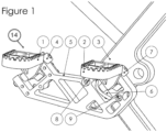
- Figure 1 shows a footrest arrangement 14 with one added foldable footrest device 1 in addition to the footrest device 2, where footrest device 2 is closest to the front wheel of the motorcycle. Both foldable footrest devices 1 and 2 are shown in the regular riding position.
- the original foldable footrest device 2 has usually spring return to riding position.
- the additional footrest device 1 is fastened to the motorcycle frame 3 via a bolt 4 and an additional footrest device bracket 5.
- the bolt 4 defines the pivot axis for the footrest device 1.
- the additional footrest device bracket 5 is connected to the original footrest device bracket 6 via a bolt 7. This bolt 7 and the top of the original footrest device bracket 6 are transferring the load and torque from the additional footrest device bracket 5 to the motorcycle frame 3.
- the bolt 7 also defines the pivot axis for footrest device 2.
- two bolts 8 and 9 are added. Bolts 8 and 9 are pretensioned against the motorcycle frame structure.
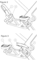
- Figure 2 shows the additional footrest device 1 in a folded away position, rotated around the pivot axis defined by the bolt 4.
- the additional footrest device 1 may also have spring return, as this is the common solution for regular footrest devices. But it may also stay fixed in the folded position when put there by the rider, either by spring induced friction, or by a spring-loaded detent mechanism. This functionality is important on motorcycles equipped with kick-start pedal. Some riders may also prefer the traditional arrangement with only one footrest device on each side of the motorcycle, when using trials riding techniques in extreme terrain.
- Figure 3 shows that the functionality with foldable footrest devices is maintained for the original footrest device 2 pivoting around a pivot axis defined by the bolt 7 even with the additional footrest device bracket 5 installed.
- the additional footrest device 1 in figure 3 is shown in regular riding position.
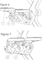
- Figure 4 shows prior art, the generic structure solution of all off-road motorcycles, with a footrest device bracket 6 with a slanted pivot axis 10 connected to the motorcycle frame 3.
- the hole in the motorcycle frame 11 is the hole for the swingarm axle that is connecting the swingarm to the motorcycle frame. This information is only given to describe the approximate generic placement of the footrest device, with respect to the motorcycle frame structure.
- Figure 5 shows prior art, the generic assembly of the footrest device arrangement used on all off-road motorcycles, with a footrest device 2 assembled to the footrest device bracket 6 with a footrest device axle 12 which defines a slanted pivot axis for the footrest device 2, where the footrest device bracket is either welded or bolted to the motorcycle frame structure 3.
- Figure 6 shows that the additional footrest device bracket 5 is made with a wider gap than the height of the additional footrest device 1 along the pivot axis defined by bolt 4, thus allowing a distance A available for adjusting the height of additional footrest device 1 with respect to the footrest device 2 by adding shim washers between the footrest device 1 and the footrest device bracket 5, according to each individual rider's preferences.
- Figure 7 shows a bracket for the sidestand support of the motorcycle 13, connected to the additional footrest device bracket 5.
Landscapes
- Engineering & Computer Science (AREA)
- Mechanical Engineering (AREA)
- Physics & Mathematics (AREA)
- General Physics & Mathematics (AREA)
- Automation & Control Theory (AREA)
- Chemical & Material Sciences (AREA)
- Combustion & Propulsion (AREA)
- General Engineering & Computer Science (AREA)
- Motorcycle And Bicycle Frame (AREA)
- Automatic Cycles, And Cycles In General (AREA)
Claims (8)
- Zweirädriges Motorrad, umfassend eine Fußstützanordnung (14), wobei die Fußstützanordnung mindestens zwei einzeln schwenkbare Fußstützvorrichtungen (1, 2) mit Fußstützflächen umfasst, die relativ zueinander in einer Vorwärts-Rückwärts-Richtung des Motorrads angeordnet sind und einen inneren Abstand zwischen ihnen aufweisen, so dass ein Motorradfahrer gleichzeitig mit einem Fuß auf den Fußstützflächen stehen kann, dadurch gekennzeichnet, dass jede der Fußstützvorrichtungen (1, 2) mit einer jeweiligen Fußstützvorrichtungshalterung (5, 6) über einen jeweiligen Bolzen (4, 7) verbunden ist, der eine jeweilige schräge Schwenkachse definiert, die es ermöglicht, die entsprechende Fußstützvorrichtung (1, 2) zu falten, und die so ausgerichtet ist, dass die entsprechende Fußstützvorrichtung (1, 2) gleichzeitig nach oben und nach hinten in Bezug auf das Motorrad gedrückt werden kann, wenn sie von etwas getroffen wird.
- Zweirädriges Motorrad nach Anspruch 1, wobei die Fußstützflächen in einer ausgeklappten Stellung der mindestens zwei Fußstützvorrichtungen (1, 2) im Wesentlichen in einer Ebene angeordnet sind.
- Zweirädriges Motorrad nach Anspruch 2, wobei die eine oder mehreren zusätzlichen Fußstützvorrichtungen (1) der mindestens zwei Fußstützvorrichtungen neben der Fußstützvorrichtung (2) der mindestens zwei Fußstützvorrichtungen (1, 2), die dem Vorderrad des Motorrads am nächstgelegen ist, so angeordnet sind, dass sie in einer weggeklappten Position bleiben, wenn sie vom Motorradfahrer in diese Position gebracht werden.
- Zweirädriges Motorrad nach einem der vorstehenden Ansprüche, wobei die Fußstützvorrichtungshalterung (5), mit der die eine oder mehreren zusätzlichen Fußstützvorrichtungen (1) der mindestens zwei Fußstützvorrichtungen (1, 2) neben der Fußstützvorrichtung (2) der mindestens zwei Fußstützvorrichtungen (1, 2), die dem Vorderrad des Motorrads am nächsten ist, verbunden sind, eine zusätzliche Fußstützvorrichtungshalterung (5) darstellt, die so angeordnet ist, dass sie an einem Motorrad nachgerüstet werden kann, das ursprünglich auf jeder Seite mit nur einer ursprünglichen faltbaren Fußstützvorrichtung (2) ausgestattet war, die für den Motorradfahrer bestimmt ist, indem eine ursprüngliche Fußstützvorrichtungshalterung (6) als der Hauptschnittstellenpunkt zwischen der zusätzlichen Fußstützvorrichtungshalterung (5) und der Motorradrahmenstruktur (3) des Motorrads verwendet wird.
- Zweirädriges Motorrad nach einem der Ansprüche 1 bis 3, wobei die Fußstützvorrichtungshalterungen (5, 6) in die Motorradrahmenstruktur (3) des Motorrads integriert sind.
- Zweirädriges Motorrad nach einem der Ansprüche 4 oder 5, wobei die eine oder mehreren zusätzlichen Fußstützvorrichtungen (1) in Bezug auf die Fußstützvorrichtung (2) der mindestens zwei Fußstützvorrichtungen (1, 2), die dem Vorderrad des Motorrads am nächsten ist, höhenverstellbar sind.
- Zweirädriges Motorrad nach Anspruch 4 oder Anspruch 6 in Abhängigkeit von Anspruch 4, wobei eine Halterung (13) für eine Motorrad-Seitenständerhalterung des Motorrads mit der zusätzlichen Fußstützhalterung (5) entweder auf der rechten oder der linken Seite des Motorrads verbunden oder in die zusätzliche Fußstützhalterung (5) integriert ist.
- Zweirädriges Motorrad nach einem der vorstehenden Ansprüche, wobei der Abstand zwischen den jeweiligen Mittelpunkten der Fußstützflächen zwischen 60 und 250 mm beträgt.
Applications Claiming Priority (2)
| Application Number | Priority Date | Filing Date | Title |
|---|---|---|---|
| NO20180190A NO344159B1 (en) | 2018-02-06 | 2018-02-06 | Footrest arrangement for motorcycle |
| PCT/NO2019/050017 WO2019156569A1 (en) | 2018-02-06 | 2019-01-24 | Footrest arrangement for a motorcycle |
Publications (4)
| Publication Number | Publication Date |
|---|---|
| EP3749569A1 EP3749569A1 (de) | 2020-12-16 |
| EP3749569A4 EP3749569A4 (de) | 2021-09-08 |
| EP3749569B1 true EP3749569B1 (de) | 2024-09-25 |
| EP3749569C0 EP3749569C0 (de) | 2024-09-25 |
Family
ID=67548988
Family Applications (1)
| Application Number | Title | Priority Date | Filing Date |
|---|---|---|---|
| EP19750894.8A Active EP3749569B1 (de) | 2018-02-06 | 2019-01-24 | Zweirädriges motorrad mit einer fussstützenanordnung |
Country Status (8)
| Country | Link |
|---|---|
| US (1) | US11400993B2 (de) |
| EP (1) | EP3749569B1 (de) |
| AU (2) | AU2019217211A1 (de) |
| CA (1) | CA3089944A1 (de) |
| ES (1) | ES2989320T3 (de) |
| NO (1) | NO344159B1 (de) |
| PL (1) | PL3749569T3 (de) |
| WO (1) | WO2019156569A1 (de) |
Families Citing this family (1)
| Publication number | Priority date | Publication date | Assignee | Title |
|---|---|---|---|---|
| US11242103B2 (en) * | 2020-05-06 | 2022-02-08 | Lindby Custom, Inc | Foot rest assembly for motorcycles |
Citations (1)
| Publication number | Priority date | Publication date | Assignee | Title |
|---|---|---|---|---|
| US6957821B2 (en) * | 2003-01-17 | 2005-10-25 | Mark Gorman | Safety device for motorcycle foot pegs |
Family Cites Families (15)
| Publication number | Priority date | Publication date | Assignee | Title |
|---|---|---|---|---|
| JPS60244682A (ja) | 1984-05-21 | 1985-12-04 | ヤマハ発動機株式会社 | 荒地走行用車輛 |
| JPH0788186B2 (ja) * | 1985-09-12 | 1995-09-27 | ヤマハ発動機株式会社 | フ−トレストの取付構造 |
| JP2780198B2 (ja) | 1989-10-25 | 1998-07-30 | スズキ株式会社 | オートバイのフートレストなどの取付け装置 |
| JP3594158B2 (ja) | 1996-08-30 | 2004-11-24 | 本田技研工業株式会社 | 自動二輪車の車体フレーム構造 |
| US7111375B2 (en) | 2003-04-10 | 2006-09-26 | Harley-Davidson Motor Company Group, Inc. | Footpeg for a motorcycle |
| US6893038B2 (en) * | 2003-07-16 | 2005-05-17 | Kuryakyn Holdings, Inc. | Motorcycle foot peg with folding heel rest |
| EP2445777B1 (de) * | 2009-06-26 | 2014-06-25 | Thomas M. Crain | Fussklammer für ein grätschsitzfahrzeug |
| WO2011035365A1 (en) * | 2009-09-24 | 2011-03-31 | Byron Bruggemann | Motor bike foot pegs |
| US8444165B2 (en) * | 2010-03-15 | 2013-05-21 | Jessica Renee Houser | Guard bar and tunable footpeg system for all-terrain vehicles |
| US8870207B2 (en) * | 2011-02-16 | 2014-10-28 | Kuryakyn Holdings, LLC | Motorcycle pivotable passenger peg assembly |
| US20130043668A1 (en) * | 2011-08-15 | 2013-02-21 | Allred & Associates Inc. | Motorcycle footrest peg reinforcement |
| JP6001000B2 (ja) | 2014-03-27 | 2016-10-05 | 本田技研工業株式会社 | 鞍乗型車両のステップ構造 |
| JP6078111B2 (ja) * | 2015-06-24 | 2017-02-08 | 本田技研工業株式会社 | 鞍乗り型車両 |
| US20180001951A1 (en) * | 2016-06-30 | 2018-01-04 | Ciro, LLC | Mounting arm for motorcycle floorboard and foot peg |
| WO2018060952A2 (en) * | 2016-09-30 | 2018-04-05 | Bombardier Recreational Products Inc. | Adjustable footrest for a vehicle |
-
2018
- 2018-02-06 NO NO20180190A patent/NO344159B1/en unknown
-
2019
- 2019-01-24 AU AU2019217211A patent/AU2019217211A1/en active Pending
- 2019-01-24 US US16/967,638 patent/US11400993B2/en active Active
- 2019-01-24 EP EP19750894.8A patent/EP3749569B1/de active Active
- 2019-01-24 ES ES19750894T patent/ES2989320T3/es active Active
- 2019-01-24 AU AU2019101825A patent/AU2019101825A4/en active Active
- 2019-01-24 CA CA3089944A patent/CA3089944A1/en active Pending
- 2019-01-24 WO PCT/NO2019/050017 patent/WO2019156569A1/en not_active Ceased
- 2019-01-24 PL PL19750894.8T patent/PL3749569T3/pl unknown
Patent Citations (1)
| Publication number | Priority date | Publication date | Assignee | Title |
|---|---|---|---|---|
| US6957821B2 (en) * | 2003-01-17 | 2005-10-25 | Mark Gorman | Safety device for motorcycle foot pegs |
Also Published As
| Publication number | Publication date |
|---|---|
| PL3749569T3 (pl) | 2025-01-27 |
| NO344159B1 (en) | 2019-09-23 |
| EP3749569A1 (de) | 2020-12-16 |
| NO20180190A1 (en) | 2019-08-07 |
| EP3749569A4 (de) | 2021-09-08 |
| US20210086856A1 (en) | 2021-03-25 |
| AU2019217211A1 (en) | 2020-08-13 |
| WO2019156569A1 (en) | 2019-08-15 |
| US11400993B2 (en) | 2022-08-02 |
| AU2019217211A2 (en) | 2022-03-17 |
| AU2019101825A4 (en) | 2022-03-31 |
| CA3089944A1 (en) | 2019-08-15 |
| ES2989320T3 (es) | 2024-11-26 |
| EP3749569C0 (de) | 2024-09-25 |
Similar Documents
| Publication | Publication Date | Title |
|---|---|---|
| US7637338B2 (en) | All-terrain vehicle | |
| US7802646B2 (en) | Snow vehicle | |
| US6719316B1 (en) | Motorcycle footrest | |
| US8562004B2 (en) | Children'S knee boards and methods of riding the same | |
| US20040035624A1 (en) | Components for a three-wheeled vehicle to permit leaning of the driver | |
| US8322735B2 (en) | Freestyle scooter | |
| US7025368B2 (en) | Protective cage for motorcycle engine | |
| JP2002524338A (ja) | スノータイプバイク | |
| US7270213B2 (en) | Wheeled vehicle with foot rest | |
| EP3749569B1 (de) | Zweirädriges motorrad mit einer fussstützenanordnung | |
| US9242697B2 (en) | Foot peg for straddle-type vehicle | |
| US11685463B2 (en) | Steering linkage for bicycles | |
| TW200305520A (en) | Bicycle straddled seat and rider support structure in bicycle | |
| KR102031905B1 (ko) | 오토바이용 리어셋 어셈블리 | |
| WO1999029562A1 (en) | Motorcycle | |
| US20240227978A9 (en) | Fork arch | |
| JPS629193Y2 (de) | ||
| WO2025027358A1 (en) | A stabilizing device for a two-wheeled vehicle |
Legal Events
| Date | Code | Title | Description |
|---|---|---|---|
| STAA | Information on the status of an ep patent application or granted ep patent |
Free format text: STATUS: THE INTERNATIONAL PUBLICATION HAS BEEN MADE |
|
| PUAI | Public reference made under article 153(3) epc to a published international application that has entered the european phase |
Free format text: ORIGINAL CODE: 0009012 |
|
| STAA | Information on the status of an ep patent application or granted ep patent |
Free format text: STATUS: REQUEST FOR EXAMINATION WAS MADE |
|
| 17P | Request for examination filed |
Effective date: 20200724 |
|
| AK | Designated contracting states |
Kind code of ref document: A1 Designated state(s): AL AT BE BG CH CY CZ DE DK EE ES FI FR GB GR HR HU IE IS IT LI LT LU LV MC MK MT NL NO PL PT RO RS SE SI SK SM TR |
|
| AX | Request for extension of the european patent |
Extension state: BA ME |
|
| DAV | Request for validation of the european patent (deleted) | ||
| DAX | Request for extension of the european patent (deleted) | ||
| REG | Reference to a national code |
Ref country code: DE Ref legal event code: R079 Free format text: PREVIOUS MAIN CLASS: B62J0025000000 Ipc: B62J0025060000 Ref country code: DE Ref legal event code: R079 Ref document number: 602019059442 Country of ref document: DE Free format text: PREVIOUS MAIN CLASS: B62J0025000000 Ipc: B62J0025060000 |
|
| A4 | Supplementary search report drawn up and despatched |
Effective date: 20210810 |
|
| RIC1 | Information provided on ipc code assigned before grant |
Ipc: B62H 1/02 20060101ALI20210804BHEP Ipc: B62J 25/06 20200101AFI20210804BHEP |
|
| STAA | Information on the status of an ep patent application or granted ep patent |
Free format text: STATUS: EXAMINATION IS IN PROGRESS |
|
| 17Q | First examination report despatched |
Effective date: 20230203 |
|
| GRAP | Despatch of communication of intention to grant a patent |
Free format text: ORIGINAL CODE: EPIDOSNIGR1 |
|
| STAA | Information on the status of an ep patent application or granted ep patent |
Free format text: STATUS: GRANT OF PATENT IS INTENDED |
|
| INTG | Intention to grant announced |
Effective date: 20240424 |
|
| GRAS | Grant fee paid |
Free format text: ORIGINAL CODE: EPIDOSNIGR3 |
|
| GRAA | (expected) grant |
Free format text: ORIGINAL CODE: 0009210 |
|
| STAA | Information on the status of an ep patent application or granted ep patent |
Free format text: STATUS: THE PATENT HAS BEEN GRANTED |
|
| AK | Designated contracting states |
Kind code of ref document: B1 Designated state(s): AL AT BE BG CH CY CZ DE DK EE ES FI FR GB GR HR HU IE IS IT LI LT LU LV MC MK MT NL NO PL PT RO RS SE SI SK SM TR |
|
| REG | Reference to a national code |
Ref country code: GB Ref legal event code: FG4D |
|
| REG | Reference to a national code |
Ref country code: CH Ref legal event code: EP |
|
| REG | Reference to a national code |
Ref country code: DE Ref legal event code: R096 Ref document number: 602019059442 Country of ref document: DE |
|
| REG | Reference to a national code |
Ref country code: IE Ref legal event code: FG4D |
|
| U01 | Request for unitary effect filed |
Effective date: 20241015 |
|
| REG | Reference to a national code |
Ref country code: ES Ref legal event code: FG2A Ref document number: 2989320 Country of ref document: ES Kind code of ref document: T3 Effective date: 20241126 |
|
| U07 | Unitary effect registered |
Designated state(s): AT BE BG DE DK EE FI FR IT LT LU LV MT NL PT RO SE SI Effective date: 20241031 |
|
| PG25 | Lapsed in a contracting state [announced via postgrant information from national office to epo] |
Ref country code: NO Free format text: LAPSE BECAUSE OF FAILURE TO SUBMIT A TRANSLATION OF THE DESCRIPTION OR TO PAY THE FEE WITHIN THE PRESCRIBED TIME-LIMIT Effective date: 20241225 |
|
| PG25 | Lapsed in a contracting state [announced via postgrant information from national office to epo] |
Ref country code: GR Free format text: LAPSE BECAUSE OF FAILURE TO SUBMIT A TRANSLATION OF THE DESCRIPTION OR TO PAY THE FEE WITHIN THE PRESCRIBED TIME-LIMIT Effective date: 20241226 |
|
| PG25 | Lapsed in a contracting state [announced via postgrant information from national office to epo] |
Ref country code: RS Free format text: LAPSE BECAUSE OF FAILURE TO SUBMIT A TRANSLATION OF THE DESCRIPTION OR TO PAY THE FEE WITHIN THE PRESCRIBED TIME-LIMIT Effective date: 20241225 |
|
| PG25 | Lapsed in a contracting state [announced via postgrant information from national office to epo] |
Ref country code: RS Free format text: LAPSE BECAUSE OF FAILURE TO SUBMIT A TRANSLATION OF THE DESCRIPTION OR TO PAY THE FEE WITHIN THE PRESCRIBED TIME-LIMIT Effective date: 20241225 Ref country code: NO Free format text: LAPSE BECAUSE OF FAILURE TO SUBMIT A TRANSLATION OF THE DESCRIPTION OR TO PAY THE FEE WITHIN THE PRESCRIBED TIME-LIMIT Effective date: 20241225 Ref country code: GR Free format text: LAPSE BECAUSE OF FAILURE TO SUBMIT A TRANSLATION OF THE DESCRIPTION OR TO PAY THE FEE WITHIN THE PRESCRIBED TIME-LIMIT Effective date: 20241226 |
|
| U20 | Renewal fee for the european patent with unitary effect paid |
Year of fee payment: 7 Effective date: 20250121 |
|
| PG25 | Lapsed in a contracting state [announced via postgrant information from national office to epo] |
Ref country code: IS Free format text: LAPSE BECAUSE OF FAILURE TO SUBMIT A TRANSLATION OF THE DESCRIPTION OR TO PAY THE FEE WITHIN THE PRESCRIBED TIME-LIMIT Effective date: 20250125 |
|
| PG25 | Lapsed in a contracting state [announced via postgrant information from national office to epo] |
Ref country code: SM Free format text: LAPSE BECAUSE OF FAILURE TO SUBMIT A TRANSLATION OF THE DESCRIPTION OR TO PAY THE FEE WITHIN THE PRESCRIBED TIME-LIMIT Effective date: 20240925 |
|
| PGFP | Annual fee paid to national office [announced via postgrant information from national office to epo] |
Ref country code: ES Payment date: 20250205 Year of fee payment: 7 |
|
| PG25 | Lapsed in a contracting state [announced via postgrant information from national office to epo] |
Ref country code: CZ Free format text: LAPSE BECAUSE OF FAILURE TO SUBMIT A TRANSLATION OF THE DESCRIPTION OR TO PAY THE FEE WITHIN THE PRESCRIBED TIME-LIMIT Effective date: 20240925 |
|
| PGFP | Annual fee paid to national office [announced via postgrant information from national office to epo] |
Ref country code: PL Payment date: 20250121 Year of fee payment: 7 |
|
| PG25 | Lapsed in a contracting state [announced via postgrant information from national office to epo] |
Ref country code: SK Free format text: LAPSE BECAUSE OF FAILURE TO SUBMIT A TRANSLATION OF THE DESCRIPTION OR TO PAY THE FEE WITHIN THE PRESCRIBED TIME-LIMIT Effective date: 20240925 |
|
| PGFP | Annual fee paid to national office [announced via postgrant information from national office to epo] |
Ref country code: GB Payment date: 20250124 Year of fee payment: 7 |
|
| PLBE | No opposition filed within time limit |
Free format text: ORIGINAL CODE: 0009261 |
|
| STAA | Information on the status of an ep patent application or granted ep patent |
Free format text: STATUS: NO OPPOSITION FILED WITHIN TIME LIMIT |
|
| REG | Reference to a national code |
Ref country code: CH Ref legal event code: PL |
|
| 26N | No opposition filed |
Effective date: 20250626 |
|
| PG25 | Lapsed in a contracting state [announced via postgrant information from national office to epo] |
Ref country code: MC Free format text: LAPSE BECAUSE OF FAILURE TO SUBMIT A TRANSLATION OF THE DESCRIPTION OR TO PAY THE FEE WITHIN THE PRESCRIBED TIME-LIMIT Effective date: 20240925 |
|
| PG25 | Lapsed in a contracting state [announced via postgrant information from national office to epo] |
Ref country code: CH Free format text: LAPSE BECAUSE OF NON-PAYMENT OF DUE FEES Effective date: 20250131 |
|
| PG25 | Lapsed in a contracting state [announced via postgrant information from national office to epo] |
Ref country code: HR Free format text: LAPSE BECAUSE OF FAILURE TO SUBMIT A TRANSLATION OF THE DESCRIPTION OR TO PAY THE FEE WITHIN THE PRESCRIBED TIME-LIMIT Effective date: 20240925 |
|
| PG25 | Lapsed in a contracting state [announced via postgrant information from national office to epo] |
Ref country code: IE Free format text: LAPSE BECAUSE OF NON-PAYMENT OF DUE FEES Effective date: 20250124 |
|
| U20 | Renewal fee for the european patent with unitary effect paid |
Year of fee payment: 8 Effective date: 20260120 |