EP3749537B1 - Module de commande de pulseur et installation de chauffage et/ou ventilation et/ou climatisation correspondante - Google Patents
Module de commande de pulseur et installation de chauffage et/ou ventilation et/ou climatisation correspondante Download PDFInfo
- Publication number
- EP3749537B1 EP3749537B1 EP19710038.1A EP19710038A EP3749537B1 EP 3749537 B1 EP3749537 B1 EP 3749537B1 EP 19710038 A EP19710038 A EP 19710038A EP 3749537 B1 EP3749537 B1 EP 3749537B1
- Authority
- EP
- European Patent Office
- Prior art keywords
- control module
- heat dissipation
- heat sink
- blower
- heat
- Prior art date
- Legal status (The legal status is an assumption and is not a legal conclusion. Google has not performed a legal analysis and makes no representation as to the accuracy of the status listed.)
- Active
Links
- 238000010438 heat treatment Methods 0.000 title claims description 18
- 238000009423 ventilation Methods 0.000 title claims description 14
- 238000004378 air conditioning Methods 0.000 title claims description 13
- 230000017525 heat dissipation Effects 0.000 claims description 70
- 238000009434 installation Methods 0.000 claims description 29
- 238000003780 insertion Methods 0.000 claims description 13
- 230000037431 insertion Effects 0.000 claims description 13
- 238000001816 cooling Methods 0.000 claims description 6
- 230000005669 field effect Effects 0.000 description 4
- 239000004065 semiconductor Substances 0.000 description 4
- 230000005465 channeling Effects 0.000 description 2
- 230000000295 complement effect Effects 0.000 description 2
- 239000004020 conductor Substances 0.000 description 2
- 229910044991 metal oxide Inorganic materials 0.000 description 2
- 150000004706 metal oxides Chemical class 0.000 description 2
- 238000004026 adhesive bonding Methods 0.000 description 1
- 238000004891 communication Methods 0.000 description 1
- 238000010586 diagram Methods 0.000 description 1
- 230000004907 flux Effects 0.000 description 1
- 238000012423 maintenance Methods 0.000 description 1
- 239000000463 material Substances 0.000 description 1
- 239000002184 metal Substances 0.000 description 1
- 230000007935 neutral effect Effects 0.000 description 1
- 230000000717 retained effect Effects 0.000 description 1
- 239000002470 thermal conductor Substances 0.000 description 1
- 238000003466 welding Methods 0.000 description 1
Images

Classifications
-
- B—PERFORMING OPERATIONS; TRANSPORTING
- B60—VEHICLES IN GENERAL
- B60H—ARRANGEMENTS OF HEATING, COOLING, VENTILATING OR OTHER AIR-TREATING DEVICES SPECIALLY ADAPTED FOR PASSENGER OR GOODS SPACES OF VEHICLES
- B60H1/00—Heating, cooling or ventilating [HVAC] devices
- B60H1/00507—Details, e.g. mounting arrangements, desaeration devices
- B60H1/00557—Details of ducts or cables
- B60H1/00564—Details of ducts or cables of air ducts
-
- B—PERFORMING OPERATIONS; TRANSPORTING
- B60—VEHICLES IN GENERAL
- B60H—ARRANGEMENTS OF HEATING, COOLING, VENTILATING OR OTHER AIR-TREATING DEVICES SPECIALLY ADAPTED FOR PASSENGER OR GOODS SPACES OF VEHICLES
- B60H1/00—Heating, cooling or ventilating [HVAC] devices
- B60H1/00007—Combined heating, ventilating, or cooling devices
- B60H1/00021—Air flow details of HVAC devices
-
- B—PERFORMING OPERATIONS; TRANSPORTING
- B60—VEHICLES IN GENERAL
- B60H—ARRANGEMENTS OF HEATING, COOLING, VENTILATING OR OTHER AIR-TREATING DEVICES SPECIALLY ADAPTED FOR PASSENGER OR GOODS SPACES OF VEHICLES
- B60H1/00—Heating, cooling or ventilating [HVAC] devices
- B60H1/00457—Ventilation unit, e.g. combined with a radiator
- B60H1/00471—The ventilator being of the radial type, i.e. with radial expulsion of the air
-
- F—MECHANICAL ENGINEERING; LIGHTING; HEATING; WEAPONS; BLASTING
- F04—POSITIVE - DISPLACEMENT MACHINES FOR LIQUIDS; PUMPS FOR LIQUIDS OR ELASTIC FLUIDS
- F04D—NON-POSITIVE-DISPLACEMENT PUMPS
- F04D25/00—Pumping installations or systems
- F04D25/02—Units comprising pumps and their driving means
- F04D25/08—Units comprising pumps and their driving means the working fluid being air, e.g. for ventilation
-
- F—MECHANICAL ENGINEERING; LIGHTING; HEATING; WEAPONS; BLASTING
- F04—POSITIVE - DISPLACEMENT MACHINES FOR LIQUIDS; PUMPS FOR LIQUIDS OR ELASTIC FLUIDS
- F04D—NON-POSITIVE-DISPLACEMENT PUMPS
- F04D27/00—Control, e.g. regulation, of pumps, pumping installations or pumping systems specially adapted for elastic fluids
- F04D27/004—Control, e.g. regulation, of pumps, pumping installations or pumping systems specially adapted for elastic fluids by varying driving speed
-
- F—MECHANICAL ENGINEERING; LIGHTING; HEATING; WEAPONS; BLASTING
- F04—POSITIVE - DISPLACEMENT MACHINES FOR LIQUIDS; PUMPS FOR LIQUIDS OR ELASTIC FLUIDS
- F04D—NON-POSITIVE-DISPLACEMENT PUMPS
- F04D29/00—Details, component parts, or accessories
- F04D29/26—Rotors specially for elastic fluids
- F04D29/28—Rotors specially for elastic fluids for centrifugal or helico-centrifugal pumps for radial-flow or helico-centrifugal pumps
- F04D29/281—Rotors specially for elastic fluids for centrifugal or helico-centrifugal pumps for radial-flow or helico-centrifugal pumps for fans or blowers
- F04D29/282—Rotors specially for elastic fluids for centrifugal or helico-centrifugal pumps for radial-flow or helico-centrifugal pumps for fans or blowers the leading edge of each vane being substantially parallel to the rotation axis
-
- F—MECHANICAL ENGINEERING; LIGHTING; HEATING; WEAPONS; BLASTING
- F04—POSITIVE - DISPLACEMENT MACHINES FOR LIQUIDS; PUMPS FOR LIQUIDS OR ELASTIC FLUIDS
- F04D—NON-POSITIVE-DISPLACEMENT PUMPS
- F04D29/00—Details, component parts, or accessories
- F04D29/58—Cooling; Heating; Diminishing heat transfer
- F04D29/5813—Cooling the control unit
-
- F—MECHANICAL ENGINEERING; LIGHTING; HEATING; WEAPONS; BLASTING
- F04—POSITIVE - DISPLACEMENT MACHINES FOR LIQUIDS; PUMPS FOR LIQUIDS OR ELASTIC FLUIDS
- F04D—NON-POSITIVE-DISPLACEMENT PUMPS
- F04D29/00—Details, component parts, or accessories
- F04D29/58—Cooling; Heating; Diminishing heat transfer
- F04D29/582—Cooling; Heating; Diminishing heat transfer specially adapted for elastic fluid pumps
- F04D29/5826—Cooling at least part of the working fluid in a heat exchanger
-
- B—PERFORMING OPERATIONS; TRANSPORTING
- B60—VEHICLES IN GENERAL
- B60H—ARRANGEMENTS OF HEATING, COOLING, VENTILATING OR OTHER AIR-TREATING DEVICES SPECIALLY ADAPTED FOR PASSENGER OR GOODS SPACES OF VEHICLES
- B60H1/00—Heating, cooling or ventilating [HVAC] devices
- B60H1/00271—HVAC devices specially adapted for particular vehicle parts or components and being connected to the vehicle HVAC unit
- B60H2001/003—Component temperature regulation using an air flow
-
- B—PERFORMING OPERATIONS; TRANSPORTING
- B60—VEHICLES IN GENERAL
- B60H—ARRANGEMENTS OF HEATING, COOLING, VENTILATING OR OTHER AIR-TREATING DEVICES SPECIALLY ADAPTED FOR PASSENGER OR GOODS SPACES OF VEHICLES
- B60H1/00—Heating, cooling or ventilating [HVAC] devices
- B60H1/00507—Details, e.g. mounting arrangements, desaeration devices
- B60H2001/00614—Cooling of electronic units in air stream
-
- F—MECHANICAL ENGINEERING; LIGHTING; HEATING; WEAPONS; BLASTING
- F05—INDEXING SCHEMES RELATING TO ENGINES OR PUMPS IN VARIOUS SUBCLASSES OF CLASSES F01-F04
- F05D—INDEXING SCHEME FOR ASPECTS RELATING TO NON-POSITIVE-DISPLACEMENT MACHINES OR ENGINES, GAS-TURBINES OR JET-PROPULSION PLANTS
- F05D2250/00—Geometry
- F05D2250/50—Inlet or outlet
- F05D2250/52—Outlet
Definitions
- the invention relates to the field of ventilation, heating and / or air conditioning installations, in particular for a motor vehicle.
- the invention relates in particular to a module for controlling a blower for such an installation.
- Heating and / or ventilation and / or air conditioning systems for a motor vehicle also known under the English name HVAC (for Heating, Ventilation and Air-Conditioning) make it possible to distribute air in a vehicle interior and generally include a duct air in which various means of heat treatment of the air are arranged.
- the means for heat treatment of the air are in particular heat exchangers, for heating and / or cooling, for example an air heating radiator and an evaporator intended to cool the air.
- the air flow circulating in the heating and / or ventilation and / or air conditioning installation is generated by a motor-fan unit, also called a blower or air blower, which is mounted at the level of a volute of the installation ensuring the channeling of the air flow.
- the air flow is directed, via the blower, to one or more outlets of the installation opening into the passenger compartment, after having been heat treated.
- the blower comprises in particular a fan wheel or turbine housed in the volute to generate an air flow therein, and an electric drive motor capable of rotating the fan wheel.
- the blower and more precisely the drive motor, is controlled by a control module.
- the control module makes it possible in particular to vary the speed of the engine as required and for this purpose comprises components, more particularly electrical and electronic components, including power electronic components, in particular active power electronic components. Mention may be made, for example, of semiconductor components such as diodes, transistors, in particular insulated gate field effect transistors known by the English acronym MOSFET for “Metal Oxide Semiconductor Field Effect Transistor”.
- MOSFET Metal Oxide Semiconductor Field Effect Transistor
- One problem is the cooling of the control module.
- active power electronic components such as MOSFETs can reach a temperature of the order of 175 ° C. If the temperature of the control module exceeds a predefined maximum temperature, this risks damaging certain elements of the control module such as the power electronic components or even a printed circuit board electrically connected to them.
- the heat sink is generally screwed onto the printed circuit board on which the electronic power component (s) of the control module is or are mounted.
- the heat sink has fins which are arranged to be exposed to the air flow generated in the volute.
- the heat sink is generally placed at the outlet of the volute.
- a heat dissipation interface also called heat dissipation sole can be arranged on the heat sink on the side opposite the fins, between the heat sink and the printed circuit board.
- the document FROM 10 2010 046672 discloses a known type of control module for a blower for a heating and / or ventilation and / or air conditioning installation, in particular for a motor vehicle, the blower being configured to generate an air flow and the control module being configured as the blower and comprising a heat sink, a heat dissipation sole, and at least one active power electronic component mounted on the heat dissipation sole.
- the object of the invention is to ensure efficient cooling of the components of the control module while improving and making the assembly between the control module and the heat sink more reliable.
- control module for a blower for a heating and / or ventilation and / or air conditioning installation, in particular for a motor vehicle, the blower being configured to generate an air flow and the blower module.
- control being configured to drive the blower and comprises a heat sink, a heat dissipation sole and at least one active power electronic component mounted on the heat dissipation sole.
- the heat sink comprises a housing for receiving at least part of the heat dissipation sole, and the heat dissipation sole is mounted by force fitting in said housing.
- the heat sink presses on the heat dissipation sole forcibly fitted into the housing provided for this purpose at the level of the heat sink.
- the heat sink is therefore shaped to receive and cooperate with the heat dissipation sole in order to assemble and maintain the active component in thermal contact on the heat sink.
- the invention also relates to a heating and / or ventilation and / or air conditioning installation comprising a blower configured to generate an air flow, and at least one control module as defined above.
- certain elements can be indexed, such as for example first or second element. In this case, it is a simple indexing to differentiate and name similar elements but not identical. This indexing does not imply a priority of one element over another and such names can easily be interchanged without departing from the scope of the present description. This indexation does not imply an order in time either.
- FIG. 1 schematically shows part of a heating and / or ventilation and / or air conditioning installation 1, hereinafter referred to as installation 1, in particular for a motor vehicle.
- the installation 1 defines at least one channel 2 inside which at least one air flow is able to circulate.
- Such an installation 1 comprises a motor-fan unit also called a blower or air blower 3 (see Figures 1 and 2 ), capable of generating an air flow.
- a motor-fan unit also called a blower or air blower 3 (see Figures 1 and 2 ), capable of generating an air flow.
- the installation 1 comprises a volute 5, in which the blower 3 is intended to be mounted, and which ensures the channeling of the air flow generated by the blower 3.
- Volute 5 may have a substantially spiral shape. The volute 5 then presents an outline starting with a zone called “volute nose” and which progresses to an exit 51.
- the blower 3 makes it possible to direct the air flow towards a duct 7 of the installation 1 which distributes the air flow to outlet openings which open into the passenger compartment of the vehicle.
- the outlet 51 of volute 5 is connected to the duct 7.
- volute 5 and the duct 7 delimit the circulation channel 2 for the air flow generated by the blower 3.
- the air flow can undergo at least one heat treatment, for example it can be heated or cooled.
- the installation 1 further comprises one or more heat exchangers 9 arranged in the duct 7 and intended to be passed through by the air flow. These heat exchangers 9 known to those skilled in the art of heating and / or ventilation installations and / or air conditioning are not described in more detail below.
- the blower 3 comprises a motor 31 and a wheel 33 also called a fan wheel or a blower wheel, intended to be driven by the motor 31, so as to ensure the setting in motion of the air flow.
- the motor 31 is configured to drive the fan wheel 33 in rotation about an axis of rotation A.
- the fan wheel 33 is housed inside the volute 5. On one of its sides, the volute 5 has an opening closed by a cover 11 forming a support for the motor 31 to drive the fan wheel 33.
- the motor 31 and the fan wheel 33 are coaxial.
- the fan wheel 33 has a generally substantially cylindrical shape, with an open face.
- the open face is on the side opposite to the cover 11 forming an engine support.
- This open face is, in the mounted state of the blower 3 in the installation 1, in aeraulic communication with one or more air inlets 11 (see FIG. 1), for example outside air coming from outside the unit. passenger compartment and / or recirculated air from the passenger compartment, from installation 1.
- the fan wheel 33 is configured to suck through this open face an air flow as shown schematically by the arrow F1 on the figure 2 , then to evacuate this air flow from the side, that is to say here radially with respect to the axis of rotation A, as shown diagrammatically by the arrows F2, when it is driven in rotation.
- the air sucked in and circulated by the fan wheel 33 is extracted from the volute 5 through the outlet 51.
- the fan wheel 33 has a part 331 forming a bottom, for example substantially bowl-shaped, which is arranged opposite the open face of the fan wheel 33.
- the fan wheel 33 further comprises a hub 333, for example substantially in the center of the bowl-shaped portion 331, to receive a free end of a drive shaft of the motor 31.
- the fan wheel 33 may include a plurality of blades 335 or vanes. The blades 335 in this example extend axially from the periphery of the bowl-shaped portion 331.
- Such a blower 3 is controlled by a control module 15 shown very schematically on the figure 2 . More precisely, the control module 15 makes it possible to control the motor 31, for example the speed of rotation of the motor 31 (not visible on the figure 2 ).
- This control module 15 is arranged in the installation 1, for example at the level of the outlet 51 of the volute 5, as illustrated in the figure. figure 2 .
- a cavity 14 may be provided on a wall of the outlet 51 of volute 5, to receive the control module 15.
- This location is by way of illustration and is not limiting.
- the control module 15 can be arranged elsewhere in the installation 1, for example on a wall of the duct 7 (also referring to FIG. 1).
- the location of the control module 15 can be chosen to limit the length of conductor cables between the control module 15 and the blower 3.
- the control module 15 generally comprises a printed circuit board (not shown in the figures).
- the printed circuit board has a circuit for powering the blower.
- the printed circuit board is in the form of a plate.
- the control module 15 comprises one or more electronic components, including at least one electronic power component electrically connected to the electrical supply circuit.
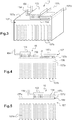
- the control module 15 comprises at least one active electronic power component 153, hereinafter referred to as “active component”, shown schematically on the diagrams. figures 3 to 5 .
- a component active 153 is an electronic component that increases the strength of a signal, can change state and conduct or block energy.
- a controllable component Mention may be made in the majority of semiconductor components, such as diodes, transistors, in particular insulated gate field effect transistors known by the English acronym MOSFET for “Metal Oxide Semiconductor Field Effect Transistor”.
- the active component 153 comprises a chip which is encapsulated in a plastic case.
- the active component 153 can be connected by at least one electrical connection member, such as electrical connection tabs or pins 154 ( figure 3 ), to the printed circuit board, in particular to the circuit.
- the printed circuit board is more limited in terms of temperature than the active component 153.
- the printed circuit board can reach a maximum temperature of the order of 150 ° C while the active component 153 can reach a maximum temperature above 150 ° C, in particular of the order of 175 ° C. vs.
- control module 15 further comprises a heat dissipation sole 158.
- a sole 158 is for example metallic. It may have the general shape of a plate.
- the active component 153 is mounted on the heat dissipation sole 158.
- the control module 15 further includes at least one heat sink 157 or heat sink heat sink (see figures 3 to 5 ).
- the heat sink 157 is configured to dissipate at least part of the heat generated in particular by the electronic power component (s) of the control module 15, such as the active component 153.
- the heat sink 157 is made of a thermally conductive material. It is for example a metal part.
- the heat sink 157 is connected to ground.
- the heat sink 157 comprises a base 157a, which can also be referred to as a base.
- the heat sink 157 for example also includes cooling fins 157b extending from the base 157a.
- the fins 157b are intended to be arranged in the air flow generated by the blower 3 (not visible on the figures 3 to 5 ), in the mounted state of the control module 15 in the installation 1 and in operation of the blower 3.
- the control module 15 is intended to be arranged in the installation so that the fins 157b of the heat sink 157 extend at least partly into the circulation channel 2 (not visible on the figures 3 to 5 ).
- the control module 15 and in particular the heat sink 157 can be mounted at a wall of the duct 7 or of the outlet 51 of the volute 5 (also referring to FIGS. 1 and 2 ).
- the heat sink 157 also has a wall 157c arranged facing the base 157a, on the side opposite the fins 157b.
- a flexible wall 157c (the flexibility of the wall may be due to its thickness and / or to the material used).
- the term “flexible” is understood to mean the fact that the wall 157c is capable of deforming under the action of an external force tending to move it away from the base 157a. In the free or neutral state, without exerted pressure, the flexible wall 157c can extend parallel or almost parallel to the base 157a.
- it may be a plane or substantially plane wall 157c. Finally, it is connected to the base 157a by one or more connecting parts 157d.
- the heat sink 157 has a space or a housing 156.
- This housing 156 is delimited between the base 157a of the heat sink 157 and the flexible wall 157c.
- a connection part 157d connects the flexible wall 157c to the base 157a, thus closing the housing 156 at one end.
- other connection parts 157d can be provided, so that the housing 156 is also closed on the side (s).
- the heat sink 157 is arranged in thermal contact with the active component 153.
- thermal contact is understood to mean the fact that two elements are arranged in direct contact. or assembled indirectly with the interposition of one or more thermal conductors, so as to allow in either case the conduction of the heat generated between these elements.
- the heat dissipation sole 158 on which the active component 153 is mounted is intended to be fixed to the heat sink 157. In this way, the active component 153 is arranged in thermal contact with the heat sink 157. through the heat dissipation sole 158, which allows the conduction of the heat generated by the active component 153 to the heat sink 157.
- the heat dissipation sole 158 is separate from the heat sink 157. It is therefore another part.
- the housing 156 is configured to receive at least part of this heat dissipation sole 158.
- the assembly is done by press-fitting. force of the heat dissipation sole 158 in the housing 156. This is also referred to as force tightening or “press-fit” in English.
- the heat dissipation sole 158 is configured to be inserted into the housing 156, for example according to a translational movement.
- the translational movement takes place in a direction of insertion D ( figure 4 ).
- the direction of insertion D can be parallel to the general plane defined by the base 157a of the heat sink 157.
- the insertion direction D is horizontal with reference to the arrangement of the elements in this figure. This representation is not limiting, the insertion direction D can be adapted according to the assembly configurations of the control module 15.
- the heat sink 157 may include a guide element for the heat dissipation sole 158 when it is inserted into the housing 156. This guiding function may be provided by the base 157a and / or the flexible wall 157c.
- the flexible wall 157c Upon insertion of the heat dissipating sole 158 into the housing 156, the flexible wall 157c is configured to move away from the base 157a. The flexible wall 157c therefore deforms outwardly of the housing 156. This increases the passage section for the heat dissipation sole 158 during its insertion into the housing 156.
- One or more end-of-travel stops of the heat dissipation sole 158 can be provided in the housing 156. These stops can be formed on or by the connection part or parts 157d. As a variant or in addition, the stops can be formed on or by the free end of the flexible wall 157c.
- the housing 156 is such that the heat sink 157 at least partially surrounds the heat dissipation sole 158 when it is mounted in the housing 156.
- the heat sink 157 comes both above and below the heat dissipation sole 158 with reference to the particular arrangement of the elements in these figures.
- the heat dissipation sole 158 when it is received in the housing 156, the heat dissipation sole 158 has at least two opposite faces which are arranged in contact with the heat sink 157.
- the heat dissipation sole 158 in the state mounted in the housing 156, has a first face arranged in contact with the base 157a while an opposite second face is arranged in contact with the flexible wall 157c.
- the heat dissipation sole 158 is in surface contact with both the flexible wall 157c and the base 157a of the heat sink 157. This ensures heat dissipation at least by these two sides of the heat dissipation sole 158.
- the heat dissipation sole 158 engages, or grips, in the housing 156 by formally cooperating with the heat sink 157.
- the heat sink 157 conforms to the shape of the heat dissipation sole 158 when it is formed. is inserted into the housing 156.
- the base 157a, the flexible wall 157c and the connection part or parts 157d define a housing 156 of a shape complementary to the shape of the heat dissipation sole 158.
- the heat sink 157 when the heat dissipating sole 158 is received in the housing 156, the heat sink 157 is able to exert an elastic pressure on this sole 158.
- the heat sink 157 comprises for this purpose at least one elastic retaining means of the heat dissipation sole 158 in the housing 156. It may be a clipping means.
- the flexible wall 157c which exerts such an elastic pressure and therefore forms the elastic retaining means.
- the flexible wall 157c firmly presses on the heat dissipation sole 158.
- the heat dissipation sole 158 is thus retained in the housing 156.
- the pressure is exerted on the heat dissipation sole 158 in a direction normal to the general plane defined by the heat dissipation sole 158.
- the heat dissipation sole 158 has a free surface, which is devoid of the active component 153, forming a bearing surface against which the flexible wall 157c is positioned and supported for example.
- the flexible wall 157c has at least one surface extending parallel to the heat dissipation sole 158, in particular to this free bearing surface, in the mounted state of the heat dissipation sole 158 in the housing 156.
- the flexible wall 157c extends over all or almost the entire free bearing surface of the heat dissipation sole 158.
- the heat sink 157 comprises at least one fixing element or member at the level of the housing 156, configured to cooperate with the sole of heat dissipation 158, so as to also participate in maintaining this sole 158 in the housing 15 (for example, complementary shapes can be arranged capable of cooperating with each other, the deformation of which would only be possible in the direction of mounting of the sole in the housing)
- the printed circuit board (not shown) is not arranged in the housing 156 formed by the heat sink 157. It is therefore remote from this housing 156. With this configuration, the heat dissipation generated by the active component is improved. 153 through the heat sink 157 intended to be cooled by the air flow.
- the heat dissipation sole 158 carrying a power electronic component which generates heat, such as the active component 153, is force-fitted into the housing 156 defined by the heat sink 157, to form the control module 15.
- C ' is a simple assembly, not requiring welding or gluing for example, which allows the positioning and maintenance of the active component 153 in thermal contact with the heat sink 157.
- This heat sink 157 is also intended to be cooled by the flow of air generated by blower 3 when control module 15 is mounted on installation 1.
- the flexible wall 157c forms a means for retaining the heat dissipation sole 158 in the housing 156.
- the cooperating surfaces with each other are the surfaces of the heat sink 157 and the heat dissipation sole 158, which are advantageously both metallic, so that there is no damage to the active component 153, more particularly of the plastic case in which the chip of the active component 153 is encapsulated.
Applications Claiming Priority (2)
| Application Number | Priority Date | Filing Date | Title |
|---|---|---|---|
| FR1851092A FR3077771B1 (fr) | 2018-02-09 | 2018-02-09 | Module de commande de pulseur et installation de chauffage et/ou ventilation et/ou climatisation correspondante |
| PCT/FR2019/050268 WO2019155164A1 (fr) | 2018-02-09 | 2019-02-07 | Module de commande de pulseur et installation de chauffage et/ou ventilation et/ou climatisation correspondante |
Publications (2)
| Publication Number | Publication Date |
|---|---|
| EP3749537A1 EP3749537A1 (fr) | 2020-12-16 |
| EP3749537B1 true EP3749537B1 (fr) | 2021-12-29 |
Family
ID=62455648
Family Applications (1)
| Application Number | Title | Priority Date | Filing Date |
|---|---|---|---|
| EP19710038.1A Active EP3749537B1 (fr) | 2018-02-09 | 2019-02-07 | Module de commande de pulseur et installation de chauffage et/ou ventilation et/ou climatisation correspondante |
Country Status (5)
| Country | Link |
|---|---|
| US (1) | US11535080B2 (zh) |
| EP (1) | EP3749537B1 (zh) |
| CN (1) | CN111836734B (zh) |
| FR (1) | FR3077771B1 (zh) |
| WO (1) | WO2019155164A1 (zh) |
Families Citing this family (3)
| Publication number | Priority date | Publication date | Assignee | Title |
|---|---|---|---|---|
| FR3087618B1 (fr) * | 2018-10-23 | 2020-10-02 | Valeo Systemes Thermiques | Dispositif de dissipation thermique, notamment pour dispositif de generation d’un flux d’air |
| EP3819139A1 (en) * | 2019-11-08 | 2021-05-12 | Volvo Car Corporation | A module for accomodating and cooling electronic circuitry in a vehicle |
| US20240025223A1 (en) * | 2022-07-22 | 2024-01-25 | Hanon Systems | Quad zone booster intake lpm cooling assembly |
Family Cites Families (9)
| Publication number | Priority date | Publication date | Assignee | Title |
|---|---|---|---|---|
| FR2742816B1 (fr) * | 1995-12-22 | 1998-01-30 | Valeo Climatisation | Dispositif de fixation d'un module de commande de ventilateur sur un conduit d'air |
| FR2766301B1 (fr) * | 1997-07-17 | 1999-09-10 | Valeo Climatisation | Moteur electrique, notamment pour vehicule automobile, a radiateur de refroidissement perfectionne |
| FR2868018A1 (fr) * | 2004-03-29 | 2005-09-30 | Valeo Climatisation Sa | Module de traitement d'air extractible pour une installation de chauffage, ventilation et/ou climatisation d'habitacle |
| TW200846881A (en) * | 2007-05-18 | 2008-12-01 | Acbel Polytech Inc | Mounting device for chips and heat dissipating fins |
| DE102010046672A1 (de) * | 2010-09-27 | 2012-03-29 | Valeo Klimasysteme Gmbh | Fahrzeuglüfter und Belüftungsanlage |
| CN102625641B (zh) * | 2012-03-30 | 2015-08-05 | 长城汽车股份有限公司 | 汽车空调调速模块的散热装置 |
| US10316852B2 (en) * | 2015-05-11 | 2019-06-11 | Hanon Systems | Air conditioner for vehicle |
| FR3044604B1 (fr) * | 2015-12-03 | 2019-07-12 | Valeo Systemes Thermiques | Boitier d'entree d'air et installation de chauffage, de ventilation et/ou de climatisation correspondante |
| FR3046958B1 (fr) * | 2016-01-22 | 2019-11-29 | Valeo Systemes Thermiques | Boitier d'entree d'air et installation de chauffage, ventilation et/ou climatisation pour vehicule automobile correspondante |
-
2018
- 2018-02-09 FR FR1851092A patent/FR3077771B1/fr not_active Expired - Fee Related
-
2019
- 2019-02-07 CN CN201980017860.7A patent/CN111836734B/zh active Active
- 2019-02-07 WO PCT/FR2019/050268 patent/WO2019155164A1/fr unknown
- 2019-02-07 EP EP19710038.1A patent/EP3749537B1/fr active Active
- 2019-02-07 US US16/967,971 patent/US11535080B2/en active Active
Also Published As
| Publication number | Publication date |
|---|---|
| FR3077771A1 (fr) | 2019-08-16 |
| WO2019155164A1 (fr) | 2019-08-15 |
| US11535080B2 (en) | 2022-12-27 |
| EP3749537A1 (fr) | 2020-12-16 |
| CN111836734B (zh) | 2023-12-15 |
| US20210031587A1 (en) | 2021-02-04 |
| FR3077771B1 (fr) | 2020-01-17 |
| CN111836734A (zh) | 2020-10-27 |
Similar Documents
| Publication | Publication Date | Title |
|---|---|---|
| EP3749537B1 (fr) | Module de commande de pulseur et installation de chauffage et/ou ventilation et/ou climatisation correspondante | |
| FR3038160B1 (fr) | Dispositif de pulsion d'air comportant un moteur electrique | |
| FR3043150B1 (fr) | Groupe moto-ventilateur et installation de chauffage , ventilation et / ou climatisation pour vehicule automobile correspondante | |
| FR2923961A1 (fr) | Machine electrique rotative a dispositif de commande integre | |
| FR2945681A1 (fr) | Machine electrique tournante | |
| WO1999004480A1 (fr) | Moteur electrique, notamment pour vehicule automobile, a radiateur de refroidissement perfectionne | |
| EP1308631B1 (fr) | Groupe moto-ventilateur | |
| EP3163091A1 (fr) | Ensemble support moteur et installation de chauffage, de ventilation et/ou de climatisation pour véhicule automobile correspondante | |
| FR2742813A1 (fr) | Ventilateur centrifuge, notamment pour vehicule automobile | |
| WO2014095610A1 (fr) | Dispositif de refroidissement pour carte de circuit imprime | |
| EP1439971B1 (fr) | Groupe moto-ventilateur, notamment pour installation de chauffage et/ou de climatisation de vehicule automobile | |
| WO2014095616A1 (fr) | Dispositif de ventilation pour installation de ventilation, chauffage et/ou climatisation | |
| EP2250377A2 (fr) | Motoventilateur | |
| FR3077775A1 (fr) | Module de commande de pulseur et installation de chauffage et/ou ventilation et/ou climatisation correspondante | |
| FR3077774A1 (fr) | Module de commande de pulseur et installation de chauffage et/ou ventilation et/ou climatisation correspondante | |
| FR3079369A1 (fr) | Groupe moto-ventilateur et installation de chauffage, ventilation et/ou climatisation pour vehicule automobile correspondante | |
| FR3077772A1 (fr) | Ensemble de commande et de refroidissement pour une installation de chauffage et/ou ventilation et/ou climatisation et module de commande et evaporateur correspondants | |
| FR2911017A1 (fr) | Dispositif de redressement de courant pour machine electrique tournante comportant un tel dispositif | |
| FR3063781A1 (fr) | Pulseur d'air pour vehicule automobile | |
| WO2007066048A1 (fr) | Dispositif de refroidissement a caloduc d'un regulateur de tension d'une machine electrique tournante, tel qu'un alternateur ou un alterno-demarreur | |
| WO2008135689A2 (fr) | Agencement de redressement de courant pour machine electrique tournante et machine electrique tournante comportant un tel agencement | |
| WO2019207225A1 (fr) | Groupe moto-ventilateur pour véhicule automobile comprenant une carte électronique de commande d'un moteur électrique | |
| FR3107148A1 (fr) | Ensemble d’un stator de moteur électrique de dispositif de ventilation de véhicule automobile et d’une carte électronique de commande du moteur | |
| WO2020260711A1 (fr) | Machine électrique comprenant un palier et son obturateur | |
| WO2020174196A1 (fr) | Carte electronique et ensemble associe pour commander un groupe moto-ventilateur d'un vehicule automobile |
Legal Events
| Date | Code | Title | Description |
|---|---|---|---|
| STAA | Information on the status of an ep patent application or granted ep patent |
Free format text: STATUS: UNKNOWN |
|
| STAA | Information on the status of an ep patent application or granted ep patent |
Free format text: STATUS: THE INTERNATIONAL PUBLICATION HAS BEEN MADE |
|
| PUAI | Public reference made under article 153(3) epc to a published international application that has entered the european phase |
Free format text: ORIGINAL CODE: 0009012 |
|
| STAA | Information on the status of an ep patent application or granted ep patent |
Free format text: STATUS: REQUEST FOR EXAMINATION WAS MADE |
|
| 17P | Request for examination filed |
Effective date: 20200902 |
|
| AK | Designated contracting states |
Kind code of ref document: A1 Designated state(s): AL AT BE BG CH CY CZ DE DK EE ES FI FR GB GR HR HU IE IS IT LI LT LU LV MC MK MT NL NO PL PT RO RS SE SI SK SM TR |
|
| AX | Request for extension of the european patent |
Extension state: BA ME |
|
| DAV | Request for validation of the european patent (deleted) | ||
| DAX | Request for extension of the european patent (deleted) | ||
| REG | Reference to a national code |
Ref country code: DE Ref legal event code: R079 Ref document number: 602019010490 Country of ref document: DE Free format text: PREVIOUS MAIN CLASS: B60H0001000000 Ipc: F04D0025080000 |
|
| GRAP | Despatch of communication of intention to grant a patent |
Free format text: ORIGINAL CODE: EPIDOSNIGR1 |
|
| STAA | Information on the status of an ep patent application or granted ep patent |
Free format text: STATUS: GRANT OF PATENT IS INTENDED |
|
| RIC1 | Information provided on ipc code assigned before grant |
Ipc: H05K 7/20 20060101ALI20210908BHEP Ipc: F04D 27/00 20060101ALI20210908BHEP Ipc: B60H 1/00 20060101ALI20210908BHEP Ipc: F04D 29/58 20060101ALI20210908BHEP Ipc: F04D 29/28 20060101ALI20210908BHEP Ipc: F04D 25/08 20060101AFI20210908BHEP |
|
| INTG | Intention to grant announced |
Effective date: 20211008 |
|
| GRAS | Grant fee paid |
Free format text: ORIGINAL CODE: EPIDOSNIGR3 |
|
| GRAA | (expected) grant |
Free format text: ORIGINAL CODE: 0009210 |
|
| STAA | Information on the status of an ep patent application or granted ep patent |
Free format text: STATUS: THE PATENT HAS BEEN GRANTED |
|
| AK | Designated contracting states |
Kind code of ref document: B1 Designated state(s): AL AT BE BG CH CY CZ DE DK EE ES FI FR GB GR HR HU IE IS IT LI LT LU LV MC MK MT NL NO PL PT RO RS SE SI SK SM TR |
|
| REG | Reference to a national code |
Ref country code: GB Ref legal event code: FG4D Free format text: NOT ENGLISH |
|
| REG | Reference to a national code |
Ref country code: CH Ref legal event code: EP |
|
| REG | Reference to a national code |
Ref country code: AT Ref legal event code: REF Ref document number: 1458886 Country of ref document: AT Kind code of ref document: T Effective date: 20220115 |
|
| REG | Reference to a national code |
Ref country code: IE Ref legal event code: FG4D Free format text: LANGUAGE OF EP DOCUMENT: FRENCH |
|
| REG | Reference to a national code |
Ref country code: DE Ref legal event code: R096 Ref document number: 602019010490 Country of ref document: DE |
|
| REG | Reference to a national code |
Ref country code: LT Ref legal event code: MG9D |
|
| PG25 | Lapsed in a contracting state [announced via postgrant information from national office to epo] |
Ref country code: RS Free format text: LAPSE BECAUSE OF FAILURE TO SUBMIT A TRANSLATION OF THE DESCRIPTION OR TO PAY THE FEE WITHIN THE PRESCRIBED TIME-LIMIT Effective date: 20211229 Ref country code: LT Free format text: LAPSE BECAUSE OF FAILURE TO SUBMIT A TRANSLATION OF THE DESCRIPTION OR TO PAY THE FEE WITHIN THE PRESCRIBED TIME-LIMIT Effective date: 20211229 Ref country code: FI Free format text: LAPSE BECAUSE OF FAILURE TO SUBMIT A TRANSLATION OF THE DESCRIPTION OR TO PAY THE FEE WITHIN THE PRESCRIBED TIME-LIMIT Effective date: 20211229 Ref country code: BG Free format text: LAPSE BECAUSE OF FAILURE TO SUBMIT A TRANSLATION OF THE DESCRIPTION OR TO PAY THE FEE WITHIN THE PRESCRIBED TIME-LIMIT Effective date: 20220329 |
|
| REG | Reference to a national code |
Ref country code: NL Ref legal event code: MP Effective date: 20211229 |
|
| REG | Reference to a national code |
Ref country code: AT Ref legal event code: MK05 Ref document number: 1458886 Country of ref document: AT Kind code of ref document: T Effective date: 20211229 |
|
| PG25 | Lapsed in a contracting state [announced via postgrant information from national office to epo] |
Ref country code: SE Free format text: LAPSE BECAUSE OF FAILURE TO SUBMIT A TRANSLATION OF THE DESCRIPTION OR TO PAY THE FEE WITHIN THE PRESCRIBED TIME-LIMIT Effective date: 20211229 Ref country code: NO Free format text: LAPSE BECAUSE OF FAILURE TO SUBMIT A TRANSLATION OF THE DESCRIPTION OR TO PAY THE FEE WITHIN THE PRESCRIBED TIME-LIMIT Effective date: 20220329 Ref country code: LV Free format text: LAPSE BECAUSE OF FAILURE TO SUBMIT A TRANSLATION OF THE DESCRIPTION OR TO PAY THE FEE WITHIN THE PRESCRIBED TIME-LIMIT Effective date: 20211229 Ref country code: HR Free format text: LAPSE BECAUSE OF FAILURE TO SUBMIT A TRANSLATION OF THE DESCRIPTION OR TO PAY THE FEE WITHIN THE PRESCRIBED TIME-LIMIT Effective date: 20211229 Ref country code: GR Free format text: LAPSE BECAUSE OF FAILURE TO SUBMIT A TRANSLATION OF THE DESCRIPTION OR TO PAY THE FEE WITHIN THE PRESCRIBED TIME-LIMIT Effective date: 20220330 |
|
| PG25 | Lapsed in a contracting state [announced via postgrant information from national office to epo] |
Ref country code: NL Free format text: LAPSE BECAUSE OF FAILURE TO SUBMIT A TRANSLATION OF THE DESCRIPTION OR TO PAY THE FEE WITHIN THE PRESCRIBED TIME-LIMIT Effective date: 20211229 |
|
| PG25 | Lapsed in a contracting state [announced via postgrant information from national office to epo] |
Ref country code: SM Free format text: LAPSE BECAUSE OF FAILURE TO SUBMIT A TRANSLATION OF THE DESCRIPTION OR TO PAY THE FEE WITHIN THE PRESCRIBED TIME-LIMIT Effective date: 20211229 Ref country code: SK Free format text: LAPSE BECAUSE OF FAILURE TO SUBMIT A TRANSLATION OF THE DESCRIPTION OR TO PAY THE FEE WITHIN THE PRESCRIBED TIME-LIMIT Effective date: 20211229 Ref country code: RO Free format text: LAPSE BECAUSE OF FAILURE TO SUBMIT A TRANSLATION OF THE DESCRIPTION OR TO PAY THE FEE WITHIN THE PRESCRIBED TIME-LIMIT Effective date: 20211229 Ref country code: PT Free format text: LAPSE BECAUSE OF FAILURE TO SUBMIT A TRANSLATION OF THE DESCRIPTION OR TO PAY THE FEE WITHIN THE PRESCRIBED TIME-LIMIT Effective date: 20220429 Ref country code: ES Free format text: LAPSE BECAUSE OF FAILURE TO SUBMIT A TRANSLATION OF THE DESCRIPTION OR TO PAY THE FEE WITHIN THE PRESCRIBED TIME-LIMIT Effective date: 20211229 Ref country code: EE Free format text: LAPSE BECAUSE OF FAILURE TO SUBMIT A TRANSLATION OF THE DESCRIPTION OR TO PAY THE FEE WITHIN THE PRESCRIBED TIME-LIMIT Effective date: 20211229 Ref country code: CZ Free format text: LAPSE BECAUSE OF FAILURE TO SUBMIT A TRANSLATION OF THE DESCRIPTION OR TO PAY THE FEE WITHIN THE PRESCRIBED TIME-LIMIT Effective date: 20211229 |
|
| PG25 | Lapsed in a contracting state [announced via postgrant information from national office to epo] |
Ref country code: PL Free format text: LAPSE BECAUSE OF FAILURE TO SUBMIT A TRANSLATION OF THE DESCRIPTION OR TO PAY THE FEE WITHIN THE PRESCRIBED TIME-LIMIT Effective date: 20211229 Ref country code: AT Free format text: LAPSE BECAUSE OF FAILURE TO SUBMIT A TRANSLATION OF THE DESCRIPTION OR TO PAY THE FEE WITHIN THE PRESCRIBED TIME-LIMIT Effective date: 20211229 |
|
| PG25 | Lapsed in a contracting state [announced via postgrant information from national office to epo] |
Ref country code: MC Free format text: LAPSE BECAUSE OF FAILURE TO SUBMIT A TRANSLATION OF THE DESCRIPTION OR TO PAY THE FEE WITHIN THE PRESCRIBED TIME-LIMIT Effective date: 20211229 Ref country code: IS Free format text: LAPSE BECAUSE OF FAILURE TO SUBMIT A TRANSLATION OF THE DESCRIPTION OR TO PAY THE FEE WITHIN THE PRESCRIBED TIME-LIMIT Effective date: 20220429 |
|
| REG | Reference to a national code |
Ref country code: DE Ref legal event code: R097 Ref document number: 602019010490 Country of ref document: DE |
|
| REG | Reference to a national code |
Ref country code: CH Ref legal event code: PL |
|
| REG | Reference to a national code |
Ref country code: BE Ref legal event code: MM Effective date: 20220228 |
|
| PG25 | Lapsed in a contracting state [announced via postgrant information from national office to epo] |
Ref country code: LU Free format text: LAPSE BECAUSE OF NON-PAYMENT OF DUE FEES Effective date: 20220207 Ref country code: DK Free format text: LAPSE BECAUSE OF FAILURE TO SUBMIT A TRANSLATION OF THE DESCRIPTION OR TO PAY THE FEE WITHIN THE PRESCRIBED TIME-LIMIT Effective date: 20211229 Ref country code: AL Free format text: LAPSE BECAUSE OF FAILURE TO SUBMIT A TRANSLATION OF THE DESCRIPTION OR TO PAY THE FEE WITHIN THE PRESCRIBED TIME-LIMIT Effective date: 20211229 |
|
| PLBE | No opposition filed within time limit |
Free format text: ORIGINAL CODE: 0009261 |
|
| STAA | Information on the status of an ep patent application or granted ep patent |
Free format text: STATUS: NO OPPOSITION FILED WITHIN TIME LIMIT |
|
| 26N | No opposition filed |
Effective date: 20220930 |
|
| PG25 | Lapsed in a contracting state [announced via postgrant information from national office to epo] |
Ref country code: LI Free format text: LAPSE BECAUSE OF NON-PAYMENT OF DUE FEES Effective date: 20220228 Ref country code: IE Free format text: LAPSE BECAUSE OF NON-PAYMENT OF DUE FEES Effective date: 20220207 Ref country code: CH Free format text: LAPSE BECAUSE OF NON-PAYMENT OF DUE FEES Effective date: 20220228 |
|
| PG25 | Lapsed in a contracting state [announced via postgrant information from national office to epo] |
Ref country code: SI Free format text: LAPSE BECAUSE OF FAILURE TO SUBMIT A TRANSLATION OF THE DESCRIPTION OR TO PAY THE FEE WITHIN THE PRESCRIBED TIME-LIMIT Effective date: 20211229 Ref country code: BE Free format text: LAPSE BECAUSE OF NON-PAYMENT OF DUE FEES Effective date: 20220228 |
|
| PGFP | Annual fee paid to national office [announced via postgrant information from national office to epo] |
Ref country code: FR Payment date: 20230227 Year of fee payment: 5 |
|
| PG25 | Lapsed in a contracting state [announced via postgrant information from national office to epo] |
Ref country code: IT Free format text: LAPSE BECAUSE OF FAILURE TO SUBMIT A TRANSLATION OF THE DESCRIPTION OR TO PAY THE FEE WITHIN THE PRESCRIBED TIME-LIMIT Effective date: 20211229 |
|
| PGFP | Annual fee paid to national office [announced via postgrant information from national office to epo] |
Ref country code: DE Payment date: 20230207 Year of fee payment: 5 |
|
| P01 | Opt-out of the competence of the unified patent court (upc) registered |
Effective date: 20230528 |
|
| GBPC | Gb: european patent ceased through non-payment of renewal fee |
Effective date: 20230207 |
|
| PG25 | Lapsed in a contracting state [announced via postgrant information from national office to epo] |
Ref country code: GB Free format text: LAPSE BECAUSE OF NON-PAYMENT OF DUE FEES Effective date: 20230207 |
|
| PG25 | Lapsed in a contracting state [announced via postgrant information from national office to epo] |
Ref country code: GB Free format text: LAPSE BECAUSE OF NON-PAYMENT OF DUE FEES Effective date: 20230207 |
|
| PG25 | Lapsed in a contracting state [announced via postgrant information from national office to epo] |
Ref country code: MK Free format text: LAPSE BECAUSE OF FAILURE TO SUBMIT A TRANSLATION OF THE DESCRIPTION OR TO PAY THE FEE WITHIN THE PRESCRIBED TIME-LIMIT Effective date: 20211229 Ref country code: CY Free format text: LAPSE BECAUSE OF FAILURE TO SUBMIT A TRANSLATION OF THE DESCRIPTION OR TO PAY THE FEE WITHIN THE PRESCRIBED TIME-LIMIT Effective date: 20211229 |
|
| PGFP | Annual fee paid to national office [announced via postgrant information from national office to epo] |
Ref country code: DE Payment date: 20240213 Year of fee payment: 6 |