EP3748725A1 - Bloc-batterie - Google Patents
Bloc-batterie Download PDFInfo
- Publication number
- EP3748725A1 EP3748725A1 EP20177941.0A EP20177941A EP3748725A1 EP 3748725 A1 EP3748725 A1 EP 3748725A1 EP 20177941 A EP20177941 A EP 20177941A EP 3748725 A1 EP3748725 A1 EP 3748725A1
- Authority
- EP
- European Patent Office
- Prior art keywords
- unit cells
- cell group
- cell
- core pack
- cell groups
- Prior art date
- Legal status (The legal status is an assumption and is not a legal conclusion. Google has not performed a legal analysis and makes no representation as to the accuracy of the status listed.)
- Granted
Links
- 239000012212 insulator Substances 0.000 claims abstract description 13
- 238000011144 upstream manufacturing Methods 0.000 claims description 4
- XLYOFNOQVPJJNP-UHFFFAOYSA-N water Substances O XLYOFNOQVPJJNP-UHFFFAOYSA-N 0.000 description 6
- 239000000463 material Substances 0.000 description 4
- 230000000694 effects Effects 0.000 description 2
- 230000005484 gravity Effects 0.000 description 2
- 238000009434 installation Methods 0.000 description 2
- 238000007789 sealing Methods 0.000 description 2
- 229910000838 Al alloy Inorganic materials 0.000 description 1
- HBBGRARXTFLTSG-UHFFFAOYSA-N Lithium ion Chemical compound [Li+] HBBGRARXTFLTSG-UHFFFAOYSA-N 0.000 description 1
- XAGFODPZIPBFFR-UHFFFAOYSA-N aluminium Chemical compound [Al] XAGFODPZIPBFFR-UHFFFAOYSA-N 0.000 description 1
- 229910052782 aluminium Inorganic materials 0.000 description 1
- OJIJEKBXJYRIBZ-UHFFFAOYSA-N cadmium nickel Chemical compound [Ni].[Cd] OJIJEKBXJYRIBZ-UHFFFAOYSA-N 0.000 description 1
- 238000007599 discharging Methods 0.000 description 1
- 239000000284 extract Substances 0.000 description 1
- 238000001125 extrusion Methods 0.000 description 1
- 230000020169 heat generation Effects 0.000 description 1
- 229910052739 hydrogen Inorganic materials 0.000 description 1
- 239000001257 hydrogen Substances 0.000 description 1
- 229910001416 lithium ion Inorganic materials 0.000 description 1
- 230000003405 preventing effect Effects 0.000 description 1
- 239000011347 resin Substances 0.000 description 1
- 229920005989 resin Polymers 0.000 description 1
- 239000007858 starting material Substances 0.000 description 1
- 230000002459 sustained effect Effects 0.000 description 1
Images


Classifications
-
- H—ELECTRICITY
- H01—ELECTRIC ELEMENTS
- H01R—ELECTRICALLY-CONDUCTIVE CONNECTIONS; STRUCTURAL ASSOCIATIONS OF A PLURALITY OF MUTUALLY-INSULATED ELECTRICAL CONNECTING ELEMENTS; COUPLING DEVICES; CURRENT COLLECTORS
- H01R25/00—Coupling parts adapted for simultaneous co-operation with two or more identical counterparts, e.g. for distributing energy to two or more circuits
- H01R25/14—Rails or bus-bars constructed so that the counterparts can be connected thereto at any point along their length
- H01R25/145—Details, e.g. end pieces or joints
-
- H—ELECTRICITY
- H01—ELECTRIC ELEMENTS
- H01M—PROCESSES OR MEANS, e.g. BATTERIES, FOR THE DIRECT CONVERSION OF CHEMICAL ENERGY INTO ELECTRICAL ENERGY
- H01M10/00—Secondary cells; Manufacture thereof
- H01M10/60—Heating or cooling; Temperature control
- H01M10/61—Types of temperature control
- H01M10/613—Cooling or keeping cold
-
- H—ELECTRICITY
- H01—ELECTRIC ELEMENTS
- H01M—PROCESSES OR MEANS, e.g. BATTERIES, FOR THE DIRECT CONVERSION OF CHEMICAL ENERGY INTO ELECTRICAL ENERGY
- H01M10/00—Secondary cells; Manufacture thereof
- H01M10/60—Heating or cooling; Temperature control
- H01M10/62—Heating or cooling; Temperature control specially adapted for specific applications
- H01M10/625—Vehicles
-
- H—ELECTRICITY
- H01—ELECTRIC ELEMENTS
- H01M—PROCESSES OR MEANS, e.g. BATTERIES, FOR THE DIRECT CONVERSION OF CHEMICAL ENERGY INTO ELECTRICAL ENERGY
- H01M10/00—Secondary cells; Manufacture thereof
- H01M10/60—Heating or cooling; Temperature control
- H01M10/64—Heating or cooling; Temperature control characterised by the shape of the cells
- H01M10/643—Cylindrical cells
-
- H—ELECTRICITY
- H01—ELECTRIC ELEMENTS
- H01M—PROCESSES OR MEANS, e.g. BATTERIES, FOR THE DIRECT CONVERSION OF CHEMICAL ENERGY INTO ELECTRICAL ENERGY
- H01M10/00—Secondary cells; Manufacture thereof
- H01M10/60—Heating or cooling; Temperature control
- H01M10/65—Means for temperature control structurally associated with the cells
- H01M10/655—Solid structures for heat exchange or heat conduction
- H01M10/6554—Rods or plates
-
- H—ELECTRICITY
- H01—ELECTRIC ELEMENTS
- H01M—PROCESSES OR MEANS, e.g. BATTERIES, FOR THE DIRECT CONVERSION OF CHEMICAL ENERGY INTO ELECTRICAL ENERGY
- H01M50/00—Constructional details or processes of manufacture of the non-active parts of electrochemical cells other than fuel cells, e.g. hybrid cells
- H01M50/50—Current conducting connections for cells or batteries
- H01M50/502—Interconnectors for connecting terminals of adjacent batteries; Interconnectors for connecting cells outside a battery casing
- H01M50/507—Interconnectors for connecting terminals of adjacent batteries; Interconnectors for connecting cells outside a battery casing comprising an arrangement of two or more busbars within a container structure, e.g. busbar modules
-
- H—ELECTRICITY
- H01—ELECTRIC ELEMENTS
- H01M—PROCESSES OR MEANS, e.g. BATTERIES, FOR THE DIRECT CONVERSION OF CHEMICAL ENERGY INTO ELECTRICAL ENERGY
- H01M50/00—Constructional details or processes of manufacture of the non-active parts of electrochemical cells other than fuel cells, e.g. hybrid cells
- H01M50/50—Current conducting connections for cells or batteries
- H01M50/502—Interconnectors for connecting terminals of adjacent batteries; Interconnectors for connecting cells outside a battery casing
- H01M50/509—Interconnectors for connecting terminals of adjacent batteries; Interconnectors for connecting cells outside a battery casing characterised by the type of connection, e.g. mixed connections
- H01M50/51—Connection only in series
-
- H—ELECTRICITY
- H01—ELECTRIC ELEMENTS
- H01M—PROCESSES OR MEANS, e.g. BATTERIES, FOR THE DIRECT CONVERSION OF CHEMICAL ENERGY INTO ELECTRICAL ENERGY
- H01M2220/00—Batteries for particular applications
- H01M2220/20—Batteries in motive systems, e.g. vehicle, ship, plane
-
- H—ELECTRICITY
- H01—ELECTRIC ELEMENTS
- H01M—PROCESSES OR MEANS, e.g. BATTERIES, FOR THE DIRECT CONVERSION OF CHEMICAL ENERGY INTO ELECTRICAL ENERGY
- H01M50/00—Constructional details or processes of manufacture of the non-active parts of electrochemical cells other than fuel cells, e.g. hybrid cells
- H01M50/20—Mountings; Secondary casings or frames; Racks, modules or packs; Suspension devices; Shock absorbers; Transport or carrying devices; Holders
- H01M50/204—Racks, modules or packs for multiple batteries or multiple cells
- H01M50/207—Racks, modules or packs for multiple batteries or multiple cells characterised by their shape
- H01M50/213—Racks, modules or packs for multiple batteries or multiple cells characterised by their shape adapted for cells having curved cross-section, e.g. round or elliptic
-
- H—ELECTRICITY
- H01—ELECTRIC ELEMENTS
- H01M—PROCESSES OR MEANS, e.g. BATTERIES, FOR THE DIRECT CONVERSION OF CHEMICAL ENERGY INTO ELECTRICAL ENERGY
- H01M50/00—Constructional details or processes of manufacture of the non-active parts of electrochemical cells other than fuel cells, e.g. hybrid cells
- H01M50/20—Mountings; Secondary casings or frames; Racks, modules or packs; Suspension devices; Shock absorbers; Transport or carrying devices; Holders
- H01M50/218—Mountings; Secondary casings or frames; Racks, modules or packs; Suspension devices; Shock absorbers; Transport or carrying devices; Holders characterised by the material
- H01M50/22—Mountings; Secondary casings or frames; Racks, modules or packs; Suspension devices; Shock absorbers; Transport or carrying devices; Holders characterised by the material of the casings or racks
- H01M50/222—Inorganic material
- H01M50/224—Metals
-
- Y—GENERAL TAGGING OF NEW TECHNOLOGICAL DEVELOPMENTS; GENERAL TAGGING OF CROSS-SECTIONAL TECHNOLOGIES SPANNING OVER SEVERAL SECTIONS OF THE IPC; TECHNICAL SUBJECTS COVERED BY FORMER USPC CROSS-REFERENCE ART COLLECTIONS [XRACs] AND DIGESTS
- Y02—TECHNOLOGIES OR APPLICATIONS FOR MITIGATION OR ADAPTATION AGAINST CLIMATE CHANGE
- Y02E—REDUCTION OF GREENHOUSE GAS [GHG] EMISSIONS, RELATED TO ENERGY GENERATION, TRANSMISSION OR DISTRIBUTION
- Y02E60/00—Enabling technologies; Technologies with a potential or indirect contribution to GHG emissions mitigation
- Y02E60/10—Energy storage using batteries
Definitions
- the present invention relates to a battery pack including a plurality of core packs accommodated in a case.
- Battery packs are removably installed as a power source in various devices.
- this type of battery pack includes a core pack containing a plurality of unit cells and accommodated in the hollow interior of a case.
- the unit cells are aligned in a plurality of rows, for example, and the unit cells of a cell row (arbitrary row) are positioned such that their positive electrodes are directed in the same direction. Further, the unit cells of a cell row (adjacent row) adjoining that arbitrary cell row are positioned such that their positive electrodes are directed in the direction opposite to the direction in which the positive electrodes of the unit cells of that arbitrary row are directed.
- the positive electrodes of the unit cells of that arbitrary row and the negative electrodes of the unit cells of that adjacent row are directed in the same direction.
- the positive electrodes and the negative electrodes are then electrically connected to each other through a busbar. That is, the unit cells of the arbitrary row and the unit cells of the adjacent row are electrically connected in series.
- a connector is provided in the case, at the bottom thereof, for example, and the connector is engaged with a connector provided in an external device such as an electric vehicle etc. That is, the two connectors are electrically connected to each other. Then, the electric power from the battery pack is supplied to the external device through the two connectors.
- a plurality of core packs may be accommodated in the case in order to provide larger discharge capacity and larger voltage.
- the cell rows of mutually facing core packs that are located most distant from the connector may be electrically connected to each other in series through a busbar (see FIG. 3 ).
- the busbar laid across the cell row closest to the positive terminal of the connector and the row adjacent to this row presents the highest potential.
- the busbar laid across the cell row closest to the negative terminal of the connector and the row adjacent thereto presents the lowest potential among all busbars.
- the lowest-potential busbar and the highest-potential busbar face each other in the case.
- the lowest-potential busbar and the highest-potential busbar may be short circuited in case rain water or the like enters the battery pack.
- the possibility of occurrence of short circuit will be high especially when the potential difference between the two busbars is large.
- a main object of the present invention is to provide a battery pack that can reduce short-circuit current between busbars as much as possible even when, for example, water enters the battery pack.
- a battery pack including a case accommodating a plurality of unit cells each having a first electrode and a second electrode, and a connector to which the first electrodes and the second electrodes are electrically connected, the battery pack including:
- the insulator is interposed at least between the cell group interconnection busbar that electrically connects the positive electrodes of the unit cells whose negative electrodes are electrically connected to the negative terminal through the negative-side connection busbar, to the negative electrodes of the unit cells of the adjacent second cell group or first cell group, and the cell group interconnection busbar that electrically connects the negative electrodes of the unit cells whose positive electrodes are electrically connected to the positive terminal through the positive-side connection busbar, to the positive electrodes of the unit cells of the adjacent second cell group or first cell group.
- one of the two cell group interconnection busbars mentioned above presents the lowest potential and the other presents the highest potential. That is, the potential difference between the two busbars is larger than the potential differences between other mutually facing cell group interconnection busbars in the case. A short circuit is more likely to occur and then a larger short-circuit current is more likely to flow between such busbars with a large potential difference, but, in the present invention, the insulator is interposed between the two busbars. It is therefore possible to avoid situations where a short-circuit current flows between the two busbars.
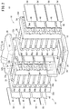
- FIGS. 1 to 3 are a schematic perspective view showing the entirety of a battery pack 10 of this embodiment, a schematic exploded perspective view thereof, and a schematic longitudinal cross section taken along a lengthwise direction thereof, respectively.
- the battery pack 10 includes a case 12 formed like a hollow quadrangular prism having both its ends opened, and a first core pack 14 and a second core pack 16 accommodated in the hollow interior of the case 12.
- the case 12 is manufactured by extrusion molding of a material made of aluminum or aluminum alloy, for example.
- the case 12 can be robust and light in weight, and provides high thermal conductivity and hence superior heat transfer efficiency.
- the case 12 can be manufactured at low cost since the material is low priced.
- the opening at the bottom of the case 12 is closed by a bottom case 18.
- a connector 20 is provided in the bottom of the bottom case 18, where the connector 20 extracts electric power from the first core pack 14 and the second core pack 16 in discharging operation and supplies electric power to the first core pack 14 and the second core pack 16 in charging operation.
- the connector 20 has a positive terminal and a negative terminal (neither of which is shown).
- a battery management unit (BMU) 24 is inserted between the bottom case 18, and the first core pack 14 and the second core pack 16, where the BMU 24 is a control unit for managing temperatures and voltages of the first core pack 14 and the second core pack 16.
- the BMU 24 serves also as a communication unit for performing communications with the external equipment (an electric vehicle etc.) and charger device.
- top opening of the case 12 is closed by a top case 26.
- a handle 28 shaped like an arch is formed on the top case 26, where the user can hold the handle 28 to lift up or carry the battery pack 10.
- the first core pack 14 includes a plurality of unit cells 30 held in a first cell holder 32a and a second cell holder 32b.
- each unit cell 30 is shaped like a cylinder and has a positive electrode and a negative electrode provided at both ends of its axial direction.
- the positive electrode is a first electrode, for example, in which case the negative electrode is a second electrode having the polarity reverse of the positive electrode. Configuration of such unit cells 30 is well known and so the positive electrodes and negative electrodes will not be graphically shown nor described in detail herein.
- a preferred example of the unit cells 30 can be lithium-ion secondary cells, but the unit cells 30 are not particularly limited thereto.
- Other preferred examples include nickel-hydrogen cells, nickel-cadmium cells, etc.
- the first cell holder 32a and the second cell holder 32b have a plurality of storage holes 34a, 34b formed therethrough, respectively.
- the storage holes 34a, 34b are connected to each other as the first cell holder 32a and the second cell holder 32b are joined together.
- the diameter of the storage holes 34a, 34b corresponds to the diameter of the unit cells 30.
- the length of the connected storage holes 34a, 34b corresponds to the height of the unit cells 30.
- the unit cells 30 are arranged in such a manner that their lengthwise direction lies orthogonal to the lengthwise direction (top-bottom direction) of the battery pack 10. In this attitude, the unit cells 30 are individually inserted and held in the storage holes 34a, 34b.
- the unit cells 30 inserted in the storage holes 34a, 34b are arranged in parallel with one another along a widthwise direction that is orthogonal to the lengthwise direction thereof.
- a row of multiple unit cells 30 arranged in the widthwise direction will hereinafter be referred to as a "cell group".
- the unit cells 30 of the lowermost cell group that is located closest to the connector 20 are positioned in such a manner that the negative electrodes thereof face the second core pack 16. Further, in the cell group that is located right above the lowermost one, the unit cells 30 are positioned in such a manner that the positive electrodes thereof face the second core pack 16.
- first cell groups the cell groups including unit cells 30 having negative electrodes facing the second core pack 16
- second cell groups the cell groups including unit cells 30 having positive electrodes facing the second core pack 16
- the cell group located right above the lowermost second cell group is a first cell group, and the cell group located right above this first cell group is a second cell group.
- the first cell groups and the second cell groups are disposed alternately in this way. That is, in adjacent cell groups, electrodes with reverse polarities are directed in the same direction.
- the first core pack 14 includes four first cell groups and three second cell groups.
- the first cell groups will hereinafter be labeled using reference numerals as 40a, 40b, 40c, 40d from bottom to top.
- the second cell groups will be labeled as 42a, 42b, 42c from bottom to top.
- the wording "the positive electrodes (or negative electrodes) of a first cell group” means “the positive electrodes (or negative electrodes) of the unit cells 30 constituting the first cell group”.
- the positive electrodes (or negative electrodes) of a second cell group means “the positive electrodes (or negative electrodes) of the unit cells 30 constituting the second cell group”.
- the positive electrodes of the first cell group 40a that is the lowermost, or closest to the connector 20, are electrically connected to the positive terminal of the connector 20 through a positive-side connection busbar 44.
- the positive-side connection busbar 44 is disposed to face an inner wall of the case 12 and electrically parallel-connects the positive electrodes of the unit cells 30 forming the first cell group 40a.
- the negative electrodes of the first cell group 40a and the positive electrodes of the second cell group 42a are electrically connected in series through a cell group interconnection busbar 46 laid across the adjacent cell groups.
- the cell group interconnection busbar 46 serves also to electrically parallel-connect the negative electrodes of the unit cells 30 forming the first cell group 40a, and the positive electrodes of the unit cells 30 forming the second cell group 42a.
- the negative electrodes of the second cell group 42a and the positive electrodes of the first cell group 40b, the negative electrodes of the first cell group 40b and the positive electrodes of the second cell group 42b, the negative electrodes of the second cell group 42b and the positive electrodes of the first cell group 40c, the negative electrodes of the first cell group 40c and the positive electrodes of the second cell group 42c, and the negative electrodes of the second cell group 42c and the positive electrodes of the first cell group 40d are electrically connected in series respectively through cell group interconnection busbars 46.
- the cell group interconnection busbars 46 each electrically connect the unit cells 30 of the same cell group in parallel.
- the second core pack 16 includes a plurality of unit cells 30 held in a third cell holder 32c and a fourth cell holder 32d. That is, the third cell holder 32c and fourth cell holder 32d have a plurality of storage holes 34c, 34d formed therethrough, respectively.
- the storage holes 34c, 34d are connected to each other as the third cell holder 32c and the fourth cell holder 32d are joined together.
- the unit cells 30 are positioned in such a manner that their lengthwise direction lies orthogonal to the lengthwise direction (top-bottom direction) of the battery pack 10. In this attitude, the unit cells 30 are individually inserted and held in the storage holes 34c, 34d.
- first cell groups the cell groups in which the positive electrodes are directed in the same direction as the positive electrodes of the first cell groups 40a to 40d of the first core pack 14
- second cell groups the cell groups in which the negative electrodes are directed in the same direction as the negative electrodes of the second cell groups 42a to 42c of the first core pack 14
- the positive electrodes of the unit cells 30 forming the first cell groups and the negative electrodes of the unit cells 30 forming the second cell groups face the first core pack 14.
- the lowermost cell group that is located closest to the connector 20 is a first cell group, and the one right above this first cell group is the lowermost second cell group. Also, the one right above this second cell group is a first cell group. That is, the first cell groups and the second cell groups are arranged alternately also in the second core pack 16.
- the second core pack 16 includes four first cell groups and three second cell groups. In order that the cell groups can be identified easily, the first cell groups will hereinafter be labeled using reference numerals as 40e, 40f, 40g, 40h from bottom to top. Also, the second cell groups will be labeled as 42d, 42e, 42f from bottom to top.
- the negative electrodes of the first cell group 40e that is the lowermost, or closest to the connector 20, are electrically connected to the negative terminal of the connector 20 through a negative-side connection busbar 48.
- the negative-side connection busbar 48 is disposed to face an inner wall of the case 12 and electrically parallel-connects the negative electrodes of the unit cells 30 forming the first cell group 40e.
- the positive electrodes of the first cell group 40h located uppermost in the second core pack 16 are electrically series-connected to the negative electrodes of the first cell group 40d located uppermost in the first core pack 14, through a core pack interconnection busbar 50. That is, the core pack interconnection busbar 50 electrically connects the positive electrodes of the first cell group 40h that is most distant from the connector 20 and is located most downstream in the direction in which electrons move (most upstream in the direction in which current flows) in the second core pack 16, and the negative electrodes of the first cell group 40d that is most distant from the connector 20 and is located most upstream in the direction in which electrons move (most downstream in the direction in which current flows) in the first core pack 14.
- the core pack interconnection busbar 50 electrically parallel-connects the positive electrodes of the unit cells 30 of the first cell group 40h, and the negative electrodes of the unit cells 30 of the first cell group 40d.
- the cell group interconnection busbar 46 that connects the first cell group 40e closest to the negative terminal of the connector 20 and the second cell group 42d right above the first cell group 40e presents the lowest potential, for the reason that will be explained later.
- the cell group interconnection busbar 46 that connects the first cell group 40a closest to the positive terminal of the connector 20 and the second cell group 42a right above the first cell group 40a presents the highest potential among all cell group interconnection busbars 46.
- the cell group interconnection busbar 46 with the lowest potential will hereinafter be referred to as "lowest potential busbar 46a", and the cell group interconnection busbar 46 with the highest potential will be referred to as “highest potential busbar 46b”.
- the lowest potential busbar 46a is disposed on the surface of the second core pack 16, the surface facing the first core pack 14.
- the highest potential busbar 46b is disposed on the surface of the first core pack 14, the surface facing the second core pack 16. That is, the lowest potential busbar 46a and the highest potential busbar 46b face each other.
- an inert putty 52 as an insulator is interposed between the lowest potential busbar 46a and the highest potential busbar 46b.
- the inert putty 52 has been hardened, of course, and fills the clearance between the lowest potential busbar 46a and the highest potential busbar 46b.
- the first to fourth cell holders 32a to 32d each have protruding walls to form a frame 54.
- the cell group interconnection busbars 46, most part of the positive-side connection busbar 44, and most part of the negative-side connection busbar 48 are fitted in the frames 54.
- Heat dissipating sheets 56 are interposed as radiating members between inner walls of the case 12 and the cell group interconnection busbars 46 facing the case 12. Material that is sufficiently elastic and that can be kept compressed between the first cell holder 32a or fourth cell holder 32d and the inner wall of the case 12 is selected as a preferable material to form the heat dissipating sheets 56. This is because in this case the heat dissipating sheets 56 can be in close contact in large area with the first core pack 14 or second core pack 16 and the inner wall of the case 12.
- the battery pack 10 according to this embodiment is configured basically as described above, and its functions and effects will be described next.
- the user When installing the battery pack 10 in an external device such as an electric vehicle etc., the user holds the handle 28 and carries the battery pack 10 to that external device, and then installs the battery pack 10 into a battery installation unit of the external device, in such a manner that the connector 20 and the connector of the external device are electrically connected to each other. Since the connector 20 is disposed in the bottom of the bottom case 18 (see FIG. 1 ), the battery pack 10 is usually positioned such that its lengthwise direction lies along the direction of gravity, or such that its lengthwise direction is somewhat inclined relative to the direction of gravity. Then, electric power is supplied from the unit cells 30 in the case 12 to the external device when the starter switch of the external device is turned on. That is, the unit cells 30 discharge.
- vertically adjacent cell groups are electrically connected in series through the cell group interconnection busbars 46.
- the negative electrodes of the first cell group 40e are connected to the negative terminal of the connector 20 through the negative-side connection busbar 48
- the positive electrodes of the first cell group 40a are connected to the positive terminal of the connector 20 through the positive-side connection busbar 44.
- the positive electrodes of the first cell group 40h in the second core pack 16 and the negative electrodes of the first cell group 40d in the first core pack 14 are connected through the core pack interconnection busbar 50.
- the potential is lowest at the cell group interconnection busbar 46 that connects the first cell group 40e closest to the negative terminal of the connector 20 and the second cell group 42d right above the first cell group 40e. That is, the cell group interconnection busbar 46 connecting the first cell group 40e and the second cell group 42d is the lowest potential busbar 46a.
- the potential is highest at the cell group interconnection busbar 46 that connects the first cell group 40a closest to the positive terminal of the connector 20 and the second cell group 42a right above the first cell group 40a, among all cell group interconnection busbars 46. That is, the cell group interconnection busbar 46 connecting the first cell group 40a and the second cell group 42a is the highest potential busbar 46b.
- the potential difference between mutually facing cell group interconnection busbars 46 becomes smaller in the direction away from the connector 20.
- the inert putty 52 (insulator) is interposed between the lowest potential busbar 46a and the highest potential busbar 46b. This avoids situations where a short-circuit current flows between the lowest potential busbar 46a and the highest potential busbar 46b. That is, inserting the insulator between the lowest potential busbar 46a and the highest potential busbar 46b eliminates the fear that a short circuit might occur between the two busbars 46a and 46b.
- the potential differences between the cell group interconnection busbars 46 disposed above the busbars 46a and 46b are not very large. Accordingly, even if a short-circuit current flows between the cell group interconnection busbars 46 between which the inert putty 52 is not interposed, the current value thereof is small. That is, the short-circuit current flowing through the unit cells 30 is sufficiently suppressed. The amount of heat generated by the unit cells 30 is therefore small. It is therefore possible to avoid excessive increase in the temperature of the unit cells 30 and hence of the battery pack 10.
- the inert putty 52 is low priced and easily available, and offers superior sealing capability and is hence expected to check entering water. Furthermore, the inert putty 52 itself is physically and chemically stable to water. The short circuit preventing effect and sealing effect can therefore be sustained for a long period of time.
- the present invention is not particularly limited to the embodiments described above but can be modified in various manners without departing from the essence and gist of the present invention.
- the negative electrodes of the unit cells 30 may be first electrodes and the positive electrodes thereof may be second electrodes.
- the insulator is not particularly limited to the inert putty 52 but can be resin etc.
- Insulator may be provided not only between the lowest potential busbar 46a and the highest potential busbar 46b where the potential difference is largest, but also in other portions where short circuit may possibly occur. Such a place can be the clearance between the cell group interconnection busbars 46, 46 with the next largest potential difference, i.e., between the cell group interconnection busbar 46 right above the lowest potential busbar 46a and the cell group interconnection busbar 46 right above the highest potential busbar 46b. Insulator may be provided between other cell group interconnection busbars 46, 46 where necessary.
- a battery pack (10) includes a first core pack (14) and a second core pack (16) each holding a plurality of unit cells (30).
- the unit cells (30) of one of first cell groups (or second cell groups) in each of the first core pack (14) and the second core pack (16) are electrically connected to a connector (20) through a positive-side connection busbar (44) and a negative-side connection busbar (48), respectively.
- Vertically adjacent cell groups are electrically connected to each other through cell group interconnection busbars (46).
- Insulator (52) is interposed between the mutually facing cell group interconnection busbars (46) that present a largest potential difference.
Applications Claiming Priority (1)
| Application Number | Priority Date | Filing Date | Title |
|---|---|---|---|
| JP2019104146A JP6790176B1 (ja) | 2019-06-04 | 2019-06-04 | バッテリパック |
Publications (2)
| Publication Number | Publication Date |
|---|---|
| EP3748725A1 true EP3748725A1 (fr) | 2020-12-09 |
| EP3748725B1 EP3748725B1 (fr) | 2021-12-08 |
Family
ID=70977373
Family Applications (1)
| Application Number | Title | Priority Date | Filing Date |
|---|---|---|---|
| EP20177941.0A Active EP3748725B1 (fr) | 2019-06-04 | 2020-06-03 | Bloc-batterie |
Country Status (5)
| Country | Link |
|---|---|
| US (1) | US11088421B2 (fr) |
| EP (1) | EP3748725B1 (fr) |
| JP (1) | JP6790176B1 (fr) |
| CN (1) | CN112038515B (fr) |
| AU (1) | AU2020203663A1 (fr) |
Cited By (1)
| Publication number | Priority date | Publication date | Assignee | Title |
|---|---|---|---|---|
| WO2021254845A1 (fr) * | 2020-06-19 | 2021-12-23 | Robert Bosch Gmbh | Module de batterie, son procédé de production et son utilisation |
Families Citing this family (1)
| Publication number | Priority date | Publication date | Assignee | Title |
|---|---|---|---|---|
| CN115425349B (zh) * | 2022-09-19 | 2023-12-26 | 苏州极目机器人科技有限公司 | 一种电池组件 |
Citations (6)
| Publication number | Priority date | Publication date | Assignee | Title |
|---|---|---|---|---|
| JP2011216366A (ja) | 2010-03-31 | 2011-10-27 | Sanyo Electric Co Ltd | バッテリパック |
| EP2685543A1 (fr) * | 2012-07-10 | 2014-01-15 | Lite-On Clean Energy Technology Corp. | Bloc batterie |
| CN106058112A (zh) * | 2016-08-12 | 2016-10-26 | 东莞力朗电池科技有限公司 | 一种圆柱型电池模组 |
| US20160336572A1 (en) * | 2014-01-23 | 2016-11-17 | Sony Corporation | Power storage device, power storage system, electronic device, electric vehicle, and power system |
| WO2017062886A1 (fr) * | 2015-10-08 | 2017-04-13 | Cellink Corporation | Interconnexions de batteries |
| WO2020032081A1 (fr) * | 2018-08-07 | 2020-02-13 | 本田技研工業株式会社 | Bloc-batterie |
Family Cites Families (15)
| Publication number | Priority date | Publication date | Assignee | Title |
|---|---|---|---|---|
| KR100984005B1 (ko) * | 2005-09-22 | 2010-09-30 | 구라레 케미칼 가부시키가이샤 | 분극성 전극 및 전기 이중층 캐패시터 |
| DE102011002452A1 (de) * | 2011-01-05 | 2012-07-05 | Sb Limotive Company Ltd. | Batterie mit autonomem Cell-Balancing |
| JP5309278B1 (ja) * | 2011-12-09 | 2013-10-09 | 本田技研工業株式会社 | 電動車両の充電装置 |
| US10454078B2 (en) * | 2012-08-30 | 2019-10-22 | The Chemours Company Fc, Llc | Li-ion battery having improved safety against combustion |
| TW201633585A (zh) * | 2014-12-15 | 2016-09-16 | A123系統有限責任公司 | 電池總成、電池系統以及車輛電池 |
| US10256511B2 (en) * | 2015-05-28 | 2019-04-09 | Bren-Tronics, Inc. | Secondary battery housing with control electronics |
| KR101958762B1 (ko) * | 2015-07-17 | 2019-03-15 | 주식회사 엘지화학 | 원통형 이차전지 |
| US10566652B2 (en) * | 2017-08-15 | 2020-02-18 | GM Global Technology Operations LLC | Lithium metal battery with hybrid electrolyte system |
| JP2019067559A (ja) * | 2017-09-29 | 2019-04-25 | 本田技研工業株式会社 | バッテリパック |
| JP7064842B2 (ja) * | 2017-09-29 | 2022-05-11 | 本田技研工業株式会社 | バッテリパック |
| CN107742685B (zh) * | 2017-10-12 | 2023-12-05 | 苏州达方电子有限公司 | 一种电池模组 |
| KR102444124B1 (ko) | 2017-10-16 | 2022-09-16 | 주식회사 엘지에너지솔루션 | 배터리 모듈 및 이를 포함하는 배터리 팩 |
| JP2019169337A (ja) * | 2018-03-23 | 2019-10-03 | 本田技研工業株式会社 | バッテリパック |
| CN109066917A (zh) * | 2018-09-28 | 2018-12-21 | 北京新能源汽车股份有限公司 | 一种电池系统及充电方法 |
| CN209169564U (zh) * | 2019-01-23 | 2019-07-26 | 宁德时代新能源科技股份有限公司 | 汇流条组件及电池模组 |
-
2019
- 2019-06-04 JP JP2019104146A patent/JP6790176B1/ja active Active
-
2020
- 2020-06-02 US US16/889,976 patent/US11088421B2/en active Active
- 2020-06-03 AU AU2020203663A patent/AU2020203663A1/en active Pending
- 2020-06-03 EP EP20177941.0A patent/EP3748725B1/fr active Active
- 2020-06-04 CN CN202010499684.XA patent/CN112038515B/zh active Active
Patent Citations (6)
| Publication number | Priority date | Publication date | Assignee | Title |
|---|---|---|---|---|
| JP2011216366A (ja) | 2010-03-31 | 2011-10-27 | Sanyo Electric Co Ltd | バッテリパック |
| EP2685543A1 (fr) * | 2012-07-10 | 2014-01-15 | Lite-On Clean Energy Technology Corp. | Bloc batterie |
| US20160336572A1 (en) * | 2014-01-23 | 2016-11-17 | Sony Corporation | Power storage device, power storage system, electronic device, electric vehicle, and power system |
| WO2017062886A1 (fr) * | 2015-10-08 | 2017-04-13 | Cellink Corporation | Interconnexions de batteries |
| CN106058112A (zh) * | 2016-08-12 | 2016-10-26 | 东莞力朗电池科技有限公司 | 一种圆柱型电池模组 |
| WO2020032081A1 (fr) * | 2018-08-07 | 2020-02-13 | 本田技研工業株式会社 | Bloc-batterie |
Cited By (1)
| Publication number | Priority date | Publication date | Assignee | Title |
|---|---|---|---|---|
| WO2021254845A1 (fr) * | 2020-06-19 | 2021-12-23 | Robert Bosch Gmbh | Module de batterie, son procédé de production et son utilisation |
Also Published As
| Publication number | Publication date |
|---|---|
| EP3748725B1 (fr) | 2021-12-08 |
| CN112038515A (zh) | 2020-12-04 |
| US20200388816A1 (en) | 2020-12-10 |
| JP2020198230A (ja) | 2020-12-10 |
| CN112038515B (zh) | 2024-01-19 |
| US11088421B2 (en) | 2021-08-10 |
| AU2020203663A1 (en) | 2020-12-24 |
| JP6790176B1 (ja) | 2020-11-25 |
Similar Documents
| Publication | Publication Date | Title |
|---|---|---|
| US9203075B2 (en) | Battery pack including overcurrent protector | |
| US20120156537A1 (en) | Electrochemical energy storage device | |
| US20120328908A1 (en) | Battery Pack | |
| EP2079145A2 (fr) | Chargeur pour blocs-batteries et combinaison de blocs-batteries et d'un chargeur | |
| US10559804B2 (en) | Battery pack | |
| EP3748725A1 (fr) | Bloc-batterie | |
| KR102047481B1 (ko) | 배터리 모듈 및 이를 포함하는 배터리 팩 | |
| KR101465168B1 (ko) | 케이블형 이차전지 | |
| KR20200021791A (ko) | 버스바 플레이트를 포함하는 배터리 모듈 | |
| EP3579297A1 (fr) | Bloc d'éléments | |
| EP3748724B1 (fr) | Bloc-batterie | |
| KR20200020565A (ko) | 조립 구조가 개선된 배터리관리시스템을 포함한 배터리모듈 | |
| EP3367463A2 (fr) | Module de batterie, bloc-batterie et véhicule le comprenant | |
| KR102459622B1 (ko) | 배터리 팩 | |
| JP7157706B2 (ja) | バッテリパック | |
| EP3255702A1 (fr) | Bloc-piles | |
| US20100136403A1 (en) | Electric facility operating according to galvanic principles | |
| JP7227078B2 (ja) | バッテリパック | |
| CN108063193B (zh) | 具有等电阻充放电路径的电池并联装置 | |
| KR20200076909A (ko) | 조립 구조가 개선되고 멀티셀렉팅 기능의 배터리관리시스템을 포함한 배터리팩 | |
| KR102307906B1 (ko) | 방열구조를 갖는 배터리 팩 | |
| KR20190042342A (ko) | 배터리 모듈 및 배터리 팩 | |
| EP4360945A2 (fr) | Module de stockage d'énergie de véhicule, bloc-batterie et véhicule | |
| US20160226052A1 (en) | Secondary battery | |
| KR101545690B1 (ko) | 케이블형 이차전지 |
Legal Events
| Date | Code | Title | Description |
|---|---|---|---|
| PUAI | Public reference made under article 153(3) epc to a published international application that has entered the european phase |
Free format text: ORIGINAL CODE: 0009012 |
|
| STAA | Information on the status of an ep patent application or granted ep patent |
Free format text: STATUS: THE APPLICATION HAS BEEN PUBLISHED |
|
| AK | Designated contracting states |
Kind code of ref document: A1 Designated state(s): AL AT BE BG CH CY CZ DE DK EE ES FI FR GB GR HR HU IE IS IT LI LT LU LV MC MK MT NL NO PL PT RO RS SE SI SK SM TR |
|
| AX | Request for extension of the european patent |
Extension state: BA ME |
|
| STAA | Information on the status of an ep patent application or granted ep patent |
Free format text: STATUS: REQUEST FOR EXAMINATION WAS MADE |
|
| 17P | Request for examination filed |
Effective date: 20210329 |
|
| RBV | Designated contracting states (corrected) |
Designated state(s): AL AT BE BG CH CY CZ DE DK EE ES FI FR GB GR HR HU IE IS IT LI LT LU LV MC MK MT NL NO PL PT RO RS SE SI SK SM TR |
|
| REG | Reference to a national code |
Ref country code: DE Ref legal event code: R079 Ref document number: 602020001217 Country of ref document: DE Free format text: PREVIOUS MAIN CLASS: H01M0002100000 Ipc: H01M0050200000 |
|
| GRAP | Despatch of communication of intention to grant a patent |
Free format text: ORIGINAL CODE: EPIDOSNIGR1 |
|
| STAA | Information on the status of an ep patent application or granted ep patent |
Free format text: STATUS: GRANT OF PATENT IS INTENDED |
|
| RIC1 | Information provided on ipc code assigned before grant |
Ipc: H01M 50/20 20210101AFI20210705BHEP |
|
| INTG | Intention to grant announced |
Effective date: 20210727 |
|
| GRAS | Grant fee paid |
Free format text: ORIGINAL CODE: EPIDOSNIGR3 |
|
| GRAA | (expected) grant |
Free format text: ORIGINAL CODE: 0009210 |
|
| STAA | Information on the status of an ep patent application or granted ep patent |
Free format text: STATUS: THE PATENT HAS BEEN GRANTED |
|
| AK | Designated contracting states |
Kind code of ref document: B1 Designated state(s): AL AT BE BG CH CY CZ DE DK EE ES FI FR GB GR HR HU IE IS IT LI LT LU LV MC MK MT NL NO PL PT RO RS SE SI SK SM TR |
|
| REG | Reference to a national code |
Ref country code: GB Ref legal event code: FG4D |
|
| REG | Reference to a national code |
Ref country code: AT Ref legal event code: REF Ref document number: 1454443 Country of ref document: AT Kind code of ref document: T Effective date: 20211215 Ref country code: CH Ref legal event code: EP |
|
| REG | Reference to a national code |
Ref country code: DE Ref legal event code: R096 Ref document number: 602020001217 Country of ref document: DE |
|
| REG | Reference to a national code |
Ref country code: IE Ref legal event code: FG4D |
|
| REG | Reference to a national code |
Ref country code: LT Ref legal event code: MG9D |
|
| REG | Reference to a national code |
Ref country code: NL Ref legal event code: MP Effective date: 20211208 |
|
| PG25 | Lapsed in a contracting state [announced via postgrant information from national office to epo] |
Ref country code: RS Free format text: LAPSE BECAUSE OF FAILURE TO SUBMIT A TRANSLATION OF THE DESCRIPTION OR TO PAY THE FEE WITHIN THE PRESCRIBED TIME-LIMIT Effective date: 20211208 Ref country code: LT Free format text: LAPSE BECAUSE OF FAILURE TO SUBMIT A TRANSLATION OF THE DESCRIPTION OR TO PAY THE FEE WITHIN THE PRESCRIBED TIME-LIMIT Effective date: 20211208 Ref country code: FI Free format text: LAPSE BECAUSE OF FAILURE TO SUBMIT A TRANSLATION OF THE DESCRIPTION OR TO PAY THE FEE WITHIN THE PRESCRIBED TIME-LIMIT Effective date: 20211208 Ref country code: BG Free format text: LAPSE BECAUSE OF FAILURE TO SUBMIT A TRANSLATION OF THE DESCRIPTION OR TO PAY THE FEE WITHIN THE PRESCRIBED TIME-LIMIT Effective date: 20220308 |
|
| REG | Reference to a national code |
Ref country code: AT Ref legal event code: MK05 Ref document number: 1454443 Country of ref document: AT Kind code of ref document: T Effective date: 20211208 |
|
| PG25 | Lapsed in a contracting state [announced via postgrant information from national office to epo] |
Ref country code: SE Free format text: LAPSE BECAUSE OF FAILURE TO SUBMIT A TRANSLATION OF THE DESCRIPTION OR TO PAY THE FEE WITHIN THE PRESCRIBED TIME-LIMIT Effective date: 20211208 Ref country code: NO Free format text: LAPSE BECAUSE OF FAILURE TO SUBMIT A TRANSLATION OF THE DESCRIPTION OR TO PAY THE FEE WITHIN THE PRESCRIBED TIME-LIMIT Effective date: 20220308 Ref country code: LV Free format text: LAPSE BECAUSE OF FAILURE TO SUBMIT A TRANSLATION OF THE DESCRIPTION OR TO PAY THE FEE WITHIN THE PRESCRIBED TIME-LIMIT Effective date: 20211208 Ref country code: HR Free format text: LAPSE BECAUSE OF FAILURE TO SUBMIT A TRANSLATION OF THE DESCRIPTION OR TO PAY THE FEE WITHIN THE PRESCRIBED TIME-LIMIT Effective date: 20211208 Ref country code: GR Free format text: LAPSE BECAUSE OF FAILURE TO SUBMIT A TRANSLATION OF THE DESCRIPTION OR TO PAY THE FEE WITHIN THE PRESCRIBED TIME-LIMIT Effective date: 20220309 |
|
| PG25 | Lapsed in a contracting state [announced via postgrant information from national office to epo] |
Ref country code: NL Free format text: LAPSE BECAUSE OF FAILURE TO SUBMIT A TRANSLATION OF THE DESCRIPTION OR TO PAY THE FEE WITHIN THE PRESCRIBED TIME-LIMIT Effective date: 20211208 |
|
| PG25 | Lapsed in a contracting state [announced via postgrant information from national office to epo] |
Ref country code: SM Free format text: LAPSE BECAUSE OF FAILURE TO SUBMIT A TRANSLATION OF THE DESCRIPTION OR TO PAY THE FEE WITHIN THE PRESCRIBED TIME-LIMIT Effective date: 20211208 Ref country code: SK Free format text: LAPSE BECAUSE OF FAILURE TO SUBMIT A TRANSLATION OF THE DESCRIPTION OR TO PAY THE FEE WITHIN THE PRESCRIBED TIME-LIMIT Effective date: 20211208 Ref country code: RO Free format text: LAPSE BECAUSE OF FAILURE TO SUBMIT A TRANSLATION OF THE DESCRIPTION OR TO PAY THE FEE WITHIN THE PRESCRIBED TIME-LIMIT Effective date: 20211208 Ref country code: PT Free format text: LAPSE BECAUSE OF FAILURE TO SUBMIT A TRANSLATION OF THE DESCRIPTION OR TO PAY THE FEE WITHIN THE PRESCRIBED TIME-LIMIT Effective date: 20220408 Ref country code: ES Free format text: LAPSE BECAUSE OF FAILURE TO SUBMIT A TRANSLATION OF THE DESCRIPTION OR TO PAY THE FEE WITHIN THE PRESCRIBED TIME-LIMIT Effective date: 20211208 Ref country code: EE Free format text: LAPSE BECAUSE OF FAILURE TO SUBMIT A TRANSLATION OF THE DESCRIPTION OR TO PAY THE FEE WITHIN THE PRESCRIBED TIME-LIMIT Effective date: 20211208 Ref country code: CZ Free format text: LAPSE BECAUSE OF FAILURE TO SUBMIT A TRANSLATION OF THE DESCRIPTION OR TO PAY THE FEE WITHIN THE PRESCRIBED TIME-LIMIT Effective date: 20211208 |
|
| PG25 | Lapsed in a contracting state [announced via postgrant information from national office to epo] |
Ref country code: PL Free format text: LAPSE BECAUSE OF FAILURE TO SUBMIT A TRANSLATION OF THE DESCRIPTION OR TO PAY THE FEE WITHIN THE PRESCRIBED TIME-LIMIT Effective date: 20211208 Ref country code: AT Free format text: LAPSE BECAUSE OF FAILURE TO SUBMIT A TRANSLATION OF THE DESCRIPTION OR TO PAY THE FEE WITHIN THE PRESCRIBED TIME-LIMIT Effective date: 20211208 |
|
| REG | Reference to a national code |
Ref country code: DE Ref legal event code: R097 Ref document number: 602020001217 Country of ref document: DE |
|
| PG25 | Lapsed in a contracting state [announced via postgrant information from national office to epo] |
Ref country code: IS Free format text: LAPSE BECAUSE OF FAILURE TO SUBMIT A TRANSLATION OF THE DESCRIPTION OR TO PAY THE FEE WITHIN THE PRESCRIBED TIME-LIMIT Effective date: 20220408 |
|
| PLBE | No opposition filed within time limit |
Free format text: ORIGINAL CODE: 0009261 |
|
| STAA | Information on the status of an ep patent application or granted ep patent |
Free format text: STATUS: NO OPPOSITION FILED WITHIN TIME LIMIT |
|
| PG25 | Lapsed in a contracting state [announced via postgrant information from national office to epo] |
Ref country code: DK Free format text: LAPSE BECAUSE OF FAILURE TO SUBMIT A TRANSLATION OF THE DESCRIPTION OR TO PAY THE FEE WITHIN THE PRESCRIBED TIME-LIMIT Effective date: 20211208 Ref country code: AL Free format text: LAPSE BECAUSE OF FAILURE TO SUBMIT A TRANSLATION OF THE DESCRIPTION OR TO PAY THE FEE WITHIN THE PRESCRIBED TIME-LIMIT Effective date: 20211208 |
|
| 26N | No opposition filed |
Effective date: 20220909 |
|
| PG25 | Lapsed in a contracting state [announced via postgrant information from national office to epo] |
Ref country code: SI Free format text: LAPSE BECAUSE OF FAILURE TO SUBMIT A TRANSLATION OF THE DESCRIPTION OR TO PAY THE FEE WITHIN THE PRESCRIBED TIME-LIMIT Effective date: 20211208 |
|
| PG25 | Lapsed in a contracting state [announced via postgrant information from national office to epo] |
Ref country code: MC Free format text: LAPSE BECAUSE OF FAILURE TO SUBMIT A TRANSLATION OF THE DESCRIPTION OR TO PAY THE FEE WITHIN THE PRESCRIBED TIME-LIMIT Effective date: 20211208 |
|
| REG | Reference to a national code |
Ref country code: BE Ref legal event code: MM Effective date: 20220630 |
|
| PG25 | Lapsed in a contracting state [announced via postgrant information from national office to epo] |
Ref country code: LU Free format text: LAPSE BECAUSE OF NON-PAYMENT OF DUE FEES Effective date: 20220603 Ref country code: IE Free format text: LAPSE BECAUSE OF NON-PAYMENT OF DUE FEES Effective date: 20220603 Ref country code: FR Free format text: LAPSE BECAUSE OF NON-PAYMENT OF DUE FEES Effective date: 20220630 |
|
| PG25 | Lapsed in a contracting state [announced via postgrant information from national office to epo] |
Ref country code: BE Free format text: LAPSE BECAUSE OF NON-PAYMENT OF DUE FEES Effective date: 20220630 |
|
| REG | Reference to a national code |
Ref country code: DE Ref legal event code: R084 Ref document number: 602020001217 Country of ref document: DE |
|
| PGFP | Annual fee paid to national office [announced via postgrant information from national office to epo] |
Ref country code: DE Payment date: 20230412 Year of fee payment: 4 |
|
| PGFP | Annual fee paid to national office [announced via postgrant information from national office to epo] |
Ref country code: IT Payment date: 20230630 Year of fee payment: 4 |
|
| REG | Reference to a national code |
Ref country code: CH Ref legal event code: PL |