EP3748102A2 - Betonbauelement mit integrierten ankern - Google Patents
Betonbauelement mit integrierten ankern Download PDFInfo
- Publication number
- EP3748102A2 EP3748102A2 EP20275104.6A EP20275104A EP3748102A2 EP 3748102 A2 EP3748102 A2 EP 3748102A2 EP 20275104 A EP20275104 A EP 20275104A EP 3748102 A2 EP3748102 A2 EP 3748102A2
- Authority
- EP
- European Patent Office
- Prior art keywords
- anchors
- cladding
- machine
- anchor
- concrete
- Prior art date
- Legal status (The legal status is an assumption and is not a legal conclusion. Google has not performed a legal analysis and makes no representation as to the accuracy of the status listed.)
- Granted
Links
Images


Classifications
-
- E—FIXED CONSTRUCTIONS
- E04—BUILDING
- E04F—FINISHING WORK ON BUILDINGS, e.g. STAIRS, FLOORS
- E04F13/00—Coverings or linings, e.g. for walls or ceilings
- E04F13/07—Coverings or linings, e.g. for walls or ceilings composed of covering or lining elements; Sub-structures therefor; Fastening means therefor
- E04F13/08—Coverings or linings, e.g. for walls or ceilings composed of covering or lining elements; Sub-structures therefor; Fastening means therefor composed of a plurality of similar covering or lining elements
- E04F13/0801—Separate fastening elements
- E04F13/0832—Separate fastening elements without load-supporting elongated furring elements between wall and covering elements
- E04F13/0833—Separate fastening elements without load-supporting elongated furring elements between wall and covering elements not adjustable
-
- E—FIXED CONSTRUCTIONS
- E04—BUILDING
- E04C—STRUCTURAL ELEMENTS; BUILDING MATERIALS
- E04C2/00—Building elements of relatively thin form for the construction of parts of buildings, e.g. sheet materials, slabs, or panels
- E04C2/02—Building elements of relatively thin form for the construction of parts of buildings, e.g. sheet materials, slabs, or panels characterised by specified materials
- E04C2/04—Building elements of relatively thin form for the construction of parts of buildings, e.g. sheet materials, slabs, or panels characterised by specified materials of concrete or other stone-like material; of asbestos cement; of cement and other mineral fibres
- E04C2/044—Building elements of relatively thin form for the construction of parts of buildings, e.g. sheet materials, slabs, or panels characterised by specified materials of concrete or other stone-like material; of asbestos cement; of cement and other mineral fibres of concrete
-
- E—FIXED CONSTRUCTIONS
- E04—BUILDING
- E04F—FINISHING WORK ON BUILDINGS, e.g. STAIRS, FLOORS
- E04F13/00—Coverings or linings, e.g. for walls or ceilings
- E04F13/07—Coverings or linings, e.g. for walls or ceilings composed of covering or lining elements; Sub-structures therefor; Fastening means therefor
- E04F13/08—Coverings or linings, e.g. for walls or ceilings composed of covering or lining elements; Sub-structures therefor; Fastening means therefor composed of a plurality of similar covering or lining elements
- E04F13/14—Coverings or linings, e.g. for walls or ceilings composed of covering or lining elements; Sub-structures therefor; Fastening means therefor composed of a plurality of similar covering or lining elements stone or stone-like materials, e.g. ceramics concrete; of glass or with an outer layer of stone or stone-like materials or glass
- E04F13/141—Coverings or linings, e.g. for walls or ceilings composed of covering or lining elements; Sub-structures therefor; Fastening means therefor composed of a plurality of similar covering or lining elements stone or stone-like materials, e.g. ceramics concrete; of glass or with an outer layer of stone or stone-like materials or glass with an outer layer of concrete
-
- B—PERFORMING OPERATIONS; TRANSPORTING
- B28—WORKING CEMENT, CLAY, OR STONE
- B28B—SHAPING CLAY OR OTHER CERAMIC COMPOSITIONS; SHAPING SLAG; SHAPING MIXTURES CONTAINING CEMENTITIOUS MATERIAL, e.g. PLASTER
- B28B23/00—Arrangements specially adapted for the production of shaped articles with elements wholly or partly embedded in the moulding material; Production of reinforced objects
- B28B23/005—Arrangements specially adapted for the production of shaped articles with elements wholly or partly embedded in the moulding material; Production of reinforced objects with anchoring or fastening elements for the shaped articles
-
- B—PERFORMING OPERATIONS; TRANSPORTING
- B28—WORKING CEMENT, CLAY, OR STONE
- B28B—SHAPING CLAY OR OTHER CERAMIC COMPOSITIONS; SHAPING SLAG; SHAPING MIXTURES CONTAINING CEMENTITIOUS MATERIAL, e.g. PLASTER
- B28B23/00—Arrangements specially adapted for the production of shaped articles with elements wholly or partly embedded in the moulding material; Production of reinforced objects
- B28B23/0056—Means for inserting the elements into the mould or supporting them in the mould
-
- B—PERFORMING OPERATIONS; TRANSPORTING
- B28—WORKING CEMENT, CLAY, OR STONE
- B28B—SHAPING CLAY OR OTHER CERAMIC COMPOSITIONS; SHAPING SLAG; SHAPING MIXTURES CONTAINING CEMENTITIOUS MATERIAL, e.g. PLASTER
- B28B23/00—Arrangements specially adapted for the production of shaped articles with elements wholly or partly embedded in the moulding material; Production of reinforced objects
- B28B23/0062—Arrangements specially adapted for the production of shaped articles with elements wholly or partly embedded in the moulding material; Production of reinforced objects forcing the elements into the cast material, e.g. hooks into cast concrete
-
- B—PERFORMING OPERATIONS; TRANSPORTING
- B28—WORKING CEMENT, CLAY, OR STONE
- B28B—SHAPING CLAY OR OTHER CERAMIC COMPOSITIONS; SHAPING SLAG; SHAPING MIXTURES CONTAINING CEMENTITIOUS MATERIAL, e.g. PLASTER
- B28B5/00—Producing shaped articles from the material in moulds or on moulding surfaces, carried or formed by, in or on conveyors irrespective of the manner of shaping
- B28B5/04—Producing shaped articles from the material in moulds or on moulding surfaces, carried or formed by, in or on conveyors irrespective of the manner of shaping in moulds moved in succession past one or more shaping stations
-
- B—PERFORMING OPERATIONS; TRANSPORTING
- B28—WORKING CEMENT, CLAY, OR STONE
- B28B—SHAPING CLAY OR OTHER CERAMIC COMPOSITIONS; SHAPING SLAG; SHAPING MIXTURES CONTAINING CEMENTITIOUS MATERIAL, e.g. PLASTER
- B28B5/00—Producing shaped articles from the material in moulds or on moulding surfaces, carried or formed by, in or on conveyors irrespective of the manner of shaping
- B28B5/06—Producing shaped articles from the material in moulds or on moulding surfaces, carried or formed by, in or on conveyors irrespective of the manner of shaping in moulds on a turntable
- B28B5/08—Producing shaped articles from the material in moulds or on moulding surfaces, carried or formed by, in or on conveyors irrespective of the manner of shaping in moulds on a turntable intermittently rotated
-
- E—FIXED CONSTRUCTIONS
- E04—BUILDING
- E04B—GENERAL BUILDING CONSTRUCTIONS; WALLS, e.g. PARTITIONS; ROOFS; FLOORS; CEILINGS; INSULATION OR OTHER PROTECTION OF BUILDINGS
- E04B1/00—Constructions in general; Structures which are not restricted either to walls, e.g. partitions, or floors or ceilings or roofs
- E04B1/38—Connections for building structures in general
- E04B1/41—Connecting devices specially adapted for embedding in concrete or masonry
-
- E—FIXED CONSTRUCTIONS
- E04—BUILDING
- E04F—FINISHING WORK ON BUILDINGS, e.g. STAIRS, FLOORS
- E04F13/00—Coverings or linings, e.g. for walls or ceilings
- E04F13/07—Coverings or linings, e.g. for walls or ceilings composed of covering or lining elements; Sub-structures therefor; Fastening means therefor
- E04F13/08—Coverings or linings, e.g. for walls or ceilings composed of covering or lining elements; Sub-structures therefor; Fastening means therefor composed of a plurality of similar covering or lining elements
- E04F13/14—Coverings or linings, e.g. for walls or ceilings composed of covering or lining elements; Sub-structures therefor; Fastening means therefor composed of a plurality of similar covering or lining elements stone or stone-like materials, e.g. ceramics concrete; of glass or with an outer layer of stone or stone-like materials or glass
- E04F13/147—Coverings or linings, e.g. for walls or ceilings composed of covering or lining elements; Sub-structures therefor; Fastening means therefor composed of a plurality of similar covering or lining elements stone or stone-like materials, e.g. ceramics concrete; of glass or with an outer layer of stone or stone-like materials or glass with an outer layer imitating natural stone, brick work or the like
-
- E—FIXED CONSTRUCTIONS
- E04—BUILDING
- E04F—FINISHING WORK ON BUILDINGS, e.g. STAIRS, FLOORS
- E04F13/00—Coverings or linings, e.g. for walls or ceilings
- E04F13/07—Coverings or linings, e.g. for walls or ceilings composed of covering or lining elements; Sub-structures therefor; Fastening means therefor
- E04F13/08—Coverings or linings, e.g. for walls or ceilings composed of covering or lining elements; Sub-structures therefor; Fastening means therefor composed of a plurality of similar covering or lining elements
- E04F13/0801—Separate fastening elements
- E04F13/0803—Separate fastening elements with load-supporting elongated furring elements between wall and covering elements
- E04F13/081—Separate fastening elements with load-supporting elongated furring elements between wall and covering elements with additional fastening elements between furring elements and covering elements
- E04F13/083—Hooking means on the back side of the covering elements
-
- E—FIXED CONSTRUCTIONS
- E04—BUILDING
- E04F—FINISHING WORK ON BUILDINGS, e.g. STAIRS, FLOORS
- E04F13/00—Coverings or linings, e.g. for walls or ceilings
- E04F13/07—Coverings or linings, e.g. for walls or ceilings composed of covering or lining elements; Sub-structures therefor; Fastening means therefor
- E04F13/08—Coverings or linings, e.g. for walls or ceilings composed of covering or lining elements; Sub-structures therefor; Fastening means therefor composed of a plurality of similar covering or lining elements
- E04F13/0862—Coverings or linings, e.g. for walls or ceilings composed of covering or lining elements; Sub-structures therefor; Fastening means therefor composed of a plurality of similar covering or lining elements composed of a number of elements which are identical or not, e.g. carried by a common web, support plate or grid
-
- E—FIXED CONSTRUCTIONS
- E04—BUILDING
- E04F—FINISHING WORK ON BUILDINGS, e.g. STAIRS, FLOORS
- E04F13/00—Coverings or linings, e.g. for walls or ceilings
- E04F13/07—Coverings or linings, e.g. for walls or ceilings composed of covering or lining elements; Sub-structures therefor; Fastening means therefor
- E04F13/08—Coverings or linings, e.g. for walls or ceilings composed of covering or lining elements; Sub-structures therefor; Fastening means therefor composed of a plurality of similar covering or lining elements
- E04F13/0885—Coverings or linings, e.g. for walls or ceilings composed of covering or lining elements; Sub-structures therefor; Fastening means therefor composed of a plurality of similar covering or lining elements specially adapted for being adhesively fixed to the wall; Fastening means therefor; Fixing by means of plastics materials hardening after application
Definitions
- the present invention pertains to cladding element for walls of buildings. Particularly, the present invention pertains to improved integrated machinery, means and methods for manufacturing covering elements for walls of buildings with concrete cladding blocks and a plurality of embedded anchors in predetermined configuration, number and distribution.
- an object of the present invention to provide integrated machinery for manufacturing cladding elements that comprise advance embedded anchors in predetermined number, distribution and configuration for fixing to a construction wall in a plant or onsite.
- the present invention pertains to integrated machine for manufacturing anchor embedded cladding elements.
- this machine comprises a cladding block manufacturing machine and anchor feeding and embedding machine, where the concrete block manufacturing machine and anchor feeding and embedding machine are configured for coordinated operation for producing anchors embedded cladding elements comprising concrete blocks and anchors embedded within said blocks.
- the flexibility and versatility of the machine is in determining the end location of the anchors in the final cladding element before even manufacturing the cladding block. This provides greater degree of freedom, which in turn allows increasing the strength in fixing the cladding elements to a support wall on the one hand, and decreasing onsite or prefabrication workload and difficulties in the cladding process, and ensures that all anchors needed are there.
- the anchors used are essentially three parts, one longer and one shorter legs and a bendable axis connecting them. This structure allows bending the anchors in 90° position between the legs and sticking them into freshly manufactured concrete cladd blocks. Then dedicated device may be used to lift the exposed leg, which is usually the longer one, up and use it to connect to a support wall through mediating elements, namely a steel net and cement poured in the space between the cladding elements and the wall.
- the degrees of freedom in determining the number, distribution and configuration of the anchors in advance provide improved strength in fixing the cladding elements to a support wall and versatility and flexibility in adapting the required strength under varying conditions, including weather changes, gradual erosion, seismographic activity and general environmental conditions.
- the machinery of the present invention is based on machinery for producing cladding blocks and an adaptable machine for arranging, mounting, loading, delivering and embedding anchors in the cladding blocks.
- Such integrated machinery requires that these two modules operate in coordination with each other.
- the anchor related module is also adaptable to custom machines for manufacturing cladding blocks and may be arranged to work with them from mechanic and timing perspectives.
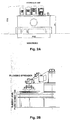
- Fig. 1 schematically illustrates an exemplary Hermetic Press machine 100 for manufacturing concrete cladding blocks/elements.
- This machine operates in simultaneous multi-stage production of the blocks, using a revolving table with multiple trays that carry a plurality of plates for manufacturing the cladding blocks/elements.
- the following provides a general description of the operation of the Hermetic Press machine 100 , into which an anchor feeding and embedding machine 200 (see Fig. 4 ) is incorporated.
- the particular parts of the Hermetic Press machine 100 are further illustrated in Figs. 2A-G .
- the "wet” concrete forms the front side of the cladding blocks/elements, and the “dry” concrete forms the back side of the element.
- the machine fills a pre-selected pattern with the "wet” and then “dry” concrete according to the dimensions of the pattern. Then it presses (the concrete layers) with a hard-press.
- the machine manufactures a plurality of block units every single revolution of the main table 160 that carries a plurality of trays, every tray containing a plurality of plates 155 , which are fit for filling with the concrete layers.
- the table 160 then makes partial revolution to advance the tray with the partly filled plates 155 to the next stop 120 of preliminary press.
- the plates 155 filled with "wet” and “dry” concrete layers are moved to main press 125 , which pushes out unnecessary air in the layer and generates a denser, more tightened, "dry” concrete layer under selected pressure level.
- the complete two layer blocks are moved to station 130 for pulling-off and unloading.
- Revolution of the table 160 and generally movement of the trays between stations in the machine 100 is done with an electric motor (not shown). Hydraulic unit 115 is used to operate the presses and unload the concrete blocks.
- An efficient manufacturing process of multi-layer concrete blocks is achieved by mounting multiple trays on the revolving table, where each tray contains a plurality of plates that fit for producing the concrete blocks.
- the cladding blocks After pressing the cladding blocks are taken out, released from the plates and moved out with electro-mechanical vacuum assisted systems. Then they are placed on dedicated steel pallets. The elements, namely cladding concrete blocks, on the steel surfaces are then moved to curing chambers. Finally, after curing the steel pallets with the cladding blocks are taken to unloading and packaging.
- Figs. 2A-G This covers the basic general process for manufacturing cladding blocks, which are used in the present invention.
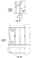
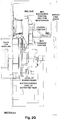
- the different modules of the Hermetic Press machine 100 are generally illustrated in Figs. 2A-G , including operator control station, Fig. 2C , electric cabinet, Fig. 2D , Doser Tap 825, Fig. 2E , for feeding the "wet” concrete, Hopper, Fig. 2F , for feeding the "dry” concrete and a cross-section illustration of the entire machine 100, Fig. 2G .
- this Hermetic Press machine is exemplary for means and methods for manufacturing cladding concrete blocks, but other similar or different machines may qualify and are contemplated within the scope of the present invention.
- machines with "linear" production methods namely without a revolving table and with an identical or similar production process, considering the final result, may also be used in the present invention for producing cladding blocks/elements and integrating anchors within them.
- the cladding block has a thickness between 25 mm and 35 mm, and is made of two concrete layers: one "top” layer with a thickness of about 10 mm, a second "bottom” layer with a thickness of 15 mm to 25 mm.
- the two-layer concrete comprises aggregates and sand in different sizes, type and level of content of cement, additives and water.
- colorants are added to the mixture that forms the concrete of the two layers to obtain a desired shade or hue.
- the anchors are fed into the Hermetic Press machine 100 such that they are eventually placed in exactly pre-selected locations at the cladding block.
- These anchors (which are fed in 90° bent position, see Figs. 3A-C ) are released onto the "dry” concrete layer and moved to the stage in the first, initial press, in which they are submerged into the "dry” layer. Then, in the following stage, the anchors are fixed within the "dry” layer by further pressing with the main press. At the end of pressing, the horizontal upper surface of the submerged anchor is levelled with the surface/height of the concrete.
- the following step is unloading the (pressed) element, which is carried out automatically in a regular manner by the Hermetic Press machine 100 .
- Machine 200 comprises a base 205 , a guiding beam or arm 215 and a carrying feeding device 210 that carries the anchors for introducing into the "dry" concrete layer after the Hermetic Press machine 100 completes a revolution of manufacturing a batch of two-layer, "wet" and “dry", concrete cladding blocks.
- Anchors are mounted on a tray, which is placed on base 205 of the complementing anchor embedding machine 200 , in a particular configuration and at 90° bent position.
- Such configuration on the trays is selected to match the desired number, location and/or distribution in the cladding blocks themselves. Every such tray is essentially designed with grooves at particular locations in the image of distribution of the anchors in the concrete block. This is so that when the anchors are released from device 210 they are placed in those locations, which are pre-selected to accommodate them in the concrete block.
- this method provides a wide range for organizing the anchors in the cladding elements according to particular construction requirements that take into account parameters such as material strength of the cladding blocks, stability over time and impact of humidity and temperature on expansion and contraction of the elements.
- Another advantage over a method of introducing anchors after preparation of the blocks is that the block integrated anchors do not adversely affect expansion and contraction of the concrete under thermal, pressure and/or humidity conditions. Anchors drilled into the concrete after preparing the blocks are more likely to cause local stresses and cracks, which may expand throughout the entire block with time.
- the method of feeding the anchors in the exact places in the elements, namely cladding blocks that the Hermetic Press machine 100 produces may be done by configuring the grooves in which the anchors are placed on the tray. Such configuration should match the intended configuration of the anchors when embedded in the concrete blocks as shaped by the plates 155 that hold them. Further, coordination of the operation between the two machines, 100 and 200 , and mounting and releasing mechanisms for arranging the anchors on the trays and dropping them exactly at their intended locations on the cladding blocks is also contemplated to ensure a supervised and regulated process.
- the anchor embedding machine 200 is automatic, semi-automatic or divided between manual labour and machine operation. In still another embodiment, this machine 200 comprises the following components:
- the machine head device travels along a defined track along the beam/arm between its base at the point of pick-up of the anchors with vacuum means to the drop-off point at the distal frame above the cladding block plates.
- This allows holding the anchors in releasable positions by the machine head device and dropping them off when reaching matched position of the anchors tray above a plate of a cladding block.
- the anchor embedding machine 200 may further comprise means for measuring and identifying the locations and positions of the anchors which are held by the machine head device 210 relative to the location, dimension and position of the cladding block plate. This provides accurate orientation of the anchors relative to the plate of the cladding block and ensures proper placement in the concrete according to a selected configuration.
- the machine 200 may also comprise means for driving the machine head device 210 to and holding it in accurate position above the plate of a cladding block. This ensures that the anchors are dropped off at exactly their intended pre-planned locations in the block to complete the process and eventually provide the desired stress-strain profile for the particular wall with the cladding elements.
- the anchors tray which holds the anchors before pick-up is made of a material selected from aluminium, metal or metallic materials, synthetic polymeric materials (polymer) and any combination thereof.
- the tray matches the dimensions of the plate of the machine for the elements produced, namely anchors integrated cladding blocks. To hold the anchors in place, such anchors tray comprises slots in which 90° bent anchors are threaded.
- threading the anchors is done manually before the manufacturing process initiates, so that a tray filled with bent anchors is provided to the machine when the cladding block is finished.
- the anchors are automatically stacked and fed in serial form and unloaded onto the cladding block according to computer generated and controlled plan.
- the anchors are automatically fed and placed on the trays in a particular selected configuration, which is computer generated and controlled. In these the machine beam or arm 200 and device 210 are maneuvered according to computer or controller commands for loading the anchors on the trays, traveling towards and above the concrete cladding block plates and unloading the anchors according to a selected location plan.
- the machine head device 210 travels the distance along the beam/arm 215 .
- the beam or arm 215 turns on its main axis and brings the device 210 to place above the plates 155 that contain the freshly produced cladding blocks.
- the machine head device 210 travels together with vacuum and compressed air system, where the vacuum system comprises vacuum mouthpieces for pulling the anchors off of the tray and arriving above plates 155 to fixed position. The anchors are caught by the mouthpieces with the vacuum mouthpieces.
- the empty tray is removed from the table and replaced with a filled tray or the emptied tray is filled again.
- different configurations of slots are made on the trays for embedding anchors in corresponding locations in the element.
- the different slots may be marked, for example with color, to distinguish between the different slot configurations on the trays. This ensures the matching of corresponding load and placement of the correct anchors that belong to a particular configuration, which is intended for a particular element together with double or more use of the same tray for multiple elements.
- the trays are provided in sufficient number, for example tens or hundreds of units, so that the rate of production in the machine is not compromised or slowed down due to slow load (of anchor units).
- the number of trays compensates the loading time of anchors on the trays and ensures an ongoing process of manufacturing the cladding blocks and embedding anchors in them to produce the anchor embedded cladding elements of the present invention.
- the production rate in the machine is between 15 and 30 seconds per cycle.
- the mechanism for holding, travelling and dropping off of the anchors by machine 200 is as described above.
- the machine head is equipped with vacuum system to pull the anchors off of the tray, hold, lower towards and push them onto the upper surface of the cladding block.
- the vacuum system comprises vacuum mouthpieces mounted on the machine 200 head, which are used to pull the anchors off upon application of vacuum, when arriving at the destination above the cladding blocks.
- the machine head moves backwards and the head is stabilized above the filled tray.
- a lower plate with the vacuum mouthpieces is pressed downwards with air pressure towards springs.
- the vacuum system is operated and the anchors are caught by the mouthpieces.
- the lower plate moves up by releasing air pressure and the action of the springs.
- the head travels on the beam towards the cladding block plates on machine 100 (in proper timing) and arrives above the concrete "lower", “dry” layer in the filled plate.
- the lower plate is pressed by air pressure, goes down on the anchors above the cladding block surface and pushes them in so that the vertical ends of the anchors are easily and smoothly partially stuck in the block concrete.
- the horizontal part 305 (see Figs. 3A-H and 5D-E ) is slightly embedded beneath the surface of the block so as not to protrude but still be accessible for lifting up.
- the vacuum is released leaving the anchors in the block.
- the air pressure is reversed and the lower plate goes up (the move is of several centimetres).
- the head travels back again for reload of anchors.
- the vacuum mouthpieces are located according to the desired final locations of the anchors in the cladding block. These locations can be modified according to the locations and number of anchors and their configuration on the anchors tray. Other parameters may be considered when determining the anchors configuration and corresponding configuration of vacuum mouthpieces such as the size and dimensions of the cladding block.
- Air pressure is generated by a compressed air system that uses springs or inflating and deflating air bags to push down and pull up the machine head over the lower plate.
- mechanical or magnetic means are used in the machine head device for lifting the anchors off of the tray and releasing them in the cladding blocks.
- magnet couplings or electromagnet in which alternating electrical current generates magnetic field, may be used to attract the anchors up from the tray, hold them while traveling along the beam/arm and release them into the cladding blocks at the distal end.
- Magnetized metal is used in the anchors for use of such magnetic means to hold and shift them from the tray to the cladding block.
- any press machine and the anchor feeding and embedding machine of the present invention requires accurate positioning and synchronizing between the machines to press the anchors in their proper place in the concrete claddings.
- the exemplary anchor feeding and embedding machine 100 is positioned in a particular position relative to the Hermetic Press Machine 200 and synchronized with the latter cycle of production to introduce the anchor carrying trays into a selected station at a particular time interval of this cycle.
- the relative positioning and configuration of these two machines should be so designed to manufacture uniform anchor embedded claddings. Accordingly, machine 100 should be leveled relative to machine 200 in particular distance, height and angle to allow secure delivery, positioning and locking of the anchors to the claddings.
- Adapting machine 100 to any production line of claddings is, therefore, unique to the particular characteristics of machine 100 and the particular features of the machine for manufacturing the claddings.
- the following exemplifies the coordinated operation of machine 200 and machine 100 and details how it is carried out:
- the coordinated and synchronized operation of the anchor feeding and embedding machine and cladding block manufacturing machine leads to embedding the anchors in the "dry" concrete layer by application of selected pressure to introduce one part of the anchor into the "dry” concrete layer and maintain another part of the anchors exposed on the surface of the "dry” layer and leveled with that surface.
- the means of the anchor feeding and embedding machine mainly its arm or beam are retreated out of the concrete cladding manufacturing machine before the latter moves its table that carries the cladding plates to the next station in the production line.
- Holding, carrying and releasing the anchors with vacuum means may be done in the following method:
- holding, carrying and releasing the anchors with magnetic or electromagnetic means may be done in the following method:
- the machine is guided by electricity and control system, and operates in coordination with the control system of the machine 100 for manufacturing the cladding blocks.
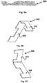
- FIG. 3A-H Exemplary non-limiting illustrations and dimensions of the anchors are shown in Figs. 3A-H .
- One typical structure of anchor 300 comprises two main parts, 305 and 310 , where the two parts are connected to each other with bendable axis 315 .
- parts 305 and 310 are oriented 90° one relative to the other by bending axis 315 between them. This way, the anchors are introduced into the cladding block in 90° position, which later enables using part 305 to connect with and hold to a support wall of a building.
- the shorter part 310 is embedded in the "dry" concrete block of the cladding block, and the longer part 305 is used to fasten to the support wall.
- Recesses 325 and 320 are used for nonuniform non-flat surface of the anchor, thereby increasing friction with the cement of the support wall and concrete of the cladding block, respectively, which enhances adherence and structural stability and strength.
- the surfaces of the anchors may be in any non-flat shape such as, wavy, serrated or roughened to increase such friction and structural strength.
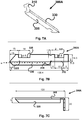
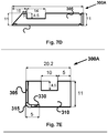
- Figs. 7A-E show another embodiment of the anchor 300 , namely 300A , with additional side blade, 330 , that connects in 90° relative to the longer part 305 of the anchor on the X-Y plane.
- side blade 330 is 90° relative to the shorter part 310 of the anchor in the Y-Z plane.
- the blade has inclined sharp edge at its distal end and a proximal side that is disconnected from the bending axis 315 and the short part of the anchor. The makes the blade connected only to the longer part 305 of the anchor.
- the blade 330 is introduced into the bulk of the cladding block together with the shorter part of the anchor 310 , thereby providing additional strength to fixing the anchor in place.
- the blade is pulled out of the cladding block when the longer part 305 of the anchor is straightened for fixing the block to a support wall.
- the blade is then inserted to the support wall together with the longer part, thus providing additional strength to holding the block.
- the blade's contribution is twofold. Its right angle relation with the shorter part 310 on the Y-Z plane increases the anchor's resistance to pulling out of the cladding block. Its right angle relation with the longer part 305 on the X-Y plane increases the anchor's hold to the support wall when the longer part is straightened and fixed to the wall. Further, the blade also improves the distribution of the load of the block on the support wall, thus decreasing the probability of detachment of the block off of the wall.
- Fig. 8 shows another embodiment of the anchor 300B with a hole 335 at the distal end of its long part.
- Hole 335 may be used to enhance the connection of the anchor 330B to a metal grid, which is overlaid on the support wall, by inserting a thread or wire through it and tying the thread or wire to the grid after pulling the long part of the anchor to vertical position.
- Such tying mechanically strengthens the attachment of the cladding block to the support wall in addition to cement or adhesive layer between the wall and block.
- the cladding block is fixed to the wall in at least two different modes of attachment, which ensures it remains permanently attached to the wall.
- the anchors are made of stainless steel according to regulations with thickness of between 0.6 an 1.0 mm, or customized according to demand.
- the width of the anchors is between 8 and 12 mm, however any other width may also be suitable.
- the length of the anchor vertical part which is stuck in the concrete is 20 mm, the length of the anchor horizontal part (designed to be covered by cast concrete of the wall) is 60 mm or any other dimension that fits the plan for the particular construction.
- the anchors comprise recesses to enable stronger adherence to the concrete in both sides, namely the element and wall.
- a dedicated device such as the one 400 illustrated in Figs. 5A-C is designed for this operation.
- Such a device comprises a "blade" element 410 with a tip 430 which is designed in shape, inner space and curvature, see Fig. 5B , to slide between the anchor 300 and cladding block 500 and apply sufficient force to lift the horizontal part 305 of the anchor 300 vertically.
- a holding handle 420 is attached to the distal end of the blade 410 and is particularly designed for convenient ergonomic holding.
- the worker pushes the edge of the "blade” 430 under the anchor and separates between the anchor and concrete (of the element).
- the "blade” which is composed of a stainless steel tube, sharpened at the edge, and with width that fits the anchor, slides under the part 305 of the anchor between this part and the surface of the block and with a simple action, a worker aligns the anchor (horizontal part) to vertical position.
- FIGs. 5D and 5E illustrate edges 310a and 310b of respective horizontal parts 300a and 300b of selected designs of the anchor.
- the edge may be flat, 310a , or inclined sharp, 310b .
- the device 400 is only at a single first contact point with the horizontal part 300b of the anchor. As a result, the device 400 does not have to be pushed under an edge front to lift the horizontal part, e.g., 310a , which makes it is easier for the worker to handle onsite.
- application is done in prefabricated factory for constructing a concrete wall with cladding elements in the following way:
- the cladding elements are attached to a support wall of a building onsite.
- the cladding elements are placed in a frame, which may be horizontal or inclined, where the front side of the cladding elements face the frame distal face and the anchors face up.
- a system e.g., an array, of rods holds the anchors, and the frame is lifted by a lever, of a crane for example, to the area of casting the wall.
- a second frame is located at the distal/opposite side beyond the reinforcement facing the interior of the construction. Casting fresh concrete between the two frames "submerges" the erect, vertically lifted part of the anchors in the fresh concrete.
- the anchors fix the cladding elements to the wall and generate a stress-strain characteristic that enables the wall to carry the load of the cladding elements under varying conditions.
- a third method for onsite attachment of the cladding elements to a construction wall with "wet" cement cover on an existing construction wall as follows:
- the weight of the cladding elements per one square meter is about 75 kg.
- the number of anchors per meter is between 20 and 40 per one square meter.
- the strength of pulling a single anchor is found to be between 140 and 250 kg. No tearing, rupture or breaking was found in strength tests done to the anchors. These strength levels are found sufficient according to planning and regulation demands with significantly large margins.
- Fig. 6 illustrates a system 600 with an external wall 620 covered with cladding elements 500 attached to the wall 620 with a plurality of anchors 300 .
- the anchors 300 end with sharp edge 310c to improve fastening the cladding elements 500 to the wall 620 .
- a thermal insulation mattress (or board) 610 is introduced that divides between the cladding elements 500 and wall 620 .
- Such mattress/board 610 fits to a precast concrete element or "in situ" casting.
- the anchors 500 can be longer, thicker and with a sharp edge, e.g., 310c , to allow an easy "Go Through” of the anchors into the mattress and be anchored to the concrete wall 610 when casting (the precast or "in situ” concrete).
Landscapes
- Engineering & Computer Science (AREA)
- Chemical & Material Sciences (AREA)
- Ceramic Engineering (AREA)
- Architecture (AREA)
- Manufacturing & Machinery (AREA)
- Mechanical Engineering (AREA)
- Civil Engineering (AREA)
- Structural Engineering (AREA)
- Physics & Mathematics (AREA)
- Electromagnetism (AREA)
- Press-Shaping Or Shaping Using Conveyers (AREA)
- Manufacturing Of Tubular Articles Or Embedded Moulded Articles (AREA)
- Devices For Post-Treatments, Processing, Supply, Discharge, And Other Processes (AREA)
Applications Claiming Priority (1)
| Application Number | Priority Date | Filing Date | Title |
|---|---|---|---|
| IL267153A IL267153B (en) | 2019-06-06 | 2019-06-06 | Concrete units to cover a structure with integrated anchors |
Publications (4)
| Publication Number | Publication Date |
|---|---|
| EP3748102A2 true EP3748102A2 (de) | 2020-12-09 |
| EP3748102A3 EP3748102A3 (de) | 2020-12-16 |
| EP3748102B1 EP3748102B1 (de) | 2025-10-22 |
| EP3748102C0 EP3748102C0 (de) | 2025-10-22 |
Family
ID=67734423
Family Applications (1)
| Application Number | Title | Priority Date | Filing Date |
|---|---|---|---|
| EP20275104.6A Active EP3748102B1 (de) | 2019-06-06 | 2020-06-08 | Betonbauelement mit integrierten ankern |
Country Status (3)
| Country | Link |
|---|---|
| US (1) | US20200385997A1 (de) |
| EP (1) | EP3748102B1 (de) |
| IL (1) | IL267153B (de) |
Families Citing this family (1)
| Publication number | Priority date | Publication date | Assignee | Title |
|---|---|---|---|---|
| IL267153B (en) | 2019-06-06 | 2020-05-31 | Ackerstein Ind Ltd | Concrete units to cover a structure with integrated anchors |
Citations (1)
| Publication number | Priority date | Publication date | Assignee | Title |
|---|---|---|---|---|
| IL267153A (en) | 2019-06-06 | 2019-07-31 | Ackerstein Ind Ltd | Concrete units for building cladding with integrated anchors |
Family Cites Families (4)
| Publication number | Priority date | Publication date | Assignee | Title |
|---|---|---|---|---|
| GB2222981B (en) * | 1988-09-22 | 1992-07-08 | Cyril Oury Duke | Manufacture of concrete products |
| US20070209308A1 (en) * | 2004-07-30 | 2007-09-13 | James Barrett | Faux-stone architectural panel system |
| DE102013100053A1 (de) * | 2013-01-04 | 2014-07-10 | Groz-Beckert Kg | Beton-Fertigteilelement mit Textilbewehrung und Haltern |
| FI20165851A7 (fi) * | 2016-11-14 | 2018-05-15 | Elematic Oyj | Menetelmä ja laitteisto esivalmistettujen betonituotteiden valamiseksi |
-
2019
- 2019-06-06 IL IL267153A patent/IL267153B/en active IP Right Grant
-
2020
- 2020-06-03 US US16/891,720 patent/US20200385997A1/en not_active Abandoned
- 2020-06-08 EP EP20275104.6A patent/EP3748102B1/de active Active
Patent Citations (1)
| Publication number | Priority date | Publication date | Assignee | Title |
|---|---|---|---|---|
| IL267153A (en) | 2019-06-06 | 2019-07-31 | Ackerstein Ind Ltd | Concrete units for building cladding with integrated anchors |
Also Published As
| Publication number | Publication date |
|---|---|
| US20200385997A1 (en) | 2020-12-10 |
| EP3748102B1 (de) | 2025-10-22 |
| IL267153A (en) | 2019-07-31 |
| EP3748102A3 (de) | 2020-12-16 |
| EP3748102C0 (de) | 2025-10-22 |
| IL267153B (en) | 2020-05-31 |
Similar Documents
| Publication | Publication Date | Title |
|---|---|---|
| EP2629948B1 (de) | Mobiles fertigungssystem für zementplatten | |
| EP3748102B1 (de) | Betonbauelement mit integrierten ankern | |
| KR20180036061A (ko) | 건식공법을 이용한 콘크리트 제품 제조장치 및 이를 이용한 콘크리트 제품 제조방법 | |
| US20220081916A1 (en) | Structure construction apparatus | |
| KR100552573B1 (ko) | 콘크리트 제품 자동 제조시스템및 그에 사용되어지는 충진유니트 | |
| US4738605A (en) | Installation for manufacturing reinforced concrete elements | |
| KR20150118767A (ko) | 적층양생식 pc구조물 생산장치 | |
| CN109822736B (zh) | 一种装配式墙板的生产工艺 | |
| CN105459247B (zh) | 一种砌块制造方法及砌块制造装置 | |
| US12371923B2 (en) | Wind tower printing device and method | |
| NO175772B (no) | Anordning til automatisk, vertikal stabling av gjenstander | |
| EP2529908A1 (de) | Positionierungsinstallation für verankerungen bei der vormontage von tafeln aus verstärktem zementmörtel | |
| AU2011360697B2 (en) | Method for the continuous production of composite formwork panel elements | |
| CN109227928A (zh) | 一种复合墙板生产线的筑模增强件自动布料设备 | |
| KR101553690B1 (ko) | 자동승강작동식 콘크리트구조물 생산장치 | |
| KR100666598B1 (ko) | 콘크리트 슬래브용 데크플레이트와 트러스거더 로딩시스템 | |
| CN218019244U (zh) | 一种能均匀布设浆料的布料器 | |
| EP2580036B1 (de) | System und verfahren zur herstellung von bodenfertigteilelementen aus beton | |
| US4261693A (en) | Partition block and method of manufacture | |
| CN109866341A (zh) | 加工墙体砌块设备 | |
| CN109809115A (zh) | 用于废料石膏板传输及定位的装置及相应的方法 | |
| CN211221287U (zh) | 适合双皮墙的斜向布料装置 | |
| RU2464392C1 (ru) | Способ возведения стен, установка для автоматизированного возведения стен из строительных модулей и комплект оборудования для механизированного возведения стен из строительных модулей | |
| CN111910754B (zh) | 一种混凝土预制构件及安装方法 | |
| CN113494173B (zh) | 找平机器人控制方法及找平机器人 |
Legal Events
| Date | Code | Title | Description |
|---|---|---|---|
| PUAI | Public reference made under article 153(3) epc to a published international application that has entered the european phase |
Free format text: ORIGINAL CODE: 0009012 |
|
| STAA | Information on the status of an ep patent application or granted ep patent |
Free format text: STATUS: THE APPLICATION HAS BEEN PUBLISHED |
|
| PUAL | Search report despatched |
Free format text: ORIGINAL CODE: 0009013 |
|
| AK | Designated contracting states |
Kind code of ref document: A2 Designated state(s): AL AT BE BG CH CY CZ DE DK EE ES FI FR GB GR HR HU IE IS IT LI LT LU LV MC MK MT NL NO PL PT RO RS SE SI SK SM TR |
|
| AX | Request for extension of the european patent |
Extension state: BA ME |
|
| AK | Designated contracting states |
Kind code of ref document: A3 Designated state(s): AL AT BE BG CH CY CZ DE DK EE ES FI FR GB GR HR HU IE IS IT LI LT LU LV MC MK MT NL NO PL PT RO RS SE SI SK SM TR |
|
| AX | Request for extension of the european patent |
Extension state: BA ME |
|
| RIC1 | Information provided on ipc code assigned before grant |
Ipc: E04F 13/14 20060101AFI20201109BHEP Ipc: E04F 13/08 20060101ALI20201109BHEP Ipc: B28B 5/04 20060101ALI20201109BHEP Ipc: E04B 1/41 20060101ALI20201109BHEP |
|
| STAA | Information on the status of an ep patent application or granted ep patent |
Free format text: STATUS: REQUEST FOR EXAMINATION WAS MADE |
|
| 17P | Request for examination filed |
Effective date: 20210616 |
|
| RBV | Designated contracting states (corrected) |
Designated state(s): AL AT BE BG CH CY CZ DE DK EE ES FI FR GB GR HR HU IE IS IT LI LT LU LV MC MK MT NL NO PL PT RO RS SE SI SK SM TR |
|
| STAA | Information on the status of an ep patent application or granted ep patent |
Free format text: STATUS: EXAMINATION IS IN PROGRESS |
|
| 17Q | First examination report despatched |
Effective date: 20221129 |
|
| GRAP | Despatch of communication of intention to grant a patent |
Free format text: ORIGINAL CODE: EPIDOSNIGR1 |
|
| STAA | Information on the status of an ep patent application or granted ep patent |
Free format text: STATUS: GRANT OF PATENT IS INTENDED |
|
| INTG | Intention to grant announced |
Effective date: 20250513 |
|
| GRAS | Grant fee paid |
Free format text: ORIGINAL CODE: EPIDOSNIGR3 |
|
| GRAA | (expected) grant |
Free format text: ORIGINAL CODE: 0009210 |
|
| STAA | Information on the status of an ep patent application or granted ep patent |
Free format text: STATUS: THE PATENT HAS BEEN GRANTED |
|
| AK | Designated contracting states |
Kind code of ref document: B1 Designated state(s): AL AT BE BG CH CY CZ DE DK EE ES FI FR GB GR HR HU IE IS IT LI LT LU LV MC MK MT NL NO PL PT RO RS SE SI SK SM TR |
|
| REG | Reference to a national code |
Ref country code: CH Ref legal event code: F10 Free format text: ST27 STATUS EVENT CODE: U-0-0-F10-F00 (AS PROVIDED BY THE NATIONAL OFFICE) Effective date: 20251022 Ref country code: GB Ref legal event code: FG4D |
|
| REG | Reference to a national code |
Ref country code: DE Ref legal event code: R096 Ref document number: 602020060771 Country of ref document: DE |
|
| REG | Reference to a national code |
Ref country code: IE Ref legal event code: FG4D |
|
| U01 | Request for unitary effect filed |
Effective date: 20251028 |
|
| U07 | Unitary effect registered |
Designated state(s): AT BE BG DE DK EE FI FR IT LT LU LV MT NL PT RO SE SI Effective date: 20251103 |