EP3747806A1 - Vorrichtung zum anpassen einer führungsbreite einer fördereinrichtung - Google Patents
Vorrichtung zum anpassen einer führungsbreite einer fördereinrichtung Download PDFInfo
- Publication number
- EP3747806A1 EP3747806A1 EP20175975.0A EP20175975A EP3747806A1 EP 3747806 A1 EP3747806 A1 EP 3747806A1 EP 20175975 A EP20175975 A EP 20175975A EP 3747806 A1 EP3747806 A1 EP 3747806A1
- Authority
- EP
- European Patent Office
- Prior art keywords
- guide
- adjusting
- adjusting element
- movement
- rotary
- Prior art date
- Legal status (The legal status is an assumption and is not a legal conclusion. Google has not performed a legal analysis and makes no representation as to the accuracy of the status listed.)
- Granted
Links
Images

Classifications
-
- B—PERFORMING OPERATIONS; TRANSPORTING
- B65—CONVEYING; PACKING; STORING; HANDLING THIN OR FILAMENTARY MATERIAL
- B65G—TRANSPORT OR STORAGE DEVICES, e.g. CONVEYORS FOR LOADING OR TIPPING, SHOP CONVEYOR SYSTEMS OR PNEUMATIC TUBE CONVEYORS
- B65G21/00—Supporting or protective framework or housings for endless load-carriers or traction elements of belt or chain conveyors
- B65G21/20—Means incorporated in, or attached to, framework or housings for guiding load-carriers, traction elements or loads supported on moving surfaces
- B65G21/2045—Mechanical means for guiding or retaining the load on the load-carrying surface
- B65G21/2063—Mechanical means for guiding or retaining the load on the load-carrying surface comprising elements not movable in the direction of load-transport
- B65G21/2072—Laterial guidance means
-
- B—PERFORMING OPERATIONS; TRANSPORTING
- B65—CONVEYING; PACKING; STORING; HANDLING THIN OR FILAMENTARY MATERIAL
- B65G—TRANSPORT OR STORAGE DEVICES, e.g. CONVEYORS FOR LOADING OR TIPPING, SHOP CONVEYOR SYSTEMS OR PNEUMATIC TUBE CONVEYORS
- B65G21/00—Supporting or protective framework or housings for endless load-carriers or traction elements of belt or chain conveyors
- B65G21/20—Means incorporated in, or attached to, framework or housings for guiding load-carriers, traction elements or loads supported on moving surfaces
- B65G21/2045—Mechanical means for guiding or retaining the load on the load-carrying surface
- B65G21/2063—Mechanical means for guiding or retaining the load on the load-carrying surface comprising elements not movable in the direction of load-transport
-
- B—PERFORMING OPERATIONS; TRANSPORTING
- B65—CONVEYING; PACKING; STORING; HANDLING THIN OR FILAMENTARY MATERIAL
- B65G—TRANSPORT OR STORAGE DEVICES, e.g. CONVEYORS FOR LOADING OR TIPPING, SHOP CONVEYOR SYSTEMS OR PNEUMATIC TUBE CONVEYORS
- B65G21/00—Supporting or protective framework or housings for endless load-carriers or traction elements of belt or chain conveyors
- B65G21/10—Supporting or protective framework or housings for endless load-carriers or traction elements of belt or chain conveyors movable, or having interchangeable or relatively movable parts; Devices for moving framework or parts thereof
- B65G21/14—Supporting or protective framework or housings for endless load-carriers or traction elements of belt or chain conveyors movable, or having interchangeable or relatively movable parts; Devices for moving framework or parts thereof to allow adjustment of length or configuration of load-carrier or traction element
-
- B—PERFORMING OPERATIONS; TRANSPORTING
- B65—CONVEYING; PACKING; STORING; HANDLING THIN OR FILAMENTARY MATERIAL
- B65G—TRANSPORT OR STORAGE DEVICES, e.g. CONVEYORS FOR LOADING OR TIPPING, SHOP CONVEYOR SYSTEMS OR PNEUMATIC TUBE CONVEYORS
- B65G47/00—Article or material-handling devices associated with conveyors; Methods employing such devices
- B65G47/22—Devices influencing the relative position or the attitude of articles during transit by conveyors
- B65G47/24—Devices influencing the relative position or the attitude of articles during transit by conveyors orientating the articles
-
- B—PERFORMING OPERATIONS; TRANSPORTING
- B67—OPENING, CLOSING OR CLEANING BOTTLES, JARS OR SIMILAR CONTAINERS; LIQUID HANDLING
- B67C—CLEANING, FILLING WITH LIQUIDS OR SEMILIQUIDS, OR EMPTYING, OF BOTTLES, JARS, CANS, CASKS, BARRELS, OR SIMILAR CONTAINERS, NOT OTHERWISE PROVIDED FOR; FUNNELS
- B67C3/00—Bottling liquids or semiliquids; Filling jars or cans with liquids or semiliquids using bottling or like apparatus; Filling casks or barrels with liquids or semiliquids
- B67C3/02—Bottling liquids or semiliquids; Filling jars or cans with liquids or semiliquids using bottling or like apparatus
- B67C3/22—Details
- B67C3/24—Devices for supporting or handling bottles
-
- B—PERFORMING OPERATIONS; TRANSPORTING
- B65—CONVEYING; PACKING; STORING; HANDLING THIN OR FILAMENTARY MATERIAL
- B65G—TRANSPORT OR STORAGE DEVICES, e.g. CONVEYORS FOR LOADING OR TIPPING, SHOP CONVEYOR SYSTEMS OR PNEUMATIC TUBE CONVEYORS
- B65G2201/00—Indexing codes relating to handling devices, e.g. conveyors, characterised by the type of product or load being conveyed or handled
- B65G2201/02—Articles
- B65G2201/0235—Containers
-
- B—PERFORMING OPERATIONS; TRANSPORTING
- B65—CONVEYING; PACKING; STORING; HANDLING THIN OR FILAMENTARY MATERIAL
- B65G—TRANSPORT OR STORAGE DEVICES, e.g. CONVEYORS FOR LOADING OR TIPPING, SHOP CONVEYOR SYSTEMS OR PNEUMATIC TUBE CONVEYORS
- B65G2207/00—Indexing codes relating to constructional details, configuration and additional features of a handling device, e.g. Conveyors
- B65G2207/08—Adjustable and/or adaptable to the article size
-
- B—PERFORMING OPERATIONS; TRANSPORTING
- B65—CONVEYING; PACKING; STORING; HANDLING THIN OR FILAMENTARY MATERIAL
- B65G—TRANSPORT OR STORAGE DEVICES, e.g. CONVEYORS FOR LOADING OR TIPPING, SHOP CONVEYOR SYSTEMS OR PNEUMATIC TUBE CONVEYORS
- B65G2812/00—Indexing codes relating to the kind or type of conveyors
- B65G2812/02—Belt or chain conveyors
- B65G2812/02267—Conveyors having endless traction elements
- B65G2812/02277—Common features for chain conveyors
- B65G2812/02326—Chains, cables or the like
Definitions
- the invention relates to a device for adapting a guide width of a conveying device for conveying containers for a container treatment system.
- Such guide or guide elements can for example be formed by rods, metal sheets or the like.
- the articles conveyed in each case can be in surface contact with the guide elements during their movement and are guided in their paths by the guide elements.
- the US 8,770,392 B2 relates to a width adjustment device for a conveyor corridor.
- the device has a rotatable control shaft in the form of an endless worm and a worm wheel.
- the shaft is a flexible shaft with a great length that is engaged with a tension retention system to absorb the tensile and compressive forces in the direction of rotation. The shaft is rotated to adjust the width of the conveyor corridor.
- the DE 10 2013 107 038 A1 discloses a transport section of a horizontal conveying device for conveying articles such as liquid containers or bottles, which are moved standing or hanging on a transport support extending in the horizontal conveying direction between two guide elements arranged approximately parallel at a distance corresponding at least to the article or container width. At least one of the two oppositely arranged guide elements can be adjusted in its distance to the other guide element transversely to the conveying direction by means of several adjusting elements anchored on a machine frame or frame.
- the adjusting elements are coupled to one another via a common rotary drive and are approximately synchronized, with each adjusting element transmitting a rotary drive of the common rotary drive via one or more transmission stages to a linear adjusting movement of the guide element suspended on it.
- Disadvantages of known solutions for adapting the guide widths may be a lack of flexibility, a high space requirement, high costs due to complex systems and / or a high level of clarification effort.
- the invention is based on the object of creating an alternative and / or improved device for adapting a guide width of a conveying device.
- the invention creates a device for adjusting a guide width of a conveyor for conveying containers for a container treatment system (e.g. for manufacturing, cleaning, testing, filling, closing, labeling, printing and / or packaging containers for liquid media, preferably beverages or liquid foods).
- the device has a longitudinally movable and flexible (e.g. flexible by elastic deformation) adjusting element.
- the device has a guide element, preferably a guide rail, for guiding the containers along a conveying direction.
- the guide element can expediently be movable (for example, displaceable) transversely to the conveying direction in order to adapt the guide width.
- the device has a transmission device, which is designed to adapt the guide width to convert a longitudinal movement, preferably a pushing and / or pulling movement, of the adjusting element into a movement (e.g. displacement) of the guide element transversely to the conveying direction.
- the flexibility of the adjusting element can also enable use in curved areas of the conveyor device.
- the adjustment element can be designed simply, since the adjustment of the conveying width is effected by means of a simple longitudinal movement of the adjustment element.
- This can be designed, for example, as a wire rope with which, for example, the requirement with regard to flexibility can also be met in a simple manner.
- the device can be mounted flexibly and only require little space. There may also be little clarification effort.
- the device can be easily retrofitted and implemented at low cost.
- the longitudinal movement of the adjusting element can expediently be parallel to the guide element and / or to the conveying direction.
- the adjusting element is a rope (e.g. formed from one or more parallel or twisted (laid) or braided wires and / or fibers), a belt, a wire, a fiber, a chain, a rod or a rod executed.
- the adjustment element can thus expediently be made inexpensive without impairing the reliability of the device.
- the adjusting element is elongated and / or extends along the guide element, preferably parallel to it. This makes it possible for the same adjusting element to be used for several devices arranged at a distance to adjust the guide width.
- the adjusting element is mounted so as to be longitudinally movable and / or non-rotatable by a motor and / or manually.
- the longitudinal movement for adjusting the adjusting element can thus be effected differently depending on the requirement.
- the transmission device is designed to convert the longitudinal movement of the adjusting element into a rotary movement and to convert the rotary movement into a linear movement for moving the guide element.
- the transmission device can expediently enable the guide width to be adjusted by only two movement transformations.
- the transmission device has a gear ratio not equal to 1, preferably less than 1.
- a particularly precise setting of the conveying width can be achieved if a large longitudinal movement of the adjusting element only leads to a small transverse movement of the guide element.
- the transmission device has a sliding element and a rotary element, which are in engagement with one another (for example, form-fit, force-fit and / or material-fit), for converting the longitudinal movement into the rotary movement.
- the sliding element and the rotating element can expediently have a gear ratio not equal to 1, preferably less than 1, in particular as a function of a diameter of the rotating element.
- the sliding element is attached to the adjusting element or integrated in the adjusting element.
- the attachment of the sliding element to the adjusting element can be selected appropriately if the adjusting element is, for example, a rope, a wire or a fiber.
- the sliding element therefore does not have to be present along the entire length of the adjusting element, but only in the relevant section.
- the integration of the sliding element in the adjusting element can in turn be expediently selected when the adjusting element is designed, for example, as a chain, belt, rod or rod. So the step of attachment can be saved.
- the sliding element is attached to the adjusting element by means of a clamping connection, and / or the sliding element is clamped directly to the adjusting element.
- the clamp connection offers an inexpensive, reliable and permanent connection between the sliding element and the adjusting element.
- the sliding element has a first clamping jaw and a second clamping jaw, between which a section of the adjusting element is clamped.
- a construction of the sliding element can be used advantageously, for example, when the adjusting element is a rope. The sliding element can thus easily be clamped onto the rope by grasping the rope.
- one of the first clamping jaw and the second clamping jaw is in engagement with the rotary element, preferably by means of a toothing (e.g. toothed rack section or toothed belt section).
- a toothing e.g. toothed rack section or toothed belt section.
- the transmission device has a guide.
- the sliding element and / or the adjusting element is guided longitudinally on the guide.
- the guide can prevent the sliding element and / or the adjusting element from rotating.
- the guide can bring about a defined longitudinal movement of the adjusting element so that the rotary element is driven as desired.
- the guide can be used in particular in an adjustment element in which there may be a risk of rotation, such as. B. with a rope.
- the sliding element is a (e.g., fixed or flexible) rod section, preferably a rack section, and / or the rotary element is a wheel, preferably a gear, particularly preferably a spur gear.
- a rack section can be attached to a rope, e.g. B. be clamped to drive a spur gear.
- the sliding element is a (for example, fixed or flexible) belt section, preferably a toothed belt section or a V-belt section, and / or the rotary element is a roller.
- the sliding element can be, for example, a chain section and / or the rotating element can be a chain wheel.
- the use of belts or chains can also allow an inexpensive and reliable implementation.
- the transmission device has a screw drive for converting the rotary movement into the linear movement.
- the use of the screw drive can enable partial integration in the rotary element.
- the screw drive has a (z. B. central) internal threaded hole of the rotary element.
- the screw drive can expediently have a gear ratio not equal to 1, preferably less than 1, in particular as a function of a diameter of the internally threaded hole and / or a pitch of the thread.
- the screw drive has a threaded rod which is expediently in engagement with the internally threaded hole, so that a rotary movement of the rotary element brings about a linear movement of the threaded rod.
- the guide element is attached to one end of the threaded rod.
- a connecting element which is non-rotatably connected to the threaded rod, and a further connecting element (e.g. a flat iron), which is firmly connected to the guide element, can preferably be connected to one another, particularly preferably screwed to one another.
- the guide element can thus be attached to one end of the threaded rod in a simple and reliable manner.
- the invention also relates to a device for transporting containers for a container treatment system (e.g. for manufacturing, cleaning, testing, filling, closing, labeling, printing and / or packaging containers for liquid media, preferably beverages or liquid food).
- the device has a conveying device with a conveying element, preferably a conveyor belt, for conveying the containers (e.g. standing or hanging).
- the device also has a plurality of devices for adjusting a guide width as disclosed herein, which are arranged along a longitudinal outer side or along both longitudinal outer sides of the conveying device, the devices arranged on the same longitudinal outer side each sharing the adjusting element.
- the multiple devices are preferably attached so that they cannot rotate and / or are height-adjustable.
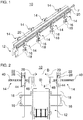
- the Figures 1 and 2 show a device 10 for transporting articles or containers (not shown), e.g. B. Bottles or cans.
- the device 10 can expediently be included in a container treatment system for the production, cleaning, testing, filling, closing, labeling, printing and / or packaging of containers, preferably for beverages or liquid food.
- the device 10 has a conveyor device 12 and several devices 14 for changing a guide width B (see Figure 2 ) for the conveyor 12.
- the conveying device 12 can have a transport support on which containers can be conveyed, for example standing.
- the conveyor 12 conveys the containers in a conveying direction F (see arrow in Figures 1 and 2 ).
- the conveyor device 12 can have a circulating conveyor belt (not shown) on which the containers can be conveyed.
- the guide width B of the conveying device 12 can be adjusted by means of the devices 14.
- the guide width B extends between mutually opposite guide elements 20 of the devices 14.
- a plurality of devices 14 are respectively arranged on both longitudinal outer sides of the conveyor device 12.
- the multiple devices 14 are expediently attached to the two longitudinal outer sides of the conveyor device 12.
- the devices 14 can be attached to the conveyor device 12 in such a way that they cannot rotate.
- the devices 14 are each fastened to one of the longitudinal outer sides of the conveyor device 12 by means of a holder 16.
- the holder 16 holds a rod-shaped or tubular body 18 in a rotationally fixed manner.
- the holders 16 expediently clamp the bodies 18. Before the clamping, the bodies 18 can be freely positioned with respect to the holders 16.
- the devices 14 are thus fastened to the conveyor device 12 in a height-adjustable manner.
- the bodies 18 are rotatably connected to the devices 14.
- the body 18 can be designed as a polygonal body, for. B. as a square body, as shown.
- the torsion-proof fastening can thus be implemented in a simple manner. It is also possible, for example, for the multiple devices 14 to be fastened in some other way, preferably secured against rotation, and / or to be arranged only on one of the two longitudinal outer sides of the conveyor device 12.
- FIGS. 3 and 4 show the devices 14 in greater detail.
- a housing 22 of the device 14 is open to illustrate a configuration.
- the device 14 has an adjusting element 24, a transmission device 26 and the guide element 20.
- the devices 14 on each one of the longitudinal outer sides of the conveying device 12 can jointly share a respective adjusting element 24 and at least partially share a respective guide element 20.
- the device 14 is designed to adjust the guide width B (see Figure 2 ) to transform a longitudinal movement of the adjusting element 24 into a transverse movement of the guide element 20 by means of the gear device 26.
- the device 14 can first convert the longitudinal movement of the adjusting element 24 into a rotary movement.
- the rotary movement in turn, can be converted into a linear movement for moving the guide element 20.
- the adjusting element 24 can be elongated, preferably rod-shaped or rod-shaped.
- the adjusting element 24 can extend along the conveyor 12, for. B. essentially in parallel.
- the adjusting element 24 is designed to be flexible, preferably as a flexible rope, e.g. B. a flexible wire rope as shown.
- the flexible rope can be formed for example from several parallel, twisted / twisted or braided wires or fibers.
- One advantage of using the flexible adjusting element 24 is that the device 14 can also be used along curves of the conveyor device 12. It is possible that instead of a flexible rope, for example, a flexible belt (e.g. endless belt), a single flexible wire, a single flexible fiber, a chain, a flexible rod, a flexible rod, etc. is used.
- a longitudinal movement of the adjusting element 24 can be effected by a motor or by hand.
- the longitudinal movement can be a pushing and / or pulling movement, depending on the configuration of the adjusting element 24.
- the longitudinal movement of the adjusting element 24 can, for example, by unilateral rolling, z. In the case of a rope, wire, fiber, belt or chain.
- a longitudinal displacement of the adjusting element 24 can, for example, also by a rotary drive, for. B. in the case of an endless belt or an endless chain, or by a linear drive, e.g. B. in the case of a rod or a rod.
- the adjusting element 24 is in engagement with the transmission device 26 via a sliding element 28.
- the sliding element 28 can be in engagement with a rotary element 30 of the transmission device 26.
- the engagement is such that a longitudinal movement of the sliding element 28 leads to a rotary movement of the rotary element 30.
- the sliding element 28 can be attached to the adjusting element 24.
- the sliding element 28 can be clamped onto the adjusting element 24.
- the sliding element 28 can have two clamping jaws which can clamp a section of the adjusting element 24 between them.
- Alternative or additional types of attachment are also possible, e.g. B. screw connection, adhesive connection, latching connection, etc.
- the sliding element 28 can be integrated in a section of the adjusting element 24.
- the adjusting element 24 can be designed as a toothed belt and the sliding element 28 as a toothed belt section of the toothed belt.
- the adjusting element 24 can be designed as a chain and the sliding element 28 to be designed as a chain section of the chain.
- the sliding element 28 can be designed as a rack section and the rotary element 30 as a gear, in particular a spur gear.
- the rack section meshes with the gear.
- a longitudinal movement / displacement movement of the rack section leads to a rotary movement of the gear wheel.
- the rack section can be formed by one of the clamping jaws of the sliding element 28.
- other pairings are used for the sliding element 28 and the rotary element 30 in order to convert a longitudinal movement of the sliding element 28 into a rotary movement of the rotary element 30.
- the sliding element 28 can be a chain section and the rotating element 30 can be a chain wheel.
- the sliding element 28 can also be a cable section, a belt section (for example a V-belt section or a toothed belt section), for example a profiled rod or rod section, and the rotary element 30 can be a driven roller.
- the device 14 can have the housing 22.
- the sliding element 28 and the rotating element 30 can be accommodated in the housing 22.
- the sliding element 28 can be mounted in the housing 22 so as to be longitudinally displaceable by a guide 34.
- the guide 34 can be formed, for example, by one or more housing walls of the housing 22.
- the guide 34 can furthermore be designed to prevent a rotation of the sliding element 28, ie a rotation of the sliding element 28 about its longitudinal axis, if desired.
- the rotary element 30 can be rotatably mounted in the housing 22.
- the rod-shaped or tubular body 18 can be non-rotatably connected to the housing 22, for. B. by a polygonal receptacle 32 in the housing 22.
- the housing 22 can for example have two housing halves that can be fastened to one another, as shown in the figures. In Figure 4 one of the two housing halves is omitted to illustrate an internal configuration of the device 14.
- the device 14 can also have a screw drive 36.
- a rotary movement of the rotary element 30 can be converted into a linear movement by means of the screw drive 36.
- the screw drive 36 has a central internally threaded hole 38 in the rotating element 30.
- the screw drive 36 also has a threaded rod 40.
- the threaded rod 40 is in engagement with the internally threaded hole 38.
- the guide member 20 is attached to one end of the threaded rod 40.
- the guide element 20 is preferably carried by the threaded rod 40.
- the threaded rod 40 is held non-rotatably on the guide element 20.
- a rotary movement of the rotary element 30 and thus of the internally threaded hole 38 thus leads to a linear movement of the threaded rod 40 transversely to the conveying direction F of the conveyor device 12.
- the linear movement of the threaded rod 40 leads to a transverse movement of the guide element 20 for setting the guide width B (see Fig Figure 2 ).
- a desired transmission ratio for the screw drive 36 and thus the transmission device 26 are predetermined.
- the translation can be influenced by a diameter of the rotary element 30.
- the transmission device 26 can be designed such that a comparatively large longitudinal movement of the adjusting element 24 leads to a comparatively small transverse movement of the threaded rod 40, for example in order to achieve a desired guide width B (see FIG Figure 2 ) to be able to adjust very precisely.
- the transmission device 26 can preferably have a transmission ratio of less than 1, ie an extent of the longitudinal movement of the adjusting element 24 is greater than an extent in the resulting linear movement of the threaded rod 40 or of the guide element 20.
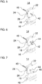
- connection element 42 e.g. B. be attached in the form of a bearing inner ring.
- An expedient two-part fastening element 44 can be firmly plugged, glued or the like onto the connecting element 42. The individual parts of the fastening element 44 can be screwed together, for example, as shown.
- the fastening element 44 can in turn have a fastening section 46, for. B. in the form of a threaded rod.
- a further connecting element 48 (see FIG Figure 2 ), e.g. B. a flat iron for connection to the guide element 20 are attached.
- the further connecting element 48 can, for example, be received in a receptacle of the guide element 20 (see also FIG Figure 2 ).
- the invention is not restricted to the preferred exemplary embodiments described above. Rather, a large number of variants and modifications are possible which also make use of the inventive concept and therefore fall within the scope of protection.
- the invention also claims protection for the subject matter and the features of the subclaims independently of the claims referred to.
- the individual features of independent claim 1 are disclosed independently of one another.
- the features of the subclaims are also disclosed independently of all the features of independent claim 1 and, for example, independently of the features relating to the presence and / or the configuration of the adjusting element, the guide element and / or the transmission device of independent claim 1.
Landscapes
- Engineering & Computer Science (AREA)
- Mechanical Engineering (AREA)
- Framework For Endless Conveyors (AREA)
Abstract
Description
- Die Erfindung betrifft eine Vorrichtung zum Anpassen einer Führungsbreite einer Fördereinrichtung zum Fördern von Behältern für eine Behälterbehandlungsanlage.
- Aus dem Stand der Technik sind bereits unterschiedliche Ausführungsvarianten von Vorrichtungen zum Transportieren von Behältern, wie Flaschen oder Dosen, in Behälterbehandlungsanlagen bekannt. Während der Beförderung werden die jeweiligen Behälter bewegt und hierbei entlang eines gewünschten Transportpfades gelenkt. Hierzu sind häufig ein oder mehrere Führungselemente vorhanden, die dem Transportpfad folgen und an denen die Behälter geführt werden.
- Derartige Führungs- oder Leitelemente können beispielsweise durch Stangen, Bleche o. dgl. ausgebildet sein. Die jeweils beförderten Artikel können während ihrer Bewegung in Oberflächenkontakt mit den Führungselementen stehen und werden durch die Führungselemente in ihren Bahnen gelenkt.
- Sollen Behälter mit einer ersten Geometrie und nachfolgend bzw. zu einem anderen Zeitpunkt Behälter mit einer davon abweichenden zweiten Geometrie die Transportvorrichtung passieren, so kann ein Anpassen der Position des oder der jeweiligen Führungselemente notwendig sein. Die Position der Führungselemente muss bei solchen Verstellvorgängen derart angepasst werden, dass der Abstand zwischen zwei Führungselementen beispielsweise etwas mehr als die Behälterbreite bzw. die Behälterhöhe beträgt, sodass die Behälter, ohne zu klemmen und ohne zu kippen, zwischen den jeweiligen Führungselementen geführt werden können.
- Die
US 8,770,392 B2 bezieht sich auf eine Breitenverstellvorrichtung für einen Förderkorridor. Die Vorrichtung weist eine drehbare Steuerwelle in Form einer Endlosschnecke und ein Schneckenrad auf. Die Welle ist eine biegsame Welle mit einer großen Länge, die mit einem Zughaltesystem in Eingriff steht, um die Zug- und Druckkräfte in Drehrichtung aufzunehmen. Zur Verstellung einer Breite des Förderkorridors wird die Welle rotiert. - Die
DE 10 2013 107 038 A1 offenbart einen Transportabschnitt einer Horizontalfördereinrichtung zur Beförderung von Artikeln wie Flüssigkeitsbehältern oder Flaschen, die stehend oder hängend auf einer sich in horizontaler Förderrichtung erstreckenden Transportauflage zwischen zwei ungefähr parallel in einem, mindestens der Artikel- oder Behälterbreite entsprechenden Abstand angeordneten Führungselementen bewegt werden. Zumindest eines der beiden gegenüberliegend angeordneten Führungselemente ist über mehrere, an einem Maschinenrahmen oder Gestell verankerte Verstellelemente quer zur Förderrichtung in seinem Abstand zum anderen Führungselement verstellbar. Die Verstellelemente sind über einen gemeinsamen Drehantrieb miteinander gekoppelt und annähernd synchronisiert, wobei jedes Verstellelement einen rotatorischen Antrieb des gemeinsamen Drehantriebs über eine oder mehrere Übersetzungsstufen auf eine lineare Stellbewegung des daran aufgehängten Führungselements überträgt. - Nachteilig an bekannten Lösungen zur Führungsbreitenanpassung können eine mangelnde Flexibilität, ein hoher Platzbedarf, hohe Kosten aufgrund komplexer Systeme und/oder ein hoher Klärungsaufwand sein.
- Der Erfindung liegt die Aufgabe zu Grunde, eine alternative und/oder verbesserte Vorrichtung zum Anpassen einer Führungsbreite einer Fördereinrichtung zu schaffen.
- Die Aufgabe wird gelöst durch die Merkmale des unabhängigen Anspruchs 1. Vorteilhafte Weiterbildungen sind in den abhängigen Ansprüchen und der Beschreibung angegeben.
- Die Erfindung schafft eine Vorrichtung zum Anpassen einer Führungsbreite einer Fördereinrichtung zum Fördern von Behältern für eine Behälterbehandlungsanlage (z. B. zum Herstellen, Reinigen, Prüfen, Abfüllen, Verschließen, Etikettieren, Bedrucken und/oder Verpacken von Behältern für flüssige Medien, vorzugsweise Getränke oder flüssige Nahrungsmittel). Die Vorrichtung weist ein längsbewegliches und biegsames (z. B. durch elastisches Verformen biegsames) Verstellelement auf. Die Vorrichtung weist ein Führungselement, vorzugsweise ein Führungsgeländer, zum Führen der Behälter entlang einer Förderrichtung auf. Das Führungselement kann zweckmäßig zum Anpassen der Führungsbreite quer zu der Förderrichtung bewegbar (z. B. verschiebbar) sein. Die Vorrichtung weist eine Getriebeeinrichtung auf, die zum Anpassen der Führungsbreite dazu ausgebildet ist, eine Längsbewegung, vorzugsweise eine Schub- und/oder Zugbewegung, des Verstellelements zu einer Bewegung (z. B. Verschiebung) des Führungselements quer zu der Förderrichtung umzuformen.
- Die Biegsamkeit des Verstellelements kann eine Anwendung auch in Kurvenbereichen der Fördereinrichtung ermöglichen. Das Verstellelement kann einfach ausgestaltet sein, da die Einstellung der Förderbreite mittels einer einfachen Längsbewegung des Verstellelements bewirkt wird. Dieses kann beispielsweise als ein Drahtseil ausgeführt sein, mit dem sich beispielsweise auf einfache Weise auch die Anforderung bezüglich der Biegsamkeit erfüllen lässt. Somit braucht kein kompliziertes und teures Verstellelement, wie beispielsweise eine drehbare Welle oder Ähnliches, verwendet werden. Die Vorrichtung kann flexibel montiert werden und einen nur geringen Platzbedarf aufweisen. Es kann ferner ein geringer Klärungsaufwand bestehen. Die Vorrichtung kann leicht nachrüstbar sein und kostengünstig implementiert werden.
- Zweckmäßig kann die Längsbewegung des Verstellelements parallel zum Führungselement und/oder zur Förderrichtung sein.
- In einem Ausführungsbeispiel ist das Verstellelement als ein Seil (z. B. gebildet aus einem oder mehreren parallelen oder verdrehten (geschlagenen) oder geflochtenen Drähten und oder Fasern), ein Riemen, ein Draht, eine Faser, eine Kette, ein Stab oder eine Stange ausgeführt. Zweckmäßig kann das Verstellelement somit kostengünstig ausgeführt sein, ohne dass eine Zuverlässigkeit der Vorrichtung beeinträchtigt wird.
- In einem weiteren Ausführungsbeispiel ist das Verstellelement länglich ausgebildet und/oder erstreckt sich entlang des Führungselements, vorzugsweise parallel dazu. Damit kann ermöglich werden, dass dasselbe Verstellelement für mehrere beabstandet angeordnete Vorrichtungen zum Anpassen der Führungsbreite verwendet werden kann.
- In einem weiteren Ausführungsbeispiel ist das Verstellelement motorisch und/oder manuell längsbewegbar und/oder nicht drehbar gelagert. Die Längsbewegung zum Verstellen des Verstellelements kann somit je nach Anforderung unterschiedlich bewirkt werden.
- In einer Ausführungsform ist die Getriebeeinrichtung dazu ausgebildet, die Längsbewegung des Verstellelements in eine Drehbewegung umzuformen und die Drehbewegung in eine Linearbewegung zur Bewegung des Führungselements umzuformen. Zweckmäßig kann die Getriebeeinrichtung so durch nur zwei Bewegungsumformungen eine Verstellung der Führungsbreite ermöglichen.
- In einer weiteren Ausführungsform weist die Getriebeeinrichtung eine Übersetzung ungleich 1, vorzugsweise kleiner als 1, auf. So kann beispielsweise eine besonders genaue Einstellung der Förderbreite erreicht werden, wenn eine große Längsbewegung des Verstellelements lediglich zu einer kleinen Querbewegung des Führungselements führt.
- In einer Ausführungsvariante weist die Getriebeeinrichtung ein Schiebeelement und ein Drehelement, die miteinander in (z. B. formschlüssigem, kraftschlüssigem und/oder stoffschlüssigem) Eingriff sind, zum Umformen der Längsbewegung in die Drehbewegung auf.
- Zweckmäßig können das Schiebeelement und das Drehelement eine Übersetzung ungleich 1, vorzugsweise kleiner als 1, aufweisen, insbesondere in Abhängigkeit von einem Durchmesser des Drehelements.
- In einer Weiterbildung ist das Schiebeelement an dem Verstellelement angebracht oder in dem Verstellelement integriert. Die Anbringung des Schiebeelements an dem Verstellelement kann zweckmäßig gewählt werden, wenn das Verstellelement beispielsweise ein Seil, ein Draht oder eine Faser ist. Das Schiebeelement muss somit nicht entlang der gesamten Länge des Verstellelements vorhanden sein, sondern nur im relevanten Abschnitt. Die Integration des Schiebeelements in dem Verstellelement kann wiederum zweckmäßig dann gewählt werden, wenn das Verstellelement beispielsweise als Kette, Riemen, Stab oder Stange ausgeführt ist. So kann der Schritt der Anbringung eingespart werden.
- In einer weiteren Ausführungsvariante ist das Schiebeelement mittels einer Klemmverbindung an dem Verstellelement angebracht, und/oder das Schiebeelement ist direkt an dem Verstellelement angeklemmt. Die Klemmverbindung bietet eine kostengünstige, zuverlässige und dauerhafte Verbindung zwischen dem Schiebeelement und dem Verstellelement.
- In einem Ausführungsbeispiel weist das Schiebeelement eine erste Klemmbacke und eine zweite Klemmbacke auf, zwischen denen ein Abschnitt des Verstellelements eingeklemmt ist. Ein solcher Aufbau des Schiebeelements kann beispielsweise vorteilhaft verwendet werden, wenn das Verstellelement ein Seil ist. Das Schiebeelement kann so einfach an das Seil angeklemmt werden, indem es das Seil umgreift.
- In einer Weiterbildung ist eine von der ersten Klemmbacke und der zweiten Klemmbacke in Eingriff mit dem Drehelement, vorzugsweise mittels einer Verzahnung (z. B. Zahnstangenabschnitt oder Zahnriemenabschnitt). Dies ermöglicht eine Funktionsintegration, da die Klemmbacke sowohl zum Anbringen an dem Verstellelement als auch zum Antreiben des Drehelements verwendbar ist.
- In einem weiteren Ausführungsbeispiel weist die Getriebeeinrichtung eine Führung auf. Das Schiebeelement und/oder das Verstellelement ist an der Führung längsgeführt. Alternativ oder zusätzlich kann die Führung eine Verdrehung des Schiebeelements und/oder des Verstellelements verhindern. Die Führung kann eine definierte Längsbewegung des Verstellelements bewirken, sodass das Drehelement wie gewünscht angetrieben wird. Die Führung kann insbesondere bei einem Verstellelement verwendet werden, bei dem ein Risiko hinsichtlich einer Verdrehung bestehen kann, wie z. B. bei einem Seil.
- In einer Ausführungsform ist das Schiebeelement ein (z. B. fester oder biegsamer) Stangenabschnitt, vorzugsweise ein Zahnstangenabschnitt, und/oder das Drehelement ist ein Rad, vorzugsweise ein Zahnrad, besonders bevorzugt ein Stirnzahnrad. Besonders bevorzugt kann so beispielsweise ein Zahnstangenabschnitt an einem Seil angebracht, z. B. angeklemmt sein, um ein Stirnzahnrad anzutreiben.
- In einer weiteren Ausführungsform ist das Schiebeelement ein (z. B. fester oder biegsamer) Riemenabschnitt, vorzugsweise ein Zahnriemenabschnitt oder ein Keilriemenabschnitt, und/oder das Drehelement ist eine Rolle. Alternativ kann das Schiebeelement beispielsweise ein Kettenabschnitt und/oder das Drehelement ein Kettenrad sein. Die Verwendung von Riemen oder Ketten kann ebenfalls eine kostengünstige und zuverlässige Implementierung ermöglichen.
- In einer Ausführungsvariante weist die Getriebeeinrichtung einen Gewindetrieb zum Umformen der Drehbewegung in die Linearbewegung auf. Die Verwendung des Gewindetriebs kann eine teilweise Integration in dem Drehelement ermöglichen.
- In einer Weiterbildung weist der Gewindetrieb ein (z. B. zentrales) Innengewindeloch des Drehelements auf. Dadurch kann beispielsweise Bauraum eingespart werden.
- Zweckmäßig kann der Gewindetrieb eine Übersetzung ungleich 1, vorzugsweise kleiner als 1, aufweisen, insbesondere in Abhängigkeit von einem Durchmesser des Innengewindelochs und/oder einer Steigung des Gewindes.
- In einer weiteren Ausführungsvariante weist der Gewindetrieb eine Gewindestange auf, die zweckmäßig in Eingriff mit dem Innengewindeloch ist, sodass eine Drehbewegung des Drehelements eine Linearbewegung der Gewindestange bewirkt.
- In einem Ausführungsbeispiel ist das Führungselement an einem Ende der Gewindestange angebracht. Vorzugsweise kann ein Verbindungselement, das drehfest mit der Gewindestange verbunden ist, und ein weiteres Verbindungselement (z. B. ein Flacheisen), das fest mit dem Führungselement verbunden ist, miteinander verbunden, besonders bevorzugt miteinander verschraubt, sein. So kann das Führungselement auf einfache und zuverlässige Weise an einem Ende der Gewindestange angebracht werden.
- Die Erfindung betrifft auch eine Vorrichtung zum Transportieren von Behältern für eine Behälterbehandlungsanlage (z. B. zum Herstellen, Reinigen, Prüfen, Abfüllen, Verschließen, Etikettieren, Bedrucken und/oder Verpacken von Behältern für flüssige Medien, vorzugsweise Getränke oder flüssige Nahrungsmittel). Die Vorrichtung weist eine Fördereinrichtung mit einem Förderelement, vorzugsweise einem Förderband, zum Fördern der Behälter (z. B. stehend oder hängend) auf. Die Vorrichtung weist ferner mehrere Vorrichtungen zum Anpassen einer Führungsbreite wie hierin offenbart auf, die entlang einer Längsaußenseite oder entlang beider Längsaußenseiten der Fördereinrichtung angeordnet sind, wobei die auf derselben Längsaußenseite angeordneten Vorrichtungen jeweils das Verstellelement teilen. Vorzugsweise sind die mehreren Vorrichtungen verdrehsicher und/oder höhenverstellbar angebracht.
- Die zuvor beschriebenen bevorzugten Ausführungsformen und Merkmale der Erfindung sind beliebig miteinander kombinierbar.
- Weitere Einzelheiten und Vorteile der Erfindung werden im Folgenden unter Bezug auf die beigefügten Zeichnungen beschrieben. Es zeigen:
- Figur 1
- eine perspektivische Ansicht einer Vorrichtung zum Transportieren von Behältern gemäß einem Ausführungsbeispiel der vorliegenden Offenbarung;
- Figur 2
- eine Vorderansicht der beispielhaften Vorrichtung zum Transportieren von Behältern;
- Figur 3
- eine perspektivische Ansicht einer Vorrichtung zum Verändern einer Führungsbreite einer Fördereinrichtung zum Fördern von Behältern gemäß einem Ausführungsbeispiel der vorliegenden Offenbarung;
- Figur 4
- eine perspektivische Ansicht der beispielhaften Vorrichtung zum Verändern der Führungsbreite, mit teilweise geöffnetem Gehäuse; und
- Figuren 5 -7
- perspektivische Ansichten der beispielhaften Vorrichtung zum Verändern der Führungsbreite, die einen Aufbau eines Verbindungsbauteils zur Anbringung an ein Führungselement der Vorrichtung zum Verändern der Führungsbreite zeigen.
- Die in den Figuren gezeigten Ausführungsformen stimmen zumindest teilweise überein, sodass ähnliche oder identische Teile mit den gleichen Bezugszeichen versehen sind und zu deren Erläuterung auch auf die Beschreibung der anderen Ausführungsformen bzw. Figuren verwiesen wird, um Wiederholungen zu vermeiden.
- Die
Figuren 1 und 2 zeigen eine Vorrichtung 10 zum Transportieren von Artikeln oder Behältern (nicht dargestellt), z. B. Flaschen oder Dosen. Die Vorrichtung 10 kann zweckmäßig in einer Behälterbehandlungsanlage zum Herstellen, Reinigen, Prüfen, Füllen, Verschließen, Etikettieren, Bedrucken und/oder Verpacken von Behältern, vorzugsweise für Getränke oder flüssige Nahrungsmittel, umfasst sein. - Die Vorrichtung 10 weist eine Fördereinrichtung 12 und mehrere Vorrichtungen 14 zum Verändern einer Führungsbreite B (siehe
Figur 2 ) für die Fördereinrichtung 12 auf. - Die Fördereinrichtung 12 kann eine Transportauflage aufweisen, auf der Behälter beispielsweise stehend gefördert werden können. Die Fördereinrichtung 12 fördert die Behälter in einer Förderrichtung F (siehe Pfeil in
Figur 1 und 2 ). Beispielsweise kann die Fördereinrichtung 12 ein umlaufendes Förderband (nicht dargestellt) aufweisen, auf dem die Behälter gefördert werden können. Um unterschiedlich große Behälter mit der gleichen Fördereinrichtung 12, insbesondere einspurig und/oder mit verringertem Kipprisiko, fördern zu können, kann die Führungsbreite B der Fördereinrichtung 12 mittels der Vorrichtungen 14 verstellt werden. Die Führungsbreite B erstreckt sich zwischen einander gegenüberliegenden Führungselementen 20 der Vorrichtungen 14. - Jeweils mehrere Vorrichtungen 14 sind an beiden Längsaußenseiten der Fördereinrichtung 12 angeordnet. Zweckmäßig sind die mehreren Vorrichtungen 14 an den beiden Längsaußenseiten der Fördereinrichtung 12 befestigt. Die Vorrichtungen 14 können so an der Fördereinrichtung 12 befestigt sein, dass sie sich nicht verdrehen können. Beispielsweise sind die Vorrichtungen 14 jeweils mittels einer Halterung 16 an einer der Längsaußenseiten der Fördereinrichtung 12 befestigt. Die Halterung 16 hält jeweils einen stab- oder rohrförmigen Körper 18 drehfest. Zweckmäßig klemmen die Halterungen 16 die Körper 18. Vor dem Klemmen können die Körper 18 frei bezüglich der Halterungen 16 positioniert werden. Die Vorrichtungen 14 sind somit höhenverstellbar an der Fördereinrichtung 12 befestigt. Die Körper 18 sind drehfest mit den Vorrichtungen 14 verbunden. Zweckmäßig können die Körper 18 als mehrkantige Körper ausgeführt sein, z. B. als Vierkant-Körper, wie dargestellt ist. Somit kann die verdrehsichere Befestigung auf einfache Weise realisiert werden. Es ist beispielsweise auch möglich, dass die mehreren Vorrichtungen 14 anderweitig, vorzugsweise verdrehsicher, befestigt sind und/oder nur an einer der beiden Längsaußenseiten der Fördereinrichtung 12 angeordnet sind.
- Die
Figuren 3 und 4 zeigen die Vorrichtungen 14 in größerem Detail. InFigur 4 ist zur Veranschaulichung einer Konfiguration ein Gehäuse 22 der Vorrichtung 14 geöffnet. - Die Vorrichtung 14 weist ein Verstellelement 24, eine Getriebeeinrichtung 26 und das Führungselement 20 auf. Die Vorrichtungen 14 auf jeweils einer der Längsaußenseiten der Fördereinrichtung 12 können sich gemeinsam ein jeweiliges Verstellelement 24 und zumindest teilweise ein jeweiliges Führungselement 20 teilen.
- Die Vorrichtung 14 ist dazu ausgebildet, zum Verstellen der Führungsbreite B (siehe
Figur 2 ) eine Längsbewegung des Verstellelements 24 mittels der Getriebeeinrichtung 26 zu einer Querbewegung des Führungselements 20 umzuformen. - Im Einzelnen kann die Vorrichtung 14 die Längsbewegung des Verstellelements 24 zunächst in eine Drehbewegung umformen. Die Drehbewegung wiederum kann in eine Linearbewegung zum Verschieben des Führungselements 20 umgeformt werden.
- Das Verstellelement 24 kann länglich, vorzugsweise stab- oder stangenförmig, ausgeführt sein. Das Verstellelement 24 kann sich entlang der Fördereinrichtung 12 erstrecken, z. B. im Wesentlichen parallel dazu. Das Verstellelement 24 ist biegsam ausgeführt, vorzugsweise als ein biegsames Seil, z. B. ein biegsames Drahtseil, wie dargestellt ist. Das biegsame Seil kann beispielsweise aus mehreren parallelen, verdrehten/geschlagenen oder geflochtenen Drähten oder Fasern gebildet sein. Ein Vorteil bei der Verwendung des biegsamen Verstellelements 24 liegt darin, dass die Vorrichtung 14 auch entlang von Kurven der Fördereinrichtung 12 verwendet werden kann. Es ist möglich, dass statt eines biegsamen Seils beispielsweise ein biegsamer Riemen (z. B. Endlosriemen), ein einziger biegsamer Draht, eine einzige biegsame Faser, eine Kette, ein biegsamer Stab, eine biegsame Stange usw. verwendet wird.
- Eine Längsbewegung des Verstellelements 24 kann motorisch oder händisch bewirkt werden. Die Längsbewegung kann je nach Ausgestaltung des Verstellelements 24 eine Schubund/oder Zugbewegung sein. Die Längsbewegung des Verstellelements 24 kann beispielsweise durch einseitiges Aufrollen, z. B. im Falle eines Seils, eines Drahts, einer Faser, eines Riemens oder einer Kette, erfolgen. Eine Längsverschiebung des Verstellelements 24 kann beispielsweise ebenfalls durch einen Umlaufantrieb, z. B. im Falle eines Endlosriemens oder einer Endloskette, oder durch einen Linearantrieb, z. B. im Falle eines Stabs oder einer Stange, erfolgen.
- Das Verstellelement 24 ist über ein Schiebeelement 28 in Eingriff mit der Getriebeeinrichtung 26. Im Einzelnen kann das Schiebeelement 28 in Eingriff mit einem Drehelement 30 der Getriebeeinrichtung 26 sein. Der Eingriff ist derart, dass eine Längsbewegung des Schiebeelements 28 zu einer Drehbewegung des Drehelements 30 führt.
- Wie dargestellt ist, kann das Schiebeelement 28 an dem Verstellelement 24 angebracht sein. Beispielsweise kann das Schiebeelement 28 an dem Verstellelement 24 angeklemmt sein. Das Schiebeelement 28 kann zwei Klemmbacken aufweisen, die einen Abschnitt des Verstellelements 24 zwischen sich einklemmen können. Alternative oder zusätzliche Anbringungsarten sind auch möglich, z. B. Schraubverbindung, Klebeverbindung, Rastverbindung usw. Es ist auch möglich, dass das Schiebeelement 28 in einem Abschnitt des Verstellelements 24 integriert ist. Z. B. kann das Verstellelement 24 als ein Zahnriemen und das Schiebeelement 28 als ein Zahnriemenabschnitt des Zahnriemens ausgeführt sein. Es ist beispielsweise auch möglich, dass das Verstellelement 24 als eine Kette und das Schiebeelement 28 als ein Kettenabschnitt der Kette ausgeführt ist.
- Wie außerdem dargestellt ist, kann das Schiebelement 28 als ein Zahnstangenabschnitt und das Drehelement 30 als ein Zahnrad, insbesondere ein Stirnzahnrad, ausgeführt sein. Der Zahnstangenabschnitt kämmt mit dem Zahnrad. Eine Längsbewegung/Verschiebebewegung des Zahnstangenabschnitts führt zu einer Drehbewegung des Zahnrads. Beispielsweise kann der Zahnstangenabschnitt durch eine der Klemmbacken des Schiebeelements 28 gebildet sein. Es ist auch möglich, dass andere Paarungen für das Schiebeelement 28 und das Drehelement 30 verwendet werden, um eine Längsbewegung des Schiebeelements 28 in eine Drehbewegung des Drehelements 30 umzuformen. Beispielsweise kann das Schiebeelement 28 ein Kettenabschnitt und das Drehelement 30 ein Kettenrad sein. Das Schiebeelement 28 kann auch ein Seilabschnitt, ein Riemenabschnitt (z. B. Keilriemenabschnitt oder ein Zahnriemenabschnitt), ein beispielsweise profilierter Stab- oder Stangenabschnitt sein, und das Drehelement 30 kann eine angetriebene Rolle sein.
- Die Vorrichtung 14 kann das Gehäuse 22 aufweisen. In dem Gehäuse 22 können das Schiebeelement 28 und das Drehelement 30 aufgenommen sein. Das Schiebeelement 28 kann durch eine Führung 34 längsverschiebbar in dem Gehäuse 22 gelagert sein. Die Führung 34 kann beispielsweise durch eine oder mehrere Gehäusewände des Gehäuses 22 ausgebildet sein. Die Führung 34 kann ferner dazu ausgebildet sein, ein Verdrehen des Schiebeelements 28, d. h. eine Drehung des Schiebeelements 28 um dessen Längsachse, zu verhindern, wenn gewünscht. Das Drehelement 30 kann drehbar in dem Gehäuse 22 gelagert sein. An einem unteren Ende des Gehäuses 22 kann der stab- oder rohrförmige Körper 18 drehfest mit dem Gehäuse 22 verbunden sein, z. B. durch eine mehrkantige Aufnahme 32 im Gehäuse 22. Das Gehäuse 22 kann beispielsweise zwei aneinander befestigbare Gehäusehälften aufweisen, wie in den Figuren dargestellt ist. In
Figur 4 ist zum Darstellen einer Innenkonfiguration der Vorrichtung 14 eine der beiden Gehäusehälften weggelassen. - Die Vorrichtung 14 kann ferner einen Gewindetrieb 36 aufweisen. Mittels des Gewindetriebs 36 kann eine Drehbewegung des Drehelements 30 in eine Linearbewegung umgeformt werden. Der Gewindetrieb 36 weist ein zentrales Innengewindeloch 38 in dem Drehelement 30 auf. Der Gewindetrieb 36 weist zudem eine Gewindestange 40 auf. Die Gewindestange 40 ist in Eingriff mit dem Innengewindeloch 38. Das Führungselement 20 ist an einem Ende der Gewindestange 40 angebracht. Das Führungselement 20 ist vorzugsweise von der Gewindestange 40 getragen. Die Gewindestange 40 ist drehfest an dem Führungselement 20 gehalten. Eine Drehbewegung des Drehelements 30 und somit des Innengewindelochs 38 führt somit zu einer Linearbewegung der Gewindestange 40 quer zu der Förderrichtung F der Fördereinrichtung 12. Die Linearbewegung der Gewindestange 40 führt zu einer Querbewegung des Führungselements 20 zum Einstellen der Führungsbreite B (siehe
Figur 2 ). - Durch eine Anpassung der Steigung der Gewindegänge und eines Durchmessers des Innengewindelochs 38 und der Gewindestange 40 kann ein gewünschtes Übersetzungsverhältnis für den Gewindetrieb 36 und damit die Getriebeeinrichtung 26 vorbestimmt werden. Ferner kann die Übersetzung durch einen Durchmesser des Drehelements 30 beeinflusst werden. Beispielsweise kann die Getriebeeinrichtung 26 so ausgeführt sein, dass eine vergleichsweise große Längsbewegung des Verstellelements 24 zu einer vergleichsweise kleinen Querbewegung der Gewindestange 40 führt, um beispielsweise eine gewünschte Führungsbreite B (siehe
Figur 2 ) sehr genau einstellen zu können. Vorzugsweise kann die Getriebeeinrichtung 26 eine Übersetzung kleiner als 1 aufweisen, d. h., ein Ausmaß der Längsbewegung des Verstellelements 24 ist größer als ein Ausmaß in der resultierenden Linearbewegung der Gewindestange 40 bzw. des Führungselements 20. - Die
Figuren 5 bis 7 zeigen einen beispielhaften Aufbau einer Verbindung der Gewindestange 40 und des Führungselements 20. An einem dem Führungselement 20 zugewandten Ende kann auf der Gewindestange 40 ein Verbindungselement 42, z. B. in Form eines Lagerinnenrings, befestigt sein. Auf das Verbindungselement 42 kann ein zweckmäßig zweiteiliges Befestigungselement 44 fest aufgesteckt, verklebt oder Ähnliches sein. Die Einzelteile des Befestigungselements 44 können beispielsweise miteinander verschraubt sein, wie dargestellt ist. Das Befestigungselement 44 kann wiederum einen Befestigungsabschnitt 46, z. B. in Form einer Gewindestange, aufweisen. An dem Befestigungsabschnitt 46 kann ein weiteres Verbindungselement 48 (sieheFigur 2 ), z. B. ein Flacheisen, zur Verbindung mit dem Führungselement 20 befestigt werden. Das weitere Verbindungselement 48 kann beispielsweise in einer Aufnahme des Führungselements 20 aufgenommen sein (siehe ebenfallsFigur 2 ). - Die Erfindung ist nicht auf die vorstehend beschriebenen bevorzugten Ausführungsbeispiele beschränkt. Vielmehr ist eine Vielzahl von Varianten und Abwandlungen möglich, die ebenfalls von dem Erfindungsgedanken Gebrauch machen und deshalb in den Schutzbereich fallen. Insbesondere beansprucht die Erfindung auch Schutz für den Gegenstand und die Merkmale der Unteransprüche unabhängig von den in Bezug genommenen Ansprüchen. Insbesondere sind die einzelnen Merkmale des unabhängigen Anspruchs 1 jeweils unabhängig voneinander offenbart. Zusätzlich sind auch die Merkmale der Unteransprüche unabhängig von sämtlichen Merkmalen des unabhängigen Anspruchs 1 und beispielsweise unabhängig von den Merkmalen bezüglich des Vorhandenseins und/oder der Konfiguration des Verstellelements, des Führungselements und/oder der Getriebeeinrichtung des unabhängigen Anspruchs 1 offenbart.
-
- 10
- Vorrichtung zum Transportieren von Behältern
- 12
- Fördereinrichtung
- 14
- Vorrichtung zum Verändern einer Führungsbreite
- 16
- Halterung
- 18
- Stab- oder rohrförmiger Körper
- 20
- Führungselement
- 22
- Gehäuse
- 24
- Verstellelement
- 26
- Getriebeeinrichtung
- 28
- Schiebeelement
- 30
- Drehelement
- 32
- Aufnahme
- 34
- Führung
- 36
- Gewindetrieb
- 38
- Innengewindeloch
- 40
- Gewindestange
- 42
- Verbindungselement
- 44
- Befestigungselement
- 46
- Befestigungsabschnitt
- 48
- Weiteres Verbindungselement
- F
- Förderrichtung
- B
- Führungsbreite
Claims (15)
- Vorrichtung (14) zum Anpassen einer Führungsbreite (B) einer Fördereinrichtung (12) zum Fördern von Behältern für eine Behälterbehandlungsanlage, aufweisend:ein längsbewegliches und biegsames Verstellelement (24);ein Führungselement (20), vorzugsweise ein Führungsgeländer, zum Führen der Behälter entlang einer Förderrichtung (F); undeine Getriebeeinrichtung (26), die zum Anpassen der Führungsbreite (B) dazu ausgebildet ist, eine Längsbewegung, vorzugsweise eine Schub- und/oder Zugbewegung, des Verstellelements (24) zu einer Bewegung des Führungselements (20) quer zu der Förderrichtung (F) umzuformen.
- Vorrichtung (14) nach Anspruch 1, wobei:das Verstellelement (24) als ein Seil, ein Riemen, ein Draht, eine Faser, eine Kette, ein Stab oder eine Stange ausgeführt ist;das Verstellelement (24) länglich ausgebildet ist und/oder sich entlang des Führungselements (20) erstreckt, vorzugsweise parallel dazu; und/oder
das Verstellelement (24) motorisch und/oder manuell längsbewegbar ist; und/oderdas Verstellelement (24) nicht drehbar gelagert ist. - Vorrichtung (14) nach Anspruch 1 oder Anspruch 2, wobei:die Getriebeeinrichtung (26) dazu ausgebildet ist, die Längsbewegung des Verstellelements (24) in eine Drehbewegung umzuformen und die Drehbewegung in eine Linearbewegung zur Bewegung des Führungselements (20) umzuformen; und/oderdie Getriebeeinrichtung (26) eine Übersetzung ungleich 1, vorzugsweise kleiner als 1, aufweist.
- Vorrichtung (14) nach Anspruch 3, wobei:
die Getriebeeinrichtung (26) ein Schiebeelement (28) und ein Drehelement (30), die miteinander in Eingriff sind, zum Umformen der Längsbewegung in die Drehbewegung aufweist. - Vorrichtung (14) nach Anspruch 4, wobei:das Schiebeelement (28) an dem Verstellelement (24) angebracht ist, oderdas Schiebeelement (28) in dem Verstellelement (24) integriert ist.
- Vorrichtung (14) nach Anspruch 4 oder Anspruch 5, wobei:das Schiebeelement (28) mittels einer Klemmverbindung an dem Verstellelement (24) angebracht ist, und/oderdas Schiebeelement (28) direkt an dem Verstellelement (24) angeklemmt ist.
- Vorrichtung (14) nach einem der Ansprüche 4 bis 6, wobei:
das Schiebeelement (28) eine erste Klemmbacke und eine zweite Klemmbacke aufweist, zwischen denen ein Abschnitt des Verstellelements (24) eingeklemmt ist. - Vorrichtung (14) nach Anspruch 7, wobei:
eine von der ersten Klemmbacke und der zweiten Klemmbacke in Eingriff mit dem Drehelement (30) ist, vorzugsweise mittels einer Verzahnung. - Vorrichtung (14) nach einem der Ansprüche 4 bis 8, wobei die Getriebeeinrichtung (26) eine Führung (34) aufweist, wobei:das Schiebeelement (28) und/oder das Verstellelement (24) an der Führung (34) längsgeführt ist; und/oderdie Führung (34) eine Verdrehung des Schiebeelements (28) und/oder des Verstellelements (24) verhindert.
- Vorrichtung (14) nach einem der Ansprüche 4 bis 9, wobei:das Schiebeelement (28) ein Stangenabschnitt, vorzugsweise ein Zahnstangenabschnitt, und das Drehelement (30) ein Rad, vorzugsweise ein Zahnrad, besonders bevorzugt ein Stirnzahnrad, ist; oderdas Schiebeelement (28) ein Riemenabschnitt, vorzugsweise ein Zahnriemenabschnitt oder ein Keilriemenabschnitt, und das Drehelement (30) ein Rolle ist; oderdas Schiebeelement (28) ein Kettenabschnitt und das Drehelement (30) ein Kettenrad ist.
- Vorrichtung (14) nach einem der Ansprüche 3 bis 10, wobei:
die Getriebeeinrichtung (26) einen Gewindetrieb (36) zum Umformen der Drehbewegung in die Linearbewegung aufweist. - Vorrichtung (14) nach Anspruch 11, wobei:
der Gewindetrieb (36) ein Innengewindeloch (38) des Drehelements (30) aufweist. - Vorrichtung (14) nach Anspruch 11 oder Anspruch 12, wobei:
der Gewindetrieb (36) eine Gewindestange (40) aufweist, die in Eingriff mit dem Innengewindeloch (38) ist, sodass eine Drehbewegung des Drehelements (30) eine Linearbewegung der Gewindestange (40) bewirkt. - Vorrichtung (14) nach Anspruch 13, wobei:
das Führungselement (20) an einem Ende der Gewindestange (40) angebracht ist, wobei vorzugsweise:
ein Verbindungselement (42), das drehfest mit der Gewindestange (40) verbunden ist, und ein weiteres Verbindungselement (48), das fest mit dem Führungselement (20) verbunden ist, miteinander verbunden, besonders bevorzugt miteinander verschraubt, sind. - Vorrichtung (10) zum Transportieren von Behältern für eine Behälterbehandlungsanlage, aufweisend:eine Fördereinrichtung (12) mit einem Förderelement, vorzugsweise einem Förderband, zum Fördern der Behälter; undmehrere Vorrichtungen (14) nach einem der vorherigen Ansprüche, die entlang einer Längsaußenseite oder entlang beider Längsaußenseiten der Fördereinrichtung (12) angeordnet sind, wobei die auf derselben Längsaußenseite angeordneten Vorrichtungen (14) jeweils das Verstellelement (24) teilen, wobei die mehren Vorrichtungen (14) vorzugsweise verdrehsicher und/oder höhenverstellbar angebracht sind.
Applications Claiming Priority (1)
| Application Number | Priority Date | Filing Date | Title |
|---|---|---|---|
| DE102019115195.3A DE102019115195A1 (de) | 2019-06-05 | 2019-06-05 | Vorrichtung zum Anpassen einer Führungsbreite einer Fördereinrichtung |
Publications (3)
| Publication Number | Publication Date |
|---|---|
| EP3747806A1 true EP3747806A1 (de) | 2020-12-09 |
| EP3747806C0 EP3747806C0 (de) | 2023-09-06 |
| EP3747806B1 EP3747806B1 (de) | 2023-09-06 |
Family
ID=70802763
Family Applications (1)
| Application Number | Title | Priority Date | Filing Date |
|---|---|---|---|
| EP20175975.0A Active EP3747806B1 (de) | 2019-06-05 | 2020-05-22 | Vorrichtung zum anpassen einer führungsbreite einer fördereinrichtung |
Country Status (4)
| Country | Link |
|---|---|
| US (1) | US11358799B2 (de) |
| EP (1) | EP3747806B1 (de) |
| CN (1) | CN112047023B (de) |
| DE (1) | DE102019115195A1 (de) |
Cited By (2)
| Publication number | Priority date | Publication date | Assignee | Title |
|---|---|---|---|---|
| CN115027919A (zh) * | 2022-07-12 | 2022-09-09 | 广东国创智能科技有限公司 | 一种防卡料输送装置 |
| CN121536697A (zh) * | 2026-01-21 | 2026-02-17 | 宁德时代新能源科技股份有限公司 | 物流线及调节装置 |
Families Citing this family (7)
| Publication number | Priority date | Publication date | Assignee | Title |
|---|---|---|---|---|
| JP7197508B2 (ja) | 2017-05-19 | 2022-12-27 | スパン テック エルエルシー | 調節可能なコンベヤベルトガイドレールおよび関連方法 |
| US11214443B1 (en) | 2020-12-30 | 2022-01-04 | Carlos P. Zilzer | Dynamically shaped conveyor guide apparatus and related methods |
| CN112875236A (zh) * | 2021-02-03 | 2021-06-01 | 广州市万恒机械设备安装有限公司 | 一种稳定精准夹瓶装置及控制方法 |
| USD1045318S1 (en) * | 2021-06-25 | 2024-10-01 | Dyco, Inc. | Conveyor width adjuster |
| CN114476518B (zh) * | 2022-02-11 | 2023-07-04 | 杭州扎弗尔智能科技有限公司 | 一种电动导轨输送系统 |
| CN115043190A (zh) * | 2022-06-24 | 2022-09-13 | 江苏苏萨食品有限公司 | 易拉罐灌装出口处罐身稳定装置及灌装设备 |
| DE102022119226A1 (de) * | 2022-08-01 | 2024-02-01 | Krones Aktiengesellschaft | Verstelleinrichtung für Gassenwände |
Citations (8)
| Publication number | Priority date | Publication date | Assignee | Title |
|---|---|---|---|---|
| US6244429B1 (en) * | 1999-05-04 | 2001-06-12 | Kalish Canada Inc. | Automatic adjustable guide rails |
| US20070095247A1 (en) * | 2005-02-03 | 2007-05-03 | Advanced Manufacturing Technology | Guide positioning system for a container transport line |
| US20080099311A1 (en) * | 2006-10-27 | 2008-05-01 | Hartness International, Inc. | Adjustable side rails for article conveying system, and conveyor and system incorporating same |
| WO2009150379A1 (fr) * | 2008-06-13 | 2009-12-17 | Sidel Participations | Installation de convoyage multivoies. |
| EP2354050A1 (de) * | 2010-02-09 | 2011-08-10 | Sipac S.P.A. | System zur Einstellung der zur Seite hin ausgerichteten Führungen von Förderern |
| US20120097505A1 (en) * | 2009-06-11 | 2012-04-26 | Sidel Participations | Width-adjusting device for conveyor corridor(s) |
| DE102013107038A1 (de) | 2013-07-04 | 2015-01-08 | Krones Aktiengesellschaft | Transportabschnitt einer Horizontalfördereinrichtung mit mindestens einem verstellbaren Führungselement |
| TWM564031U (zh) * | 2018-02-14 | 2018-07-21 | 皇將科技股份有限公司 | 輸送機之護瓶調整結構 |
Family Cites Families (14)
| Publication number | Priority date | Publication date | Assignee | Title |
|---|---|---|---|---|
| DE1244652B (de) * | 1964-03-13 | 1967-07-13 | Enzinger Union Werke Ag | Foerdereinrichtung mit quer zur Foerderrichtung vor- und zurueckverstellbaren Gelaendern |
| US3647051A (en) * | 1970-05-26 | 1972-03-07 | Stone Conveyor Co Inc | Fast adjustment device for conveyor guide rails |
| US6189685B1 (en) * | 1999-09-28 | 2001-02-20 | Valu Engineering, Inc. | Guide rail support bracket for conveyor system |
| US6464068B1 (en) * | 2000-04-04 | 2002-10-15 | Midaco Corporation | Screw assembly apparatus and a method of using the same |
| US6827203B2 (en) * | 2001-11-02 | 2004-12-07 | Rexnord Marbett S.P.A. | Positioning system of conveyor guides |
| US6802412B2 (en) * | 2002-11-19 | 2004-10-12 | The Laitram Corporation | Conveyor with a motorized transport element |
| US7210572B2 (en) * | 2005-02-03 | 2007-05-01 | Advanced Manufacturing Technology | Adjustable guide for a bottle handling system |
| IT1394210B1 (it) * | 2009-05-12 | 2012-06-01 | Rexnord Marbett Srl | Sistema di posizionamento di guide di un trasportatore |
| CA2756784C (en) * | 2010-10-29 | 2018-08-14 | Septimatech Group Inc. | Guide rail system |
| DE102013105431A1 (de) * | 2013-05-27 | 2014-11-27 | Khs Gmbh | Formatteil zum Führen von Behältern in einer Behälterbehandlungsanlage |
| CN108202982A (zh) | 2017-12-27 | 2018-06-26 | 武汉轻工大学 | 一种长宽可调传送组件、物流设备及物流生产线 |
| CN207985345U (zh) | 2018-01-25 | 2018-10-19 | 成都新润油脂有限责任公司 | 灌装机的分流装置 |
| DE102018205981A1 (de) * | 2018-04-19 | 2019-10-24 | Krones Ag | Formatteil zum Umlenken von Behältern |
| CN108584848A (zh) | 2018-05-03 | 2018-09-28 | 天津市可帮化工产品有限公司 | 直线输送式可称重灌装设备 |
-
2019
- 2019-06-05 DE DE102019115195.3A patent/DE102019115195A1/de active Pending
-
2020
- 2020-05-22 EP EP20175975.0A patent/EP3747806B1/de active Active
- 2020-05-28 US US16/886,061 patent/US11358799B2/en active Active
- 2020-06-05 CN CN202010504917.0A patent/CN112047023B/zh active Active
Patent Citations (10)
| Publication number | Priority date | Publication date | Assignee | Title |
|---|---|---|---|---|
| US6244429B1 (en) * | 1999-05-04 | 2001-06-12 | Kalish Canada Inc. | Automatic adjustable guide rails |
| US20070095247A1 (en) * | 2005-02-03 | 2007-05-03 | Advanced Manufacturing Technology | Guide positioning system for a container transport line |
| US20080099311A1 (en) * | 2006-10-27 | 2008-05-01 | Hartness International, Inc. | Adjustable side rails for article conveying system, and conveyor and system incorporating same |
| WO2009150379A1 (fr) * | 2008-06-13 | 2009-12-17 | Sidel Participations | Installation de convoyage multivoies. |
| US20120097505A1 (en) * | 2009-06-11 | 2012-04-26 | Sidel Participations | Width-adjusting device for conveyor corridor(s) |
| US8770392B2 (en) | 2009-06-11 | 2014-07-08 | Sidel Participations | Width-adjusting device for conveyor corridor(s) |
| EP2354050A1 (de) * | 2010-02-09 | 2011-08-10 | Sipac S.P.A. | System zur Einstellung der zur Seite hin ausgerichteten Führungen von Förderern |
| DE102013107038A1 (de) | 2013-07-04 | 2015-01-08 | Krones Aktiengesellschaft | Transportabschnitt einer Horizontalfördereinrichtung mit mindestens einem verstellbaren Führungselement |
| TWM564031U (zh) * | 2018-02-14 | 2018-07-21 | 皇將科技股份有限公司 | 輸送機之護瓶調整結構 |
| US20190248590A1 (en) * | 2018-02-14 | 2019-08-15 | Cvc Technologies Inc | Fence-adjusting apparatus |
Cited By (2)
| Publication number | Priority date | Publication date | Assignee | Title |
|---|---|---|---|---|
| CN115027919A (zh) * | 2022-07-12 | 2022-09-09 | 广东国创智能科技有限公司 | 一种防卡料输送装置 |
| CN121536697A (zh) * | 2026-01-21 | 2026-02-17 | 宁德时代新能源科技股份有限公司 | 物流线及调节装置 |
Also Published As
| Publication number | Publication date |
|---|---|
| US20200385215A1 (en) | 2020-12-10 |
| DE102019115195A1 (de) | 2020-12-10 |
| CN112047023B (zh) | 2022-10-18 |
| US11358799B2 (en) | 2022-06-14 |
| EP3747806C0 (de) | 2023-09-06 |
| CN112047023A (zh) | 2020-12-08 |
| EP3747806B1 (de) | 2023-09-06 |
Similar Documents
| Publication | Publication Date | Title |
|---|---|---|
| EP3747806B1 (de) | Vorrichtung zum anpassen einer führungsbreite einer fördereinrichtung | |
| DE69128970T2 (de) | Bewegungsmechanismus mit vorbestimmter bahn, unter anderem ellipsförmig | |
| DE102014202471B3 (de) | Abdeckvorrichtung für Öffnungen, insbesondere für Maschinenöffnungen | |
| EP1935811B1 (de) | Luftförderer für Behältnisse | |
| DE3629367C2 (de) | ||
| EP3105157B1 (de) | Tauchbehandlungsanlage mit einer einrichtung zum drehen der zu behandelnden gegenstände | |
| EP0999170A1 (de) | Greifersystem | |
| EP3081517A1 (de) | Vorrichtung zum führen und fördern von draht- oder strangförmigen produkten | |
| EP4107096B1 (de) | Vorrichtung und verfahren zur beförderung von behältern | |
| EP0819635A2 (de) | Fördersystem mit Greifklammern | |
| DE102019126752B4 (de) | Vorrichtung und Verfahren zur Umwandlung eines einreihigen Produktstroms in einen mehrreihigen Produktstrom | |
| DE19610936A1 (de) | Förderanlage mit zwei das seitliche Herabfallen von Stückgütern verhindernden Seitenführungen | |
| EP3044132B1 (de) | Transportsystem | |
| DE69301679T2 (de) | Förderer | |
| DE102009009440A1 (de) | Transportvorrichtung für Behältnisverschlüsse | |
| DE102009040364A1 (de) | Transportvorrichtung zum Transportieren von Gefäßverschlüssen | |
| DE3136890A1 (de) | Motorbetaetigter fensterheber | |
| DE102014219417B4 (de) | Antriebseinrichtung mit Elektromotor für ein Gurtschloss einer Sicherheitsgurteinrichtung | |
| DE102008029451A1 (de) | Vorrichtung zur automatischen Entnahme von Gegenständen aus Behältern | |
| DE8807313U1 (de) | Linearantrieb für Handhabungsaufgaben mit zwei Schlitten | |
| EP2396257B1 (de) | Verstellvorrichtung zur verwendung bei einem transporteur | |
| CH618001A5 (en) | Device on a treatment arrangement for transporting hollow bodies through this arrangement | |
| EP3471982B1 (de) | Dreipunktlagerung einer schiebetür | |
| EP4202373B1 (de) | Verfahren zur einrichtung eines positionsmesssystems für einen etikettierer eines preisauszeichnungssystems | |
| EP0756064B1 (de) | Rolltor |
Legal Events
| Date | Code | Title | Description |
|---|---|---|---|
| PUAI | Public reference made under article 153(3) epc to a published international application that has entered the european phase |
Free format text: ORIGINAL CODE: 0009012 |
|
| STAA | Information on the status of an ep patent application or granted ep patent |
Free format text: STATUS: THE APPLICATION HAS BEEN PUBLISHED |
|
| AK | Designated contracting states |
Kind code of ref document: A1 Designated state(s): AL AT BE BG CH CY CZ DE DK EE ES FI FR GB GR HR HU IE IS IT LI LT LU LV MC MK MT NL NO PL PT RO RS SE SI SK SM TR |
|
| AX | Request for extension of the european patent |
Extension state: BA ME |
|
| STAA | Information on the status of an ep patent application or granted ep patent |
Free format text: STATUS: REQUEST FOR EXAMINATION WAS MADE |
|
| 17P | Request for examination filed |
Effective date: 20210609 |
|
| RBV | Designated contracting states (corrected) |
Designated state(s): AL AT BE BG CH CY CZ DE DK EE ES FI FR GB GR HR HU IE IS IT LI LT LU LV MC MK MT NL NO PL PT RO RS SE SI SK SM TR |
|
| GRAP | Despatch of communication of intention to grant a patent |
Free format text: ORIGINAL CODE: EPIDOSNIGR1 |
|
| STAA | Information on the status of an ep patent application or granted ep patent |
Free format text: STATUS: GRANT OF PATENT IS INTENDED |
|
| RIC1 | Information provided on ipc code assigned before grant |
Ipc: B65G 21/20 20060101AFI20230227BHEP |
|
| INTG | Intention to grant announced |
Effective date: 20230330 |
|
| P01 | Opt-out of the competence of the unified patent court (upc) registered |
Effective date: 20230523 |
|
| GRAS | Grant fee paid |
Free format text: ORIGINAL CODE: EPIDOSNIGR3 |
|
| GRAA | (expected) grant |
Free format text: ORIGINAL CODE: 0009210 |
|
| STAA | Information on the status of an ep patent application or granted ep patent |
Free format text: STATUS: THE PATENT HAS BEEN GRANTED |
|
| AK | Designated contracting states |
Kind code of ref document: B1 Designated state(s): AL AT BE BG CH CY CZ DE DK EE ES FI FR GB GR HR HU IE IS IT LI LT LU LV MC MK MT NL NO PL PT RO RS SE SI SK SM TR |
|
| REG | Reference to a national code |
Ref country code: GB Ref legal event code: FG4D Free format text: NOT ENGLISH |
|
| REG | Reference to a national code |
Ref country code: CH Ref legal event code: EP |
|
| REG | Reference to a national code |
Ref country code: IE Ref legal event code: FG4D Free format text: LANGUAGE OF EP DOCUMENT: GERMAN |
|
| REG | Reference to a national code |
Ref country code: DE Ref legal event code: R096 Ref document number: 502020005064 Country of ref document: DE |
|
| U01 | Request for unitary effect filed |
Effective date: 20230929 |
|
| U07 | Unitary effect registered |
Designated state(s): AT BE BG DE DK EE FI FR IT LT LU LV MT NL PT SE SI Effective date: 20231010 |
|
| P04 | Withdrawal of opt-out of the competence of the unified patent court (upc) registered |
Effective date: 20231006 |
|
| PG25 | Lapsed in a contracting state [announced via postgrant information from national office to epo] |
Ref country code: GR Free format text: LAPSE BECAUSE OF FAILURE TO SUBMIT A TRANSLATION OF THE DESCRIPTION OR TO PAY THE FEE WITHIN THE PRESCRIBED TIME-LIMIT Effective date: 20231207 |
|
| PG25 | Lapsed in a contracting state [announced via postgrant information from national office to epo] |
Ref country code: RS Free format text: LAPSE BECAUSE OF FAILURE TO SUBMIT A TRANSLATION OF THE DESCRIPTION OR TO PAY THE FEE WITHIN THE PRESCRIBED TIME-LIMIT Effective date: 20230906 Ref country code: NO Free format text: LAPSE BECAUSE OF FAILURE TO SUBMIT A TRANSLATION OF THE DESCRIPTION OR TO PAY THE FEE WITHIN THE PRESCRIBED TIME-LIMIT Effective date: 20231206 Ref country code: HR Free format text: LAPSE BECAUSE OF FAILURE TO SUBMIT A TRANSLATION OF THE DESCRIPTION OR TO PAY THE FEE WITHIN THE PRESCRIBED TIME-LIMIT Effective date: 20230906 Ref country code: GR Free format text: LAPSE BECAUSE OF FAILURE TO SUBMIT A TRANSLATION OF THE DESCRIPTION OR TO PAY THE FEE WITHIN THE PRESCRIBED TIME-LIMIT Effective date: 20231207 |
|
| PG25 | Lapsed in a contracting state [announced via postgrant information from national office to epo] |
Ref country code: IS Free format text: LAPSE BECAUSE OF FAILURE TO SUBMIT A TRANSLATION OF THE DESCRIPTION OR TO PAY THE FEE WITHIN THE PRESCRIBED TIME-LIMIT Effective date: 20240106 |
|
| PG25 | Lapsed in a contracting state [announced via postgrant information from national office to epo] |
Ref country code: ES Free format text: LAPSE BECAUSE OF FAILURE TO SUBMIT A TRANSLATION OF THE DESCRIPTION OR TO PAY THE FEE WITHIN THE PRESCRIBED TIME-LIMIT Effective date: 20230906 |
|
| PG25 | Lapsed in a contracting state [announced via postgrant information from national office to epo] |
Ref country code: SM Free format text: LAPSE BECAUSE OF FAILURE TO SUBMIT A TRANSLATION OF THE DESCRIPTION OR TO PAY THE FEE WITHIN THE PRESCRIBED TIME-LIMIT Effective date: 20230906 Ref country code: RO Free format text: LAPSE BECAUSE OF FAILURE TO SUBMIT A TRANSLATION OF THE DESCRIPTION OR TO PAY THE FEE WITHIN THE PRESCRIBED TIME-LIMIT Effective date: 20230906 Ref country code: IS Free format text: LAPSE BECAUSE OF FAILURE TO SUBMIT A TRANSLATION OF THE DESCRIPTION OR TO PAY THE FEE WITHIN THE PRESCRIBED TIME-LIMIT Effective date: 20240106 Ref country code: ES Free format text: LAPSE BECAUSE OF FAILURE TO SUBMIT A TRANSLATION OF THE DESCRIPTION OR TO PAY THE FEE WITHIN THE PRESCRIBED TIME-LIMIT Effective date: 20230906 Ref country code: CZ Free format text: LAPSE BECAUSE OF FAILURE TO SUBMIT A TRANSLATION OF THE DESCRIPTION OR TO PAY THE FEE WITHIN THE PRESCRIBED TIME-LIMIT Effective date: 20230906 Ref country code: SK Free format text: LAPSE BECAUSE OF FAILURE TO SUBMIT A TRANSLATION OF THE DESCRIPTION OR TO PAY THE FEE WITHIN THE PRESCRIBED TIME-LIMIT Effective date: 20230906 |
|
| U20 | Renewal fee for the european patent with unitary effect paid |
Year of fee payment: 5 Effective date: 20240408 |
|
| PG25 | Lapsed in a contracting state [announced via postgrant information from national office to epo] |
Ref country code: PL Free format text: LAPSE BECAUSE OF FAILURE TO SUBMIT A TRANSLATION OF THE DESCRIPTION OR TO PAY THE FEE WITHIN THE PRESCRIBED TIME-LIMIT Effective date: 20230906 |
|
| REG | Reference to a national code |
Ref country code: DE Ref legal event code: R097 Ref document number: 502020005064 Country of ref document: DE |
|
| PLBE | No opposition filed within time limit |
Free format text: ORIGINAL CODE: 0009261 |
|
| STAA | Information on the status of an ep patent application or granted ep patent |
Free format text: STATUS: NO OPPOSITION FILED WITHIN TIME LIMIT |
|
| 26N | No opposition filed |
Effective date: 20240607 |
|
| REG | Reference to a national code |
Ref country code: CH Ref legal event code: PL |
|
| P05 | Withdrawal of opt-out of the competence of the unified patent court (upc) changed |
Free format text: CASE NUMBER: APP_578754/2023 Effective date: 20231010 |
|
| PG25 | Lapsed in a contracting state [announced via postgrant information from national office to epo] |
Ref country code: MC Free format text: LAPSE BECAUSE OF FAILURE TO SUBMIT A TRANSLATION OF THE DESCRIPTION OR TO PAY THE FEE WITHIN THE PRESCRIBED TIME-LIMIT Effective date: 20230906 |
|
| GBPC | Gb: european patent ceased through non-payment of renewal fee |
Effective date: 20240522 |
|
| PG25 | Lapsed in a contracting state [announced via postgrant information from national office to epo] |
Ref country code: MC Free format text: LAPSE BECAUSE OF FAILURE TO SUBMIT A TRANSLATION OF THE DESCRIPTION OR TO PAY THE FEE WITHIN THE PRESCRIBED TIME-LIMIT Effective date: 20230906 Ref country code: CH Free format text: LAPSE BECAUSE OF NON-PAYMENT OF DUE FEES Effective date: 20240531 |
|
| PG25 | Lapsed in a contracting state [announced via postgrant information from national office to epo] |
Ref country code: IE Free format text: LAPSE BECAUSE OF NON-PAYMENT OF DUE FEES Effective date: 20240522 |
|
| PG25 | Lapsed in a contracting state [announced via postgrant information from national office to epo] |
Ref country code: GB Free format text: LAPSE BECAUSE OF NON-PAYMENT OF DUE FEES Effective date: 20240522 |
|
| U20 | Renewal fee for the european patent with unitary effect paid |
Year of fee payment: 6 Effective date: 20250407 |
|
| PG25 | Lapsed in a contracting state [announced via postgrant information from national office to epo] |
Ref country code: CY Free format text: LAPSE BECAUSE OF FAILURE TO SUBMIT A TRANSLATION OF THE DESCRIPTION OR TO PAY THE FEE WITHIN THE PRESCRIBED TIME-LIMIT; INVALID AB INITIO Effective date: 20200522 |
|
| PG25 | Lapsed in a contracting state [announced via postgrant information from national office to epo] |
Ref country code: HU Free format text: LAPSE BECAUSE OF FAILURE TO SUBMIT A TRANSLATION OF THE DESCRIPTION OR TO PAY THE FEE WITHIN THE PRESCRIBED TIME-LIMIT; INVALID AB INITIO Effective date: 20200522 |