EP3747732A1 - Chariot de golf - Google Patents
Chariot de golf Download PDFInfo
- Publication number
- EP3747732A1 EP3747732A1 EP19000273.3A EP19000273A EP3747732A1 EP 3747732 A1 EP3747732 A1 EP 3747732A1 EP 19000273 A EP19000273 A EP 19000273A EP 3747732 A1 EP3747732 A1 EP 3747732A1
- Authority
- EP
- European Patent Office
- Prior art keywords
- handle
- rotation
- golf trolley
- axis
- control unit
- Prior art date
- Legal status (The legal status is an assumption and is not a legal conclusion. Google has not performed a legal analysis and makes no representation as to the accuracy of the status listed.)
- Withdrawn
Links
Images

Classifications
-
- A—HUMAN NECESSITIES
- A63—SPORTS; GAMES; AMUSEMENTS
- A63B—APPARATUS FOR PHYSICAL TRAINING, GYMNASTICS, SWIMMING, CLIMBING, OR FENCING; BALL GAMES; TRAINING EQUIPMENT
- A63B55/00—Bags for golf clubs; Stands for golf clubs for use on the course; Wheeled carriers specially adapted for golf bags
- A63B55/60—Wheeled carriers specially adapted for golf bags
- A63B55/61—Wheeled carriers specially adapted for golf bags motorised
-
- B—PERFORMING OPERATIONS; TRANSPORTING
- B62—LAND VEHICLES FOR TRAVELLING OTHERWISE THAN ON RAILS
- B62D—MOTOR VEHICLES; TRAILERS
- B62D1/00—Steering controls, i.e. means for initiating a change of direction of the vehicle
- B62D1/02—Steering controls, i.e. means for initiating a change of direction of the vehicle vehicle-mounted
- B62D1/12—Hand levers
-
- A—HUMAN NECESSITIES
- A63—SPORTS; GAMES; AMUSEMENTS
- A63B—APPARATUS FOR PHYSICAL TRAINING, GYMNASTICS, SWIMMING, CLIMBING, OR FENCING; BALL GAMES; TRAINING EQUIPMENT
- A63B2209/00—Characteristics of used materials
- A63B2209/08—Characteristics of used materials magnetic
-
- A—HUMAN NECESSITIES
- A63—SPORTS; GAMES; AMUSEMENTS
- A63B—APPARATUS FOR PHYSICAL TRAINING, GYMNASTICS, SWIMMING, CLIMBING, OR FENCING; BALL GAMES; TRAINING EQUIPMENT
- A63B2220/00—Measuring of physical parameters relating to sporting activity
- A63B2220/80—Special sensors, transducers or devices therefor
- A63B2220/83—Special sensors, transducers or devices therefor characterised by the position of the sensor
- A63B2220/833—Sensors arranged on the exercise apparatus or sports implement
-
- A—HUMAN NECESSITIES
- A63—SPORTS; GAMES; AMUSEMENTS
- A63B—APPARATUS FOR PHYSICAL TRAINING, GYMNASTICS, SWIMMING, CLIMBING, OR FENCING; BALL GAMES; TRAINING EQUIPMENT
- A63B2220/00—Measuring of physical parameters relating to sporting activity
- A63B2220/80—Special sensors, transducers or devices therefor
- A63B2220/89—Field sensors, e.g. radar systems
Definitions
- the invention relates to a golf trolley and a method for its control.
- Golf trolleys are used to transport bags with golf clubs and other accessories on golf courses from place to place by the user grasping the golf trolley by a handle in order to move it to its next teeing point.
- the golf trolley is pulled or pushed while the user walks alongside.
- such golf trolleys are often driven by a motor. To steer, the golf trolley is pushed or pulled in the desired direction.
- the DE 203 07 742 U1 describes a golf trolley that has a twist grip on the upper part of a linkage that forms the bag support.
- the twist grip serves as a means for controlling the speed and is electrically connected to the control unit.
- the EP 2 644 232 B1 proposes to detect the relative movements of a signal transmitter in relation to a signal sensor on a handle and to send it to an evaluation unit, which converts the input signals into control signals for the drives of the wheels.
- the electric motor-driven golf trolley has a steering device which is coupled to a guide rod on which a handle is arranged to be rotatable about an axis of rotation and translationally displaceable along the axis of rotation. It has a control unit for controlling the electric motor drive, which is operatively connected to the steering device.
- the handle has a magnet which is immovably connected to the handle and which naturally has a magnetic field.
- the guide rod has a magnetic field sensor which is designed to quantitatively detect a rotation about the axis of rotation and / or a translational displacement along the axis of rotation of the handle via a local change in the magnetic field of the magnet and to transmit it to the control unit.
- the control unit has an evaluation unit in which control signals corresponding to the detected rotation and / or translational displacement of the handle are defined.
- a golf trolley (hereinafter also referred to as trolley for short) is understood here to mean transport aids provided with rollers or wheels, here "handcarts", which are mainly used on golf courses for transporting sports equipment, whereby the operator, unlike a golf cart or golf cart, is not on it sit up, but walk in front of, next to or after.
- Operaationally connected means here designed to trigger an action or to produce an effect.
- the magnet is immovably arranged on or in the handle, i. H. the magnet moves to the same extent when the handle is rotated or moved.
- the magnet has an associated magnetic field, a local change in the magnetic field occurring when the handle piece is rotated about the axis of rotation and / or translated along the axis of rotation.
- the magnetic field sensor which, in contrast, is immovably arranged on the guide rod, can change the position of the magnet and thus of the grip piece via the respective change in the magnetic field capture. If no change is detected, the existence of the previously detected position and thus also the deflection of the handle can be concluded accordingly.
- magnetic field sensor is understood here to mean that, in addition to the actual sensor detection, it can also have all those components that are necessary for the detected measured value to be output or forwarded, for which the magnetic field sensor, for example, as part of a Circuit can act or has its own transmission unit for data transmission.
- the measured value detected by the magnetic field sensor which corresponds to a specific deflection of the grip, can thus be transmitted to the control unit.
- control function can advantageously be implemented without electrical connections, i.e. H. the handle does not require any electrical connections to the control unit or even to supply the drive with energy.
- the control signal can include a change in speed (including a change from forward to backward), a change in direction of the trolley or the maintenance of the current movement, and also a standstill. This signal is implemented via the connection between the control unit and the drive or steering.
- the guide rod which can consist of a single handlebar or several handlebars that can be combined to form a handlebar, extends from the axle suspension of the wheels to a height that can be comfortably grasped by a standing person .
- the trolley according to the invention advantageously enables complete operability with one hand. All changes in movement, ie both changes in speed and changes in the direction of movement, can be initiated by minimal deflections of the handle. By detecting the deflection of the handle and forwarding the measured value, this can be converted in the control unit into a control signal which acts on the steering or the drive of the golf trolley in order to effect a corresponding change.
- a change in the speed also includes a change between “driving forward” and “driving backward”, the determination of the directions as “forward” and “backward” being basically arbitrary.
- the forward direction is to be understood as the direction in which the golf trolley travels when the person operating it is following.
- a change in direction is understood to mean a deviation from this axis of movement for which the trolley has to be steered.
- the magnetic field sensor is arranged in the control unit, the control unit preferably being a main control board.
- the control unit or main control board is arranged in a section of the guide rod that comes to lie under the handle. If the main control board according to the most preferred embodiment is arranged so that the magnetic field sensor is directly below the magnet, the interaction between magnet and magnetic field sensor is not disturbed externally and they can be made small and compact.
- two springs are arranged on a common axis on the guide rod.
- the handle is mounted on these springs in the rest position.
- the rest position of the handle which can also be understood as the rest position of the magnet, is understood here to mean the original position into which the handle is brought when no operating manipulations have been carried out the user can be made to it, that is, when there is an equilibrium of forces that is established by the storage on the guide rod.
- the springs each exert a restoring force in the direction of the rest position on the handle piece when the latter is moved out of the rest position, more precisely shifted in a translatory manner.
- Helical compression springs can be used.
- the rest position is advantageously set when the handle is released.
- This embodiment further improves usability, since the restoring forces of the respective springs give the operator haptic feedback on the strength of his operating signals. The more the handle is shifted in translation, the stronger the restoring forces counteract this. Particularly in the case of a quantitative detection of the deflection and conversion into corresponding control signals, sensitive operation is made possible in that a greater deflection of the handle can only be consciously brought about against the increasing restoring forces.
- the spring forces (spring constant or spring rate) are selected in such a way that haptic feedback and the resetting of the handle piece are made possible without a great deal of force being required to deflect the handle piece. This is the case, for example, with a spring constant of 1.55 N / mm.
- the set rotation of the handle and thus the speed are preferably maintained even when the handle is released, which can be achieved, for example, by means of a type of friction clutch.
- the axis of rotation around which the handle can be rotated is arranged parallel to a wheel rotation axis of the golf trolley.
- a non-deflected wheel rotation axis of the wheel or wheels (with parallel wheel rotation axes) of the trolley is assumed.
- the handle can thus be rotated in or against the direction of movement of the trolley, the rotation of the handle being intuitively associated with a similar rotation of the wheels.
- the axis of rotation is arranged transversely to the axis of rotation of the wheel. Other orientations of the handle and thus its axis of rotation are possible, but are less ergonomic and less advantageous due to the less intuitive assignment to directions of movement.
- the handle piece can perform a rotation of the handle piece about the axis of rotation by a predetermined angle in such a way that the rotation triggers a control signal for the speed in the control unit.
- the handle piece can also be displaced along the axis of rotation by a predetermined distance for which it is specified that it triggers a control signal in the control unit to adapt the direction of movement.
- deflection of the handle means the rotation of the handle about an axis of rotation or a translational displacement of the handle along the axis of rotation or an addition of these two movements, thus leads to a change in direction and speed or the retention of the trolley .
- the rotation of the handle is coupled to the speed and a shifting of the handle to the direction of movement in order to steer the trolley. Control signals can therefore also be sent to the electromotive drive for speed regulation and to the steering system to adjust the direction of movement at the same time.
- the adjustment of the direction of movement is preferably proportional to the deflection of the handle, that is to say to the distance.
- This embodiment can be realized particularly advantageously with a grip piece mounted on springs, which experiences a restoring force that increases proportionally to the deflection by the respective spring.
- a rotation of the handle piece by more than a predetermined critical angle about the axis of rotation in the direction of movement triggers a control signal for braking the trolley.
- the predetermined critical angle is preferably in a range between 20 ° and 45 ° and can be provided either in one direction of rotation or in both directions of rotation. Then, regardless of whether the golf trolley is driving forwards or backwards, a brake signal is triggered and the trolley is braked when the handle is "overturned", ie rotated beyond the critical angle.
- this is a safety function to prevent excessive acceleration, and on the other hand, it is easier to operate, since both turning back into the rest position and the the overspeeding can also lead to braking, i.e. the shorter rotation path in each case can also be used for a correspondingly faster triggered braking signal.
- the handle does not become detached from the guide rod, on which it can be molded in the manner of a walking stick handle, it is fastened according to one embodiment between two delimiting elements arranged at its respective ends.
- the limiting elements can preferably be one-piece limiting sleeves which are slipped over a section of the guide rod and connected to it, e.g. B. are screwed or bolted, or one-piece or multi-piece clamping rings that encompass a section of the guide rod and are clamped in place on this.
- the translational movement of the handle is thus limited to the area between the delimiting elements, the distance between which is therefore a small amount, for example a few millimeters, greater than the axial length of the handle.
- the golf trolley has at least one button or switch which is arranged on or next to the handle, which is preferably a push button, particularly preferably two push buttons. These are designed to detect and send signals for activating and / or deactivating the electric motor drive or a brake.
- the buttons or switches are preferably arranged in such a way that they can be reached from this grip position with the same hand that is to grasp the handle.
- the additional activation switch advantageously prevents the trolley from moving off or being steered by accidentally deflecting the handle. The change in the magnetic field is only detected when the switch is activated, converted into control signals and the drive activated.
- buttons can also be assigned other or additional functions that supplement the functions controlled by the handle, for example in addition to the activation itself also a forward function that, depending on the number and duration of the button depressions, e.g. 10 meters, 20 meters or 30 meters forward of the golf trolley (or any other length).
- a second button can be used to enable functions for free-running the golf trolley, ie releasing a parking brake while the button is pressed and switching the electric motor drive to free-running mode. It is also conceivable to control other driving modes, in particular one Electronic differential lock to enable stable straight-ahead travel even in difficult terrain, for example on sloping slopes, via a controlled synchronization of the wheels. When such a driving mode is activated, the steering control on the handle is preferably deactivated.
- buttons or switches can be varied in different embodiments.
- the golf trolley can be equipped with a safety switch-off, for example a dead man's switch, for example in the event that the person walking falls. After a predetermined time, e.g. B. four minutes, within which no operating signals are registered, the golf trolley stops its movement.
- a safety switch-off for example a dead man's switch, for example in the event that the person walking falls.
- a golf trolley which has a magnet in a movable handle and a non-movable magnetic field sensor can advantageously be controlled and steered via a magnetic field identifier. It is thus advantageously possible for the user to transfer all the necessary operating signals to the trolley with just a single handle and neither a significant expenditure of force nor a strong movement is required, which would be irritating and disruptive while walking alongside.
- the rotation of the handle serves to regulate the speed.
- a rotation in the direction of movement preferably causes an acceleration and a rotation counter to the direction of movement causes an acceleration in the opposite direction of the direction of movement, i. H.
- a forward rotation causes forward travel and a rearward rotation causes reverse travel.
- the front and rear are based on the usual operating position of the operator who walks behind the trolley and grabs the handle from there and corresponds to the operator's walking direction.
- the translational movement of the handle serves to change direction.
- a shift in the direction of movement to the left causes a deflection to the right and a movement of the handle in the direction of movement to the right causes a deflection to the left.
- Left and right are to be understood here based on the direction of movement of the trolley and thus the side of the operator's body.
- a rotation of the grip piece by more than a predetermined limit angle from the rest position is followed by determining a braking signal and thus further controlling the electromotive drive with the braking signal and thereby braking the golf trolley.
- the direction change function is exercised via the electromagnetic drive in that a steering signal is implemented via differently driven wheels which are on a common axis, or braking / locking of one of the wheels.
- the steering signal it is equally possible for the steering signal to be converted into a steering movement via a specially provided steering of the wheels or wheel axles.
- the invention relates to a golf trolley that can be controlled via a magnetic identifier, and a method for controlling the golf trolley via a magnetic identifier.
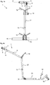
- FIG. 4a and 4b show two views of a frame 1 of a golf trolley with a frame support section 23, a frame middle section 22 and the guide rod 2.
- Support brackets 12 are used to place a golf club bag (not shown.); the legs can support the golf bag laterally.
- the frame 1 can be designed to be collapsible so that it can be stored in a space-saving manner when not in use.
- the locking wheel 14 can be released and the guide rod 2 can be folded over along the frame middle section 22 via the joint attached at this height.
- Not shown in the figure is an equally optional second joint with an analogous locking mechanism at the level of the rear wheel axle 15, via which the frame middle section 22 can also be arranged folded up along the frame support section 23.
- the trolley is equipped with an electric motor drive (not shown in the figure), which can be arranged within the rear wheel axle 15 or attached to the frame from the outside.
- the drive can, for example, advantageously be provided by modern stepper motors.
- Several wheels can also be equipped with their own drive units, but not all wheels have to be driven.
- the golf trolley can be connected to an external energy source via the connection socket 13 in order to to charge the battery (accumulator) for the electric motor drive or to be able to use a second accumulator as an additional energy source, whereby the performance is increased or the time until the next charge is extended.
- the guide rod 2 extends as part of the frame 1 above the upper support bracket 12 and has a control panel 9 and a handle bar 3 as the upper end.
- a handle 4 is arranged on the handle bar 3 of the guide rod 2.
- the guide rod forms a closed bracket and accordingly continues in both directions starting from the handle 4 in order to unite at a lower point on the other frame components.
- This embodiment is also according to the invention.
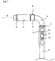
- Fig. 1 the upper section of the guide rod 2 is shown in a detailed view.
- the control panel 9 has several switches, two pressure switches 10 and a rotary switch 11 are shown by way of example. These can be used to set the driving speed and driving distance for an alternative operating mode in which the trolley drives independently. However, they can also be assigned ancillary functions, e.g. for setting lighting. However, since both the speed and the direction regulation can be carried out via the handle 4, such a control panel 9 or switch 10, 11 can also be completely omitted.
- the upper end of the guide rod 2 is designed as a handle bar 3 which is angled to the side at a 90 ° angle and to which the handle 4 is attached.
- the handle bar 3 is angled such that the upper, angled section carrying the handle 4 is aligned parallel to the rear wheel axis 15 of the frame 1 and thus orthogonally to a direction of movement of the trolley.
- the handle bar 3 is a separate component (cf. Fig. 2 ) and attached to the rest of the guide rod 2 via a two-part end ring 7.
- Other types of connection as well as a one-piece design of the guide rod 2 with a straight or angled handle bar 3 are alternatively possible.
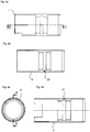
- Fig. 2 the handle bar 3 is shown without a handle 4; this does not mean that the handle 4 must be able to be dismantled, the view is only for illustration of the components that are covered by the handle 4 in the assembled final state for storage.
- Two springs 17 are arranged around the handle bar 3 opposite one another around the central axis of the handle bar 3 (angled section).
- the springs 17 can be implemented as tension or compression springs and have the effect that the grip piece, when it is placed on the springs 17, is translationally displaceable along the axis of rotation X.
- the springs exert a restoring force on the handle 4 so that it returns to its rest position if no deflecting force acts on it and the rest position is established as the starting position.
- compression springs 17 this means that when the handle 4 is moved out of the rest position, one of the two springs 17 is compressed and, in order to stretch again, the handle 4 pushes back into the rest position, while the other spring is analogous to one Moving in the opposite direction provides the restoring force.
- the spring strengths are chosen so that only a very low force is required for their deformation.
- the handle 4 can be rotated about the axis of rotation X, which corresponds to the central axis of the angled section of the guide rod 2 or its handle bar 3 and thus at the same time the central axis of the tubular handle 4.
- the grip 4 can therefore be moved around and along the axis of rotation X.
- a movement that is accompanied by a change in the axial alignment of the handle 4 or the position of the center axis of the handle 4, i.e. tilting or shifting transversely to the axis of rotation X, is not provided and at most to a small extent, technically due to the movable Storage for the intended deflections, possible.
- the handle 4 is in the rest position ("zero position"), from which the deflection in the direction of rotation by a certain angle or in the translational direction by a certain distance is made and determined by a magnetic field sensor (not shown).
- a magnet 20 is arranged in the handle, as in the sectional view of the handle 4 in FIG Figure 3b shown. It is a permanent magnet with small dimensions and light weight, so that the ergonomics of the handle are not negatively affected.
- the handle 4 is shown without magnet 20, but there is a recess 21 into which the magnet 20 is inserted.
- the handle can also be manufactured directly with an integrated magnet 20.
- the handle 4 (cf. Figures 3a to 3d ) is designed as a tubular piece (and therefore hollow on the inside), with an approximately circular cross-section ( Figure 3c ) so that it can be placed precisely on the guide rod 2.
- the jacket of the handle 4 must, as in Fig. 3d can be seen, not be continuous, but can have recesses in order to offer some flexibility when placing on and attaching to the guide rod 2.
- the outer contour of the handle can be shaped differently than shown.
- the guide rod 2 preferably has a magnetic field sensor directly opposite the magnet 20 when the handle 4 is installed and in the rest position.
- the seat 19 shown for the magnetic field sensor can be arranged so that it is covered by the handle 4 and the point on the handle 4 where the magnet 20 sits is not only in the rest position but also when the handle 4 is deflected always adjacent to the magnetic field sensor is located. In this way, the magnetic field of the magnet 20 is not weakened by other components.
- the magnetic field sensor registers changes in the magnetic field of the magnet 20 when the latter is also moved in its position due to a movement of the handle 4 and there is thus a relative movement between the magnet 20 and the magnetic field sensor. Even slight changes in position in the single-digit millimeter range can act as an operating signal, which is recorded and evaluated and implemented in the control unit, here a control board, of the golf trolley.
- control unit which can be arranged on any part of the frame 1, but here (not shown figuratively ) on the section of the guide rod 2 coming under the handle 4, e.g. B. is arranged within the tube of the angled section of the handlebar 3, an evaluation unit is included which determines certain control signals as a function of the deflection of the handle 4 detected by magnetic field detection.
- a certain angle through which the handle 4 is rotated about the axis of rotation can be associated with a certain speed, the control unit transmitting the necessary control signals for setting this speed of the trolley to the electric motor drive. This applies to the rotation in both directions, with the speed in the direction of rotation being set for forward or reverse travel. The following applies: the larger the angle, the higher the speed to be achieved.
- a certain distance by which the handle is shifted along the axis of rotation can be converted into a steering movement for a change of direction, the control unit controlling the drive or the steering with the signals determined by the evaluation unit.
- the change in direction can be greater, the greater the deflected distance.
- deflections to the right or left of the trolley which corresponds to the user's view when the latter is standing or walking behind the trolley, and the change in direction preferably to the left or right is triggered accordingly.
- the steering is therefore preferably controlled as if the entire golf trolley were being rotated manually with the steering movement on the handle 4.
- a limiting sleeve 5 is attached to its first end, which points in the direction in which the guide rod 2 continues.
- the limiting sleeve 5 also includes a push button 8, which can be operated, for example, to activate and deactivate the entire trolley, in particular its drive.
- a second (not visible) pushbutton can be arranged opposite the pushbutton 8 or at another point close to the handle 4 and, for example, activate a free-wheeling function of the golf trolley, i.e. specifically deactivate a braking function.
- a clamping ring 6 is arranged which can be slipped over the handle bar 3 after the handle 4 has been assembled.
- the golf trolley can be controlled by a golfer placing and securing his golf bag between the holding brackets 12 of the trolley and then gripping the handle 4, which is in the rest position, activating the drive and the control with a push of the push button 8 to rotate forwards (in the view of frame 1 of the trolley in Figure 4b this would correspond to a clockwise rotation) of the handle 4 with magnet 20.
- This is recorded and transmitted to the drive as a signal for driving forward; the trolley drives off.
- Reverse travel is analogous.
- the golfer brakes the trolley by turning it over or by turning it back to a rotation angle of 0 °. To turn right or left, he only has to move the handle 4 in the desired direction.
- the detected position of the magnet 20 in the handle 4 is converted into a strong steering movement corresponding to the deflection. Once the desired direction is set, the golfer reduces the pressure on the grip 4 to the right or left so that the grip 4 returns to the middle position and no steering movement is signaled. Then straight-ahead travel or a standstill is triggered again when the handle returns completely to its rest position.
Landscapes
- Engineering & Computer Science (AREA)
- Health & Medical Sciences (AREA)
- General Health & Medical Sciences (AREA)
- Physical Education & Sports Medicine (AREA)
- Chemical & Material Sciences (AREA)
- Combustion & Propulsion (AREA)
- Transportation (AREA)
- Mechanical Engineering (AREA)
- Handcart (AREA)
- Control Of Position, Course, Altitude, Or Attitude Of Moving Bodies (AREA)
Priority Applications (1)
| Application Number | Priority Date | Filing Date | Title |
|---|---|---|---|
| EP19000273.3A EP3747732A1 (fr) | 2019-06-05 | 2019-06-05 | Chariot de golf |
Applications Claiming Priority (1)
| Application Number | Priority Date | Filing Date | Title |
|---|---|---|---|
| EP19000273.3A EP3747732A1 (fr) | 2019-06-05 | 2019-06-05 | Chariot de golf |
Publications (1)
| Publication Number | Publication Date |
|---|---|
| EP3747732A1 true EP3747732A1 (fr) | 2020-12-09 |
Family
ID=66857598
Family Applications (1)
| Application Number | Title | Priority Date | Filing Date |
|---|---|---|---|
| EP19000273.3A Withdrawn EP3747732A1 (fr) | 2019-06-05 | 2019-06-05 | Chariot de golf |
Country Status (1)
| Country | Link |
|---|---|
| EP (1) | EP3747732A1 (fr) |
Cited By (1)
| Publication number | Priority date | Publication date | Assignee | Title |
|---|---|---|---|---|
| DE102022205396A1 (de) | 2022-05-30 | 2023-11-30 | Gebrüder Frei GmbH. & Co. KG | Griffelement für ein modulares Bediensystem |
Citations (6)
| Publication number | Priority date | Publication date | Assignee | Title |
|---|---|---|---|---|
| US5789884A (en) * | 1996-03-25 | 1998-08-04 | Hancock; Frank John Thompson | Control arrangement for motorised trolley |
| DE20307742U1 (de) | 2003-01-22 | 2003-07-31 | Wahler Peter | Trolley zum Transport einer Golftasche |
| DE20221472U1 (de) * | 2002-09-04 | 2006-01-12 | Lang, Emil | Trolley mit einem motorisch antreibbaren Laufwerk |
| DE202007005290U1 (de) | 2007-04-12 | 2007-06-21 | Kiffe Engineering Gmbh | Golf-Caddie |
| EP2644232A1 (fr) | 2012-03-30 | 2013-10-02 | giwa-tec GmbH | Chariot de golf à commande intuitive et roues d'un nouveau type |
| GB2542258A (en) * | 2015-07-31 | 2017-03-15 | Fifteenine Ltd | Golfing equipment |
-
2019
- 2019-06-05 EP EP19000273.3A patent/EP3747732A1/fr not_active Withdrawn
Patent Citations (6)
| Publication number | Priority date | Publication date | Assignee | Title |
|---|---|---|---|---|
| US5789884A (en) * | 1996-03-25 | 1998-08-04 | Hancock; Frank John Thompson | Control arrangement for motorised trolley |
| DE20221472U1 (de) * | 2002-09-04 | 2006-01-12 | Lang, Emil | Trolley mit einem motorisch antreibbaren Laufwerk |
| DE20307742U1 (de) | 2003-01-22 | 2003-07-31 | Wahler Peter | Trolley zum Transport einer Golftasche |
| DE202007005290U1 (de) | 2007-04-12 | 2007-06-21 | Kiffe Engineering Gmbh | Golf-Caddie |
| EP2644232A1 (fr) | 2012-03-30 | 2013-10-02 | giwa-tec GmbH | Chariot de golf à commande intuitive et roues d'un nouveau type |
| GB2542258A (en) * | 2015-07-31 | 2017-03-15 | Fifteenine Ltd | Golfing equipment |
Cited By (1)
| Publication number | Priority date | Publication date | Assignee | Title |
|---|---|---|---|---|
| DE102022205396A1 (de) | 2022-05-30 | 2023-11-30 | Gebrüder Frei GmbH. & Co. KG | Griffelement für ein modulares Bediensystem |
Similar Documents
| Publication | Publication Date | Title |
|---|---|---|
| DE102005006574B3 (de) | Rollstuhl mit Fernbedienung | |
| EP1799911B1 (fr) | Plaque vibrante à télécommande intégrée dans le timon | |
| DE1763005C3 (de) | Steuerknüppel-Fahrschalter für Elektrofahrzeuge | |
| EP2750653B1 (fr) | Dispositif thérapeutique d'entraînement à la marche | |
| DE102015000270A1 (de) | Mobile Geh- und Transporthilfe-Vorrichtung | |
| EP3212146A1 (fr) | Table d'opération et plate-forme de plancher pour table d'opération | |
| EP3173056B1 (fr) | Dispositif d'entraînement auxiliaire et fauteuil roulant le comprenant | |
| EP2669124A1 (fr) | Système de rangement de remorque avec télécommande | |
| EP2895373A1 (fr) | Véhicule à main et ensemble de rééquipement pour convertir un tel véhicule | |
| DE102010020318B4 (de) | Bedieneinheit für elektromotorisch angetriebene Fahrzeuge, insbesondere Zugeinheit oder Schiebehilfe für einen Rollstuhl oder Flurförderfahrzeug | |
| EP3514047A1 (fr) | Commande de freinage sans fil | |
| WO1997005010A1 (fr) | Vehicule a roues entraine par la force musculaire et par un mecanisme auxiliaire d'entrainement electrique | |
| DE102006032843B4 (de) | Zusatzantriebsvorrichtung für manuelle Rollstühle | |
| EP3347263A1 (fr) | Véhicule à équilibrage dynamique | |
| EP3747732A1 (fr) | Chariot de golf | |
| DE10309621A1 (de) | Motorgetriebenes, handgeführtes Transportfahrzeug mit intuitiver Haltegriffsteuerung | |
| DE202007005290U1 (de) | Golf-Caddie | |
| DE202007008851U1 (de) | Akku-Kinderwagen | |
| EP3853100A1 (fr) | Châssis de poussette et poussette | |
| EP3539521A1 (fr) | Fauteuil roulant | |
| DE3923809A1 (de) | Golfwagen | |
| DE102016006297A1 (de) | Transportmittel mit fernsteuerbarer Arretierung | |
| DE202010001916U1 (de) | Gehhilfe zur Unterstützung der Fortbewegung einer gehbehinderten Person | |
| EP3999400A1 (fr) | Poussette | |
| DE102017130681B3 (de) | Vorspannlenkvorrichtung für einen Rollstuhl und Rollstuhlgespann mit Vorspannlenkvorrichtung |
Legal Events
| Date | Code | Title | Description |
|---|---|---|---|
| PUAI | Public reference made under article 153(3) epc to a published international application that has entered the european phase |
Free format text: ORIGINAL CODE: 0009012 |
|
| STAA | Information on the status of an ep patent application or granted ep patent |
Free format text: STATUS: THE APPLICATION HAS BEEN PUBLISHED |
|
| AK | Designated contracting states |
Kind code of ref document: A1 Designated state(s): AL AT BE BG CH CY CZ DE DK EE ES FI FR GB GR HR HU IE IS IT LI LT LU LV MC MK MT NL NO PL PT RO RS SE SI SK SM TR |
|
| AX | Request for extension of the european patent |
Extension state: BA ME |
|
| STAA | Information on the status of an ep patent application or granted ep patent |
Free format text: STATUS: REQUEST FOR EXAMINATION WAS MADE |
|
| 17P | Request for examination filed |
Effective date: 20210526 |
|
| RBV | Designated contracting states (corrected) |
Designated state(s): AL AT BE BG CH CY CZ DE DK EE ES FI FR GB GR HR HU IE IS IT LI LT LU LV MC MK MT NL NO PL PT RO RS SE SI SK SM TR |
|
| GRAP | Despatch of communication of intention to grant a patent |
Free format text: ORIGINAL CODE: EPIDOSNIGR1 |
|
| STAA | Information on the status of an ep patent application or granted ep patent |
Free format text: STATUS: GRANT OF PATENT IS INTENDED |
|
| INTG | Intention to grant announced |
Effective date: 20221201 |
|
| STAA | Information on the status of an ep patent application or granted ep patent |
Free format text: STATUS: THE APPLICATION IS DEEMED TO BE WITHDRAWN |
|
| 18D | Application deemed to be withdrawn |
Effective date: 20230412 |