EP3746830B1 - Système optique d'un stéréo-vidéo-endoscope - Google Patents
Système optique d'un stéréo-vidéo-endoscope Download PDFInfo
- Publication number
- EP3746830B1 EP3746830B1 EP19702368.2A EP19702368A EP3746830B1 EP 3746830 B1 EP3746830 B1 EP 3746830B1 EP 19702368 A EP19702368 A EP 19702368A EP 3746830 B1 EP3746830 B1 EP 3746830B1
- Authority
- EP
- European Patent Office
- Prior art keywords
- lens
- light
- coating
- outlet
- optical system
- Prior art date
- Legal status (The legal status is an assumption and is not a legal conclusion. Google has not performed a legal analysis and makes no representation as to the accuracy of the status listed.)
- Active
Links
Images

Classifications
-
- G—PHYSICS
- G02—OPTICS
- G02B—OPTICAL ELEMENTS, SYSTEMS OR APPARATUS
- G02B23/00—Telescopes, e.g. binoculars; Periscopes; Instruments for viewing the inside of hollow bodies; Viewfinders; Optical aiming or sighting devices
- G02B23/24—Instruments or systems for viewing the inside of hollow bodies, e.g. fibrescopes
- G02B23/2407—Optical details
- G02B23/2423—Optical details of the distal end
- G02B23/243—Objectives for endoscopes
-
- A—HUMAN NECESSITIES
- A61—MEDICAL OR VETERINARY SCIENCE; HYGIENE
- A61B—DIAGNOSIS; SURGERY; IDENTIFICATION
- A61B1/00—Instruments for performing medical examinations of the interior of cavities or tubes of the body by visual or photographical inspection, e.g. endoscopes; Illuminating arrangements therefor
- A61B1/00064—Constructional details of the endoscope body
- A61B1/00066—Proximal part of endoscope body, e.g. handles
-
- A—HUMAN NECESSITIES
- A61—MEDICAL OR VETERINARY SCIENCE; HYGIENE
- A61B—DIAGNOSIS; SURGERY; IDENTIFICATION
- A61B1/00—Instruments for performing medical examinations of the interior of cavities or tubes of the body by visual or photographical inspection, e.g. endoscopes; Illuminating arrangements therefor
- A61B1/00064—Constructional details of the endoscope body
- A61B1/00071—Insertion part of the endoscope body
- A61B1/0008—Insertion part of the endoscope body characterised by distal tip features
- A61B1/00096—Optical elements
-
- A—HUMAN NECESSITIES
- A61—MEDICAL OR VETERINARY SCIENCE; HYGIENE
- A61B—DIAGNOSIS; SURGERY; IDENTIFICATION
- A61B1/00—Instruments for performing medical examinations of the interior of cavities or tubes of the body by visual or photographical inspection, e.g. endoscopes; Illuminating arrangements therefor
- A61B1/00163—Optical arrangements
- A61B1/00174—Optical arrangements characterised by the viewing angles
- A61B1/00183—Optical arrangements characterised by the viewing angles for variable viewing angles
-
- A—HUMAN NECESSITIES
- A61—MEDICAL OR VETERINARY SCIENCE; HYGIENE
- A61B—DIAGNOSIS; SURGERY; IDENTIFICATION
- A61B1/00—Instruments for performing medical examinations of the interior of cavities or tubes of the body by visual or photographical inspection, e.g. endoscopes; Illuminating arrangements therefor
- A61B1/00163—Optical arrangements
- A61B1/00193—Optical arrangements adapted for stereoscopic vision
-
- G—PHYSICS
- G02—OPTICS
- G02B—OPTICAL ELEMENTS, SYSTEMS OR APPARATUS
- G02B23/00—Telescopes, e.g. binoculars; Periscopes; Instruments for viewing the inside of hollow bodies; Viewfinders; Optical aiming or sighting devices
- G02B23/24—Instruments or systems for viewing the inside of hollow bodies, e.g. fibrescopes
- G02B23/2407—Optical details
- G02B23/2415—Stereoscopic endoscopes
-
- G—PHYSICS
- G02—OPTICS
- G02B—OPTICAL ELEMENTS, SYSTEMS OR APPARATUS
- G02B23/00—Telescopes, e.g. binoculars; Periscopes; Instruments for viewing the inside of hollow bodies; Viewfinders; Optical aiming or sighting devices
- G02B23/24—Instruments or systems for viewing the inside of hollow bodies, e.g. fibrescopes
- G02B23/2407—Optical details
- G02B23/2423—Optical details of the distal end
-
- G—PHYSICS
- G02—OPTICS
- G02B—OPTICAL ELEMENTS, SYSTEMS OR APPARATUS
- G02B23/00—Telescopes, e.g. binoculars; Periscopes; Instruments for viewing the inside of hollow bodies; Viewfinders; Optical aiming or sighting devices
- G02B23/24—Instruments or systems for viewing the inside of hollow bodies, e.g. fibrescopes
- G02B23/2407—Optical details
- G02B23/2453—Optical details of the proximal end
-
- G—PHYSICS
- G02—OPTICS
- G02B—OPTICAL ELEMENTS, SYSTEMS OR APPARATUS
- G02B27/00—Optical systems or apparatus not provided for by any of the groups G02B1/00 - G02B26/00, G02B30/00
- G02B27/0018—Optical systems or apparatus not provided for by any of the groups G02B1/00 - G02B26/00, G02B30/00 with means for preventing ghost images
-
- A—HUMAN NECESSITIES
- A61—MEDICAL OR VETERINARY SCIENCE; HYGIENE
- A61B—DIAGNOSIS; SURGERY; IDENTIFICATION
- A61B1/00—Instruments for performing medical examinations of the interior of cavities or tubes of the body by visual or photographical inspection, e.g. endoscopes; Illuminating arrangements therefor
- A61B1/04—Instruments for performing medical examinations of the interior of cavities or tubes of the body by visual or photographical inspection, e.g. endoscopes; Illuminating arrangements therefor combined with photographic or television appliances
- A61B1/05—Instruments for performing medical examinations of the interior of cavities or tubes of the body by visual or photographical inspection, e.g. endoscopes; Illuminating arrangements therefor combined with photographic or television appliances characterised by the image sensor, e.g. camera, being in the distal end portion
Definitions
- the invention relates to an optical system of a stereo video endoscope with a lateral viewing direction, comprising a sideways-looking distal optical assembly and a proximal optical assembly, wherein the distal optical assembly comprises, in a light incidence direction, an entrance lens, a deflection unit designed as a prism unit and an exit lens on a common optical axis, and wherein the proximal optical assembly comprises a left and a right lens system channel, wherein the lens system channels are of similar construction and arranged parallel to one another and each have their own optical axis.
- the invention further relates to a stereo video endoscope with a lateral, in particular fixed, viewing direction and to a use of a lens for an optical system of a stereo video endoscope.
- Video endoscopes in which the lens attached to a distal tip of an endoscope shaft Incoming light is directed by an optical system to one or more image sensors, and is available in various designs.
- Stereo video endoscopes are also known which are designed to record a stereoscopic image pair and/or two stereoscopic video channels. With such instruments it is possible to create a 3D image of an object located distally in front of the end of the endoscope shaft in an examination or operating room.
- Stereo video endoscopes with a lateral view are endoscopes that look sideways and have a fixed viewing angle that deviates from the straight-ahead view.
- Such endoscopes often include a prism arrangement made up of several prisms that reflect the light rays entering the optical system from the object space at an angle to the longitudinal axis of the endoscope shaft twice and redirect them in the correct direction towards the endoscope shaft.
- Such an endoscope is known, for example, from the EN 10 2014 206 513 A1 Olympus Winter & Ibe GmbH, Hamburg.
- a deflection prism arrangement of such a stereo video endoscope typically comprises two or three prisms.
- the prisms are often cemented together at their common interfaces.
- the reflection of the incident light beams takes place at two reflecting interfaces of a second or third prism that are inclined both to the optical axis of the entrance lens and to the longitudinal axis of the endoscope shaft.
- the second or third prism of the The deflection prism arrangement is located in the direction of light incidence behind a first or second prism, which is arranged behind the entrance lens.
- the inclined reflecting interface of the second or third prism, at which the second reflection takes place partially forms a common interface with the front prism, through which the incident light rays pass first.
- the entrance lens of the optical system of such a stereo video endoscope defines the optical axis of the optical system.
- the optical system comprises apertures or menisci that define a field of view or the opening angle of the optics.
- Light beams entering the optical system within the field of view are imaged by the optical system onto one or more image sensors.
- Light beams entering the optical system from outside the field of view or through multiple reflections create so-called "ghost images" or "flares”.
- a known deflection prism group in which such ghost images can arise comprises a first prism and a second prism which are cemented together.
- the first prism has an entrance side and an exit side, the entrance side being inclined relative to the exit side.
- the exit side of the first prism is directly adjacent to a second entrance side of the second prism.
- the first and second prisms are cemented together on these two sides.
- the second prism also comprises a reflection side and a second exit side. Light which enters the deflection prism group from the image field passes through the entrance side of the first prism and exits again at its exit side. The light then passes directly through the second entrance side into the second prism, is reflected on the reflection side within the second prism and leaves it at the exit side.
- US5,689,365 A1 discloses a stereo video endoscope in which a distal optical assembly with a lateral viewing direction is provided. In relation to the direction of light incidence, a proximal optical assembly with two lens system channels is arranged behind the distal optical assembly.
- optical system for endoscopes which is arranged on the distal side of the endoscope.
- the optical system has, in order of the image side, a single lens with a negative refractive power, a cemented lens with a positive refractive power and an image sensor unit.
- US 2016/0370580 A1 a manufacture of an optical element, wherein ink containing a light-blocking material is applied to a surface of an optical body by means of an inkjet printing process.
- US 2017/0235121 A1 discloses an endoscope optical lens system, wherein in case of a close distance between a front and a rear optical group, an intermediate aperture stop is attached to a lens surface.
- the object of the invention is to prevent the formation of ghost images in a stereo video endoscope in a simple manner.
- an optical system of a stereo video endoscope with a lateral viewing direction comprising a sideways-looking distal optical assembly and a proximal optical assembly, wherein the distal optical assembly is arranged in a proximal optical assembly comprises a left and a right lens system channel, wherein the lens system channels are constructed in the same way and arranged parallel to one another and each have their own optical axis, which is further developed in that the exit lens in the middle region of the exit lens is formed with an opaque coating on its light entry side facing the deflection unit and/or with an opaque coating on its light exit side facing away from the deflection unit.
- the invention is based on the idea that the exit lens of the distal optical assembly, which is preferably arranged on the prism unit of the distal optical assembly, is provided with a coating, whereby no light passes through the exit lens in the central region and the formation of ghost images in the lens system channels is minimized or prevented.
- the exit lens is preferably designed as a prism lens, with the light rays for the left and right optical channels
- Light incidence direction successively comprises an entrance lens, a deflection unit designed as a prism unit and an exit lens on a common optical axis
- the proximal optical assembly comprises a left and a right lens system channel, wherein the lens system channels are constructed identically and arranged parallel to one another and each have their own optical axis, which is further developed in that the exit lens is formed with an opaque coating on its light exit side facing away from the deflection unit.
- the invention is based on the idea that the exit lens of the distal optical assembly, which is preferably arranged on the prism unit of the distal optical assembly, is provided with a coating, whereby no light passes through the exit lens in the central region and the formation of ghost images in the lens system channels is minimized or prevented.
- the exit lens is preferably designed as a prism lens, with the light rays for the left and right optical channels being allowed to pass between the region of the light-transmissive coating on the exit lens and the outer edge of the exit lens. In the central region of the exit lens, in which the coating or coatings are applied to the exit lens, no light rays are allowed to pass. Due to the coating or coatings, the exit lens has an annular or ring-like optical transmission region.
- the exit lens is formed with an opaque coating in the central region of the exit lens on its light entry side facing the deflection unit.
- the coating on the exit lens is circular or circular-shaped on its light exit side facing away from the deflection unit and/or that the coating on the exit lens is circular or circular-shaped on its light exit side facing the deflection unit.
- the exit lens is transparent to the left lens system channel and the right lens system channel of the proximal optical assembly, wherein in particular the optical transmission region of the exit lens is formed in a ring-like manner or in a ring-shaped manner outside the coating(s).
- the side of the exit lens facing away from the deflection unit is convex.
- the exit lens is designed as a concave-convex lens.
- the coating on the exit lens on its light exit side facing away from the deflection unit is designed as an anti-reflective coating and/or that the coating on the exit lens on its light exit side facing the deflection unit is designed as an anti-reflective coating.
- a coating is provided as an anti-reflective coating in order to reduce or avoid the formation of flares or ghost images.
- the opaque coating or the anti-reflective coating is formed as a chrome coating.
- the object is achieved by a stereo video endoscope with a fixed, preferably lateral, viewing direction with an optical system as described above.
- the optical system comprises one or more of the previously mentioned embodiments.
- the object is achieved by using a lens for an optical system of a stereo video endoscope with a fixed viewing direction, wherein the optical system is designed according to the embodiments mentioned above, wherein the lens is designed as an exit lens of a distal optical assembly and is formed with an opaque coating in the central region of the exit lens on its light exit side facing away from a deflection unit of the distal optical assembly.
- Embodiments of the invention may fulfill individual features or a combination of several features.
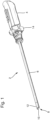
- Fig.1 shows a simplified perspective view of a known endoscope 2 with a proximal handle 4 and a rigid endoscope shaft 6.
- a viewing window 10 is located at a distal tip 8 of the endoscope shaft 6.
- An optical system (not visible) is arranged with which an examination or operation area located in front of the distal tip 8 of the endoscope 2 is imaged on image sensors (also not shown).
- a rotary wheel 14 is connected to the handle 4 in the distal direction, with which the optical system located inside the endoscope shaft 6 can be rotated azimuthally.
- Fig.2 shows in a simplified schematic sectional view a optical system, such as that found in EN 10 2013 215 422 A1 Olympus Winter & Ibe GmbH, Hamburg.
- the optical system comprises a sideways-looking distal optical assembly 16, which is arranged behind the entrance window 10.
- the optical system shown is located in the distal section 12 of the Fig.1 shown stereo video endoscope 2.
- the optical system comprises a proximal optical assembly 18. This can be rotated, for example, by turning the rotary wheel 14 in the endoscope shaft 6.
- the distal optical assembly 16 comprises an entrance lens 20, which is designed, for example, as a raised negative meniscus. It comprises a convex outer surface 22 and a concave inner surface 24.
- the light entering from the left side through the viewing window 10 passes through the entrance lens 20 and falls into a deflection unit 26 designed as a prism unit.
- This comprises two prisms with a partially mirrored or mirrored interface.
- the light incident obliquely from the side is deflected by the deflection unit 26 in the direction of a longitudinal axis of the endoscope shaft 6.
- the deflection unit 26 comprises a first partially mirrored prism 28, which comprises the partially mirrored interface 26b.
- the deflection unit 26 also comprises a further partially mirrored prism 30, which is not shown in detail and comprises the mirrored interface 26a.
- the distal optical assembly 16 comprises an exit lens 32, which is arranged behind a diaphragm 34 in the direction of light incidence.
- a diaphragm 34 in the direction of light incidence.
- rod lenses 40L, 40R of the proximal optical assemblies 18 are arranged for a left lens system channel 38L and a right lens system channel 38R each aperture arranged.
- the light enters the exit lens 32 from the deflection unit 26.
- the exit lens 32 is designed as a hollow positive meniscus lens, for example. It has a concave entrance surface 36a and a convex exit surface 36b.
- the radius of curvature of the concave entrance surface 36a is larger than the radius of curvature of the convex exit surface 36b.
- the light emerging from the exit lens 32 reaches the proximal optical assembly 18.
- This comprises a left lens system channel 38L and a right lens system channel 38R.
- the two lens system channels 38L, 38R are constructed in the same way and are arranged parallel to one another.
- the left optical channel has a left optical axis LoA and the right optical channel has a right optical axis RoA.
- the optical axes LoA, RoA are oriented at least approximately parallel to one another.
- the two lens system channels 38L, 38R each comprise a rod lens 40L, 40R, into which the light first enters from the exit lens 32 of the distal optical assembly 16.
- the left and right rod lenses 40L, 40R are each followed in the direction of light incidence by an achromatic lens group 42L, 42R.
- the achromatic lens groups 42L, 42R are each designed as triplets. The light from these is directed onto the left or right image sensor 44L, 44R, so that the examination or operating area located in front of the distal tip 8 of the endoscope shaft 6 is imaged stereoscopically.
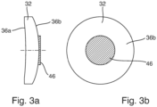
- Fig. 3a and 3b are a cross-sectional view ( Fig. 3a ) and a front view ( Fig. 3b ) of an exit lens 32 of the distal optical unit 16 (cf. Fig.2 ) according to an embodiment of the invention.
- the exit lens 32 is designed as a concave-convex lens with a concave entrance surface 36a and a convex exit surface 36b.
- a circular coating 46 is formed in the middle area on the convex exit surface 36b, so that in the area of the coating 46 no light is allowed through from the coating 46 in the middle area.
- the coating is formed as a circular area on the convex exit surface.
- the coating 46 is formed as a chrome coating.
Landscapes
- Physics & Mathematics (AREA)
- Health & Medical Sciences (AREA)
- Life Sciences & Earth Sciences (AREA)
- Optics & Photonics (AREA)
- Surgery (AREA)
- General Physics & Mathematics (AREA)
- General Health & Medical Sciences (AREA)
- Radiology & Medical Imaging (AREA)
- Astronomy & Astrophysics (AREA)
- Molecular Biology (AREA)
- Medical Informatics (AREA)
- Engineering & Computer Science (AREA)
- Biomedical Technology (AREA)
- Heart & Thoracic Surgery (AREA)
- Nuclear Medicine, Radiotherapy & Molecular Imaging (AREA)
- Animal Behavior & Ethology (AREA)
- Pathology (AREA)
- Biophysics (AREA)
- Public Health (AREA)
- Veterinary Medicine (AREA)
- Instruments For Viewing The Inside Of Hollow Bodies (AREA)
- Endoscopes (AREA)
- Optical Elements Other Than Lenses (AREA)
Claims (10)
- Système optique d'un vidéo-endoscope stéréo (2) à vision latérale, comprenant un ensemble optique distal (16) à vision latérale et un ensemble optique proximal (18), l'ensemble optique distal (16) comprenant successivement, dans une direction d'incidence de la lumière, une lentille d'entrée (20), une unité de déviation (26) conçue sous la forme d'une unité formant prisme et une lentille de sortie (32) sur un axe optique commun, et l'ensemble optique proximal (18) comprenant un canal de système de lentilles gauche et un canal de système de lentilles droit (38L, 38R), les canaux de système de lentilles (38L, 38R) étant de construction identique et disposés parallèlement l'un à l'autre et présentant chacun un axe optique propre (LoA, RoA), caractérisé en ce que la lentille de sortie (32) est réalisée avec un revêtement opaque (46) dans la zone centrale de la lentille de sortie (32) sur son côté de sortie de lumière (36b) opposé à l'unité de déviation (26).
- Système optique selon la revendication 1, caractérisé en ce que la lentille de sortie (32) est réalisée avec un revêtement opaque (46) dans la zone centrale de la lentille de sortie (32) sur son côté d'entrée de lumière (36a) tourné vers l'unité de déviation (26).
- Système optique selon la revendication 1 ou la revendication 2, caractérisé en ce que le revêtement (46) sur la lentille de sortie sur son côté de sortie de lumière (36b) opposé à l'unité de déviation (26) est de forme circulaire ou de type circulaire, et/ou en ce que le revêtement (46) sur la lentille de sortie sur son côté de sortie de lumière (36a) tourné vers l'unité de déviation (26) est de forme circulaire ou de type circulaire.
- Système optique selon l'une des revendications 1 à 3, caractérisé en ce que la lentille de sortie (32) du canal gauche (38L) du système de lentilles et du canal droit (38R) du système de lentilles de l'ensemble optique proximal (18) est translucide.
- Système optique selon l'une des revendications 1 à 4, caractérisé en ce que la face de la lentille de sortie (32) opposée à l'unité de déviation (26) est convexe.
- Système optique selon l'une des revendications 1 à 5, caractérisé en ce que la lentille de sortie (32) est conçue sous la forme d'une lentille concave-convexe.
- Système optique selon l'une des revendications 1 à 6, caractérisé en ce que le revêtement (46) sur la lentille de sortie (32) est réalisé sous forme de revêtement antireflet (46) sur son côté de sortie de lumière (36b) opposé à l'unité de déviation (26), et/ou en ce que le revêtement (46) sur la lentille de sortie (32) est réalisé sous forme de revêtement antireflet (46) sur son côté de sortie de lumière (36a) tourné vers l'unité de déviation (26).
- Système optique selon la revendication 7, caractérisé en ce que le revêtement antireflet (46) est réalisé sous forme de revêtement chromé (46).
- Vidéo-endoscope stéréo (2) à direction de vision fixe, comprenant un système optique (20) selon l'une des revendications 1 à 8.
- Utilisation d'une lentille (32) pour un système optique (20) d'un vidéo-endoscope stéréo (2) à direction de vision fixe selon l'une des revendications 1 à 8, dans laquelle la lentille (32) est réalisée sous forme de lentille de sortie (32) d'un ensemble optique distal (16) et est réalisée dans la zone centrale de la lentille de sortie (32) sur son côté de sortie de lumière (36b) opposé à une unité de déviation (26) de l'ensemble optique distal (16) avec un revêtement opaque (46).
Priority Applications (1)
| Application Number | Priority Date | Filing Date | Title |
|---|---|---|---|
| EP24176244.2A EP4394481A3 (fr) | 2018-02-01 | 2019-01-24 | Système optique d'un stéréo-vidéo-endoscope |
Applications Claiming Priority (2)
| Application Number | Priority Date | Filing Date | Title |
|---|---|---|---|
| DE102018102268.9A DE102018102268A1 (de) | 2018-02-01 | 2018-02-01 | Optisches System eines Stereo-Videoendoskops |
| PCT/EP2019/051700 WO2019149609A1 (fr) | 2018-02-01 | 2019-01-24 | Système optique d'un stéréo-vidéo-endoscope |
Related Child Applications (2)
| Application Number | Title | Priority Date | Filing Date |
|---|---|---|---|
| EP24176244.2A Division EP4394481A3 (fr) | 2018-02-01 | 2019-01-24 | Système optique d'un stéréo-vidéo-endoscope |
| EP24176244.2A Division-Into EP4394481A3 (fr) | 2018-02-01 | 2019-01-24 | Système optique d'un stéréo-vidéo-endoscope |
Publications (2)
| Publication Number | Publication Date |
|---|---|
| EP3746830A1 EP3746830A1 (fr) | 2020-12-09 |
| EP3746830B1 true EP3746830B1 (fr) | 2024-07-31 |
Family
ID=65243533
Family Applications (2)
| Application Number | Title | Priority Date | Filing Date |
|---|---|---|---|
| EP24176244.2A Pending EP4394481A3 (fr) | 2018-02-01 | 2019-01-24 | Système optique d'un stéréo-vidéo-endoscope |
| EP19702368.2A Active EP3746830B1 (fr) | 2018-02-01 | 2019-01-24 | Système optique d'un stéréo-vidéo-endoscope |
Family Applications Before (1)
| Application Number | Title | Priority Date | Filing Date |
|---|---|---|---|
| EP24176244.2A Pending EP4394481A3 (fr) | 2018-02-01 | 2019-01-24 | Système optique d'un stéréo-vidéo-endoscope |
Country Status (5)
| Country | Link |
|---|---|
| US (1) | US11391939B2 (fr) |
| EP (2) | EP4394481A3 (fr) |
| JP (1) | JP7023374B2 (fr) |
| DE (1) | DE102018102268A1 (fr) |
| WO (1) | WO2019149609A1 (fr) |
Families Citing this family (1)
| Publication number | Priority date | Publication date | Assignee | Title |
|---|---|---|---|---|
| DE102016214272A1 (de) * | 2016-08-02 | 2018-02-22 | Olympus Winter & Ibe Gmbh | Optisches System eines Stereo-Videoendoskops mit seitlicher Blickrichtung sowie Verfahren zum Herstellen desselben |
Citations (1)
| Publication number | Priority date | Publication date | Assignee | Title |
|---|---|---|---|---|
| US20170235121A1 (en) * | 2015-05-28 | 2017-08-17 | Olympus Corporation | Endoscope objective optical system |
Family Cites Families (14)
| Publication number | Priority date | Publication date | Assignee | Title |
|---|---|---|---|---|
| JPH04138402A (ja) * | 1990-09-28 | 1992-05-12 | Minolta Camera Co Ltd | 写真レンズ |
| US5341240A (en) * | 1992-02-06 | 1994-08-23 | Linvatec Corporation | Disposable endoscope |
| JP3580869B2 (ja) * | 1994-09-13 | 2004-10-27 | オリンパス株式会社 | 立体視内視鏡 |
| US6682478B2 (en) * | 2001-02-08 | 2004-01-27 | Olympus Optical Co., Ltd. | Endoscope apparatus with an insertion part having a small outer diameter which includes and object optical system |
| EP1542053B1 (fr) * | 2003-12-11 | 2007-11-14 | Tokendo | Dispositif de métrologie pour sonde vidéoendoscopique |
| JP2005223716A (ja) | 2004-02-06 | 2005-08-18 | Rohm Co Ltd | イメージセンサモジュールおよびイメージセンサモジュール用レンズユニット |
| JP2009288682A (ja) * | 2008-05-30 | 2009-12-10 | Olympus Medical Systems Corp | 内視鏡対物光学系 |
| DE102013215422B4 (de) | 2013-08-06 | 2022-02-24 | Olympus Winter & Ibe Gmbh | Optisches System eines Stereo-Videoendoskops mit seitlicher Blickrichtung und Stereo-Videoendoskop mit seitlicher Blickrichtung |
| WO2015133431A1 (fr) * | 2014-03-03 | 2015-09-11 | 富士フイルム株式会社 | Élément optique, unité de lentille, module de capture d'images, dispositif numérique et procédé de fabrication d'un élément optique |
| DE102014206513A1 (de) | 2014-04-04 | 2015-10-08 | Olympus Winter & Ibe Gmbh | Stereoskopisches Endoskopsystem und Endoskop, Montageverfahren |
| IL236418A (en) | 2014-12-23 | 2016-07-31 | Visionsense Ltd | Stereo endoscope with tiltable, rotatable view |
| US10036883B2 (en) * | 2015-09-07 | 2018-07-31 | Hoya Corporation | Endoscope magnification optical system and endoscope |
| JP6704413B2 (ja) * | 2015-12-17 | 2020-06-03 | オリンパス株式会社 | 内視鏡用光学アダプタ |
| DE102016122429A1 (de) | 2016-11-22 | 2018-05-24 | Karl Storz Se & Co. Kg | Negativlinse und Endoskopobjektiv |
-
2018
- 2018-02-01 DE DE102018102268.9A patent/DE102018102268A1/de active Pending
-
2019
- 2019-01-24 EP EP24176244.2A patent/EP4394481A3/fr active Pending
- 2019-01-24 JP JP2020542096A patent/JP7023374B2/ja active Active
- 2019-01-24 WO PCT/EP2019/051700 patent/WO2019149609A1/fr not_active Ceased
- 2019-01-24 EP EP19702368.2A patent/EP3746830B1/fr active Active
-
2020
- 2020-07-30 US US16/943,461 patent/US11391939B2/en active Active
Patent Citations (1)
| Publication number | Priority date | Publication date | Assignee | Title |
|---|---|---|---|---|
| US20170235121A1 (en) * | 2015-05-28 | 2017-08-17 | Olympus Corporation | Endoscope objective optical system |
Also Published As
| Publication number | Publication date |
|---|---|
| JP7023374B2 (ja) | 2022-02-21 |
| EP4394481A3 (fr) | 2024-09-04 |
| JP2021512372A (ja) | 2021-05-13 |
| US20200355909A1 (en) | 2020-11-12 |
| WO2019149609A1 (fr) | 2019-08-08 |
| DE102018102268A1 (de) | 2019-08-01 |
| EP3746830A1 (fr) | 2020-12-09 |
| EP4394481A2 (fr) | 2024-07-03 |
| US11391939B2 (en) | 2022-07-19 |
Similar Documents
| Publication | Publication Date | Title |
|---|---|---|
| DE102013215422B4 (de) | Optisches System eines Stereo-Videoendoskops mit seitlicher Blickrichtung und Stereo-Videoendoskop mit seitlicher Blickrichtung | |
| EP1862837B1 (fr) | Optique d'imagerie à spectres multiples | |
| DE2638999C3 (de) | Objektiv für Sichtgeräte mit Faseroptik | |
| DE3447893C2 (fr) | ||
| WO2015055282A1 (fr) | Endoscope à direction de visée réglable | |
| EP3494431B1 (fr) | Système optique d'un stéréo-vidéo-endoscope pourvu d'un champ de vision latéral et procédé de fabrication de ce dernier | |
| EP3276390B1 (fr) | Système optique et instrument chirurgical comprenant un tel système optique | |
| EP1000374A2 (fr) | Objectif d'endoscope | |
| DE102016219217B4 (de) | Winkelselektives optisches System, Stereo-Videoendoskop mit einem solchen System sowie Verfahren zum Herstellen desselben | |
| DE102022124306A1 (de) | Visualisierungssystem mit optimiertem Umlenkprisma | |
| WO2015150078A1 (fr) | Système endoscopique stéréoscopique et endoscope, procédé de montage | |
| EP3694388B1 (fr) | Système optique pour une caméra stéréoscopique | |
| EP3555686B1 (fr) | Système optique pour un endoscope à visée latérale ainsi qu'endoscope à visée latérale | |
| EP3746830B1 (fr) | Système optique d'un stéréo-vidéo-endoscope | |
| WO2019175044A1 (fr) | Système optique d'un stéréo-vidéo-endoscope et procédé de fabrication de ce dernier | |
| EP3749999B1 (fr) | Système optique d'un endoscope, endoscope, endoscope vidéo stéréoscopique et procédé de fabrication d'un système optique | |
| DE102018116139B4 (de) | Optisches System und Stereo-Videoendoskop | |
| DE102014211367A1 (de) | Prismenvorrichtung und Endoskop | |
| EP1088251A1 (fr) | Systeme d'adaptateur optique pour un appareil de prise de vues | |
| DE102019100809A1 (de) | Optisches System eines Endoskop und Endoskop | |
| DE2430148C3 (de) | Endoskop mit zwischen Geradsicht und Seitensicht veränderlicher Blickrichtung, bei welchem ein Faserbündel zur Übertragung des mittels eines Objektivs auf sein Ende fokussierten Bildes dient | |
| DE102017131131A1 (de) | Optisches System eines Stereo-Videoendoskops mit Blende | |
| WO2017012854A1 (fr) | Agencement de prismes pour un endoscope avec direction de visée latérale ainsi qu'endoscope |
Legal Events
| Date | Code | Title | Description |
|---|---|---|---|
| STAA | Information on the status of an ep patent application or granted ep patent |
Free format text: STATUS: UNKNOWN |
|
| STAA | Information on the status of an ep patent application or granted ep patent |
Free format text: STATUS: THE INTERNATIONAL PUBLICATION HAS BEEN MADE |
|
| PUAI | Public reference made under article 153(3) epc to a published international application that has entered the european phase |
Free format text: ORIGINAL CODE: 0009012 |
|
| STAA | Information on the status of an ep patent application or granted ep patent |
Free format text: STATUS: REQUEST FOR EXAMINATION WAS MADE |
|
| 17P | Request for examination filed |
Effective date: 20200720 |
|
| AK | Designated contracting states |
Kind code of ref document: A1 Designated state(s): AL AT BE BG CH CY CZ DE DK EE ES FI FR GB GR HR HU IE IS IT LI LT LU LV MC MK MT NL NO PL PT RO RS SE SI SK SM TR |
|
| AX | Request for extension of the european patent |
Extension state: BA ME |
|
| DAV | Request for validation of the european patent (deleted) | ||
| DAX | Request for extension of the european patent (deleted) | ||
| STAA | Information on the status of an ep patent application or granted ep patent |
Free format text: STATUS: EXAMINATION IS IN PROGRESS |
|
| 17Q | First examination report despatched |
Effective date: 20220627 |
|
| P01 | Opt-out of the competence of the unified patent court (upc) registered |
Effective date: 20230524 |
|
| GRAP | Despatch of communication of intention to grant a patent |
Free format text: ORIGINAL CODE: EPIDOSNIGR1 |
|
| STAA | Information on the status of an ep patent application or granted ep patent |
Free format text: STATUS: GRANT OF PATENT IS INTENDED |
|
| INTG | Intention to grant announced |
Effective date: 20240326 |
|
| GRAS | Grant fee paid |
Free format text: ORIGINAL CODE: EPIDOSNIGR3 |
|
| GRAA | (expected) grant |
Free format text: ORIGINAL CODE: 0009210 |
|
| STAA | Information on the status of an ep patent application or granted ep patent |
Free format text: STATUS: THE PATENT HAS BEEN GRANTED |
|
| AK | Designated contracting states |
Kind code of ref document: B1 Designated state(s): AL AT BE BG CH CY CZ DE DK EE ES FI FR GB GR HR HU IE IS IT LI LT LU LV MC MK MT NL NO PL PT RO RS SE SI SK SM TR |
|
| REG | Reference to a national code |
Ref country code: CH Ref legal event code: EP Ref country code: GB Ref legal event code: FG4D Free format text: NOT ENGLISH |
|
| REG | Reference to a national code |
Ref country code: DE Ref legal event code: R096 Ref document number: 502019011780 Country of ref document: DE |
|
| REG | Reference to a national code |
Ref country code: IE Ref legal event code: FG4D Free format text: LANGUAGE OF EP DOCUMENT: GERMAN |
|
| REG | Reference to a national code |
Ref country code: LT Ref legal event code: MG9D |
|
| REG | Reference to a national code |
Ref country code: NL Ref legal event code: MP Effective date: 20240731 |
|
| PG25 | Lapsed in a contracting state [announced via postgrant information from national office to epo] |
Ref country code: PT Free format text: LAPSE BECAUSE OF FAILURE TO SUBMIT A TRANSLATION OF THE DESCRIPTION OR TO PAY THE FEE WITHIN THE PRESCRIBED TIME-LIMIT Effective date: 20241202 |
|
| PG25 | Lapsed in a contracting state [announced via postgrant information from national office to epo] |
Ref country code: PT Free format text: LAPSE BECAUSE OF FAILURE TO SUBMIT A TRANSLATION OF THE DESCRIPTION OR TO PAY THE FEE WITHIN THE PRESCRIBED TIME-LIMIT Effective date: 20241202 |
|
| PG25 | Lapsed in a contracting state [announced via postgrant information from national office to epo] |
Ref country code: NO Free format text: LAPSE BECAUSE OF FAILURE TO SUBMIT A TRANSLATION OF THE DESCRIPTION OR TO PAY THE FEE WITHIN THE PRESCRIBED TIME-LIMIT Effective date: 20241031 |
|
| PG25 | Lapsed in a contracting state [announced via postgrant information from national office to epo] |
Ref country code: NL Free format text: LAPSE BECAUSE OF FAILURE TO SUBMIT A TRANSLATION OF THE DESCRIPTION OR TO PAY THE FEE WITHIN THE PRESCRIBED TIME-LIMIT Effective date: 20240731 Ref country code: FI Free format text: LAPSE BECAUSE OF FAILURE TO SUBMIT A TRANSLATION OF THE DESCRIPTION OR TO PAY THE FEE WITHIN THE PRESCRIBED TIME-LIMIT Effective date: 20240731 Ref country code: GR Free format text: LAPSE BECAUSE OF FAILURE TO SUBMIT A TRANSLATION OF THE DESCRIPTION OR TO PAY THE FEE WITHIN THE PRESCRIBED TIME-LIMIT Effective date: 20241101 Ref country code: PL Free format text: LAPSE BECAUSE OF FAILURE TO SUBMIT A TRANSLATION OF THE DESCRIPTION OR TO PAY THE FEE WITHIN THE PRESCRIBED TIME-LIMIT Effective date: 20240731 |
|
| PG25 | Lapsed in a contracting state [announced via postgrant information from national office to epo] |
Ref country code: BG Free format text: LAPSE BECAUSE OF FAILURE TO SUBMIT A TRANSLATION OF THE DESCRIPTION OR TO PAY THE FEE WITHIN THE PRESCRIBED TIME-LIMIT Effective date: 20240731 |
|
| PG25 | Lapsed in a contracting state [announced via postgrant information from national office to epo] |
Ref country code: LV Free format text: LAPSE BECAUSE OF FAILURE TO SUBMIT A TRANSLATION OF THE DESCRIPTION OR TO PAY THE FEE WITHIN THE PRESCRIBED TIME-LIMIT Effective date: 20240731 |
|
| PG25 | Lapsed in a contracting state [announced via postgrant information from national office to epo] |
Ref country code: IS Free format text: LAPSE BECAUSE OF FAILURE TO SUBMIT A TRANSLATION OF THE DESCRIPTION OR TO PAY THE FEE WITHIN THE PRESCRIBED TIME-LIMIT Effective date: 20241130 |
|
| PG25 | Lapsed in a contracting state [announced via postgrant information from national office to epo] |
Ref country code: HR Free format text: LAPSE BECAUSE OF FAILURE TO SUBMIT A TRANSLATION OF THE DESCRIPTION OR TO PAY THE FEE WITHIN THE PRESCRIBED TIME-LIMIT Effective date: 20240731 |
|
| PG25 | Lapsed in a contracting state [announced via postgrant information from national office to epo] |
Ref country code: RS Free format text: LAPSE BECAUSE OF FAILURE TO SUBMIT A TRANSLATION OF THE DESCRIPTION OR TO PAY THE FEE WITHIN THE PRESCRIBED TIME-LIMIT Effective date: 20241031 Ref country code: ES Free format text: LAPSE BECAUSE OF FAILURE TO SUBMIT A TRANSLATION OF THE DESCRIPTION OR TO PAY THE FEE WITHIN THE PRESCRIBED TIME-LIMIT Effective date: 20240731 |
|
| PG25 | Lapsed in a contracting state [announced via postgrant information from national office to epo] |
Ref country code: RS Free format text: LAPSE BECAUSE OF FAILURE TO SUBMIT A TRANSLATION OF THE DESCRIPTION OR TO PAY THE FEE WITHIN THE PRESCRIBED TIME-LIMIT Effective date: 20241031 Ref country code: PL Free format text: LAPSE BECAUSE OF FAILURE TO SUBMIT A TRANSLATION OF THE DESCRIPTION OR TO PAY THE FEE WITHIN THE PRESCRIBED TIME-LIMIT Effective date: 20240731 Ref country code: NO Free format text: LAPSE BECAUSE OF FAILURE TO SUBMIT A TRANSLATION OF THE DESCRIPTION OR TO PAY THE FEE WITHIN THE PRESCRIBED TIME-LIMIT Effective date: 20241031 Ref country code: NL Free format text: LAPSE BECAUSE OF FAILURE TO SUBMIT A TRANSLATION OF THE DESCRIPTION OR TO PAY THE FEE WITHIN THE PRESCRIBED TIME-LIMIT Effective date: 20240731 Ref country code: LV Free format text: LAPSE BECAUSE OF FAILURE TO SUBMIT A TRANSLATION OF THE DESCRIPTION OR TO PAY THE FEE WITHIN THE PRESCRIBED TIME-LIMIT Effective date: 20240731 Ref country code: IS Free format text: LAPSE BECAUSE OF FAILURE TO SUBMIT A TRANSLATION OF THE DESCRIPTION OR TO PAY THE FEE WITHIN THE PRESCRIBED TIME-LIMIT Effective date: 20241130 Ref country code: HR Free format text: LAPSE BECAUSE OF FAILURE TO SUBMIT A TRANSLATION OF THE DESCRIPTION OR TO PAY THE FEE WITHIN THE PRESCRIBED TIME-LIMIT Effective date: 20240731 Ref country code: GR Free format text: LAPSE BECAUSE OF FAILURE TO SUBMIT A TRANSLATION OF THE DESCRIPTION OR TO PAY THE FEE WITHIN THE PRESCRIBED TIME-LIMIT Effective date: 20241101 Ref country code: FI Free format text: LAPSE BECAUSE OF FAILURE TO SUBMIT A TRANSLATION OF THE DESCRIPTION OR TO PAY THE FEE WITHIN THE PRESCRIBED TIME-LIMIT Effective date: 20240731 Ref country code: ES Free format text: LAPSE BECAUSE OF FAILURE TO SUBMIT A TRANSLATION OF THE DESCRIPTION OR TO PAY THE FEE WITHIN THE PRESCRIBED TIME-LIMIT Effective date: 20240731 Ref country code: BG Free format text: LAPSE BECAUSE OF FAILURE TO SUBMIT A TRANSLATION OF THE DESCRIPTION OR TO PAY THE FEE WITHIN THE PRESCRIBED TIME-LIMIT Effective date: 20240731 |
|
| PG25 | Lapsed in a contracting state [announced via postgrant information from national office to epo] |
Ref country code: DK Free format text: LAPSE BECAUSE OF FAILURE TO SUBMIT A TRANSLATION OF THE DESCRIPTION OR TO PAY THE FEE WITHIN THE PRESCRIBED TIME-LIMIT Effective date: 20240731 Ref country code: RO Free format text: LAPSE BECAUSE OF FAILURE TO SUBMIT A TRANSLATION OF THE DESCRIPTION OR TO PAY THE FEE WITHIN THE PRESCRIBED TIME-LIMIT Effective date: 20240731 Ref country code: SM Free format text: LAPSE BECAUSE OF FAILURE TO SUBMIT A TRANSLATION OF THE DESCRIPTION OR TO PAY THE FEE WITHIN THE PRESCRIBED TIME-LIMIT Effective date: 20240731 |
|
| PG25 | Lapsed in a contracting state [announced via postgrant information from national office to epo] |
Ref country code: EE Free format text: LAPSE BECAUSE OF FAILURE TO SUBMIT A TRANSLATION OF THE DESCRIPTION OR TO PAY THE FEE WITHIN THE PRESCRIBED TIME-LIMIT Effective date: 20240731 |
|
| PG25 | Lapsed in a contracting state [announced via postgrant information from national office to epo] |
Ref country code: CZ Free format text: LAPSE BECAUSE OF FAILURE TO SUBMIT A TRANSLATION OF THE DESCRIPTION OR TO PAY THE FEE WITHIN THE PRESCRIBED TIME-LIMIT Effective date: 20240731 |
|
| PG25 | Lapsed in a contracting state [announced via postgrant information from national office to epo] |
Ref country code: SK Free format text: LAPSE BECAUSE OF FAILURE TO SUBMIT A TRANSLATION OF THE DESCRIPTION OR TO PAY THE FEE WITHIN THE PRESCRIBED TIME-LIMIT Effective date: 20240731 Ref country code: IT Free format text: LAPSE BECAUSE OF FAILURE TO SUBMIT A TRANSLATION OF THE DESCRIPTION OR TO PAY THE FEE WITHIN THE PRESCRIBED TIME-LIMIT Effective date: 20240731 |
|
| REG | Reference to a national code |
Ref country code: DE Ref legal event code: R097 Ref document number: 502019011780 Country of ref document: DE |
|
| PLBE | No opposition filed within time limit |
Free format text: ORIGINAL CODE: 0009261 |
|
| STAA | Information on the status of an ep patent application or granted ep patent |
Free format text: STATUS: NO OPPOSITION FILED WITHIN TIME LIMIT |
|
| 26N | No opposition filed |
Effective date: 20250501 |
|
| REG | Reference to a national code |
Ref country code: CH Ref legal event code: PL |
|
| PG25 | Lapsed in a contracting state [announced via postgrant information from national office to epo] |
Ref country code: SE Free format text: LAPSE BECAUSE OF FAILURE TO SUBMIT A TRANSLATION OF THE DESCRIPTION OR TO PAY THE FEE WITHIN THE PRESCRIBED TIME-LIMIT Effective date: 20240731 |
|
| PG25 | Lapsed in a contracting state [announced via postgrant information from national office to epo] |
Ref country code: MC Free format text: LAPSE BECAUSE OF FAILURE TO SUBMIT A TRANSLATION OF THE DESCRIPTION OR TO PAY THE FEE WITHIN THE PRESCRIBED TIME-LIMIT Effective date: 20240731 Ref country code: LU Free format text: LAPSE BECAUSE OF NON-PAYMENT OF DUE FEES Effective date: 20250124 |
|
| GBPC | Gb: european patent ceased through non-payment of renewal fee |
Effective date: 20250124 |
|
| PG25 | Lapsed in a contracting state [announced via postgrant information from national office to epo] |
Ref country code: GB Free format text: LAPSE BECAUSE OF NON-PAYMENT OF DUE FEES Effective date: 20250124 Ref country code: BE Free format text: LAPSE BECAUSE OF NON-PAYMENT OF DUE FEES Effective date: 20250131 |
|
| PG25 | Lapsed in a contracting state [announced via postgrant information from national office to epo] |
Ref country code: FR Free format text: LAPSE BECAUSE OF NON-PAYMENT OF DUE FEES Effective date: 20250131 |
|
| PG25 | Lapsed in a contracting state [announced via postgrant information from national office to epo] |
Ref country code: CH Free format text: LAPSE BECAUSE OF NON-PAYMENT OF DUE FEES Effective date: 20250131 |
|
| REG | Reference to a national code |
Ref country code: BE Ref legal event code: MM Effective date: 20250131 |
|
| PG25 | Lapsed in a contracting state [announced via postgrant information from national office to epo] |
Ref country code: IE Free format text: LAPSE BECAUSE OF NON-PAYMENT OF DUE FEES Effective date: 20250124 |
|
| REG | Reference to a national code |
Ref country code: AT Ref legal event code: MM01 Ref document number: 1709024 Country of ref document: AT Kind code of ref document: T Effective date: 20250124 |
|
| PGFP | Annual fee paid to national office [announced via postgrant information from national office to epo] |
Ref country code: DE Payment date: 20251203 Year of fee payment: 8 |
|
| PG25 | Lapsed in a contracting state [announced via postgrant information from national office to epo] |
Ref country code: AT Free format text: LAPSE BECAUSE OF NON-PAYMENT OF DUE FEES Effective date: 20250124 |