EP3746346B1 - Véhicule ferroviaire et procédé de mesure d'une voie ferrée - Google Patents
Véhicule ferroviaire et procédé de mesure d'une voie ferrée Download PDFInfo
- Publication number
- EP3746346B1 EP3746346B1 EP19700195.1A EP19700195A EP3746346B1 EP 3746346 B1 EP3746346 B1 EP 3746346B1 EP 19700195 A EP19700195 A EP 19700195A EP 3746346 B1 EP3746346 B1 EP 3746346B1
- Authority
- EP
- European Patent Office
- Prior art keywords
- measuring
- track
- rail vehicle
- coordinate system
- measuring platform
- Prior art date
- Legal status (The legal status is an assumption and is not a legal conclusion. Google has not performed a legal analysis and makes no representation as to the accuracy of the status listed.)
- Active
Links
- 238000000034 method Methods 0.000 title claims description 11
- 238000005259 measurement Methods 0.000 claims description 19
- 230000009466 transformation Effects 0.000 claims description 6
- 238000011156 evaluation Methods 0.000 claims description 5
- 238000001514 detection method Methods 0.000 description 3
- 238000011161 development Methods 0.000 description 2
- 230000018109 developmental process Effects 0.000 description 2
- 230000002349 favourable effect Effects 0.000 description 2
- 238000012423 maintenance Methods 0.000 description 2
- 230000000295 complement effect Effects 0.000 description 1
- 230000001419 dependent effect Effects 0.000 description 1
- 230000010354 integration Effects 0.000 description 1
- 230000011664 signaling Effects 0.000 description 1
- 230000001360 synchronised effect Effects 0.000 description 1
- 230000000007 visual effect Effects 0.000 description 1
Images

Classifications
-
- B—PERFORMING OPERATIONS; TRANSPORTING
- B61—RAILWAYS
- B61K—AUXILIARY EQUIPMENT SPECIALLY ADAPTED FOR RAILWAYS, NOT OTHERWISE PROVIDED FOR
- B61K9/00—Railway vehicle profile gauges; Detecting or indicating overheating of components; Apparatus on locomotives or cars to indicate bad track sections; General design of track recording vehicles
- B61K9/08—Measuring installations for surveying permanent way
-
- B—PERFORMING OPERATIONS; TRANSPORTING
- B61—RAILWAYS
- B61L—GUIDING RAILWAY TRAFFIC; ENSURING THE SAFETY OF RAILWAY TRAFFIC
- B61L23/00—Control, warning or like safety means along the route or between vehicles or trains
- B61L23/04—Control, warning or like safety means along the route or between vehicles or trains for monitoring the mechanical state of the route
- B61L23/042—Track changes detection
- B61L23/047—Track or rail movements
-
- E—FIXED CONSTRUCTIONS
- E01—CONSTRUCTION OF ROADS, RAILWAYS, OR BRIDGES
- E01B—PERMANENT WAY; PERMANENT-WAY TOOLS; MACHINES FOR MAKING RAILWAYS OF ALL KINDS
- E01B35/00—Applications of measuring apparatus or devices for track-building purposes
- E01B35/06—Applications of measuring apparatus or devices for track-building purposes for measuring irregularities in longitudinal direction
Definitions
- the invention relates to a rail vehicle with a vehicle frame that can be moved on rails of a track, supported on rail chassis, comprising a first measuring platform with a first inertial measuring system for detecting a track course and a first spatial curve.
- the invention relates to a method for measuring a stretch of track using the rail vehicle.
- Track measuring vehicles are used that are set up to record the current track geometry of a track section. Maintenance measures are planned and carried out on the basis of collected measurement data.
- a wide variety of sensors are used as measuring devices, which record both the track itself and the track environment. The latter is done, for example, by means of camera systems that are arranged on the track measuring vehicle.
- inertial Measurement Unit Inertial Measurement Unit
- IMU Inertial Measurement Unit
- Such an inertial measuring system is described in the journal Eisenbahningenieur (52) 9/2001 on pages 6-9. Also the DE 10 2008 062 143 B3 and the DE 195 32 104 C1 describe an inertial measuring principle for detecting a track position.
- the invention is based on the object of specifying improvements over the prior art for a rail vehicle and a method of the type mentioned at the outset.
- a second measuring platform is arranged on the rail vehicle, which comprises a second inertial measuring system and at least one sensor device for detecting surface points of a track section.
- the movement of the sensor device in three-dimensional space is recorded in a simple manner with the second measuring platform and the second inertial measuring system. In this way, the measurement data recorded with the sensor device can be spatially assigned exactly.
- a computer is arranged directly on the rail vehicle, to which measurement data from the inertial measurement systems and the sensor device are fed and which is set up to transform coordinates of the surface points from a coordinate system of the second measurement platform that is moved along with the sensor device into a coordinate system of the first measurement platform that follows the course of the track.
- the surface points detected with the sensor device are related to the course of the track. This means that statements can be made immediately about the position of detected objects in relation to the course of the track.
- an evaluation device is arranged on the rail vehicle, which is set up to compare the coordinates of the surface points in the coordinate system of the first measuring platform with a predetermined clearance gauge of the track section.
- An advantageous embodiment of the invention provides that the first measuring platform is arranged on one of the rail carriages. This allows the course of the track to be recorded easily using the first inertial measuring system.
- the first measuring platform comprises a measuring frame which is arranged on the wheel axles of the rail undercarriage and on which the first inertial measuring system is arranged.
- the movements of the first inertial measuring system in three-dimensional space thus remain unaffected by resilient relative movements of the rail undercarriage.
- the longitudinal gradients of the track are recorded immediately.
- At least two position measuring devices for determining the position of the measuring frame relative to the rails of the track are arranged on the measuring frame. The exact position of the measuring frame relative to the rails is thus continuously recorded and taken into account when determining the course of the track by means of the first inertial measuring system.
- the second measuring platform is arranged on a front side of the rail vehicle. In this way, a wide area surrounding the rail vehicle can be detected with just a few sensors.
- the sensor device includes a laser scanner for detecting the surface points as a point cloud.
- a precise and high-resolution detection of the surfaces of the track and its surroundings can be realized by means of such a sensor. Redundant or complementary rotary and line scanners increase the accuracy and quality of the measurement data.
- the method according to the invention for measuring a stretch of track with an aforementioned rail vehicle provides that the course of the track - in particular as a movement course of a coordinate system of the first measuring platform - is recorded by means of the first inertial measuring system, that a movement course of the sensor device is recorded by means of the second inertial measuring system - in particular as a Course of movement of a coordinate system of the second measuring platform - is recorded and that surface points of the track section are recorded by means of the sensor device.
- coordinates of the surface points are transformed from a coordinate system of the second measuring platform that is moved along with the sensor device into a coordinate system of the first measuring platform that follows the course of the track. This is done either online using a computer carried on the rail vehicle or offline in a remote system center.
- coordinates of the surface points are included in the coordinate system of the first measuring platform compared to a gauge of the track section. In this way, clearance profile violations are automatically detected.
- a surface point exceeding the clearance gauge is displayed in an output device. This takes place either directly in the rail vehicle or in a system center in order to be able to prevent dangerous situations.
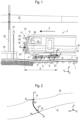
- a rail vehicle 2 travels along the track 1 in a measuring direction 3 .
- a first measuring platform 5 is arranged on a front rail chassis 4 .
- This first measuring platform 5 expediently comprises a measuring frame 6 which is fastened to axles of the rail undercarriage 4 designed as a bogie.
- two position measuring devices 8 can be attached to the first measuring platform 5 for each rail 7 of the track 1 in order to detect movements of the first measuring platform 5 relative to the rails 7 .
- the respective position measuring device 8 includes, for example, a laser directed onto the rail 7 and a camera for detecting the laser projection.
- a first inertial measuring system 9 is set up on the first measuring platform 5 and records a first spatial curve 10 in relation to an inertial reference system x i , y i , z i .
- This first spatial curve 10 runs at a known distance parallel to a track axis 11 which runs symmetrically between the inner edges of the two rails 8 . A relative course of the track is thus determined.
- a coordinate system x g , y g , z g of the first measurement platform 5 is along this first space curve 10 moves. If necessary, the position measuring devices 8 are used to record the spatial curve for each rail 7 of the track 1.
- a second measuring platform 14 is arranged on a front side 13 of the rail vehicle 2 and is rigidly connected to a vehicle frame 12 .
- a second inertial measuring system 15 for detecting a second space curve 16 is attached to this second measuring platform 14 .
- a coordinate system x s , y s , z s of the second measurement platform 14 is moved along the second space curve 16 .
- each inertial measurement system 9, 15 three accelerometers and three yaw rate sensors are orthogonally combined.
- the relative position to the inertial reference system x is determined from the measured rotation rates of the respective inertial measuring system 9, 15, which are given in the associated co-moving coordinate system x g , y g , z g or x s , y s , z s i , y i , z i determined.
- the second measuring platform 14 serves as a carrier for a sensor device 17 which is designed to detect surface points P of a track section 18 to be checked.
- a sensor device 17 which is designed to detect surface points P of a track section 18 to be checked.
- the position of these objects 19-22 with respect to the coordinate system x s , y s is initially known , z s of the second measuring platform 14 can be determined.
- the sensor device 17 comprises a plurality of laser scanners, for example two 2D rotary scanners 23 and two 2D area scanners 24. With a known traveling speed of the rail vehicle 2, the measurement result is a three-dimensional point cloud. Their resolution can be varied by adjusting the scanning rates of the scanners 23, 24 and the driving speed. The coordinates of the individual surface points P of this point cloud are stored in a computer 25 with respect to the coordinate system x s , y s , z s of the second measurement platform 14 .
- the computer 25 is used to transform the coordinates of the surface points P from the coordinate system x s , y s , z s of the second measuring platform 14 moved with the sensor device 17 into the dem Track course following coordinate system x g , y g , z g of the first measuring platform 5 set up.
- a distance A between the two inertial measuring systems 9, 15 and the known driving speed are taken into account in order to synchronize the measured values of the two inertial measuring systems 9, 15.
- the coordinate transformation is in 2 illustrated.
- the coordinate system x s , y s , z s of the second measuring platform 14 is converted into the coordinate system x g , y g , z g of the first measuring platform 5 , with the inertial reference system x i , y i , z i serving as a common basis.
- Rail vehicle 2 is in 3 shown in a plan view and is located at the entrance to a curve in the track section 18.
- the 2D rotation scanner 23 scans the track 1 and the objects 19-22 located next to it in a helical manner during forward travel.
- the detected surface points P correspond to a profile of the track environment.
- This point cloud is supplemented with surface points P, which are recorded using the 2D area scanner 24 .
- the 2D area scanners 24 are aimed at areas that lie in a visual shadow of the 2D rotary scanner 23 .
- the two inertial measuring systems 9, 15 While driving through the curve, the two inertial measuring systems 9, 15 record different spatial curves 10, 16. In particular, the swinging out of the vehicle area in front of the front rail chassis 4 causes a significant deviation. In 4 the two space curves 10, 16 are superimposed as seen from above, with the origin points 0 g , 0 s of the two co-moving coordinate systems x g , y g , z g or x s , y s , z s being synchronized using the known distance A and the driving speed are.
- each detected surface point P are the coordinates x p s , y p s in the coordinate system x s , y s , z s of the second measuring platform 14 in coordinates xp, y p G in the coordinate system x g , y g , z g of the first measurement platform 5 can be transformed.
- the transformed coordinates x p G , y p G of the respective surface point P indicate the position with respect to the course of the track or the track axis 11.
- the results of the coordinate transformation are used in particular for checking clearances.
- those surface points P are taken into account whose x-coordinate (in the longitudinal direction of the track) in the co-moving coordinate system x g , y g , z g of the first measuring platform 5 is equal to zero.
- the y-coordinates and z-coordinates of these surface points P are compared with limit values of a clearance gauge to be maintained.
- a clearance gauge is exceeded if a surface point P lies within the specified clearance gauge.
- the corresponding y-coordinate or z-coordinate is then less than a specified clearance gauge limit value.
- excess clearance gauges are displayed in a control center. Immediate display in an output device 26 of the rail vehicle 2 is also useful.
- the computer 25 is advantageously set up as an evaluation device for an online comparison of the coordinates of the surface points P with the clearance profile limit values.
- a path measuring device 27 or a GNSS receiver is arranged on the rail vehicle 2 .
- a fixed point measuring device attached to the rail vehicle 2 is useful in order to determine an absolute position relative to fixed points located next to the track 1 .
- a further advantage of the invention is given by the fact that the surface points P of the inner rail edges are also detected by means of the sensor device 17 . This allows the course of the track to be determined using the described coordinate transformation. This can be done offline, for example after a measurement run, in order to check the accuracy of the course of the track recorded by means of the first measurement platform 5 .
- the present invention thus includes redundant systems for determining the course of the track.
Landscapes
- Engineering & Computer Science (AREA)
- Mechanical Engineering (AREA)
- Architecture (AREA)
- Civil Engineering (AREA)
- Structural Engineering (AREA)
- Machines For Laying And Maintaining Railways (AREA)
- Length Measuring Devices With Unspecified Measuring Means (AREA)
- Length Measuring Devices By Optical Means (AREA)
- Electric Propulsion And Braking For Vehicles (AREA)
Claims (12)
- Véhicule ferroviaire (2) avec un châssis de véhicule (12) qui peut être déplacé sur des rails (7) d'une voie ferrée (1) de manière appuyée sur des mécanismes de roulement ferroviaires (4), comprenant une première plate-forme de mesure (5) avec un premier système de mesure d'inertie (9) pour la détection d'un tracé de voie et d'une première courbe spatiale (10), caractérisé en ce qu'une seconde plate-forme de mesure (14) qui comprend un second système de mesure d'inertie (15) pour la détection d'une seconde courbe spatiale (16) et au moins un dispositif de capteur (17) pour la détection de points superficiels (P) d'un parcours de voie (18) est disposée sur le véhicule ferroviaire (2), dans lequel le déplacement du dispositif de capteur (17) dans l'espace tridimensionnel est détecté avec le second système de mesure d'inertie (15).
- Véhicule ferroviaire (2) selon la revendication 1, caractérisé en ce qu'un ordinateur (25), auquel des données de mesure des systèmes de mesure d'inertie (9, 15) et du dispositif de capteur (17) sont acheminées et qui est configuré pour la transformation de coordonnées des points superficiels (P) d'un système de coordonnées (xs, ys, zs) entraîné avec le dispositif de capteur (17) de la seconde plate-forme de mesure (14) en un système de coordonnées (xg, ys, zg) suivant le tracé de voie de la première plate-forme de mesure (5), est disposé sur le véhicule ferroviaire (2).
- Véhicule ferroviaire (2) selon la revendication 2, caractérisé en ce qu'un dispositif d'évaluation, qui est configuré pour la comparaison des coordonnées des points superficiels (P) dans le système de coordonnées (xg, yg, zg) de la première plate-forme de mesure (5) à un profil d'espace libre prédéfini du parcours de voie (18), est disposé sur le véhicule ferroviaire (2).
- Véhicule ferroviaire (2) selon une des revendications 1 à 3, caractérisé en ce que la première plate-forme de mesure (5) est disposée sur un des mécanismes de roulement ferroviaires (4).
- Véhicule ferroviaire (2) selon la revendication 4, caractérisé en ce que la première plate-forme de mesure (5) comprend un cadre de mesure (6) disposé sur des essieux du mécanisme de roulement ferroviaire (4), sur lequel le premier système de mesure d'inertie (9) est disposé.
- Véhicule ferroviaire (2) selon la revendication 5, caractérisé en ce qu'au moins deux dispositifs de mesure de position (8) pour la détermination de la position du cadre de mesure (6) par rapport aux rails (7) de la voie ferrée (1) sont disposés sur le cadre de mesure (6).
- Véhicule ferroviaire (2) selon une des revendications 1 à 6, caractérisé en ce que la seconde plate-forme de mesure (14) est disposée sur un côté frontal (13) du véhicule ferroviaire (2).
- Véhicule ferroviaire (2) selon une des revendications 1 à 7, caractérisé en ce que le dispositif de capteur (17) comprend un scanner laser (23, 24) pour la détection des points superficiels (P) en tant que nuage de points.
- Procédé de mesure d'un parcours de voie (18) au moyen d'un véhicule ferroviaire (2) selon une des revendications 1 à 8, caractérisé en ce que le tracé de voie est détecté, notamment en tant que tracé de déplacement d'un système de coordonnées (xg, yg, zg) de la première plate-forme de mesure (5), au moyen du premier système de mesure d'inertie (9) du tracé de voie, qu'un tracé de déplacement du dispositif de capteur (17) est détecté, notamment en tant que tracé de déplacement d'un système de coordonnées (xs, ys, zs) de la seconde plate-forme de mesure (14), au moyen du second système de mesure d'inertie (15), et que des points superficiels (P) du parcours de voie (17) sont détectés au moyen du dispositif de capteur (17).
- Procédé selon la revendication 9, caractérisé en ce que des coordonnées des points superficiels (P) sont transformées d'un système de coordonnées (xs, ys, zs) entraîné avec le dispositif de capteur (17) de la seconde plate-forme de mesure (14) en un système de coordonnées (xg, yg, zg) suivant le tracé de voie de la première plate-forme de mesure (5).
- Procédé selon la revendication 10, caractérisé en ce que des coordonnées des points superficiels (P) dans le système de coordonnées (xg, yg, zg) de la première plate-forme de mesure (5) sont comparées à un profil d'espace libre du parcours de voie (17).
- Procédé selon la revendication 11, caractérisé en ce qu'un dépassement de profil d'espace libre d'un point superficiel (P) est affiché dans un dispositif de sortie (26).
Applications Claiming Priority (2)
| Application Number | Priority Date | Filing Date | Title |
|---|---|---|---|
| ATA29/2018A AT520526B1 (de) | 2018-02-02 | 2018-02-02 | Schienenfahrzeug und Verfahren zum Vermessen einer Gleisstrecke |
| PCT/EP2019/050013 WO2019149456A1 (fr) | 2018-02-02 | 2019-01-02 | Véhicule ferroviaire et procédé de mesure d'une voie ferrée |
Publications (2)
| Publication Number | Publication Date |
|---|---|
| EP3746346A1 EP3746346A1 (fr) | 2020-12-09 |
| EP3746346B1 true EP3746346B1 (fr) | 2023-03-08 |
Family
ID=65010770
Family Applications (1)
| Application Number | Title | Priority Date | Filing Date |
|---|---|---|---|
| EP19700195.1A Active EP3746346B1 (fr) | 2018-02-02 | 2019-01-02 | Véhicule ferroviaire et procédé de mesure d'une voie ferrée |
Country Status (12)
| Country | Link |
|---|---|
| US (1) | US11912317B2 (fr) |
| EP (1) | EP3746346B1 (fr) |
| JP (1) | JP7247206B2 (fr) |
| KR (1) | KR20200111673A (fr) |
| CN (1) | CN111587202B (fr) |
| AT (1) | AT520526B1 (fr) |
| AU (1) | AU2019216197B2 (fr) |
| CA (1) | CA3087478A1 (fr) |
| EA (1) | EA039709B1 (fr) |
| ES (1) | ES2945477T3 (fr) |
| PL (1) | PL3746346T3 (fr) |
| WO (1) | WO2019149456A1 (fr) |
Families Citing this family (10)
| Publication number | Priority date | Publication date | Assignee | Title |
|---|---|---|---|---|
| AT519263B1 (de) * | 2016-12-19 | 2018-05-15 | Plasser & Theurer Export Von Bahnbaumaschinen Gmbh | Gleismessfahrzeug und Verfahren zum Erfassen einer Gleisgeometrie eines Gleises |
| AT520526B1 (de) * | 2018-02-02 | 2019-05-15 | Plasser & Theurer Export Von Bahnbaumaschinen Gmbh | Schienenfahrzeug und Verfahren zum Vermessen einer Gleisstrecke |
| US10807623B2 (en) | 2018-06-01 | 2020-10-20 | Tetra Tech, Inc. | Apparatus and method for gathering data from sensors oriented at an oblique angle relative to a railway track |
| US10908291B2 (en) | 2019-05-16 | 2021-02-02 | Tetra Tech, Inc. | System and method for generating and interpreting point clouds of a rail corridor along a survey path |
| CN114485511A (zh) * | 2020-10-27 | 2022-05-13 | 湖南中车智行科技有限公司 | 一种车辆限界宽度的测量方法及装置 |
| AT524207B1 (de) * | 2020-12-11 | 2022-04-15 | Siemens Mobility Austria Gmbh | Fahrwerk für ein Schienenfahrzeug |
| CN112678023B (zh) * | 2021-01-04 | 2022-08-30 | 天津路安工程咨询有限公司 | 一种轨道交通限界检测装置以及检测方法 |
| AT525018A1 (de) * | 2021-05-12 | 2022-11-15 | Plasser & Theurer Export Von Bahnbaumaschinen Gmbh | System und Verfahren zur Oberflächenerfassung einer Gleisstrecke |
| AT17971U1 (de) | 2022-05-24 | 2023-09-15 | Plasser & Theurer Export Von Bahnbaumaschinen Gmbh | Schienenfahrzeug und Verfahren zur Erfassung von Gleislagedaten |
| CN115451826B (zh) * | 2022-08-10 | 2023-05-30 | 西南交通大学 | 一种接触网几何参数的摄影测量方法及装置 |
Family Cites Families (34)
| Publication number | Priority date | Publication date | Assignee | Title |
|---|---|---|---|---|
| AT353487B (de) * | 1977-05-31 | 1979-11-12 | Plasser Bahnbaumasch Franz | Vermessungseinrichtung zur anzeige bzw. registrierung des profilverlaufes von tunnel- roehren, durchlaessen u.dgl. engstellen |
| US4654973A (en) * | 1985-10-21 | 1987-04-07 | Worthy James T | Railroad track gage |
| DE3913159A1 (de) * | 1989-04-21 | 1990-10-25 | Linsinger Maschinenbau Gmbh | Verfahren und vorrichtung zur messung von wellenfoermigen deformationen an wenigstens einer schienenoberseite (schienenlaufflaeche) eines schienenweges |
| AT402519B (de) * | 1990-02-06 | 1997-06-25 | Plasser Bahnbaumasch Franz | Kontinuierlich verfahrbare gleisbaumaschine zum verdichten der schotterbettung eines gleises |
| AT402953B (de) * | 1990-11-12 | 1997-10-27 | Plasser Bahnbaumasch Franz | Einrichtung zur berührungslosen spurweitenmessung von schienen |
| DE19532104C1 (de) | 1995-08-30 | 1997-01-16 | Daimler Benz Ag | Verfahren und Vorrichtung zur Bestimmung der Position wenigstens einer Stelle eines spurgeführten Fahrzeugs |
| DE19721915C1 (de) * | 1997-05-26 | 1998-12-10 | Stn Atlas Elektronik Gmbh | Verfahren und Vorrichtung zur Messung von Unebenheiten in einer Objektoberfläche |
| US7164975B2 (en) * | 1999-06-15 | 2007-01-16 | Andian Technologies Ltd. | Geometric track and track/vehicle analyzers and methods for controlling railroad systems |
| FR2798347B1 (fr) * | 1999-09-09 | 2001-11-30 | Matisa Materiel Ind Sa | Vehicule de mesure de l'etat geometrique d'une voie ferree |
| DE10220175C1 (de) * | 2002-05-06 | 2003-04-17 | Db Netz Ag | Messverfahren und Anordnung zum Erfassen der Nachgiebigkeit eines Gleises |
| GB2419759B (en) | 2003-07-11 | 2007-02-14 | Omnicom Engineering Ltd | A system of surveying and measurement |
| JP2005069700A (ja) | 2003-08-25 | 2005-03-17 | East Japan Railway Co | 三次元データ取得装置 |
| RU2256575C1 (ru) * | 2003-11-04 | 2005-07-20 | Общество с ограниченной ответственностью "Научно-производственная фирма "Электронные системы управления и приборы" (ООО "НПФ "ЭСУП") | Способ измерения геометрии рельсового пути и устройство для его осуществления |
| US7937246B2 (en) * | 2007-09-07 | 2011-05-03 | Board Of Regents Of The University Of Nebraska | Vertical track modulus trending |
| AT505029B1 (de) | 2007-07-31 | 2008-10-15 | Plasser Bahnbaumasch Franz | Verfahren zur vermessung einer gleislage |
| US8412393B2 (en) * | 2008-07-01 | 2013-04-02 | General Electric Company | Apparatus and method for monitoring of infrastructure condition |
| KR101026350B1 (ko) * | 2008-12-15 | 2011-04-04 | 한국철도기술연구원 | 관성센서를 이용한 궤도의 수평 틀림 측정 시스템 및 그 방법 |
| DE102008062143B3 (de) | 2008-12-16 | 2010-05-12 | Db Netz Ag | Verfahren zur Bestimmung der vertikalen Gleislage des schienengebundenen Eisenbahnverkehrs |
| JP2012208043A (ja) * | 2011-03-30 | 2012-10-25 | Railway Technical Research Institute | 鉄道構造物の振動特性同定方法および装置 |
| US9810533B2 (en) * | 2011-04-27 | 2017-11-07 | Trimble Inc. | Railway track monitoring |
| CN203020332U (zh) * | 2013-01-15 | 2013-06-26 | 萨伏威(西安)导航技术有限公司 | 一种卫星导航与惯性测量组合轨道测量系统 |
| JP2014194366A (ja) | 2013-03-28 | 2014-10-09 | Hitachi High-Technologies Corp | 軌道形状測定方法及び装置 |
| DE102013210361A1 (de) * | 2013-06-04 | 2014-12-04 | Siemens Aktiengesellschaft | Verfahren zur Ermittlung zumindest einer Geschwindigkeit bei einem Schienenfahrzeug |
| CN104420405A (zh) * | 2013-08-29 | 2015-03-18 | 中国铁道科学研究院铁道建筑研究所 | 一种测量铁路轨道静态几何参数的装置 |
| AT515208B1 (de) * | 2014-02-20 | 2015-07-15 | Plasser & Theurer Export Von Bahnbaumaschinen Gmbh | Gleisbaumaschine zur Durchführung von Gleislagekorrekturen und Verfahren |
| JP6293579B2 (ja) | 2014-06-02 | 2018-03-14 | 日本信号株式会社 | 軌道検査装置 |
| GB2542115B (en) * | 2015-09-03 | 2017-11-15 | Rail Vision Europe Ltd | Rail track asset survey system |
| AT518579B1 (de) * | 2016-04-15 | 2019-03-15 | Plasser & Theurer Export Von Bahnbaumaschinen Gmbh | Verfahren und Messsystem zum Erfassen eines Festpunktes neben einem Gleis |
| AT518692B1 (de) | 2016-06-13 | 2019-02-15 | Plasser & Theurer Exp Von Bahnbaumaschinen G M B H | Verfahren und System zur Instandhaltung eines Fahrwegs für Schienenfahrzeuge |
| US11014587B2 (en) * | 2017-03-27 | 2021-05-25 | Harsco Technologies LLC | Track geometry measurement system with inertial measurement |
| CN107097807A (zh) * | 2017-03-27 | 2017-08-29 | 北京交通大学 | 一种高速铁路轮轨动态接触状态的测定系统 |
| AT520526B1 (de) * | 2018-02-02 | 2019-05-15 | Plasser & Theurer Export Von Bahnbaumaschinen Gmbh | Schienenfahrzeug und Verfahren zum Vermessen einer Gleisstrecke |
| US11377130B2 (en) * | 2018-06-01 | 2022-07-05 | Tetra Tech, Inc. | Autonomous track assessment system |
| US10908291B2 (en) * | 2019-05-16 | 2021-02-02 | Tetra Tech, Inc. | System and method for generating and interpreting point clouds of a rail corridor along a survey path |
-
2018
- 2018-02-02 AT ATA29/2018A patent/AT520526B1/de active
-
2019
- 2019-01-02 WO PCT/EP2019/050013 patent/WO2019149456A1/fr unknown
- 2019-01-02 AU AU2019216197A patent/AU2019216197B2/en active Active
- 2019-01-02 EA EA202000159A patent/EA039709B1/ru unknown
- 2019-01-02 CA CA3087478A patent/CA3087478A1/fr active Pending
- 2019-01-02 JP JP2020541973A patent/JP7247206B2/ja active Active
- 2019-01-02 US US16/966,555 patent/US11912317B2/en active Active
- 2019-01-02 KR KR1020207017095A patent/KR20200111673A/ko not_active Application Discontinuation
- 2019-01-02 EP EP19700195.1A patent/EP3746346B1/fr active Active
- 2019-01-02 CN CN201980007338.0A patent/CN111587202B/zh active Active
- 2019-01-02 PL PL19700195.1T patent/PL3746346T3/pl unknown
- 2019-01-02 ES ES19700195T patent/ES2945477T3/es active Active
Also Published As
| Publication number | Publication date |
|---|---|
| KR20200111673A (ko) | 2020-09-29 |
| CN111587202B (zh) | 2023-07-18 |
| EA039709B1 (ru) | 2022-03-03 |
| US11912317B2 (en) | 2024-02-27 |
| AU2019216197B2 (en) | 2024-04-11 |
| EP3746346A1 (fr) | 2020-12-09 |
| ES2945477T3 (es) | 2023-07-03 |
| AU2019216197A1 (en) | 2020-07-02 |
| JP7247206B2 (ja) | 2023-03-28 |
| AT520526B1 (de) | 2019-05-15 |
| WO2019149456A1 (fr) | 2019-08-08 |
| US20200361502A1 (en) | 2020-11-19 |
| PL3746346T3 (pl) | 2023-07-10 |
| JP2021512813A (ja) | 2021-05-20 |
| EA202000159A1 (ru) | 2020-11-30 |
| CA3087478A1 (fr) | 2019-08-08 |
| CN111587202A (zh) | 2020-08-25 |
| BR112020012799A2 (pt) | 2020-11-24 |
| AT520526A4 (de) | 2019-05-15 |
Similar Documents
| Publication | Publication Date | Title |
|---|---|---|
| EP3746346B1 (fr) | Véhicule ferroviaire et procédé de mesure d'une voie ferrée | |
| DE10040139B4 (de) | Verfahren zur Messung von Schienenprofilen und Gleislagestörungen sowie Vorrichtung zur Durchführung des Verfahrens | |
| EP2793045B1 (fr) | Procédé de vérification d'un système de détection de l'environnement d'un véhicule | |
| EP3358079A1 (fr) | Procédé et dispositif d'optimisation d'une voie | |
| WO2007096273A1 (fr) | Procédé de surveillance assistée par ordinateur du fonctionnement d'un véhicule se déplaçant sur un parcours prédéterminé, en particulier d'un véhicule ferroviaire guidé sur rails | |
| EP3580393B1 (fr) | Procédé et véhicule de voie ferrée de détection sans contact de la géométrie d'une voie ferrée | |
| EP4021778B1 (fr) | Procédé et véhicule de mesure pour déterminer une position réelle d'une voie ferrée | |
| EP4214103A1 (fr) | Procédé et système pour déterminer un tracé théorique d'une voie en vue d'une correction de position | |
| DE102017222017A1 (de) | Verfahren und System zum Ermitteln und Bereitstellen eines Bodenprofils | |
| AT520291A4 (de) | Verfahren zur Ermittlung einer Ist-Lage von Schienen eines Gleises | |
| WO1994011705A1 (fr) | Procede et dispositif de saisie de donnees sur le profil et sur les rails | |
| DE102016224212A1 (de) | Automatisierte Freiraumerkennung mittels Differenzanalyse für Fahrzeuge | |
| WO2008122319A1 (fr) | Dispositif de mesure pour la détermination sans contact et continue du tracé et de l'assiette de voie de rails de chemins de fer | |
| EP3310637A1 (fr) | Dispositif de contrôle et procédé de contrôle d'un profil défini d'un convoi composé de véhicules, notamment de véhicules ferroviaires | |
| DE112020005320T5 (de) | Sensorausrichtungseinrichtung, fahrsteuersystem und korrekturbetragschätzverfahren | |
| AT524435B1 (de) | Verfahren und System zur Ermittlung von Korrekturwerten für eine Lagekorrektur eines Gleises | |
| DE212021000415U1 (de) | On-Board-Gleisprüfsystem | |
| DE102004055069A1 (de) | Mehrdimensionale Fahrbahnvermessung | |
| DE102004050690A1 (de) | Verfahren, Computer-Programm mit Programm-Code-Mitteln, Computer-Programm-Produkt und Gerät zur Modellierung der Umwelt eines autonomen mobilen Systems | |
| EP3990322B1 (fr) | Procédé d'étalonnage de l'orientation d'un capteur d'accélération disposé dans un véhicule | |
| DE102019110942A1 (de) | Automatische Steuerung einer Bahn eines Kraftfahrzeugs bezüglich einer Fahrspur | |
| DE102018213994A1 (de) | Verfahren und System zur Bestimmung der Bewegung eines Kraftfahrzeuges | |
| EP4105103A1 (fr) | Dispositif de détection d'environnement à ajustement automatique pour véhicules ferroviaires | |
| DE102022205527A1 (de) | Validierung einer Sensoreinheit eines Schienenfahrzeugs zur Objektlokalisierung | |
| EP3736195A1 (fr) | Procédé et dispositif de détermination des paramètres techniques dans des véhicules |
Legal Events
| Date | Code | Title | Description |
|---|---|---|---|
| STAA | Information on the status of an ep patent application or granted ep patent |
Free format text: STATUS: UNKNOWN |
|
| STAA | Information on the status of an ep patent application or granted ep patent |
Free format text: STATUS: THE INTERNATIONAL PUBLICATION HAS BEEN MADE |
|
| PUAI | Public reference made under article 153(3) epc to a published international application that has entered the european phase |
Free format text: ORIGINAL CODE: 0009012 |
|
| STAA | Information on the status of an ep patent application or granted ep patent |
Free format text: STATUS: REQUEST FOR EXAMINATION WAS MADE |
|
| 17P | Request for examination filed |
Effective date: 20200902 |
|
| AK | Designated contracting states |
Kind code of ref document: A1 Designated state(s): AL AT BE BG CH CY CZ DE DK EE ES FI FR GB GR HR HU IE IS IT LI LT LU LV MC MK MT NL NO PL PT RO RS SE SI SK SM TR |
|
| AX | Request for extension of the european patent |
Extension state: BA ME |
|
| DAV | Request for validation of the european patent (deleted) | ||
| DAX | Request for extension of the european patent (deleted) | ||
| GRAP | Despatch of communication of intention to grant a patent |
Free format text: ORIGINAL CODE: EPIDOSNIGR1 |
|
| STAA | Information on the status of an ep patent application or granted ep patent |
Free format text: STATUS: GRANT OF PATENT IS INTENDED |
|
| RIC1 | Information provided on ipc code assigned before grant |
Ipc: B61L 23/04 20060101ALI20220729BHEP Ipc: B61K 9/08 20060101AFI20220729BHEP |
|
| INTG | Intention to grant announced |
Effective date: 20220825 |
|
| GRAS | Grant fee paid |
Free format text: ORIGINAL CODE: EPIDOSNIGR3 |
|
| GRAA | (expected) grant |
Free format text: ORIGINAL CODE: 0009210 |
|
| STAA | Information on the status of an ep patent application or granted ep patent |
Free format text: STATUS: THE PATENT HAS BEEN GRANTED |
|
| AK | Designated contracting states |
Kind code of ref document: B1 Designated state(s): AL AT BE BG CH CY CZ DE DK EE ES FI FR GB GR HR HU IE IS IT LI LT LU LV MC MK MT NL NO PL PT RO RS SE SI SK SM TR |
|
| REG | Reference to a national code |
Ref country code: CH Ref legal event code: EP Ref country code: AT Ref legal event code: REF Ref document number: 1552411 Country of ref document: AT Kind code of ref document: T Effective date: 20230315 |
|
| REG | Reference to a national code |
Ref country code: IE Ref legal event code: FG4D Free format text: LANGUAGE OF EP DOCUMENT: GERMAN |
|
| REG | Reference to a national code |
Ref country code: DE Ref legal event code: R096 Ref document number: 502019007147 Country of ref document: DE |
|
| REG | Reference to a national code |
Ref country code: LT Ref legal event code: MG9D |
|
| REG | Reference to a national code |
Ref country code: ES Ref legal event code: FG2A Ref document number: 2945477 Country of ref document: ES Kind code of ref document: T3 Effective date: 20230703 |
|
| P01 | Opt-out of the competence of the unified patent court (upc) registered |
Effective date: 20230528 |
|
| REG | Reference to a national code |
Ref country code: NL Ref legal event code: MP Effective date: 20230308 |
|
| PG25 | Lapsed in a contracting state [announced via postgrant information from national office to epo] |
Ref country code: RS Free format text: LAPSE BECAUSE OF FAILURE TO SUBMIT A TRANSLATION OF THE DESCRIPTION OR TO PAY THE FEE WITHIN THE PRESCRIBED TIME-LIMIT Effective date: 20230308 Ref country code: NO Free format text: LAPSE BECAUSE OF FAILURE TO SUBMIT A TRANSLATION OF THE DESCRIPTION OR TO PAY THE FEE WITHIN THE PRESCRIBED TIME-LIMIT Effective date: 20230608 Ref country code: LV Free format text: LAPSE BECAUSE OF FAILURE TO SUBMIT A TRANSLATION OF THE DESCRIPTION OR TO PAY THE FEE WITHIN THE PRESCRIBED TIME-LIMIT Effective date: 20230308 Ref country code: LT Free format text: LAPSE BECAUSE OF FAILURE TO SUBMIT A TRANSLATION OF THE DESCRIPTION OR TO PAY THE FEE WITHIN THE PRESCRIBED TIME-LIMIT Effective date: 20230308 Ref country code: HR Free format text: LAPSE BECAUSE OF FAILURE TO SUBMIT A TRANSLATION OF THE DESCRIPTION OR TO PAY THE FEE WITHIN THE PRESCRIBED TIME-LIMIT Effective date: 20230308 |
|
| PG25 | Lapsed in a contracting state [announced via postgrant information from national office to epo] |
Ref country code: SE Free format text: LAPSE BECAUSE OF FAILURE TO SUBMIT A TRANSLATION OF THE DESCRIPTION OR TO PAY THE FEE WITHIN THE PRESCRIBED TIME-LIMIT Effective date: 20230308 Ref country code: NL Free format text: LAPSE BECAUSE OF FAILURE TO SUBMIT A TRANSLATION OF THE DESCRIPTION OR TO PAY THE FEE WITHIN THE PRESCRIBED TIME-LIMIT Effective date: 20230308 Ref country code: GR Free format text: LAPSE BECAUSE OF FAILURE TO SUBMIT A TRANSLATION OF THE DESCRIPTION OR TO PAY THE FEE WITHIN THE PRESCRIBED TIME-LIMIT Effective date: 20230609 Ref country code: FI Free format text: LAPSE BECAUSE OF FAILURE TO SUBMIT A TRANSLATION OF THE DESCRIPTION OR TO PAY THE FEE WITHIN THE PRESCRIBED TIME-LIMIT Effective date: 20230308 |
|
| PG25 | Lapsed in a contracting state [announced via postgrant information from national office to epo] |
Ref country code: SM Free format text: LAPSE BECAUSE OF FAILURE TO SUBMIT A TRANSLATION OF THE DESCRIPTION OR TO PAY THE FEE WITHIN THE PRESCRIBED TIME-LIMIT Effective date: 20230308 Ref country code: RO Free format text: LAPSE BECAUSE OF FAILURE TO SUBMIT A TRANSLATION OF THE DESCRIPTION OR TO PAY THE FEE WITHIN THE PRESCRIBED TIME-LIMIT Effective date: 20230308 Ref country code: PT Free format text: LAPSE BECAUSE OF FAILURE TO SUBMIT A TRANSLATION OF THE DESCRIPTION OR TO PAY THE FEE WITHIN THE PRESCRIBED TIME-LIMIT Effective date: 20230710 Ref country code: EE Free format text: LAPSE BECAUSE OF FAILURE TO SUBMIT A TRANSLATION OF THE DESCRIPTION OR TO PAY THE FEE WITHIN THE PRESCRIBED TIME-LIMIT Effective date: 20230308 Ref country code: CZ Free format text: LAPSE BECAUSE OF FAILURE TO SUBMIT A TRANSLATION OF THE DESCRIPTION OR TO PAY THE FEE WITHIN THE PRESCRIBED TIME-LIMIT Effective date: 20230308 |
|
| PG25 | Lapsed in a contracting state [announced via postgrant information from national office to epo] |
Ref country code: SK Free format text: LAPSE BECAUSE OF FAILURE TO SUBMIT A TRANSLATION OF THE DESCRIPTION OR TO PAY THE FEE WITHIN THE PRESCRIBED TIME-LIMIT Effective date: 20230308 Ref country code: IS Free format text: LAPSE BECAUSE OF FAILURE TO SUBMIT A TRANSLATION OF THE DESCRIPTION OR TO PAY THE FEE WITHIN THE PRESCRIBED TIME-LIMIT Effective date: 20230708 |
|
| REG | Reference to a national code |
Ref country code: DE Ref legal event code: R097 Ref document number: 502019007147 Country of ref document: DE |
|
| PLBE | No opposition filed within time limit |
Free format text: ORIGINAL CODE: 0009261 |
|
| STAA | Information on the status of an ep patent application or granted ep patent |
Free format text: STATUS: NO OPPOSITION FILED WITHIN TIME LIMIT |
|
| PGFP | Annual fee paid to national office [announced via postgrant information from national office to epo] |
Ref country code: GB Payment date: 20231222 Year of fee payment: 6 |
|
| PG25 | Lapsed in a contracting state [announced via postgrant information from national office to epo] |
Ref country code: SI Free format text: LAPSE BECAUSE OF FAILURE TO SUBMIT A TRANSLATION OF THE DESCRIPTION OR TO PAY THE FEE WITHIN THE PRESCRIBED TIME-LIMIT Effective date: 20230308 Ref country code: DK Free format text: LAPSE BECAUSE OF FAILURE TO SUBMIT A TRANSLATION OF THE DESCRIPTION OR TO PAY THE FEE WITHIN THE PRESCRIBED TIME-LIMIT Effective date: 20230308 |
|
| 26N | No opposition filed |
Effective date: 20231211 |
|
| PGFP | Annual fee paid to national office [announced via postgrant information from national office to epo] |
Ref country code: PL Payment date: 20231222 Year of fee payment: 6 |
|
| PGFP | Annual fee paid to national office [announced via postgrant information from national office to epo] |
Ref country code: ES Payment date: 20240207 Year of fee payment: 6 Ref country code: IE Payment date: 20240118 Year of fee payment: 6 |
|
| PGFP | Annual fee paid to national office [announced via postgrant information from national office to epo] |
Ref country code: AT Payment date: 20231215 Year of fee payment: 6 |
|
| PGFP | Annual fee paid to national office [announced via postgrant information from national office to epo] |
Ref country code: DE Payment date: 20240326 Year of fee payment: 6 Ref country code: CH Payment date: 20240202 Year of fee payment: 6 |
|
| PGFP | Annual fee paid to national office [announced via postgrant information from national office to epo] |
Ref country code: IT Payment date: 20240131 Year of fee payment: 6 Ref country code: FR Payment date: 20240123 Year of fee payment: 6 Ref country code: BE Payment date: 20240112 Year of fee payment: 6 |
|
| PG25 | Lapsed in a contracting state [announced via postgrant information from national office to epo] |
Ref country code: MC Free format text: LAPSE BECAUSE OF FAILURE TO SUBMIT A TRANSLATION OF THE DESCRIPTION OR TO PAY THE FEE WITHIN THE PRESCRIBED TIME-LIMIT Effective date: 20230308 |
|
| PG25 | Lapsed in a contracting state [announced via postgrant information from national office to epo] |
Ref country code: MC Free format text: LAPSE BECAUSE OF FAILURE TO SUBMIT A TRANSLATION OF THE DESCRIPTION OR TO PAY THE FEE WITHIN THE PRESCRIBED TIME-LIMIT Effective date: 20230308 |
|
| PG25 | Lapsed in a contracting state [announced via postgrant information from national office to epo] |
Ref country code: LU Free format text: LAPSE BECAUSE OF NON-PAYMENT OF DUE FEES Effective date: 20240102 |