EP3745896B1 - Vorrichtung zum anformen von schuheinlagen - Google Patents
Vorrichtung zum anformen von schuheinlagen Download PDFInfo
- Publication number
- EP3745896B1 EP3745896B1 EP19705699.7A EP19705699A EP3745896B1 EP 3745896 B1 EP3745896 B1 EP 3745896B1 EP 19705699 A EP19705699 A EP 19705699A EP 3745896 B1 EP3745896 B1 EP 3745896B1
- Authority
- EP
- European Patent Office
- Prior art keywords
- foot
- membrane
- moulding
- insole
- alignment aid
- Prior art date
- Legal status (The legal status is an assumption and is not a legal conclusion. Google has not performed a legal analysis and makes no representation as to the accuracy of the status listed.)
- Active
Links
Images

Classifications
-
- A—HUMAN NECESSITIES
- A43—FOOTWEAR
- A43B—CHARACTERISTIC FEATURES OF FOOTWEAR; PARTS OF FOOTWEAR
- A43B7/00—Footwear with health or hygienic arrangements
- A43B7/14—Footwear with health or hygienic arrangements with foot-supporting parts
- A43B7/28—Adapting the inner sole or the side of the upper of the shoe to the sole of the foot
-
- A—HUMAN NECESSITIES
- A43—FOOTWEAR
- A43D—MACHINES, TOOLS, EQUIPMENT OR METHODS FOR MANUFACTURING OR REPAIRING FOOTWEAR
- A43D1/00—Foot or last measuring devices; Measuring devices for shoe parts
- A43D1/02—Foot-measuring devices
-
- A—HUMAN NECESSITIES
- A43—FOOTWEAR
- A43B—CHARACTERISTIC FEATURES OF FOOTWEAR; PARTS OF FOOTWEAR
- A43B17/00—Insoles for insertion, e.g. footbeds or inlays, for attachment to the shoe after the upper has been joined
-
- A—HUMAN NECESSITIES
- A43—FOOTWEAR
- A43B—CHARACTERISTIC FEATURES OF FOOTWEAR; PARTS OF FOOTWEAR
- A43B7/00—Footwear with health or hygienic arrangements
- A43B7/14—Footwear with health or hygienic arrangements with foot-supporting parts
- A43B7/1405—Footwear with health or hygienic arrangements with foot-supporting parts with pads or holes on one or more locations, or having an anatomical or curved form
- A43B7/141—Footwear with health or hygienic arrangements with foot-supporting parts with pads or holes on one or more locations, or having an anatomical or curved form having an anatomical or curved form
-
- A—HUMAN NECESSITIES
- A43—FOOTWEAR
- A43D—MACHINES, TOOLS, EQUIPMENT OR METHODS FOR MANUFACTURING OR REPAIRING FOOTWEAR
- A43D1/00—Foot or last measuring devices; Measuring devices for shoe parts
- A43D1/02—Foot-measuring devices
- A43D1/022—Foot-measuring devices involving making footprints or permanent moulds of the foot
-
- A—HUMAN NECESSITIES
- A61—MEDICAL OR VETERINARY SCIENCE; HYGIENE
- A61F—FILTERS IMPLANTABLE INTO BLOOD VESSELS; PROSTHESES; DEVICES PROVIDING PATENCY TO, OR PREVENTING COLLAPSING OF, TUBULAR STRUCTURES OF THE BODY, e.g. STENTS; ORTHOPAEDIC, NURSING OR CONTRACEPTIVE DEVICES; FOMENTATION; TREATMENT OR PROTECTION OF EYES OR EARS; BANDAGES, DRESSINGS OR ABSORBENT PADS; FIRST-AID KITS
- A61F5/00—Orthopaedic methods or devices for non-surgical treatment of bones or joints; Nursing devices ; Anti-rape devices
- A61F5/01—Orthopaedic devices, e.g. long-term immobilising or pressure directing devices for treating broken or deformed bones such as splints, casts or braces
- A61F5/14—Special medical insertions for shoes for flat-feet, club-feet or the like
-
- B—PERFORMING OPERATIONS; TRANSPORTING
- B29—WORKING OF PLASTICS; WORKING OF SUBSTANCES IN A PLASTIC STATE IN GENERAL
- B29C—SHAPING OR JOINING OF PLASTICS; SHAPING OF MATERIAL IN A PLASTIC STATE, NOT OTHERWISE PROVIDED FOR; AFTER-TREATMENT OF THE SHAPED PRODUCTS, e.g. REPAIRING
- B29C43/00—Compression moulding, i.e. applying external pressure to flow the moulding material; Apparatus therefor
- B29C43/02—Compression moulding, i.e. applying external pressure to flow the moulding material; Apparatus therefor of articles of definite length, i.e. discrete articles
- B29C43/021—Compression moulding, i.e. applying external pressure to flow the moulding material; Apparatus therefor of articles of definite length, i.e. discrete articles characterised by the shape of the surface
-
- B—PERFORMING OPERATIONS; TRANSPORTING
- B29—WORKING OF PLASTICS; WORKING OF SUBSTANCES IN A PLASTIC STATE IN GENERAL
- B29D—PRODUCING PARTICULAR ARTICLES FROM PLASTICS OR FROM SUBSTANCES IN A PLASTIC STATE
- B29D35/00—Producing footwear
- B29D35/12—Producing parts thereof, e.g. soles, heels, uppers, by a moulding technique
- B29D35/122—Soles
-
- B—PERFORMING OPERATIONS; TRANSPORTING
- B29—WORKING OF PLASTICS; WORKING OF SUBSTANCES IN A PLASTIC STATE IN GENERAL
- B29D—PRODUCING PARTICULAR ARTICLES FROM PLASTICS OR FROM SUBSTANCES IN A PLASTIC STATE
- B29D35/00—Producing footwear
- B29D35/12—Producing parts thereof, e.g. soles, heels, uppers, by a moulding technique
- B29D35/128—Moulds or apparatus therefor
Definitions
- the invention relates to a device for molding shoe inserts onto a foot, with a mold cushion which is arranged on a support and forms a foot-receiving area.
- the cushion has a layered structure, with the layer facing the wearer consisting of a foam material and the second layer detachably arranged thereon, forming a foot-receiving area, consisting of a gel-like material.
- a preheated, thermoformable shoe insert is placed in the foot receiving area and a foot is then placed on the insert.
- the arch of the foot must at least partially penetrate the gel layer, which is only possible when greater forces are applied, so that molding can usually only be carried out using a weight force that can be applied while standing.
- the weight cannot be applied evenly to the entire foot, so that the gel layer, especially in the forefoot area, has to be pressed onto the foot using an attached grip tab until the insole has cooled down in the molded state and is therefore dimensionally stable.
- assistance is required when fitting and, due to the unstable, flexible gel layer, it is not possible to ensure that the user has a secure footing.
- the invention relates to an apparatus for molding shoe inserts as specified in independent claim 1 and to a method for molding shoe inserts with such an apparatus according to claim 6. Preferred embodiments of the invention are disclosed in the dependent claims.
- the invention is therefore based on the object of designing a device of the type described at the outset in such a way that shoe inserts can be molded on without assistance and independently of whether the user is standing or sitting.
- the molded cushion has a flexurally elastic membrane for supporting the shoe insert, which is connected to a support surface of the wearer via a foot support point fixation, and that between the membrane and the support surface there is a filling area for a fluid for molding the shoe insert to the foot is provided.
- the user's foot can remain in a resting position during fitting because the shoe insert is molded onto the foot independently of the weight applied by the user by filling the filling area with a fluid via the membrane.
- the fitting pressure can be regulated via the filling quantity or the fluid pressure within the filling area, with advantageous fitting conditions resulting when the fitting pressure is selected in such a way that on the one hand it allows deformation of the shoe insert and on the other hand the weight of the user's foot in a sitting position does not or only slightly exceeds it.
- the flexible membrane is connected to a support surface of the wearer via a foot support point fixation, so that the membrane in the area of the foot support point fixation is not lifted by the fluid can be, so that there is a defined contact area between the shoe insert and the foot.
- the foot support point fixation is advantageously located in the heel section of the foot receiving area, because the user's heel allows for particularly simple positioning. However, it is also conceivable, for example, to arrange the foot support point fixation in the ball section.
- an alignment aid be provided in the foot-receiving area of the molded cushion, which has a flexible Has border area. While the alignment aid can already be partially adapted to a normal foot shape in order to specify the position of the shoe insert and the foot, the flexible edge area of the alignment aid enables reliable adaptation depending on the actual shape and size of the user's foot.
- the alignment aid can be connected to the support surface of the wearer via the foot support point fixation. If the alignment aid is arranged above the membrane, the filling area for the fluid, like the membrane, only has to be penetrated once, namely through the foot support point fixation. In this case, the foot support point fixation and the membrane must of course be fluid-tight.
- the alignment aid can be arranged within the filling area so that the shoe insert can also be completely molded to the shape of the user's foot in the area of the preformed alignment aid. This means that when the filling area is filled with a fluid, the alignment aid remains in its position relative to the support surface or to the wearer, while the membrane for shaping the shoe insert is lifted from the alignment aid and conforms to the shape of the user's foot. When the fluid is emptied from the filling area, this feature also enables the edge area of the alignment aid to be returned to a starting position, which ensures reliable, long-term operation, particularly when the device according to the invention is used frequently.
- the shoe insole is shaped in the toe area, which is undesirable per se.
- the device has a slide for limiting the stop of the membrane in the ball-side foot receiving area. This results in an additional stable support point for the user's foot in the toe area, which further promotes the positioning of the foot.
- the invention also relates to a method for molding shoe insoles using a device according to one of the preceding claims, the shoe insole being arranged on the membrane when the filling area is largely empty and the filling area being filled with a fluid after the foot has been placed on the shoe insole, and that after the shoe insert has been molded on, the filling area is emptied to release the foot and the shoe insert.
- the alignment aid protrudes through the membrane and facilitates the positioning of the insole and the foot.
- the fluid used can be air or water, for example, the former allowing easy handling of the device according to the invention.
- a device has a molded cushion 3 which is arranged on a support 1 and forms a foot-receiving area 2 , which cushion has a flexible membrane 4 for supporting a shoe insert 5 .
- the membrane 4 is also connected to a support surface 7 of the carrier 1 via a foot support point fixation 6 .
- a filling area 8 for a fluid for molding the shoe insert 5 onto the foot 9 of a user.
- the filling area can be formed, for example, in that the membrane forms a fillable bladder or in that the membrane forms a fluid-tight seal with the carrier.
- the shoe insert 5 is first arranged in the foot receiving area 2 of the membrane 4 and then the user's foot 9 is placed on the shoe insert 5 . Subsequently, the membrane 4 is subjected to pressure in that the initially empty filling area 8 is filled with a fluid. As a result of the expansion of the membrane 4, it presses the moldable shoe insert 5 onto the foot 9 in a shaping manner. After the shoe insert 5 has been adjusted to the foot 9 of the user in this way, the filling area 8 is emptied again so that the foot 9 and the molded shoe insert 5 can be removed from the foot receiving area 2 .
- an alignment aid 10 can be provided in the foot receiving area 2 of the molded cushion 3 according to one embodiment of the device according to the invention.
- the alignment aid 10 can have a flexible edge region 11 so that the shoe insert 5 can nestle against the foot 9 of the user as a result of the pressure being applied to the membrane 4.
- the alignment aid 10 is connected to the bearing surface 7 of the wearer 1 via the foot bearing point fixation 6 .
- the foot support point fixation 6 can be screwed to the carrier 1 .
- the alignment aid 10 can be arranged within the filling area 8 so that the membrane 4 can nestle completely against the foot 9 of the user when it is molded on. This results in the further advantage that when the filling area 8 is emptied, the membrane 4 can nestle against the alignment aid 10 in such a way that the positioning of the shoe insert 5 and the foot 9 can be carried out even more easily.
- the device can also have a slide 12 for limiting the stop of the membrane 4 in the ball-side foot receiving area 2 .
- the slider 12 can expediently be displaced in the longitudinal direction of the wearer before a molding process in such a way that the length of the foot receiving area 2 can be adjusted and consequently the section of the shoe insert 5 to be molded on can be fixed.
- thermoformable shoe inserts 5 are used, it can be provided according to the invention that the fluid flowing into the filling area 8 is cooled so that the thermoformable shoe inserts 5 can harden more quickly in a dimensionally stable state after they have been molded onto the foot 9 .
- a flexible buffer element 13 for example made of a foam material, can be provided, which is arranged between the alignment aid 10 and the bearing surface 7 of the carrier 1, in order to provide a more pleasant, tactile perception of the user when positioning the foot 9 largely empty filling area 8 to allow.
Landscapes
- Health & Medical Sciences (AREA)
- Life Sciences & Earth Sciences (AREA)
- Public Health (AREA)
- General Health & Medical Sciences (AREA)
- Engineering & Computer Science (AREA)
- Biophysics (AREA)
- Epidemiology (AREA)
- Mechanical Engineering (AREA)
- Orthopedic Medicine & Surgery (AREA)
- Vascular Medicine (AREA)
- Animal Behavior & Ethology (AREA)
- Heart & Thoracic Surgery (AREA)
- Biomedical Technology (AREA)
- Veterinary Medicine (AREA)
- Nursing (AREA)
- Footwear And Its Accessory, Manufacturing Method And Apparatuses (AREA)
Description
- Die Erfindung bezieht sich auf eine Vorrichtung zum Anformen von Schuheinlagen an einen Fuß mit einem auf einem Träger angeordneten, einen Fußaufnahmebereich bildenden Formkissen.
- Es sind Vorrichtungen zum Anformen von Schuheinlagen bekannt
- (
US 20160288440 A1 ,FR 2 682 028 A1 - Die Erfindung betrifft eine Vorrichtung zum Anformen von Schuheinlagen, wie er im unabhängigen Anspruch 1 angegeben ist, und ein Verfahren zum Anformen von Schuheinlagen mit einer solchen Vorrichtung nach Anspruch 6. Bevorzugte Ausführungsformen der Erfindung sind in den abhängigen Ansprüchen offenbart.
- Der Erfindung liegt somit die Aufgabe zugrunde, eine Vorrichtung der eingangs geschilderten Art so auszugestalten, dass ein Anformen von Schuheinlagen ohne Hilfestellung und unabhängig von einer Steh- oder Sitzposition des Benützers erfolgen kann.
- Die Erfindung löst die gestellte Aufgabe dadurch, dass das Formkissen eine biegeelastische Membran zur Auflage der Schuheinlage aufweist, die über eine Fußauflagepunktfixierung mit einer Auflagefläche des Trägers verbunden ist und dass zwischen der Membran und der Auflagefläche ein Füllbereich für ein Fluid zum Anformen der Schuheinlage an den Fuß vorgesehen ist. Zufolge der erfindungsgemäßen Merkmale kann der Fuß des Benützers beim Anformen in einer Ruhestellung verbleiben, weil die Schuheinlage unabhängig von der vom Benützer aufgebrachten Gewichtskraft durch Füllen des Füllbereichs mit einem Fluid über die Membran an den Fuß angeformt wird. Der Anformdruck kann dabei über die Füllmenge bzw. den Fluiddruck innerhalb des Füllbereiches reguliert werden, wobei sich vorteilhafte Anformbedingungen ergeben, wenn der Anformdruck so gewählt wird, dass er einerseits eine Verformung der Schuheinlage ermöglicht und andererseits die Gewichtskraft des Fußes des Benützers in sitzender Position nicht oder nur geringfügig übersteigt. Um dabei dennoch eine zuverlässige Positionierung der Schuheinlage und des Fußes zueinander zu ermöglichen und insbesondere ein Wegrutschen des Fußes zu vermeiden, ist erfindungsgemäß die biegeelastische Membran über eine Fußauflagepunktfixierung mit einer Auflagefläche des Trägers verbunden, sodass die Membran im Bereich der Fußauflagepunktfixierung nicht durch das Fluid angehoben werden kann, sodass ein definierter Auflagebereich zwischen der Schuheinlage und dem Fuß gegeben ist. Vorteilhafterweise befindet sich die Fußauflagepunktfixierung im Fersenabschnitt des Fußaufnahmebereiches, weil die Ferse des Benützers eine besonders einfache Positionierung erlaubt. Es ist aber beispielsweise auch denkbar, die Fußauflagepunktfixierung im Ballenabschnitt anzuordnen.
- Um die Ausrichtung der anzuformenden Schuheinlage und des Fußes des Benützers zueinander zu erleichtern, wird vorgeschlagen, dass im Fußaufnahmebereich des Formkissens eine Ausrichtungshilfe vorgesehen ist, die einen biegeelastischen Randbereich aufweist. Während die Ausrichtungshilfe bereits teilweise an eine gewöhnliche Fußform angepasst sein kann, um die Position der Schuheinlage und des Fußes vorzugeben, ermöglicht der biegeelastische Randbereich der Ausrichtungshilfe eine zuverlässige Anformung abhängig von der tatsächlichen Form und der Größe des Fußes des Benützers.
- Um besonders einfache Konstruktionsbedingungen zu schaffen, kann die Ausrichtungshilfe über die Fußauflagepunktfixierung mit der Auflagefläche des Trägers verbunden sein. Wird die Ausrichtungshilfe oberhalb der Membran angeordnet, so muss der Füllbereich für das Fluid genauso wie die Membran nur einmal, nämlich durch die Fußauflagepunktfixierung, durchsetzt werden. Die Fußauflagepunktfixierung und die Membran müssen in diesem Fall selbstverständlich fluiddicht abschließen.
- Damit auch im Bereich der vorgeformten Ausrichtungshilfe eine vollständige Anformung der Schuheinlage an die Fußform des Benützers erreicht werden kann, kann die Ausrichtungshilfe innerhalb des Füllbereiches angeordnet sein. Dies bedeutet, dass die Ausrichtungshilfe beim Füllen des Füllbereiches mit einem Fluid in ihrer relativen Lage zur Auflagefläche bzw. zum Träger bleibt, während sich die Membran zur Anformung der Schuheinlage von der Ausrichtungshilfe abhebt und an die Fußform des Benützers anschmiegt. Beim einem Entleeren des Fluides aus dem Füllbereich ermöglicht dieses Merkmal auch eine Rückstellung des Randbereiches der Ausrichtungshilfe in eine Ausgangslage, was insbesondere bei einer häufigen Verwendung der erfindungsgemäßen Vorrichtung einen zuverlässigen, langfristigen Betrieb sicherstellt.
- Je nach Größe des Fußes des Benützers kann sich das Problem ergeben, dass auch eine an sich unerwünschte Anformung der Schuheinlage im Zehenbereich erfolgt. Um dies zu verhindern, wird vorgeschlagen, dass die Vorrichtung einen Schieber zur Anschlagsbegrenzung der Membran im ballenseitigen Fußaufnahmebereich aufweist. Dadurch ergibt sich im Zehenbereich ein zusätzlicher stabiler Auflagepunkt für den Fuß des Benützers, was die Positionierung des Fußes weiter begünstigt.
- Die Erfindung bezieht sich auch auf ein Verfahren zum Anformen von Schuheinlagen mit einer Vorrichtung nach einem der vorangegangenen Ansprüche, wobei die Schuheinlage bei weitgehend leerem Füllbereich auf der Membran angeordnet und nach dem Aufsetzen des Fußes auf die Schuheinlage der Füllbereich mit einem Fluid gefüllt wird, und dass nach dem Anformen der Schuheinlage der Füllbereich zur Freigabe des Fußes und der Schuheinlage entleert wird. Im weitgehend entleerten Zustand des Füllbereiches tritt somit die Ausrichtungshilfe durch die Membran hervor und erleichtert die Positionierung der Schuheinlage sowie des Fußes. Besonders vorteilhafte Bedingungen ergeben sich in Verbindung mit thermoformbaren Schuheinlagen, wenn das verwendete Fluid gekühlt wird, weil es dadurch zu einem rascheren Abkühlen der vorgewärmten Schuheinlage und damit zu einer frühzeitigeren Formstabilität kommt. Bei dem eingesetzten Fluid kann es sich beispielsweise um Luft oder Wasser handeln, wobei ersteres eine einfache Handhabung der erfindungsgemäßen Vorrichtung erlaubt.
- In der Zeichnung ist der Erfindungsgegenstand beispielsweise dargestellt. Es zeigen
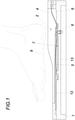
- Fig. 1
- eine erfindungsgemäße Vorrichtung in einer ersten Ausführungsform in einem schematischen Schnitt bei entleertem Füllbereich,
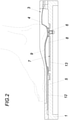
- Fig. 2
- eine der
Fig. 1 entsprechende Darstellung bei gefülltem Füllbereich und aufgesetztem Fuß eines Anwenders, - Fig. 3
- eine erfindungsgemäße Vorrichtung in einer zweiten Ausführungsform in einer der
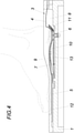
Fig. 1 entsprechenden Darstellung und - Fig. 4
- eine der
Fig. 3 entsprechende Darstellung bei gefülltem Füllbereich und aufgesetztem Fuß eines Anwenders. - Eine erfindungsgemäße Vorrichtung weist ein auf einem Träger 1 angeordnetes, einen Fußaufnahmebereich 2 bildendes Formkissen 3 auf, das eine biegeelastische Membran 4 zur Auflage einer Schuheinlage 5 aufweist. Die Membran 4 ist zudem über eine Fußauflagepunktfixierung 6 mit einer Auflagefläche 7 des Trägers 1 verbunden. Zwischen der Membran 4 und der Auflagefläche 7 des Trägers 1 ist ein Füllbereich 8 für ein Fluid zum Anformen der Schuheinlage 5 an den Fuß 9 eines Benützers vorgesehen. Der Füllbereich kann beispielsweise dadurch gebildet werden, dass die Membran eine füllbare Blase bildet oder dass die Membran fluiddicht mit dem Träger abschließt.
- Bei einem Anformvorgang wird zuerst die Schuheinlage 5 im Fußaufnahmebereich 2 der Membran 4 angeordnet und sodann der Fuß 9 des Benützers auf die Schuheinlage 5 aufgesetzt. In weiterer Folge wird die Membran 4 mit Druck beaufschlagt, in dem der zunächst leere Füllbereich 8 mit einem Fluid gefüllt wird. Zufolge der Expansion der Membran 4 drückt diese die formbare Schuheinlage 5 formgebend an den Fuß 9 an. Nachdem die Schuheinlage 5 auf diese Weise an den Fuß 9 des Benützers angepasst worden ist, wird der Füllbereich 8 wieder entleert, sodass der Fuß 9 sowie die angeformte Schuheinlage 5 aus dem Fußaufnahmebereich 2 entfernt werden können.
- Um die Ausrichtung der Schuheinlage 5 und des Fußes 9 zueinander zu vereinfachen, kann gemäß einer Ausführungsform der erfindungsgemäßen Vorrichtung eine Ausrichtungshilfe 10 im Fußaufnahmebereich 2 des Formkissens 3 vorgesehen sein. Um trotz einer konturgebenden Ausgestaltung der Ausrichtungshilfe 10 einen Anformvorgang nicht zu behindern, kann die Ausrichtungshilfe 10 einen biegeelastischen Randbereich 11 aufweisen, sodass sich die Schuheinlage 5 zufolge der Druckbeaufschlagung der Membran 4 an den Fuß 9 des Benützers anschmiegen kann.
- Um einfache Konstruktionsbedingungen zu schaffen, kann es gemäß einer Ausführungsform vorgesehen sein, dass die Ausrichtungshilfe 10 über die Fußauflagepunktfixierung 6 mit der Auflagefläche 7 des Trägers 1 verbunden ist. Beispielsweise kann die Fußauflagepunktfixierung 6 mit dem Träger 1 verschraubt sein.
- Damit sich die Membran 4 beim Anformen vollständig an den Fuß 9 des Benützers anschmiegen kann, kann die Ausrichtungshilfe 10 innerhalb des Füllbereiches 8 angeordnet sein. Dadurch ergibt sich der weitere Vorteil, dass sich beim Entleeren des Füllbereiches 8 die Membran 4 so an die Ausrichtungshilfe 10 anschmiegen kann, dass die Positionierung von Schuheinlage 5 und Fuß 9 noch einfacher vorgenommen werden kann.
- Um eine unerwünschte Anformung der Schuheinlage 5 bei unterschiedlichen Schuhgrößen beispielsweise an den Zehenbereich zu vermeiden, kann die Vorrichtung zudem einen Schieber 12 zur Anschlagsbegrenzung der Membran 4 im ballenseitigen Fußaufnahmebereich 2 aufweisen. Dabei kann der Schieber 12 zweckmäßigerweise vor einem Anformvorgang in Trägerlängsrichtung so verschoben werden, dass die Länge des Fußaufnahmebereiches 2 eingestellt und folglich der anzuformende Abschnitt der Schuheinlage 5 festgelegt werden kann.
- Werden thermoformbare Schuheinlagen 5 eingesetzt, kann erfindungsgemäß vorgesehen sein, dass das in den Füllbereich 8 einströmende Fluid gekühlt wird, sodass die thermoformbaren Schuheinlagen 5 schneller in einem formstabilen Zustand aushärten können, nachdem sie an den Fuß 9 angeformt worden sind.
- Zudem kann gemäß einer Ausführungsform der erfindungsgemäßen Vorrichtung ein nachgiebiges Pufferelement 13, beispielsweise aus einem Schaumstoff, vorgesehen sein, das zwischen der Ausrichtungshilfe 10 und der Auflagefläche 7 des Trägers 1 angeordnet ist, um eine angenehmere, taktile Wahrnehmung des Benützers beim Positioniervorgang des Fußes 9 bei weitgehend leerem Füllbereich 8 zu ermöglichen.
Claims (6)
- Vorrichtung zum Anformen von Schuheinlagen (5) an einen Fuß (9) mit einem auf einem Träger (1) angeordneten, einen Fußaufnahmebereich (2) bildenden Formkissen (3), das eine biegeelastische Membran (4) zur Auflage der Schuheinlage (5) aufweist, wobei die Membran (4) über eine Fußauflagepunktfixierung (6) mit einer Auflagefläche (7) des Trägers (1) verbunden ist und dass zwischen der Membran (4) und der Auflagefläche (7) ein Füllbereich (8) für ein Fluid zum Anformen der Schuheinlage (5) an den Fuß (9) vorgesehen ist.
- Vorrichtung nach Anspruch 1, dadurch gekennzeichnet, dass im Fußaufnahmebereich (2) des Formkissens (3) eine Ausrichtungshilfe (10) vorgesehen ist, die einen biegeelastischen Randbereich (11) aufweist.
- Vorrichtung nach Anspruch 2, dadurch gekennzeichnet, dass die Ausrichtungshilfe (10) über die Fußauflagepunktfixierung (6) mit der Auflagefläche (7) des Trägers (1) verbunden ist.
- Vorrichtung nach einem der Ansprüche 2 bis 3, dadurch gekennzeichnet, dass die Ausrichtungshilfe (10) innerhalb des Füllbereiches (8) angeordnet ist.
- Vorrichtung nach einem der Ansprüche 1 bis 4, dadurch gekennzeichnet, dass die Vorrichtung einen Schieber (12) zur Anschlagsbegrenzung der Membran (4) im ballenseitigen Fußaufnahmebereich (2) aufweist.
- Verfahren zum Anformen von Schuheinlagen (5) mit einer Vorrichtung nach einem der vorangegangenen Ansprüche, wobei die Schuheinlage (5) bei weitgehend leerem Füllbereich (8) auf der Membran (4) angeordnet und nach dem Aufsetzen des Fußes (9) auf die Schuheinlage (5) der Füllbereich (8) mit einem Fluid gefüllt wird, und dass nach dem Anformen der Schuheinlage (5) der Füllbereich (8) zur Freigabe des Fußes (9) und der Schuheinlage (5) entleert wird.
Applications Claiming Priority (2)
| Application Number | Priority Date | Filing Date | Title |
|---|---|---|---|
| ATA50080/2018A AT520635B1 (de) | 2018-01-30 | 2018-01-30 | Vorrichtung zum Anformen von Schuheinlagen |
| PCT/AT2019/050003 WO2019148217A1 (de) | 2018-01-30 | 2019-01-10 | Vorrichtung zum anformen von schuheinlagen |
Publications (2)
| Publication Number | Publication Date |
|---|---|
| EP3745896A1 EP3745896A1 (de) | 2020-12-09 |
| EP3745896B1 true EP3745896B1 (de) | 2022-03-09 |
Family
ID=65443593
Family Applications (1)
| Application Number | Title | Priority Date | Filing Date |
|---|---|---|---|
| EP19705699.7A Active EP3745896B1 (de) | 2018-01-30 | 2019-01-10 | Vorrichtung zum anformen von schuheinlagen |
Country Status (4)
| Country | Link |
|---|---|
| US (1) | US20210137219A1 (de) |
| EP (1) | EP3745896B1 (de) |
| AT (1) | AT520635B1 (de) |
| WO (1) | WO2019148217A1 (de) |
Families Citing this family (1)
| Publication number | Priority date | Publication date | Assignee | Title |
|---|---|---|---|---|
| AT520635B1 (de) * | 2018-01-30 | 2019-06-15 | Wintersteiger Ag | Vorrichtung zum Anformen von Schuheinlagen |
Citations (1)
| Publication number | Priority date | Publication date | Assignee | Title |
|---|---|---|---|---|
| FR2682028A1 (fr) * | 1991-10-03 | 1993-04-09 | Leonard Michel | Procede, dispositif et appareillage pour l'obtention d'une empreinte de la surface d'un objet ou d'une partie du corps. |
Family Cites Families (10)
| Publication number | Priority date | Publication date | Assignee | Title |
|---|---|---|---|---|
| US1044171A (en) * | 1910-01-07 | 1912-11-12 | Wilhelminia M Guilford | Method of forming arch-supports or patterns therefor. |
| GB191225887A (en) * | 1912-11-11 | 1913-05-01 | William Charles Judso Guilford | Improvements in Methods of and Apparatus for Forming Foot-arch Supports. |
| US2082451A (en) * | 1935-05-27 | 1937-06-01 | Henry D Kivlahan | Plastic impression device |
| US2581489A (en) * | 1948-04-09 | 1952-01-08 | United Shoe Machinery Corp | Apparatus for making casts |
| US3458898A (en) * | 1965-01-28 | 1969-08-05 | Hermann Casparis | Apparatus for the production of orthopedic footrest or support |
| FR2621237A1 (fr) * | 1987-10-02 | 1989-04-07 | Poussou Alain | Procedes et dispositifs pour obtenir des empreintes corrigees des pieds afin de fabriquer des semelles correctrices |
| US5843483A (en) * | 1997-04-14 | 1998-12-01 | Gleason's Orthotics, Inc. | Apparatus for forming a foot orthotic |
| US20160288440A1 (en) * | 2015-03-31 | 2016-10-06 | Zero Gravity Inside, Inc. | Apparatus and method for custom molding an insole |
| DE102016100644B4 (de) * | 2016-01-15 | 2022-08-25 | Kühnreich Orthopädie GmbH | Vorrichtung zur Haltungskorrektur eines Fußes, sowie System und Verfahren zur Herstellung einer Fußbettung |
| AT520635B1 (de) * | 2018-01-30 | 2019-06-15 | Wintersteiger Ag | Vorrichtung zum Anformen von Schuheinlagen |
-
2018
- 2018-01-30 AT ATA50080/2018A patent/AT520635B1/de active
-
2019
- 2019-01-10 US US16/965,397 patent/US20210137219A1/en not_active Abandoned
- 2019-01-10 EP EP19705699.7A patent/EP3745896B1/de active Active
- 2019-01-10 WO PCT/AT2019/050003 patent/WO2019148217A1/de not_active Ceased
Patent Citations (1)
| Publication number | Priority date | Publication date | Assignee | Title |
|---|---|---|---|---|
| FR2682028A1 (fr) * | 1991-10-03 | 1993-04-09 | Leonard Michel | Procede, dispositif et appareillage pour l'obtention d'une empreinte de la surface d'un objet ou d'une partie du corps. |
Also Published As
| Publication number | Publication date |
|---|---|
| US20210137219A1 (en) | 2021-05-13 |
| WO2019148217A1 (de) | 2019-08-08 |
| AT520635B1 (de) | 2019-06-15 |
| EP3745896A1 (de) | 2020-12-09 |
| AT520635A4 (de) | 2019-06-15 |
Similar Documents
| Publication | Publication Date | Title |
|---|---|---|
| EP2074900B1 (de) | Austauschbarer Schuhabsatz, Schuhsohlenteil und Schuh | |
| EP2590527B1 (de) | Stützspange für Schuheinlagen | |
| DE3802035A1 (de) | Daempfungs- oder polsterkoerper zum einsatz in schuhen | |
| DE102020108911A1 (de) | Mittelsohlenstruktur für einen sportschuh | |
| EP2241207B1 (de) | Schaumkunststoff-Schuheinlegesohlen-Rohling | |
| EP1602294B1 (de) | Polyurethan-Schaum-Einlegesohle und Verfahren zu ihrer Herstellung | |
| AT520635B1 (de) | Vorrichtung zum Anformen von Schuheinlagen | |
| DE3527583A1 (de) | Fussbett sowie verfahren zu seiner herstellung | |
| DE102011117802A1 (de) | Schaftsystem für eine Prothese, Prothese und Herstellungsverfahren | |
| DE102010015145B4 (de) | Thermoplastisch verformbare Schuheinlegesohle | |
| DE69608103T2 (de) | Verfahren zum herstellen eines leistens | |
| WO2016146397A1 (de) | Schuh mit bandscheibenwerkstoff-dämpfungselement | |
| DE102010016010A1 (de) | Fräseinlagenrohling für die Herstellung einer orthopädischen Schuheinlage | |
| EP3989768A1 (de) | OPTISCHE FUßSOHLEN-SCANVORRICHTUNG UND SCHUHEINLAGEN-HERSTELLUNGSVORRICHTUNG MIT DERSELBEN, VERFAHREN ZUM ERMITTELN EINER DREIDIMENSIONALEN FORM EINER SCHUHEINLAGE UND VERFAHREN ZUM AUTOMATISCHEN HERSTELLEN EINER SCHUHEINLAGE | |
| DE102018129670A1 (de) | Verfahren zum Herstellen eines Einlagenbauteils | |
| DE102016100644B4 (de) | Vorrichtung zur Haltungskorrektur eines Fußes, sowie System und Verfahren zur Herstellung einer Fußbettung | |
| DE202016008126U1 (de) | Skischuh | |
| EP3742918B1 (de) | Sohlenelement mit definierten biegesteifigkeiten | |
| DE1874605U (de) | Mehrschichtiges fusspolster. | |
| DE202009010247U1 (de) | Laufsohle für Schuhe | |
| DE2601680A1 (de) | Verfahren und vorrichtung zum herstellen eines fussabdruckes aus gips | |
| DE102015206491A1 (de) | Mundeinsatz sowie Set umfassend mehrere Mundeinsätze | |
| EP3179875B1 (de) | Schuh | |
| DE102022113762A1 (de) | Hufschuh, verfahren zur herstellung eines hufschuhs und verwendung eines hufschuhs | |
| DE102014008513A1 (de) | Kontakteinlage für Fußsohlen |
Legal Events
| Date | Code | Title | Description |
|---|---|---|---|
| STAA | Information on the status of an ep patent application or granted ep patent |
Free format text: STATUS: UNKNOWN |
|
| STAA | Information on the status of an ep patent application or granted ep patent |
Free format text: STATUS: THE INTERNATIONAL PUBLICATION HAS BEEN MADE |
|
| PUAI | Public reference made under article 153(3) epc to a published international application that has entered the european phase |
Free format text: ORIGINAL CODE: 0009012 |
|
| STAA | Information on the status of an ep patent application or granted ep patent |
Free format text: STATUS: REQUEST FOR EXAMINATION WAS MADE |
|
| 17P | Request for examination filed |
Effective date: 20200610 |
|
| AK | Designated contracting states |
Kind code of ref document: A1 Designated state(s): AL AT BE BG CH CY CZ DE DK EE ES FI FR GB GR HR HU IE IS IT LI LT LU LV MC MK MT NL NO PL PT RO RS SE SI SK SM TR |
|
| AX | Request for extension of the european patent |
Extension state: BA ME |
|
| DAV | Request for validation of the european patent (deleted) | ||
| DAX | Request for extension of the european patent (deleted) | ||
| STAA | Information on the status of an ep patent application or granted ep patent |
Free format text: STATUS: EXAMINATION IS IN PROGRESS |
|
| 17Q | First examination report despatched |
Effective date: 20210512 |
|
| GRAP | Despatch of communication of intention to grant a patent |
Free format text: ORIGINAL CODE: EPIDOSNIGR1 |
|
| STAA | Information on the status of an ep patent application or granted ep patent |
Free format text: STATUS: GRANT OF PATENT IS INTENDED |
|
| INTG | Intention to grant announced |
Effective date: 20211028 |
|
| GRAS | Grant fee paid |
Free format text: ORIGINAL CODE: EPIDOSNIGR3 |
|
| GRAA | (expected) grant |
Free format text: ORIGINAL CODE: 0009210 |
|
| STAA | Information on the status of an ep patent application or granted ep patent |
Free format text: STATUS: THE PATENT HAS BEEN GRANTED |
|
| AK | Designated contracting states |
Kind code of ref document: B1 Designated state(s): AL AT BE BG CH CY CZ DE DK EE ES FI FR GB GR HR HU IE IS IT LI LT LU LV MC MK MT NL NO PL PT RO RS SE SI SK SM TR |
|
| REG | Reference to a national code |
Ref country code: CH Ref legal event code: EP Ref country code: AT Ref legal event code: REF Ref document number: 1473426 Country of ref document: AT Kind code of ref document: T Effective date: 20220315 |
|
| REG | Reference to a national code |
Ref country code: IE Ref legal event code: FG4D Free format text: LANGUAGE OF EP DOCUMENT: GERMAN |
|
| REG | Reference to a national code |
Ref country code: DE Ref legal event code: R096 Ref document number: 502019003668 Country of ref document: DE |
|
| REG | Reference to a national code |
Ref country code: SE Ref legal event code: TRGR |
|
| REG | Reference to a national code |
Ref country code: NO Ref legal event code: T2 Effective date: 20220309 |
|
| REG | Reference to a national code |
Ref country code: LT Ref legal event code: MG9D |
|
| REG | Reference to a national code |
Ref country code: NL Ref legal event code: MP Effective date: 20220309 |
|
| PG25 | Lapsed in a contracting state [announced via postgrant information from national office to epo] |
Ref country code: RS Free format text: LAPSE BECAUSE OF FAILURE TO SUBMIT A TRANSLATION OF THE DESCRIPTION OR TO PAY THE FEE WITHIN THE PRESCRIBED TIME-LIMIT Effective date: 20220309 Ref country code: LT Free format text: LAPSE BECAUSE OF FAILURE TO SUBMIT A TRANSLATION OF THE DESCRIPTION OR TO PAY THE FEE WITHIN THE PRESCRIBED TIME-LIMIT Effective date: 20220309 Ref country code: HR Free format text: LAPSE BECAUSE OF FAILURE TO SUBMIT A TRANSLATION OF THE DESCRIPTION OR TO PAY THE FEE WITHIN THE PRESCRIBED TIME-LIMIT Effective date: 20220309 Ref country code: BG Free format text: LAPSE BECAUSE OF FAILURE TO SUBMIT A TRANSLATION OF THE DESCRIPTION OR TO PAY THE FEE WITHIN THE PRESCRIBED TIME-LIMIT Effective date: 20220609 |
|
| PG25 | Lapsed in a contracting state [announced via postgrant information from national office to epo] |
Ref country code: LV Free format text: LAPSE BECAUSE OF FAILURE TO SUBMIT A TRANSLATION OF THE DESCRIPTION OR TO PAY THE FEE WITHIN THE PRESCRIBED TIME-LIMIT Effective date: 20220309 Ref country code: GR Free format text: LAPSE BECAUSE OF FAILURE TO SUBMIT A TRANSLATION OF THE DESCRIPTION OR TO PAY THE FEE WITHIN THE PRESCRIBED TIME-LIMIT Effective date: 20220610 Ref country code: FI Free format text: LAPSE BECAUSE OF FAILURE TO SUBMIT A TRANSLATION OF THE DESCRIPTION OR TO PAY THE FEE WITHIN THE PRESCRIBED TIME-LIMIT Effective date: 20220309 |
|
| PG25 | Lapsed in a contracting state [announced via postgrant information from national office to epo] |
Ref country code: NL Free format text: LAPSE BECAUSE OF FAILURE TO SUBMIT A TRANSLATION OF THE DESCRIPTION OR TO PAY THE FEE WITHIN THE PRESCRIBED TIME-LIMIT Effective date: 20220309 |
|
| PG25 | Lapsed in a contracting state [announced via postgrant information from national office to epo] |
Ref country code: SM Free format text: LAPSE BECAUSE OF FAILURE TO SUBMIT A TRANSLATION OF THE DESCRIPTION OR TO PAY THE FEE WITHIN THE PRESCRIBED TIME-LIMIT Effective date: 20220309 Ref country code: SK Free format text: LAPSE BECAUSE OF FAILURE TO SUBMIT A TRANSLATION OF THE DESCRIPTION OR TO PAY THE FEE WITHIN THE PRESCRIBED TIME-LIMIT Effective date: 20220309 Ref country code: RO Free format text: LAPSE BECAUSE OF FAILURE TO SUBMIT A TRANSLATION OF THE DESCRIPTION OR TO PAY THE FEE WITHIN THE PRESCRIBED TIME-LIMIT Effective date: 20220309 Ref country code: PT Free format text: LAPSE BECAUSE OF FAILURE TO SUBMIT A TRANSLATION OF THE DESCRIPTION OR TO PAY THE FEE WITHIN THE PRESCRIBED TIME-LIMIT Effective date: 20220711 Ref country code: ES Free format text: LAPSE BECAUSE OF FAILURE TO SUBMIT A TRANSLATION OF THE DESCRIPTION OR TO PAY THE FEE WITHIN THE PRESCRIBED TIME-LIMIT Effective date: 20220309 Ref country code: EE Free format text: LAPSE BECAUSE OF FAILURE TO SUBMIT A TRANSLATION OF THE DESCRIPTION OR TO PAY THE FEE WITHIN THE PRESCRIBED TIME-LIMIT Effective date: 20220309 Ref country code: CZ Free format text: LAPSE BECAUSE OF FAILURE TO SUBMIT A TRANSLATION OF THE DESCRIPTION OR TO PAY THE FEE WITHIN THE PRESCRIBED TIME-LIMIT Effective date: 20220309 |
|
| PG25 | Lapsed in a contracting state [announced via postgrant information from national office to epo] |
Ref country code: PL Free format text: LAPSE BECAUSE OF FAILURE TO SUBMIT A TRANSLATION OF THE DESCRIPTION OR TO PAY THE FEE WITHIN THE PRESCRIBED TIME-LIMIT Effective date: 20220309 Ref country code: IS Free format text: LAPSE BECAUSE OF FAILURE TO SUBMIT A TRANSLATION OF THE DESCRIPTION OR TO PAY THE FEE WITHIN THE PRESCRIBED TIME-LIMIT Effective date: 20220709 Ref country code: AL Free format text: LAPSE BECAUSE OF FAILURE TO SUBMIT A TRANSLATION OF THE DESCRIPTION OR TO PAY THE FEE WITHIN THE PRESCRIBED TIME-LIMIT Effective date: 20220309 |
|
| REG | Reference to a national code |
Ref country code: DE Ref legal event code: R097 Ref document number: 502019003668 Country of ref document: DE |
|
| PLBE | No opposition filed within time limit |
Free format text: ORIGINAL CODE: 0009261 |
|
| STAA | Information on the status of an ep patent application or granted ep patent |
Free format text: STATUS: NO OPPOSITION FILED WITHIN TIME LIMIT |
|
| REG | Reference to a national code |
Ref country code: DE Ref legal event code: R082 Ref document number: 502019003668 Country of ref document: DE Representative=s name: KARAKATSANIS, GEORGIOS, DR., DE |
|
| PG25 | Lapsed in a contracting state [announced via postgrant information from national office to epo] |
Ref country code: DK Free format text: LAPSE BECAUSE OF FAILURE TO SUBMIT A TRANSLATION OF THE DESCRIPTION OR TO PAY THE FEE WITHIN THE PRESCRIBED TIME-LIMIT Effective date: 20220309 |
|
| 26N | No opposition filed |
Effective date: 20221212 |
|
| PG25 | Lapsed in a contracting state [announced via postgrant information from national office to epo] |
Ref country code: SI Free format text: LAPSE BECAUSE OF FAILURE TO SUBMIT A TRANSLATION OF THE DESCRIPTION OR TO PAY THE FEE WITHIN THE PRESCRIBED TIME-LIMIT Effective date: 20220309 |
|
| P01 | Opt-out of the competence of the unified patent court (upc) registered |
Effective date: 20230425 |
|
| REG | Reference to a national code |
Ref country code: AT Ref legal event code: HC Ref document number: 1473426 Country of ref document: AT Kind code of ref document: T Owner name: WINTERSTEIGER HOLDING AG, AT Effective date: 20230814 |
|
| REG | Reference to a national code |
Ref country code: DE Ref legal event code: R081 Ref document number: 502019003668 Country of ref document: DE Owner name: WINTERSTEIGER SPORTS GMBH, AT Free format text: FORMER OWNER: WINTERSTEIGER AG, RIED, AT Ref country code: DE Ref legal event code: R081 Ref document number: 502019003668 Country of ref document: DE Owner name: WINTERSTEIGER HOLDING AG, AT Free format text: FORMER OWNER: WINTERSTEIGER AG, RIED, AT |
|
| GBPC | Gb: european patent ceased through non-payment of renewal fee |
Effective date: 20230110 |
|
| PG25 | Lapsed in a contracting state [announced via postgrant information from national office to epo] |
Ref country code: LU Free format text: LAPSE BECAUSE OF NON-PAYMENT OF DUE FEES Effective date: 20230110 |
|
| REG | Reference to a national code |
Ref country code: BE Ref legal event code: MM Effective date: 20230131 |
|
| PG25 | Lapsed in a contracting state [announced via postgrant information from national office to epo] |
Ref country code: GB Free format text: LAPSE BECAUSE OF NON-PAYMENT OF DUE FEES Effective date: 20230110 |
|
| REG | Reference to a national code |
Ref country code: DE Ref legal event code: R081 Ref document number: 502019003668 Country of ref document: DE Owner name: WINTERSTEIGER SPORTS GMBH, AT Free format text: FORMER OWNER: WINTERSTEIGER HOLDING AG, RIED, AT |
|
| REG | Reference to a national code |
Ref country code: NO Ref legal event code: CHAD Owner name: WINTERSTEIGER SPORTS GMBH, AT |
|
| PG25 | Lapsed in a contracting state [announced via postgrant information from national office to epo] |
Ref country code: BE Free format text: LAPSE BECAUSE OF NON-PAYMENT OF DUE FEES Effective date: 20230131 |
|
| REG | Reference to a national code |
Ref country code: AT Ref legal event code: PC Ref document number: 1473426 Country of ref document: AT Kind code of ref document: T Owner name: WINTERSTEIGER SPORTS GMBH, AT Effective date: 20231122 |
|
| PG25 | Lapsed in a contracting state [announced via postgrant information from national office to epo] |
Ref country code: IE Free format text: LAPSE BECAUSE OF NON-PAYMENT OF DUE FEES Effective date: 20230110 |
|
| PG25 | Lapsed in a contracting state [announced via postgrant information from national office to epo] |
Ref country code: MC Free format text: LAPSE BECAUSE OF FAILURE TO SUBMIT A TRANSLATION OF THE DESCRIPTION OR TO PAY THE FEE WITHIN THE PRESCRIBED TIME-LIMIT Effective date: 20220309 |
|
| PG25 | Lapsed in a contracting state [announced via postgrant information from national office to epo] |
Ref country code: MC Free format text: LAPSE BECAUSE OF FAILURE TO SUBMIT A TRANSLATION OF THE DESCRIPTION OR TO PAY THE FEE WITHIN THE PRESCRIBED TIME-LIMIT Effective date: 20220309 |
|
| PG25 | Lapsed in a contracting state [announced via postgrant information from national office to epo] |
Ref country code: CY Free format text: LAPSE BECAUSE OF FAILURE TO SUBMIT A TRANSLATION OF THE DESCRIPTION OR TO PAY THE FEE WITHIN THE PRESCRIBED TIME-LIMIT; INVALID AB INITIO Effective date: 20190110 |
|
| PG25 | Lapsed in a contracting state [announced via postgrant information from national office to epo] |
Ref country code: HU Free format text: LAPSE BECAUSE OF FAILURE TO SUBMIT A TRANSLATION OF THE DESCRIPTION OR TO PAY THE FEE WITHIN THE PRESCRIBED TIME-LIMIT; INVALID AB INITIO Effective date: 20190110 |
|
| PG25 | Lapsed in a contracting state [announced via postgrant information from national office to epo] |
Ref country code: TR Free format text: LAPSE BECAUSE OF FAILURE TO SUBMIT A TRANSLATION OF THE DESCRIPTION OR TO PAY THE FEE WITHIN THE PRESCRIBED TIME-LIMIT Effective date: 20220309 |
|
| REG | Reference to a national code |
Ref country code: CH Ref legal event code: U11 Free format text: ST27 STATUS EVENT CODE: U-0-0-U10-U11 (AS PROVIDED BY THE NATIONAL OFFICE) Effective date: 20260201 |
|
| PGFP | Annual fee paid to national office [announced via postgrant information from national office to epo] |
Ref country code: SE Payment date: 20260126 Year of fee payment: 8 |
|
| PGFP | Annual fee paid to national office [announced via postgrant information from national office to epo] |
Ref country code: NO Payment date: 20260120 Year of fee payment: 8 Ref country code: DE Payment date: 20260120 Year of fee payment: 8 |
|
| PGFP | Annual fee paid to national office [announced via postgrant information from national office to epo] |
Ref country code: AT Payment date: 20260120 Year of fee payment: 8 |
|
| PGFP | Annual fee paid to national office [announced via postgrant information from national office to epo] |
Ref country code: IT Payment date: 20260123 Year of fee payment: 8 |
|
| PGFP | Annual fee paid to national office [announced via postgrant information from national office to epo] |
Ref country code: FR Payment date: 20260126 Year of fee payment: 8 |
|
| PGFP | Annual fee paid to national office [announced via postgrant information from national office to epo] |
Ref country code: CH Payment date: 20260201 Year of fee payment: 8 |